Morgan
-
Posts
545 -
Joined
-
Last visited
Content Type
Profiles
Forums
Gallery
Events
Everything posted by Morgan
-
Kit review 1:84 Santisima Trinidad – Trafalgar 1805 by Artesanía Latina
Morgan replied to James H's topic in REVIEWS: Model kits
Thanks for the review James. I like the novel approach to their current kits, I recently picked up their Victory cross section (also just released) and they take a new approach with built-up frames (whole and part) threaded onto dowels with pre-formed spacers to construct the hull. Definitely some original thought being applied by AL. Gary -
Of course cash has nothing to do with this offering, it’s all about the ‘experience’ of building your Victory. Only 999 kits available, so that is anticipated sales values of GB£1.2m, US$1.6m or €1.4m. Given the plethora of Victory kits on the market I do have to wonder what the driver for this one is 🤣 Gary
-
I don’t understand why they have notched the frames, it is so wrong and is an immediate turn off! Given the laser cutting used (and price) it would have been more authentic to provide integrated beams and knees which would have been far more authentic. Those with the skill could have built on this and fully detailed the an authentic deck structure, those less inclined could have gone with the ‘cut and stick’ infill approach. Gary
-
Shot Garlands
Morgan replied to tmj's topic in Discussion for a Ship's Deck Furniture, Guns, boats and other Fittings
Hi Allan, No, you missed nothing, tmj was referring to post #28 and the description of the triangular shot grommets. Gary -
Shot Garlands
Morgan replied to tmj's topic in Discussion for a Ship's Deck Furniture, Guns, boats and other Fittings
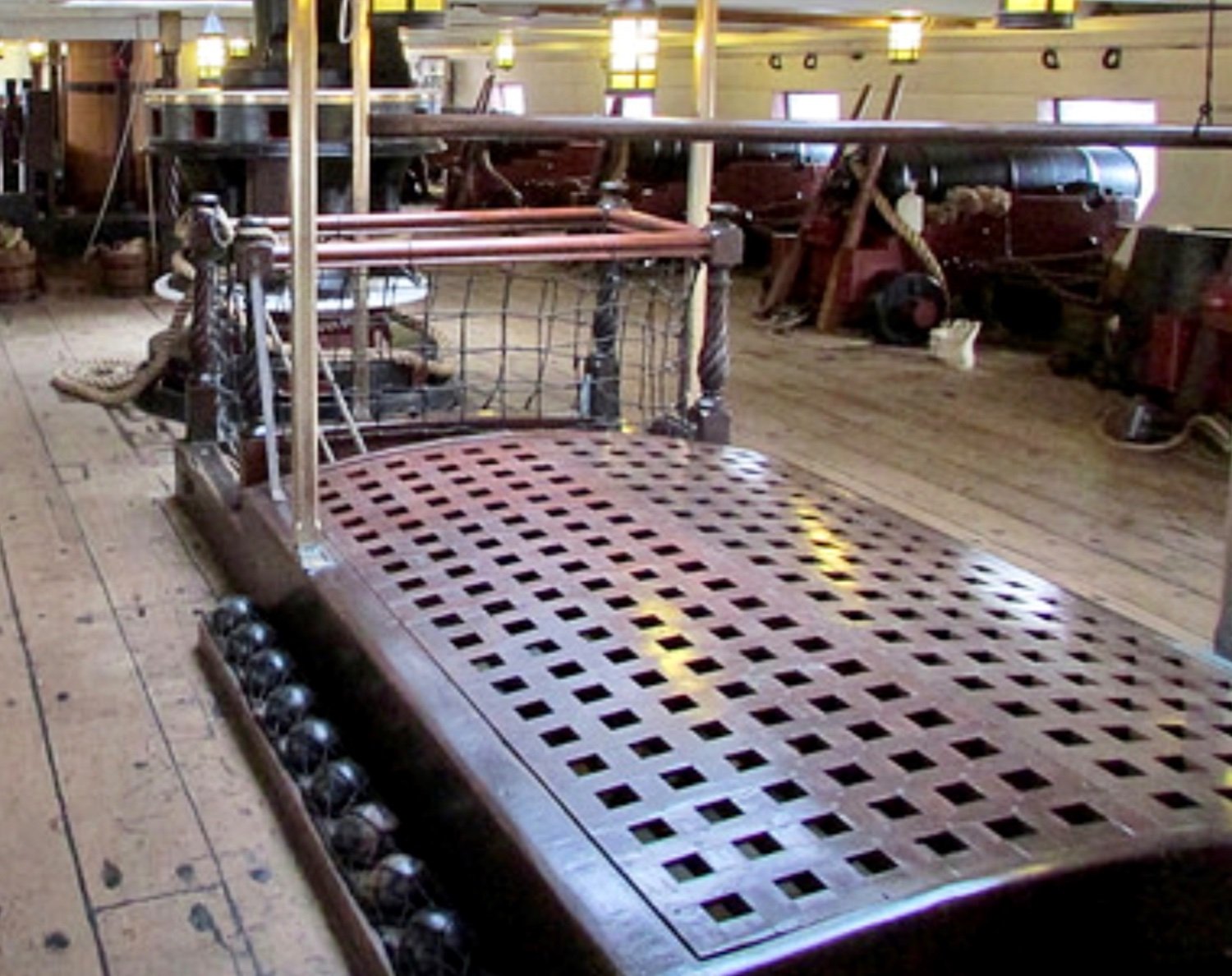
I think it’s the anti idiot device, at least if you have to pick 4 shot up you’ll do some proper damage to your toes and may just get educated in the process 😈 The shot racks around the coamings are similarly safeguarded. -
Shot Garlands
Morgan replied to tmj's topic in Discussion for a Ship's Deck Furniture, Guns, boats and other Fittings
You have to look twice, you’ve made the same initial assumption that I did. There are in fact three swivels mounted on a rail at the break of the Poop, it was shot away at Trafalgar and subsequently reinstated. The Victory’s Marines were initially drawn up on the Poop, so it makes sense to have them close to the Marines. Nelson wouldn’t have Marines in the tops due to risk of fire to sails. Gary -
Shot Garlands
Morgan replied to tmj's topic in Discussion for a Ship's Deck Furniture, Guns, boats and other Fittings
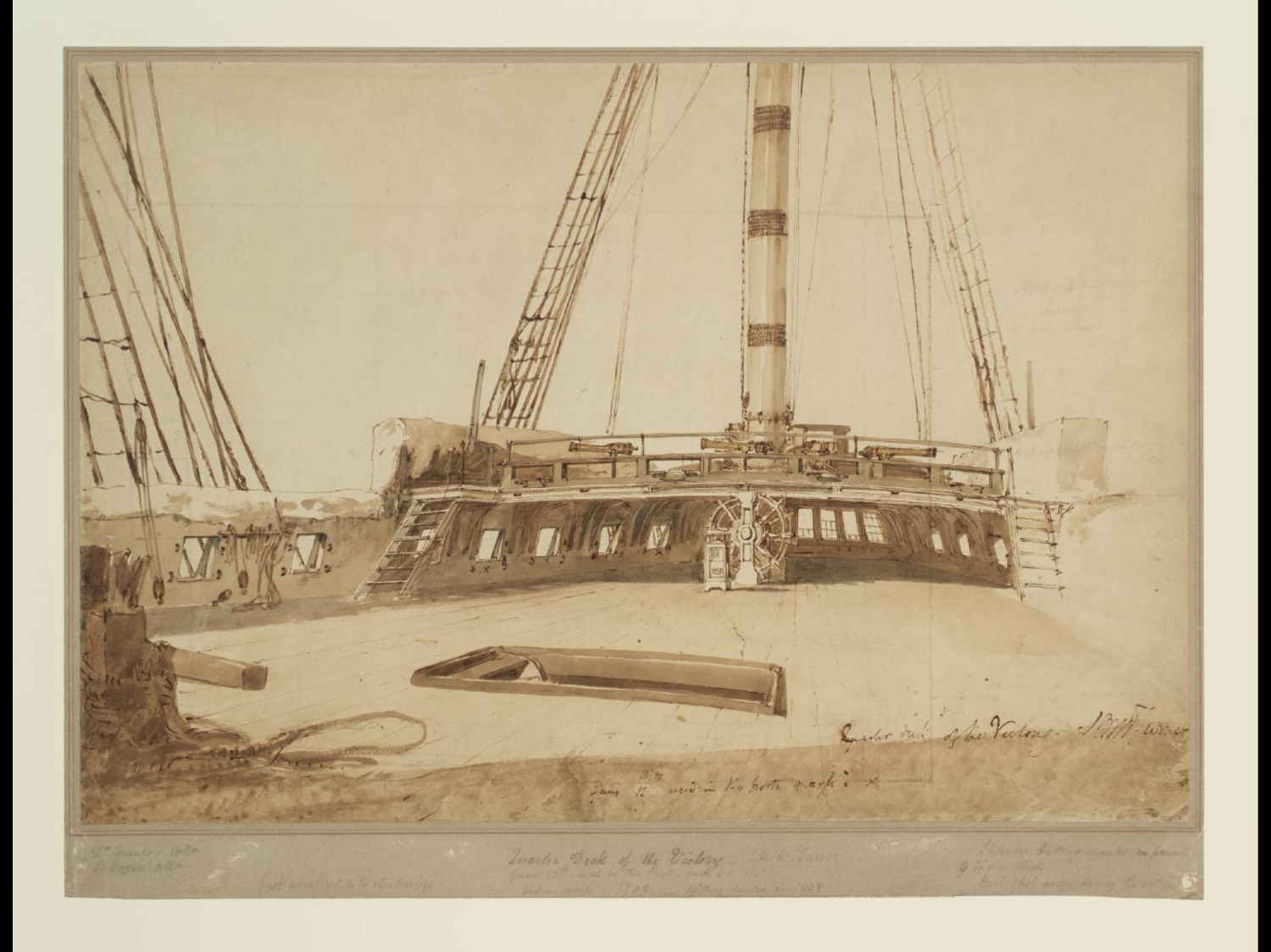
They have done that on the Victory, so I assume that they got the idea from somewhere. The photo below shows it, but it wasn’t an actual feature the ship had as per the Turner 1806 watercolour - same gunports. Gary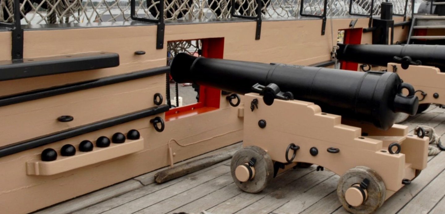

-
Shot Garlands
Morgan replied to tmj's topic in Discussion for a Ship's Deck Furniture, Guns, boats and other Fittings
For the triangular rack - 3 balls along a side, which means 6 balls on the bottom, these then support a second layer of 3, and a single ball atop. Gary -
Shot Garlands
Morgan replied to tmj's topic in Discussion for a Ship's Deck Furniture, Guns, boats and other Fittings
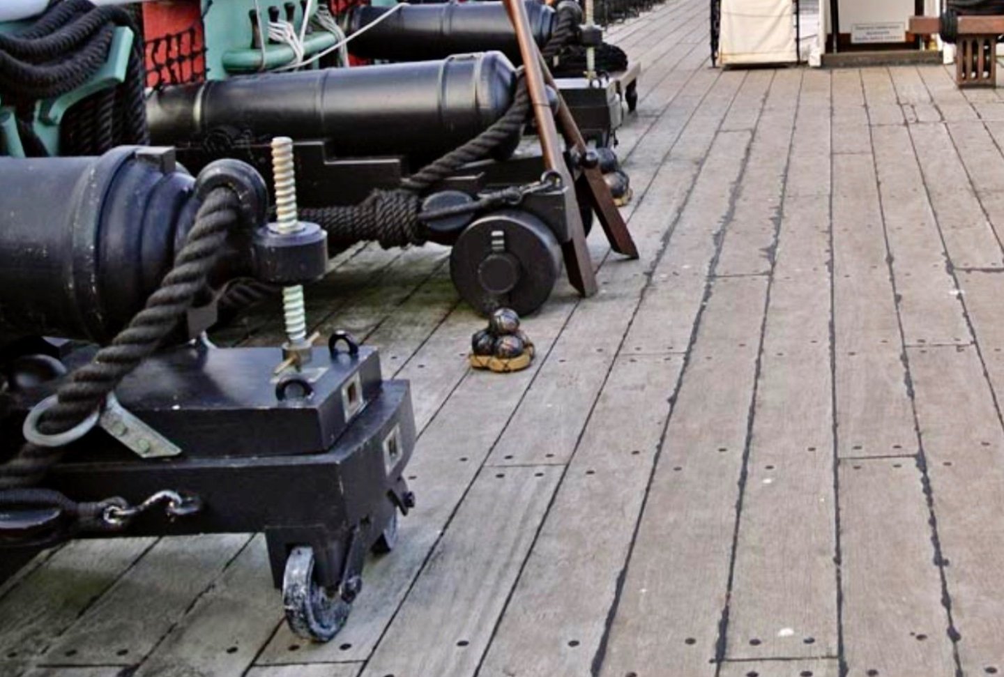
Attached are two photo’s, one shows the shot racks to the hatchway coamings, and the other is a simple rope grommet for holding 4 shot. For the triangular one’s think of a pool table rack for setting up the balls, but you would stack more on top in successive layers with the shot supporting each other to get the pyramid. Only 3 simple sides, nothing in the middle. Gary
-
Shot Garlands
Morgan replied to tmj's topic in Discussion for a Ship's Deck Furniture, Guns, boats and other Fittings
Yes they were, they went aboard in August 1804. Gary -
Shot Garlands
Morgan replied to tmj's topic in Discussion for a Ship's Deck Furniture, Guns, boats and other Fittings
Tom, From the ‘Sea Gunners Vade Mecum’: 68-Pdr - 8.0 ins. 32-Pdr - 6.0 ins. 24-Pdr - 5.2 ins. 12-Pdr - 4.4 ins. Gary -
Shot Garlands
Morgan replied to tmj's topic in Discussion for a Ship's Deck Furniture, Guns, boats and other Fittings
Tom, Waterways are the planking structures that join the side of the ship to the decks, and usually formed so as to lead any water on the decks to the scuppers. So Roger’s comments points to shot being stored on the deck along the ships sides on Great Lakes warships. However, for your Victory cross section this would not be appropriate. The British historian LG Carr Laughton, who investigated the Victory for her 1920’s refit notes that: “Before 1780 shot racks were placed against the sides of the ship. By an order of 27 May 1780 they were directed to be moved to amidships or round the hatchways if desired, and these continued to be their positions till long after 1800’s. On 29 Mar. 1803, when the Victory was completing her repair, the Navy Board wrote to the Admiralty: "Understanding that it is now the practice on board H.M. Ships to keep the shot in the match tubs and put them in grummets [shot racks / garlands] upon the deck; if this circumstance is known to their Lord- ships we are desirous of being informed whether we shall continue to fit shot racks round the coamings of the hatchways, as it appears to us to be an unnecessary work and employing men improperly if they are to be removed by the officers." The Admiralty answered two days later that shot racks were to be fitted in the usual way except upon the quarter deck. The Victory therefore must have had shot racks round the hatchways on all decks except the quarter deck“. This is reinforced by visual evidence from JMW Turner in December 1806 sketches and watercolours that show no shot or facilities to store shot are present along the ships side or around the quarterdeck hatchways. Unfortunately this was ignored and shot racks and other fanciful fittings are presently adorning Victory’s inner hull that simply weren’t in place way back when. Gary -
Shot Garlands
Morgan replied to tmj's topic in Discussion for a Ship's Deck Furniture, Guns, boats and other Fittings
I think it was just the way these were made, they were a temporary storage device used when going in to action and shot was brought up in bulk. For instance, Victory at Trafalgar had a thousand shot per deck brought up the day before battle, far more than the fixed garlands could accommodate, so these were used. The shot within them were stacked pyramidal fashion. They could be square, oblong or triangular. Gary -
Shot Garlands
Morgan replied to tmj's topic in Discussion for a Ship's Deck Furniture, Guns, boats and other Fittings
Definitely bowl shaped sockets, below is a free standing version recovered from the wreck of HMS St. George which sank I think in 1811, you can see the slight scalloping. Gary
- 41 replies
-
- 11
-

-

-
Interesting, no camber anywhere. The release video shows the parts are laser cut, so why not put that extra detail in? All for a regular price of USD $1,700 / €1,400. The price and detail run contrary to where the leading manufacturers are. It seems a matter of style over substance. Maybe we are missing the point and the target market isn’t the discerning modeller. Gary
-
It is a mish-mash of styles for sure, and clunky! Certainly not sure about Oak as the ribs and frame, not easy to work or detail at that size so won’t lend itself to modification. Also, that lattice frame approach to all the decks could easily have been substituted for a proper set of deck frames as they are all laser cut. A lot of authenticity lost for more than over simplifying the design. Also at 1:87 that is a really odd scale, OcCre don’t seem to have settled on a uniform scale. Gary
-
Hi, There is no button, you simply start typing in the box below the most recent post, in the attached picture you can see below your post is my Icon and to the right the box that says ‘Reply to this topic ….’ Simply click in this box and start typing. When done hit the ‘Submit Reply’ button to the bottom right. Gary

- 1 reply
-
- 1
-
-
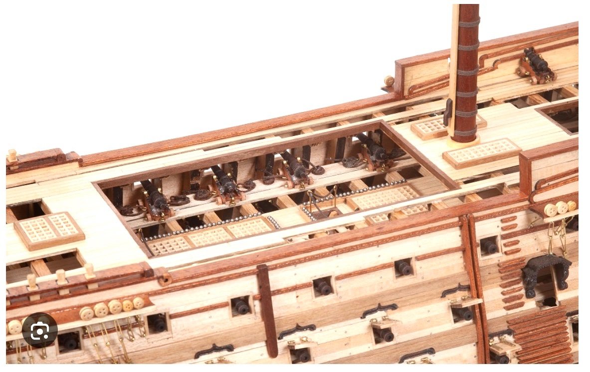
Just watched the release video feed live, very much a high level production. Not much in terms of constructional photos of the guts of the model, but looks to have each deck rigged with cannon, but nothing to see as yet beyond that. It seems like a nice attempt to produce something in the Admiralty style, but rigged! I’m torn as to my views of it, I like the concept but for the time and money they have invested it falls short on accuracy, for example in producing the frames why not get the scantlings to scale and properly detailed if the details are laser etched. It also has elements that are of a standard in keeping with a decorative model. More details still required, so the jury remains out on this one for me. Gary
-
I see the Micro-Mark photos were indeed at some earlier stage, the Model Expo site shows the finished model, with Poop, Boats, and a full set of yards and sails. Gary
-
There are a number of images still out there (erroneous courtesy of Micro-Mark), she is the usual OcCre wood pallet, but the model seems naive in part, and accuracy seems to be of passing concern. It could be these are not of the completed model, we’ll have to wait and see, but the missing Poop deck is significant. The open framing is interesting, although again seems underdone for a supposed price of circa US$1,700! It seems the Middle Deck, as well as the Upper and Weather decks (or at least those included so far) is somewhat detailed. Detail for the Lower Deck isn’t discernible, but there is a nascent Orlop. I’m tending toward these being interim construction photos, those yardless masts hint at that. We’ll have to wait and see. Gary
-
It’s still out there on Google, but as you say the link doesn’t work. Admiralty style from the look of it, fashioned from Oak - not your typical model building wood! Gary
-
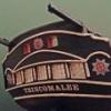
21 October - Trafalgar Day, and who was launched in 1765 - Victory! Gary
-
There are usually 3 main issues causing discolouration. Firstly dirt, second paintings being varnished, and the oil paints themselves changing, but most of this happens in the first year after painting. But having stood within just a few feet of this large painting last year it is in very good condition and clean, no sign of any discolouration from varnish - which most conservators remove these days anyway. To what extent the paint itself may have changed is hard to tell. Gary
-
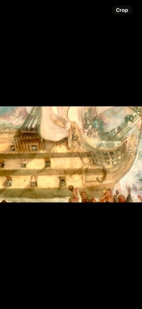
The only artist who both visited Victory after Trafalgar and produced paintings of the ship was JMW Turner. In his paintings he shows a light yellow ochre and a greyish black. This is in keeping with Flyer’s post above on scale and is what I believe you would get were you to tone down her present colour scene. Attached below is a screenshot of Turner’s Battle of Trafalgar. Gary