

Seventynet
-
Posts
730 -
Joined
-
Last visited
Reputation Activity
-

 Seventynet reacted to Bahf in Sloop Speedwell 1752 by Bahf - Syren Ship Model Company - 1:32 scale - POF Sloop
After some delays due to Easter I collected my Speedwell kit yesterday and was able to get started today.
New to the forum, I noted that Chuck would like to see buildlogs and figured why not, I can use all the help I can get. This is definitely a deep end type project for me and I expect that I will be building quite slowly. Happily I seem to have gotten a generous amount of spare parts.
Started with the stem, not sure if I did something wrong but I ended up with a bit of a ledge along the curved inboard surface. Attempted to remove the ledge by sanding along the joint marked in red, which seems to have worked out ok.
This is where I'm at with a loose dry-fit, will sleep on it and try to refine the joint a bit more before glueing.
-
Seventynet reacted to JeffT in Sloop Speedwell 1752 by JeffT - Syren Ship Model Company - 1:32 scale - POF Sloop
All keel sections are complete. Moving on to the rabbet. I think I'm not going to try an remove all the laser burn. I just gave it a light sanding to smooth things out nicely. I think most of this will not be visible in the end. Hard to get all of it on a picture as its quite long.
-
Seventynet reacted to JeffT in Sloop Speedwell 1752 by JeffT - Syren Ship Model Company - 1:32 scale - POF Sloop
Starting with the stem. I just did a quick dry fit and everything fits together almost perfectly. I haven't touched anything yet and just very minor adjustments needed. Doesn't get any better than this. I won't remove any laser char from the surfaces until they are glued together. Don't want to risk rounding over any edges.
-
Seventynet reacted to CaptMorgan in Sloop Speedwell 1752 by Capt Morgan (Steve) - Syren Ship Model Company - 1:32 Scale - POF Sloop
I've been making a little progress and got the keel finished up. Thought I would throw a few pictures of where we stand so far...
I have the build board all set to go. I pretty much followed Mikes lead - can't go wrong doing that....
Next up will be attaching the false keel - seems I forgot that till I seen the pictures... After that I think I will put on some WOP that to protect what I have done so far.
Then fixing the plans to the build board.
So far --- so good... Thanks for looking in.
Steve
-
Seventynet reacted to Rustyj in Sloop Speedwell 1752 by Rustyj - Syren Ship Model Company - 1:32 Scale - POF Sloop
I got the extra printed plans back and have completed the build board. I got a 3/4" (19mm) thick MDF board for the base. I also put two 1"x2" boards length wise underneath to ensure the board does not go out of shape. It also elevates the base in case I want to use clamps for some insane reason. The plans were attached using a 3M spray mount adhesive. It worked really well.
I also put together the keel support jigs. On to the stem next.
-
Seventynet reacted to Jim Rogers in Sloop Speedwell 1752 by Jim Rogers - Syren Ship Model Company - 1:32 scale - POF Sloop
Started assembling frames next. Some of the lasered identifiers are hard to read for me. Took them off the trees one at a time. Make SURE you check identifiers and orientation prior to assembly. Check the PLANS, make sure the ARROW in the jig faces forward. I assembled five frames and dry mounted them on the keel. Some are REALLY tight and I was afraid of issues so I sanded the char off. Fit nice after that. The jig is ingenious.
-
Seventynet reacted to Jim Rogers in Sloop Speedwell 1752 by Jim Rogers - Syren Ship Model Company - 1:32 scale - POF Sloop
I started on the Stem assembly next. Everything fit well. Took a LOT of sanding and tapering to get Mercury in proper position.
-
 Seventynet reacted to Chuck in Sloop Speedwell 1752 by Chuck - Ketch Rigged Sloop - POF - prototype build
What a difference some paint makes. Bulwarks are painted however as usual, I will be applying many more thin coats over the next few weeks as I progress.
Before and after...
-
Seventynet reacted to tlevine in NRG Rigging Project by tlevine
Most kits come with deadeyes and partially completed chains. Usually, the upper link (the link that goes around the deadeye) is pre-formed, with the bottom cut for insertion of the deadeye. Wire is provided for the builder to form the other two links but the entire assembly has very little strength and the cut ends of wire are ugly. The only way to make this assembly stronger and better looking is to solder the links closed. I prefer silver soldering, even though regular soldering will give sufficient strength. The benefit of silver soldering is that the metal is fused together rather than connected by a dissimilar metal, tin. This makes it easier to bend the part without worrying about the solder joint breaking. The downside is that there is a learning curve and the tools are more expensive. Silver solder also blackens well. There are also low melting point silver bearing solders (Tix) which can be blackened.
The measurements for all the parts of a British warship were determined by the Admiralty. There are reference books that contain this information such as Steel’s Tables. An easily read version of the tables is sold in the NRG store. The main mast diameter is given on the plans as 18”. Using the information from the tables, I determined that the main stay is 9” and the shrouds are 5.5”. Lines are measured by their circumference. The diameter of the deadeye is 1.5 times the size of the shroud or stay it is attached to, in this case 8 ¼”. A spreadsheet comes in handy in determining all the measurements.
Let me start by saying that my metal work has a bit to be desired. The chains are made from 1 ¼” wire, which is 22 gauge. I temper the wire by drawing it through a gas flame until it glows red. This makes the wire more malleable and removes any factory applied coating.
The deadeye chain is the same length for all the deadeyes. Make one and use it as a template for the others. I wrapped wire around the deadeye, leaving long tails, and inserted this into the slot in the channel. The tails were cut long enough to be able form the loop below the channel. I removed the deadeye and applied a finish.
The lower links are all the same length. From the plans I knew that the toe of the lower link is bolted 5” below the top of the wale and that its overall length was 9”. Two T-pins were inserted into the soldering board and the wire was wrapped around them, with the cut ends on the side. The middle link is different for every shroud because each is at a different angle to the mast as seen in the two pictures below. The link becomes longer with greater angulation of the shroud. You can see the difference in the shroud angles and how this would affect the length of the middle link.
To determine the angle of the chains, I put masking tape on the hull above and below the channel. A loop of rope was placed over the mast head and inserted through a slot in the channel. The angles made by the shroud were transferred to the tape. I dimpled the wale where the toe of the lower link and the lower preventer chain bolts will be located and removed the tape.
A hole was drilled through the wale where the toe of the lower link would later be bolted. The lower link and deadeye were temporarily installed. The length of the middle chains was determined by trial and error. With the deadeye and lower link in place, I formed the middle link from rope the same thickness as the wire and transferred those lengths to wire. I formed the middle link and soldered it closed, keeping the joint on one of the long sides. Then I inserted the lower link through the middle link and soldered it.
A T-pin was pushed into the soldering board and used to form the lower link toe. The lower link is also bent at the toe, allowing it to lay flat against the wale.
Finally, the wire for the upper link was passed through the middle link and soldered. The deadeye was inserted into the loop and the wire was crimped around it to fit into the channel slot, placing the solder joint in the slot camouflaged it.
And here are the ten chains, ready for blackening. The blackening chemical did not damage the wood deadeyes.
After blackening, the chains were installed. I have a piece of wire temporarily holding the lower link to the wale.
The preventer plate prevents the bolt securing the lower link from going all the way through the toe. It was made from square bar stock that was forged to the correct shape. Mine are made from sheet brass, cut and filed to the correct shape. Just like the middle links, they varied in length. The top of the plate makes a step over the bottom of the lower link toe to cover it. To determine the distance between the bolt holes on the plate, I measured the distance between the toe bolt and the previously marked lower preventer plate bolt and added the diameter of the wire the link was made from. The sequence is shown in the drawing below. After they were finished, they were blackened and installed.
To hold the upper links in the channels, a strip of molding was placed over them. Next up, the rigging begins.
-
Seventynet reacted to James H in Full Metal Beam Engine Steam Engine (RETROL) - EngineDIY
Full Metal Beam Engine Steam Engine (RETROL)
EngineDIY
Catalogue # 33ED3487709
Available from EngineDIY for USD $299.99
A beam engine is a type of steam engine where a pivoted overhead beam is used to apply the force from a vertical piston to a vertical connecting rod. This configuration, with the engine directly driving a pump, was first used by Thomas Newcomen around 1705 to remove water from mines in Cornwall. The efficiency of the engines was improved by engineers including James Watt, who added a separate condenser; Jonathan Hornblower and Arthur Woolf, who compounded the cylinders; and William McNaught, who devised a method of compounding an existing engine. Beam engines were first used to pump water out of mines or into canals but could be used to pump water to supplement the flow for a waterwheel powering a mill. They also could be used to power steam ships.
The first steam-powered ships used variants of the rotative beam engine. These marine steam engines – known as side-lever, grasshopper, crosshead, or 'walking beam', among others – all varied from the original land-based machines by locating the beam or beams in different positions to take up less room on board ship.
The kit
This steam engine kit comes in quite an anonymous and thick gauge cardboard box with absolutely no label! The box itself is reasonably heavy too, weighing in at just under 2kg. Lifting that lid off immediately shows the colour printed instruction sheets which are sat on a sheet of foam which protects the two trays of parts underneath.
This kit contains 84 parts, inclusive of screws etc. All parts are sat in foam cutouts which provide excellent protection for the assemblies and parts. I say assemblies, because I see this as more of a semi-kit in that a number of elements are pre-built, and the idea is to assemble these to the individual parts, which are all then mounted on a metal base.
A number of the parts are in plastic sleeves. These are the ones made from stainless steel, and are for building the boiler's mounting chassis, and also the fuel/igniter tray.
Work starts on mounting a number of parts to a metal stand-off frame which will eventually mount to the main plinth. This includes the piston mount/condensation block, and the column for the cross beam. Hex keys are provided for the bolts, as well as a spanner with various sized jaws for various nuts etc.
This assembly can now be mounted to the main plinth. This is done via a series of brass stand-offs. I'll also now fit the two fly wheel mounts.
All screws are tightened up except for those holding the brackets. I decided to make sure I align the drive shaft through them before properly tightening up.
This is the cross beam, and one of the number of pre-built assemblies in this model. This is composted of cast and turned brass, plus stainless steel. You can see the piston plunger on the right of the image.
This is now fitted to the column using a small grub screw to secure. I ddi apply a little lubricating oil into the piston chamber first and then made sure the beam would move freely, pulling the piston up and down. A separate sheet of instructions gives tips on how to achieve this. If not done correctly, this is about the only area which will cause enough friction to stop the engine from running freely. I found I needed to do a little adjustment of the base of the beam. That's why you can see an adjustment hole underneath this, in the main plinth. The idea is that once the piston is raised, it will drop into the piston cylinder due to gravity.
This drive arm is now lubricated and slid into the base of the piston block, and the two bearings are interred into the outside of each of the brackets. Notice the larger end isn't yet engaged into anything and is sat on the bracket simply for the photo opportunity!
You could say this is one of the main events...the fly wheel. This beautifully machines piece of aluminium will now be fitted between the two bearings, via that drive shaft. Flats are machined onto this so the grub screws have a proper surface to fasten to.
The opposite side of the drive arm is now engaged into the drive shaft and a grub screw used to tighten up to the machined flat on the shaft.
The drive wheel can now also be secured to the drive shaft via a grub screw. A small collar is used to help space the components.
This is the beam link which will connect the beam to the flywheel drive shaft. The brass fastener has a reverse screw thread which secures into the drive arm.
This beautiful little assembly is the centrifugal regulator. The lowest bolt needs to be removed from the unit and reattached from the underside of the plinth, along with the smaller bolt you can see here. Pushing the small brass linkage downwards will force the two balanced wheels outwards. This is what will happen when pressure is pushed through the brass block that you can see midway down the assembly.
A small length of silicone tube is used to link the centrifugal regulator to the condensate box/piston chamber.
Lastly, for this section, a silicone drive belt is applied between the centrifugal regulator and the fly wheel.
The boiler sits atop a stainless housing which doubles as the heat box for the boiler. The first side is fitted, via two brass shafts which also help reinforce the assembly, as well as create mounting points for the boiler securing straps.
The box is now complete, with the scalloped side towards the top, and the square cutout as shown. The latter is to accommodate the fuel tray.
This really is a very nice piece of engineering, mostly from machined brass. I remember the boilers from the Mamod steam engines, and I can vouch that there are flimsier than this, and that had soldered joints. This is a far superior unit.
The boiler is now fitted and secured. The protruding outlet pipe is connected to the centrifugal regulator via a length of silicone tubing.
The steam engine itself is now complete.
These parts assemble to create the fuel tray. This contains a tray into which the fuel (methylated spirits, IDA etc) will be poured. The 'wick' units which create a chamber from where the fuel vapours emit, are then plugged into the tray and then the cap is fitted. This creates a shield which closes off the fuel chamber from the outside world.
The underside of the piston block has that condensation pipe. This little tray will sit underneath that whilst in operation.
Instructions
These are quite sparse in text, with quite a lot of Chinese present, but the illustrations themselves are enough to easily build this steam engine.
With the engine complete, we can now give it a test. First, the safety valve needs to be unscrewed and then water added. I do this with a syringe. First you need to open the valve at the front of the boiler, or the water will just leak from the injection point, as you add it. I found that about 60ml of water was enough for this. I also added about 10ml to 12ml of methylated spirits to the fuel tray and then lit the burner. The boiler took just a few minutes to come to pressure. The flywheel began to rotate slowly, so I gave it a gentle push and off it went!
Conclusion
Firstly, I have to say that this is a delightful little steam engine that is both easy to understand and build. This took me a little over 90 minutes to build, inclusive of taking the unedited photos. The quality of parts really is excellent, which is what you need when you are dabbling with a miniature boiler unit and the pressures within. The overall feel of the kit and the finished model is one of quality. All I would suggest is adding a little lube in areas such as the piston and gearing in the centrifugal regulator etc. When you compare the beautiful finished model here, compared with the current Mamod models which are pre-built and cost over a £100 more than this, then I consider this to be excellent value for money. It will also make a wonderful cabinet display piece too, which is exactly where mine will be heading.
My sincere thanks to EngineDIY for sending out this kit for review on Model Ship World. To buy direct, click the link in the header of this topic.
-
Seventynet reacted to Chuck in Sloop Speedwell 1752 by Chuck - Ketch Rigged Sloop - POF - prototype build
Bulwark planking has finally been completed. It really wasnt too bad. You just have to keep plugging away and while making careful cuts between those ports. All the cracks, gaps and dents were filled and sanded in preparation for painting.
The second layer of spirketting was added as well to finish off the bulwarks below the ports. The top edge was softened or even rounded off. I dont like to leave a hard edge here. I used a 1/32" strip the same shape and size as the first layer. I took the shapes from the plans because this wide 1/2" strip needs to be tapered like the first layer and shaped before you glue it on. Every model will have slight differences so it will take some time to get it right. Then the top of the sills were very carefully sanded and the cracks filled there as well. I was careful not to sand into the top of the spirketting which would ruin the nice continuous run along its top edge. You can see how bad port sills look now but the surfaces are now smooth and once painted will look really nice.
Before I paint however I needed to add the 4 fixed blocks on the inside of the bulwarks. On Winnie, I had used laser cut fixed blocks the same thickness as the planking. You would glue them to the framing before planking and then plank around them. I went a different way this time. I just planked the entire interior bulwarks and then just drilled the fixed blocks through from the outboard side. Then I sanded them clean and reamed them a bit with a round file. To finish off these simulated fixed blocks I took a very small "V" gauge chisel and made a small simulated sheave slot between the two holes. Since the bulwarks will be painted this seemed like the better way to go. You can see the two fixed blocks below at the bow on the starboard side. I used a sharpened pencil to color the sheave to simulate a more appropriate color.
I have also hi-lighted in this photo how I planked the bow inboard. I first glued a 1/4" x 3/64" strip down the inboard side below the bowsprit hole. See the red arrow. This allows me to push the planking strakes up against it which for me makes the process easier and neater. There were two more strakes to add on each side of this to plank the bow inboard. The cracks were filled and it was all sanded smooth for painting.
Here is a photo showing the aft portion of the bulwarks planked and ready for painting as well. Note the two fixed blocks here as well.
The one last thing you might notice is that I did in fact add the margin plank all along the bulwarks. This is 1/4" wide and 3/64" thick. It finishes it off neatly. You dont have to add this yet but I find it easier to paint the bulwarks when I have a nice right angle to paint down to. Hopefully I wont bugger it up and get red paint all over the margin planks. But if you find it easier to paint the bulwarks first without making a mess then fell free to do it that way.
At the bow, the margin planks on each side were cut from a 3/64" thick sheet of yellow cedar. I used the plans and planking template provided. I cut it out and used that paper template as a starting point. After seeing what I needed to adjust for a tight fit, I transferred this shape to the wood sheet and cut it out with a sharp #11 blade. If you look at the photo again you can see my first attempt which I discarded. It didnt fit as nicely as I wanted. So I made more adjustments and cut another. You would be best served to buy a few extra 3/64" thick sheets of Yellow cedar for stuff like this. Every model will be slightly different and you will want to go through this exercise as well for a good fit.
I am ready now for painting....the bulwarks will be carefully painted red over the weekend. Depending on my honey-do list.
-
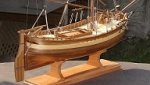
 Seventynet got a reaction from Stuntflyer in Speedwell 1752 by sfotinos - Syren Ship Model Company - 1:32 Scale - POF Sloop
I just received my package and will be starting a build log next week or so.
Ian
-
 Seventynet got a reaction from Rustyj in Speedwell 1752 by sfotinos - Syren Ship Model Company - 1:32 Scale - POF Sloop
I just received my package and will be starting a build log next week or so.
Ian
-
 Seventynet got a reaction from JeffT in Speedwell 1752 by sfotinos - Syren Ship Model Company - 1:32 Scale - POF Sloop
I just received my package and will be starting a build log next week or so.
Ian
-
 Seventynet got a reaction from Chuck in Speedwell 1752 by sfotinos - Syren Ship Model Company - 1:32 Scale - POF Sloop
I just received my package and will be starting a build log next week or so.
Ian
-
Seventynet reacted to Chuck in Sloop Speedwell 1752 by Chuck - Ketch Rigged Sloop - POF - prototype build
Just a small update...
I was eager to get started with the planking of the bulwarks. There is no trick for this. Its just a grind of cutting and shaping planks to fit between the ports. Its a slow process and you must be very neat and keep the cuts around the ports straight etc.
The planking is all 3/64" thick. Just as I did with the Winnie, the two strakes below the the ports (the spirketting) were added first. The spirketting is normally thicker than the planks above it and stands proud. I have always accomplished this by planking the spirketting in two layers. It still amazes me how few kit mfgs even show this feature. You dont have to do it this way if you dont want to. You could just use 1/16" or even 5/64" thick planking and do it one layer. Its up to you. I will add the second layer of spirketting once the entire side has been planked. I will use a .025" thick second layer.
Having said this...some notes are in order. The top of the spirketting is lined up perfectly flush with the bottom of the gun ports and sweep ports. This is great if you happened to get lucky and they all line up perfectly. I dont care who is making the model, this is pretty impossible to do. Even the most skilled builders will need to tweak the bottom sills of each port so they line up perfectly with the top edge of spirketting. This will become very apparent after you run your planking strip down the inboard bulwarks. I was very lucky in that most of the ports only needed some minor tweaking. Some were just a hair too high. Less than 1/64". So I used a sharp chisel to make the ports sits flush along the top of the spirketting. you can see that in the photo below. The ports will need a lot of paint touch up which was expected. Whatever you do, do not notch out your spirketting to accommodate a port. Try and keep the top edge of the spirketting a nice continuous run without notching it. Should one of your ports sit too low...I recommend instead that you add a sliver of wood on top of the port sill to raise it up in line with the spirketting.
I hope that makes sense.
See below...notice how I did not use any pencil to simulate the seams between each strake. In fact, just the opposite. I am painting the bulwarks red so this allowed me to take a small shortcut. You may want to consider it as well. I dont want any seams to show at all. In fact I didnt even have to use two individual strakes for the spirketting. If you look towards the fcastle bulwark planking you can see the area I havent planked yet. I used one wide strip of 3/64" thick cedar instead of using two narrower strakes as is typical. I believe it was around 1/2" wide. Probably slightly wider on the aft portion.
Then because we know the sweep ports are 3/16" high, a 3/16" strip was used next and cut between the ports and sweeps. I was careful to be very neat with these cuts.
Finally the remaining planking above the sweep ports would normally consist of two more strakes. Because I am painting the bulwarks, I once again used ONE wider strip of 3/64" thick cedar so I could quickly fill in those areas in one pass. It should paint up very nicely. This reduced the number of neatly cut ends to all those strakes between the ports. There are fewer seams to keep neat as well. The photo almost looks like a solid hull because there are few seams showing between strakes.
Now if you are NOT going to paint the bulwarks red....this means you will have to use individual narrow strakes. It will take many more cuts and trial fittings...repeat and repeat again. That is your choice. I will take more pics after the second layer of spirketting is added and after the bulwarks are painted red. The bow area will be planked with narrower strakes just as they should be. It will be easier to bend those. But once the bulwarks are painted red nobody will be able to tell how many strakes you actually used. So you must make a decision ...to paint or not to paint. Essentially you can plank what's remaining of the bulwarks with just three rows cedar strips. The wood package comes with your typical 3/16", 7/32", 1/4" and 9/32" wide planking strips that are narrow, so you will need to buy some 3/64" sheets should you want to plank your bulwarks like I have done here. Then you can cut some 1/2" wide strips instead. But only if you will be painting the bulwarks red.
-
Seventynet reacted to Chuck in Sloop Speedwell 1752 by Chuck - Ketch Rigged Sloop - POF - prototype build
It was so great to see everyone at the New London show yesterday. There were some fantastic models on display. I hope everyone has a safe trip back to their workshops.
And talking about a safe journey back to the workshop. Many of you may recall that 4 and maybe even 5 years ago, Someone swiped my mini-me off the Winnie model under construction at the show.
I am happy to report that after several years as hostage…and with no ransom paid, someone anonymously released mini-me and placed him in the depths of the speedwell model at this years show. I was happy to find him below deck upon my return to the shop. No harm was apparent on “mini-me” and he is in good health. Thank you goes out to person for having a change of heart and I am sure that both of you will sleep a bit more soundly this evening!! Since I have lost 30 pounds this year so far...mini-me will now undertake the same dietary and exercise regime that I am now unfortunately tolerating.
You cant make this stuff up!!!
-
Seventynet reacted to Egilman in Keeping my head in the game.....
And another update....
Phew that was intense....
You will probably recognize the speedo mounting post, this is the Steering Arm that slips over the right steering knuckle and bolts to the hex portion of the Speedo post....
Below is the Right Steering Knuckle with this part in place....
A very ingenious bit of design there....
Was a bear to draw though.... {chuckle} It's probably not exact, but close.... Very close....
And this belongs to the Steering group along with the Left Steering Knuckle and Center link....
And of course it mounts to the front Axel's Spindle carriers....
Glad that one is done....
And finally the overall look...
Well more detail take more time... (and I get more practice)
This one was a brain burner.... I'm sure someone more experienced in Solidworks would have done it easier, cleaner and faster... But for now, I'm calling it done...
Onwards...
Probably ready for Front Wheels and Tires....
-
Seventynet reacted to Egilman in Keeping my head in the game.....
Well another short update.... Front Axle....
Been adding the spindles carriers...
Left side...
Right side
As you can see I've started adding the details, the Grease Cups and the nuts for the steering knuckles which on the right side has the Cap Nut with the post for the Speedometer gear... (not present on race day)
Rear side...
Here you can see the round bosses for the steering knuckles which were identical left to right... Once those are designed I will then have to add a very special part, the steering arm... On the first front Axle, I designed what would be on the standard Marmon Speedster, I had no other reference... But in reality, it was a part unique to the Marmon Wasp.....
For Example....
Front, low and away and the back side.... it is bolted to the Speedometer cap nut on the front, (which locks it in place) loops around the spindle carrier the over the steering knuckle back near the steering cross link... And it's one part...
Time to experiment.... May take a while....
But I'm still making progress....
The ubiquitous overall view...
Onwards....
-
Seventynet reacted to Egilman in Keeping my head in the game.....
Well another update...
Rear Springs, I was hoping that I would be able to use the springs I had already made to build the second version... Unfortunately no That wasn't going to work so I've set about building a whole new set of Rear Springs.....
And in measuring it against the detailed photos I now have I found that I also needed to rework the Bracket as well to more accurately reflect it's true position on the car... 3/4ths inch closer to the rear and up at the turn of the curve on the frame rail...
Then I added in the old springs and the ends sat way to low, so I was forced to completely rebuild the springs reflecting the correct measured position on the car... The curve is now accurate, 40" long by 2" wide with a 3" drop at each end...
I've included two pics showing the current iteration colored in the cars natural yellow color....
And one of the spring itself showing the upper mainspring and first leaf...
and it's one solid piece as well....
Next posting when the spring itself is finished...
Onwards.....
-
Seventynet reacted to Egilman in Keeping my head in the game.....
Update;
Well starting off the rear springs, First we need the mounting plate....
The spring lays across the top and is bolted through the bottom on all four corners.... It also pivots on the shaft of the Mounting Bracket...
Here it is attached to it's bracket....
And in it position in the frame....
Next up, the upper rear spring itself.....
Onwards...
-
Seventynet reacted to Egilman in Keeping my head in the game.....
Another Update, I know it's been a while, but this part took a bit of time to re-design....
Front Springs...
And the bottoms....
All correctly laid out...
They might look a little weird when compared to normal leaf springs, this is because they are asymmetric leaf springs... Asymmetric means that one end is longer than the other...
This particular set of springs were 2" x 35" with a 15" forward axle mounting point leaving 20" behind the axle.... They have been through 8 iterations before I could finally get them to configure into a solid block and still look like the real thing...
An overall view...
They do look good if I do say so myself... {chuckle}
Anyways, I'll be taking a few days to do some RL stuff before starting on the rear springs... (shouldn't be too bad as I now know how to do them)
That's all for now, Onwards.....
-
Seventynet reacted to James H in 5 Cylinder Radial Engine (TECHING) - EngineDIY
Here is the main event! The model is actually quite large and weighty, and we haven't finished yet. The ejector rods and sleeves are now to be fitted. This is done one cylinder at a time, and needs to the rocker arms to be lifted to allow the ejector rods to sit.
The base is now fitted, and a spacer mounted between the base and engine. Once fitted, the battery charger port, switch and motor cables are threaded into the base. The cables are then plugged into a control board, along with a battery pack. The circuit is then screwed into the base and a cover fitted to hide it all. The kit also includes a USB charging cable too (not shown).
COMPLETE!
And here is a video I made of my review build.
The instruction manual is clearly illustrated and the average builder should find zero difficulty in following each stage.
Conclusion
I didn't know what to expect before seeing this kit in the flesh, and I was very pleasantly surprised. I'd had a hankering for building something like this for a while, but I suspect the mixed reviews I'd seen were from cheap copies. This kit very much surpasses my expectations in presentation, quality, and also the final result. This model took me about 5hrs to complete, but that's also because I was setting up photos of each stage. I think it's fair to say that the manufacturer expectation of about 3hrs is reasonably accurate. The instructions are very easy to follow and should present no problems, even to a beginner who has no sort of modelling or engineering experience. All parts fit perfectly together with no issue. The only things I would criticise are the hex keys which are a little soft and round off easily, making tightening the screws hard. Also, there is no lube in this kit any longer, so you will need to source your own. In all, a fantastic kit.
My sincere thanks to EngineDIY for sending out this kit for review on Model Ship World. Whilst not marine-related, I'm more than sure you'd really enjoy this one. To buy direct, click the link in the header of this topic.
-
Seventynet reacted to James H in 5 Cylinder Radial Engine (TECHING) - EngineDIY
If you see any black flecks as are visible here, these are just some debris from the foam trays. Parts with this are just blown clear before assembly. Here are the cam and gear which are simply fastened with four small screws.
The cam drive gears are now selected and assembled as shown. You'll notice the mounting pins are machined to accept the gears. The gears must also be fitted in the orientation shown in the manual.
Yes, you see that correctly....a metallic red prop! Whilst I understand that it's better to include a machined metal prop as there won't be any balance issues, I might well have selected a different colour to anodise it. Still, this is a display model and it does looks strangely attractive when fitted. Here you see the prop and the front crankcase with the bearing, collar and prop hub parts.
Now it's onto the rocker arm assemblies. It's here you'll find the only plastic parts of the engine, seen here in black. The quality is still excellent and these parts aren't at all fragile.
We turn our attention to the five cylinder head assemblies. Lots of screws to use here and you can see the exhaust ports and valves here. The valves do actually work too.
The rocker arms are now fitted to the top of the valve assemblies, and little reproduction spark plugs added. You could choose to paint the insulators in white, but I opted to leave in natural metal.
The cylinder blocks themselves are now fitted to the completed cylinder heads.
-
Seventynet reacted to James H in 5 Cylinder Radial Engine (TECHING) - EngineDIY
1:6 Five Cylinder Radial Engine (TECHING)
EngineDIY
Catalogue # 33ED3355414
Available from EngineDIY for $469.99
C. M. Manly constructed a water-cooled five-cylinder radial engine in 1901, a conversion of one of Stephen Balzer's rotary engines, for Langley's Aerodrome aircraft. Manly's engine produced 52 hp (39 kW) at 950 rpm. Most radial engines are air-cooled, but one of the most successful of the early radial engines (and the earliest "stationary" design produced for World War I combat aircraft) was the Salmson 9Z series of nine-cylinder water-cooled radial engines that were produced in large numbers. Georges Canton and Pierre Unné patented the original engine design in 1909, offering it to the Salmson company; the engine was often known as the Canton-Unné.
The radial engine is a reciprocating type internal combustion engine configuration in which the cylinders"radiate" outward from a central crankcase like the spokes of a wheel. The pistons are connected to the crankshaft with a master-and-articulating-rod assembly. One piston, the uppermost one in the animation, has a master rod with a direct attachment to the crankshaft. The remaining pistons pin their connecting rods' attachments to rings around the edge of the master rod. Extra "rows" of radial cylinders can be added in order to increase the capacity of the engine without adding to its diameter.
The kit
A 1:6 engine comes in quite a large box, as I soon realised. Actually, it's a very high quality tin, with a lid that lifts right off to display an instruction manual sitting between two pieces of protective foam. The lid itself shows an illustration of the completed engine, while the side has the kit-specific details. For an idea of scale, I've sat my Swann Morton retractable scalpel on the kit. There's a reasonable amount of weight in this kit too...approximately between 1.5 and 2kg. No surprise as this kit is 99% metal. The side panel of the tin gives a few more details.
All of the parts in this kit are recessed within sturdy foam trays that also have the part numbers engraved into the foam, adjacent to each part. This makes it ridiculously easy to find exactly what you need in each stage. There are FOUR trays of components in this kit. While there are are a number of electronics parts, with the exception of these and the plastic cylinder head rockers, everything is in cast or machined aluminium etc.
You'll notice the white plastic box in that tray. That's choc-full of screws, turned parts, springs, bearings etc. Each little section is padded with some foam. Again, there's no lube in this box. It must be something they had to leave out for some reason. Quite add as the kit contains another contentious item....a lithium battery.