michael mott
-
Posts
5,200 -
Joined
-
Last visited
Content Type
Profiles
Forums
Gallery
Events
Everything posted by michael mott
-
 Each one of these small boats is a gem, and enjoyable to watch then evolve. Michael
 -
Hi Russ Great work on the decals, The spreader is a type I have seen during my perusal of masts and rigging during my own researches I wouls suspect that it is a strong design with light weight sections. Michael
-
Ed your thoughts about precision are well taken. Working at such small scales requires a level of it in my view. To come close to replicating something that is often 50 to 100 times larger we forget that small measurements expand into enormous ones. We speak of the table of offsets being accurate to 1/8th which seems practical in full size lofting. We forget that that 1/8 reduced to the scale we work at as being of little consequence in some cases, it all being relative as you say. That said I personally find great satisfaction in being able to work by the numbers in most cases. This always for me brings to mind the precision of watch and clock making, which do not function properly without it. Your work on the 6 inch dead eyes is akin to that sort of precision in my view. drilling three holes in a piece of wood that is .083 inch in diameter was no doubt challenging. I take my hat off to you now thinking about threading all those lines to set the shrouds at a future date. Michael
- 3,618 replies
-
- 15
-

-
- young america
- clipper
- (and 1 more)
-
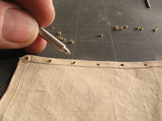
good morning Druxey, No I have not, My thinking was along the lines of the sewing glues that are used to hold seams together before sewing. The stuff I used on the full size sails smelled like copydex basically a latex liquid rubber type glue. I wanted to first see how the eyelets would work. Now I know. next is looking at different ways of accomplishing the tabling and panel seams. the sails will be sewn as well. Thanks for all the support regarding the show, and for the likes. Off to help with putting in the docks today. Michael
-
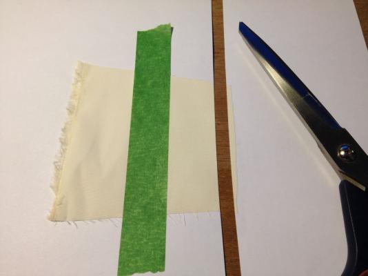
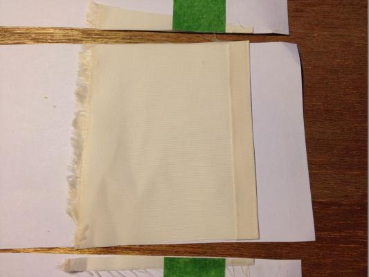
Hi Denis, the fabric in the bottom pics is a different one from the top pics I am trying to remember what the small canvas was actually made of i think it was unbleached linen or muslin. The wedding fabric is some sort of Polyester, when I am looking at the various fabrics I do a blow test through it, they must think I'm nuts at the fabric store. Thanks for the likes. Michael
-
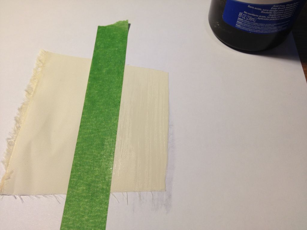
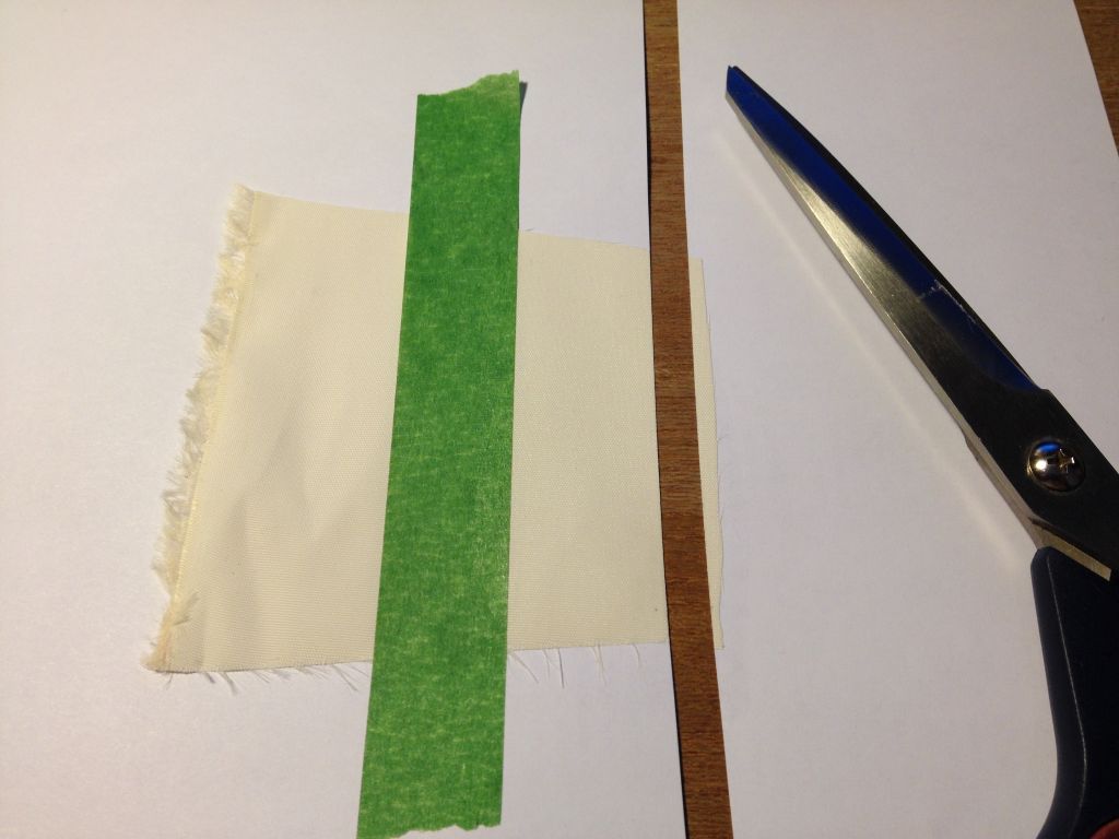
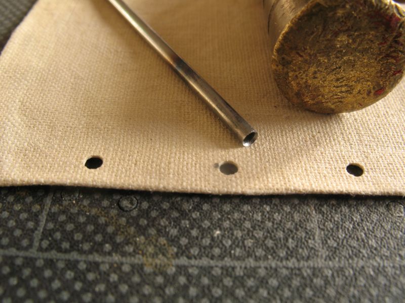
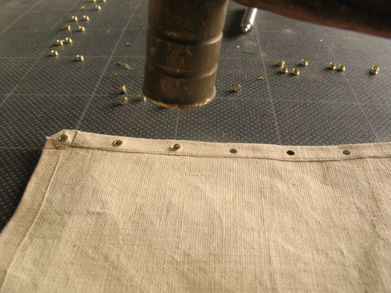
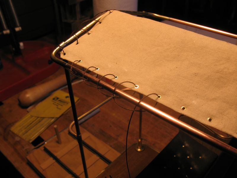
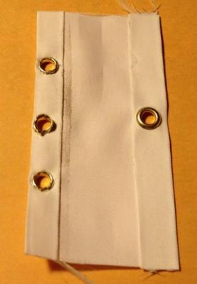
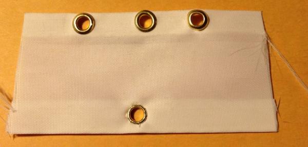
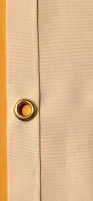
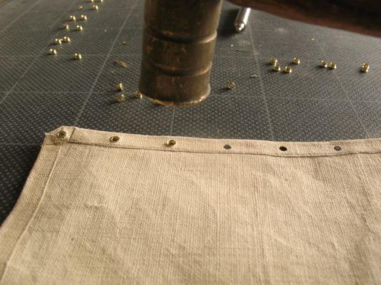
I just finished a project to get an art show open my poster.pdf On the way home dropped into the fabric store looking for the right fabric and ended up in the wedding fabrics section and found a cloth that looked good but I'm not 100% on it yet mostly I want to do some experiments on the seams and eyelets or grommets. First I used some rubber cement to glue the tabling Then trimmed the edge the rubber cement stopped the material from fraying. Then folded the tabling, I will also do one with the added tabling this will keep the cloth weave aligned. The grommets are a little large these being 3/16 diameter which scale out to 1 1/2 inch, I will locate some smaller ones I know that smaller ones are made. I might end up making the ones I need. These grommets were for a canvas cover on a 7/8ths scale model and worked well so I will have a go at making some with the backing ring, one of the issues with the tiny commercial grommets is that they do not have a backing ring. neither do the ones I made, however for the sail to function well I want to ensure that the grommets are well seated through the layers of the tabling. By making my own I can also set up any diameter that I need. the eyelets for traditional and cruising sailboats under 45 feet being size 3 or 1/2 inch diameter and for boats over 45 feet being size 4 or 5 5/8 to 3/4 diameter. these diameters are listed in the "Sailmaker's Apprentice" by Emiliano Marino ISBN 0-07-137642-9. summer's coming and I do want to get the cutter sailing before summer is over. Michael


-
Nice work on the mast Nils, good to see you back moving metal around. michael
- 2,625 replies
-
- 5
-
-
- kaiser wilhelm der grosse
- passenger steamer
- (and 1 more)
-
Wow! seeing all of them they look huge, they look almost too big. I can see why they would look cluttered on the baseboard. OK so if this were my problem which it isn't I would do the following, Make a new base large enough to cover the area that the sweeps reach I would tone down the colour of the main field of colour to a softer pale greenish grey maintaining a border of the rich colours of the existing base, on the outside of a dust cover of some sort. I believe this would better highlight the nature of this type of vessel, and display would look integrated with a clear intent. regards Michael
- 641 replies
-
- 9
-
-
- greenwich hospital
- barge
- (and 1 more)
-
I think that both of these thoughts are worth considering. I seem to recall a number of models that had spars and the like displayed alongside and carefully arranged to compliment the overall presentation, bundling them just feels a little coarse given the exquisite nature of the model. If the model is to be cased then depending on the size of the case, the display base could sit inside the cover centered in a more simple flat base inside the glass then perhaps a single set of oars as you have shown, with the rest appropriately set up alongside. If the case were not to be wide enough then perhaps a fine drawing similar to the original rendering showing the oars in situ next to the oars on blocks. Oh its mush too complex a decision. You will figure it out I'm sure. Michael
- 641 replies
-
- 5
-
-
- greenwich hospital
- barge
- (and 1 more)
-
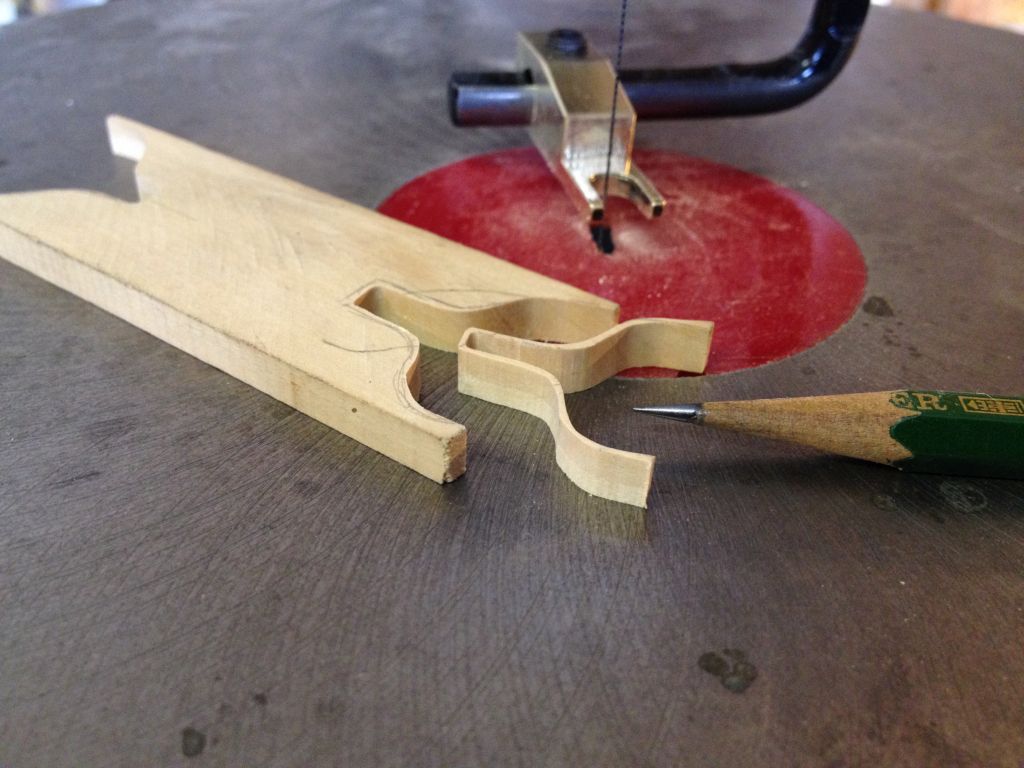
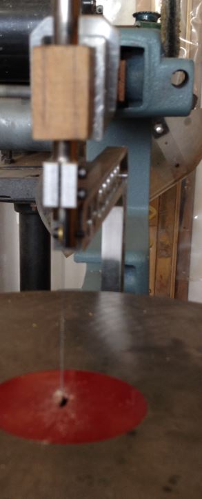
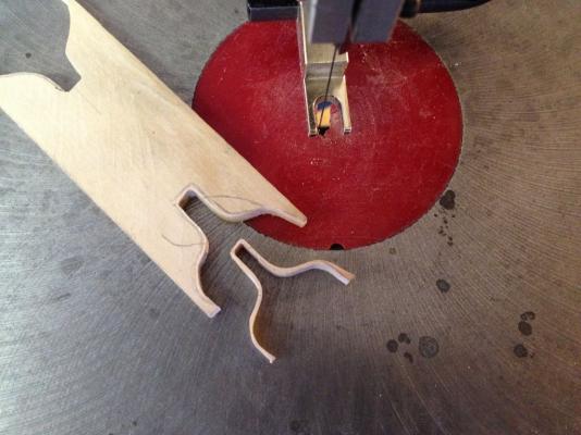
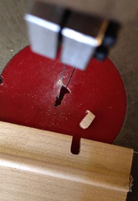
One of my issues with the foot to hold down the work from lifting was that it was just far too large and cumbersome, so I machined up a new one from Bronze and polished it I realized that i did not need it to be sprung like the original. I wanted to be able to control the area more tightly and might even make a couple of different feet I am now able to cut a close edge all I need to do now is practice using the saw. Michael

-
Hello Johann, yes thank you now I understand. Michael
-
Johan I would like to know how you cut these pieces with those snips Your work continues to amaze me is is so clean and precise. Michael
-
Just checking in Ian, what a lovely job you have done on the planking and your solution for the transom worked out very well. I also like your deck planking. Hopefully one of these days I will get some of my own projects back on the bench to get finished. Michael
-
Of course and other worthy builders too numerous to mention without hijacking the thread. Michael
-
Glen looking at the last picture brought to mind two model-makers of great renown Dr Bradbury Winter, and Donald McNarry. I do so enjoy your updates. Michael
-
Jon the same goes for us out here. Normally the ice leaves the lake around the end of April this year the ice vanished on the 9th of April just twelve days earlier on March 28th there were still trucks on the south side of the lake with folk still Ice fishing. on February 19th the ice was 28 inches thick. We will be putting the docks in on April 30 and launching Maria May 7th Very nice work on all the fittings, the models look like they are waiting very patiently for launch day. We will need lots of pictures. Michael
-
Druxey looking at these pictures is very inspirational. Michael
- 641 replies
-
- 7
-
-
- greenwich hospital
- barge
- (and 1 more)
-
Druxey, your work is such a delight to watch, exquisite work with the triple zero, the boats not too shabby either. Michael
- 641 replies
-
- 4
-
-
- greenwich hospital
- barge
- (and 1 more)
-
Good to hear that the health issues are sorted John, the model looks fantastic. Michael
- 745 replies
-
- 4
-
-
- francis pritt
- mission ship
- (and 1 more)
-
Thanks for the info Bob this scroll saw 101 was interesting The into music was a bit lame, but the chap was clear and demonstrated some great tips. Michael
-
Thank for all the feedback and likes. The saw works as well as it probably can. and is smooth. The bottom line is that I prefer to use the hand jewelers saw, I did a number of cuts this afternoon the same shape using both types of saw, and with different materials. For me the hand saw works better, and faster plus I can feel the cutting. Metal is much easier with the hand saw. So this experiment is concluded for now. I have always preferred a band saw for long curved cuts. I can put a 1/4 inch blade on the big 20 inch band saw but a smaller saw would be good . the three wheel type are good for a small bench. We all learn to use different tools and also have our preferences. This was a good learning experience and taught me quite a bit about the pluses and minuses of scroll saws. Michael
-
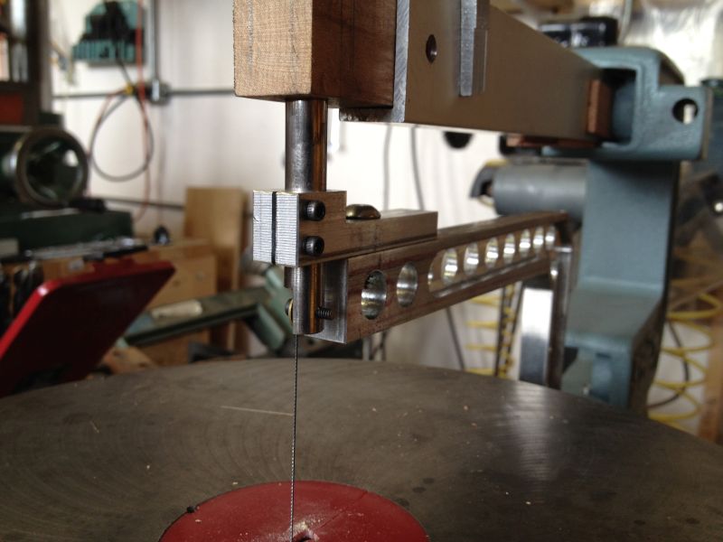
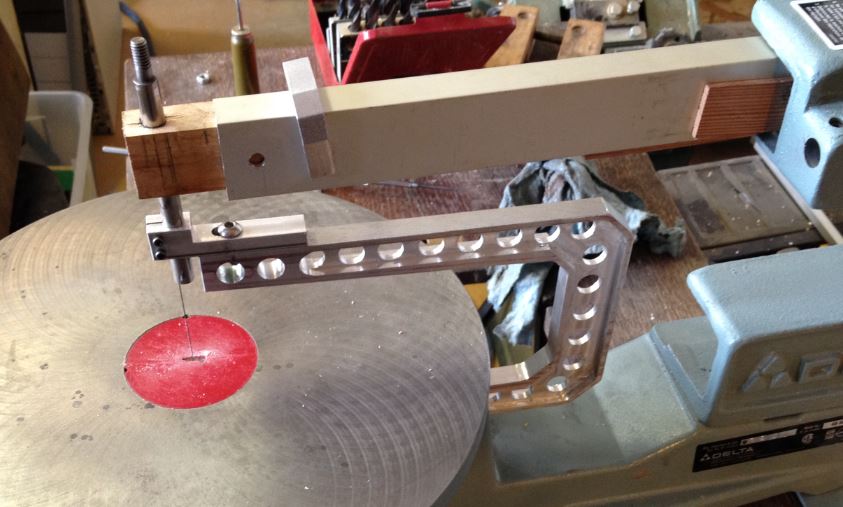
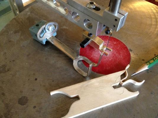
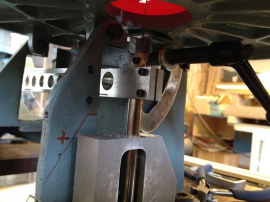
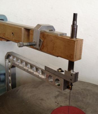
Smooth as silk I fabricated a strong lightweight arm from some 1/2inch aluminum plate I did not have anything wider than 5 1/4inches so had to make do with a slightly narrower height that the 6 that would have been optimum. I made it as light as I could, I probably could have made it a bit lighter but this arm is lighter than the original steel one and is much more rigid. it is clamped to the bottom slide bar with a couple of 4x40 cap screws. There is about 1/8th adjustment fore and aft on the top slide both for the blade and for the guide block. The cut through some 1/4 inch maple was very smooth and I felt that I had good control. Now to polish it all up and finish off the clamps for the top arm. Michael


-
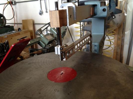
I just got back for an overnight in the city, Bob your comment about the rope versus the solid link makes so much sense, The other comment about a large coping saw is basically where i was going next with the top guide to keep the top of the saw in line without the spring. I'm off out to the shop now to sort this next part out. Michael