michael mott
-
Posts
5,200 -
Joined
-
Last visited
Content Type
Profiles
Forums
Gallery
Events
Everything posted by michael mott
-
 Thanks for all the likes and feedback. I have read that one has to fail a number of times before the final device/tool/modification/invention works well. I can attest to that comment. The geometry of our human ability to use a hand tool efficiently and skillfully belies just how difficult it is to replicate those movements to accomplish the same work in a different way. The ongoing work on the saw has given me pause to think about the actual motion of the saw blade when fixed into a mechanical device that is mechanically operated versus the action imparted by the human arm and hand. I can now understand why the manufactures have used parallel arms, it allows for a consistent tension on the blade, which the sprung loaded top spring does not, at least in the configuration where the blade is tensioned with a compression spring. If the bottom slide comes up and the top slide is unable to pull up the blade..... yes it bends and snaps I did this a few times with older blades, increasing the tension on the top spring which I tried does not work either just as many blades snapped. I have used the top blade capture device from the original saw and fitted it to some 3/8 rod with a 4x40 screw sleeved to fill the larger hole in the original arm. I have also fitted a linked arm to the bottom slide that ensures a smooth up and down that is a constant and positive motion. I am now going to fit a new U arm between the top and bottom slides keeping the top slide housed in the top arm above the new U arm this will allow for a constant tension on the blade which needs to be set so that there is a slight angle forward from the bottom to the top the combination of these two conditions will improve the action I think. Teh top slide will also keep the top part of the U arm in a more guided position with no wobble. Tomorrow we will see. Michael

-
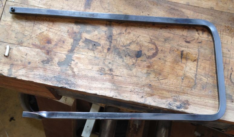
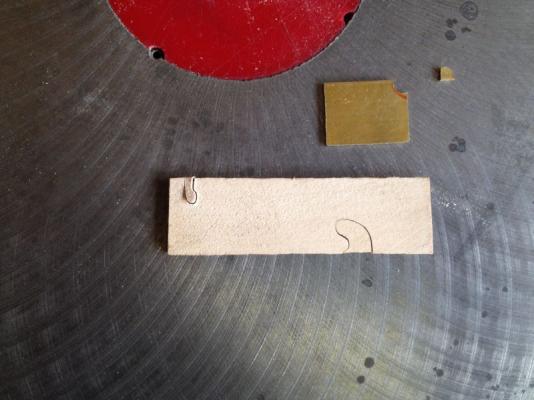
A new direction is under way. First I cut off the top part of the U arm this will be the foundation of a new deep hand held jewelers saw this left the slide bar with the clamp for the blade for the bottom of the blade this will be fixed to the foot pedal with a solid arm link to keep the bottom slide with a positive motion both up and down I put the frame part for the arms of the original saw back on the base. and will add in a piece of aluminum u channel 1 1/2 x 3/4 with 1/2th inch wall section inside this is a piece of birds eye maple that will be fixed with the ability to slide forward and backward with a micro adjustment to ensure the blade is vertical. The top of the blade will clamp to a slide inside a metal support that will be sprung loaded to pull the blade up. Michael

-
Having said that I am now rethinking a couple of things I feel that a new design evolving looking at the proxxon design, and the contents of my various scrap boxes. Michael
-
Moxis I think that for the model ship work the saw that Mark linked to would be a good bet for the price. It looks like a good tool I wonder how many of the forum members have one and what they think of it? Michael
-
Hi Bob and Mark, Yes a bit outside the box so to speak. Mark you are correct the whole U shaped piece moves up and down vertically the trick is to make sure that the blade is set vertical as well I am still working on that The use of the saw feels a lot different than a regular jewelers saw so I am unfamiliar with the fell of it , I will probably stick to the hand one for metal but I think that for some of the woodwork there is definite potential. Still a few kinks to work out but it feels quite promising. Tomorrow is another day. Oh yes and thank you all for looking in and the likes Michael
-
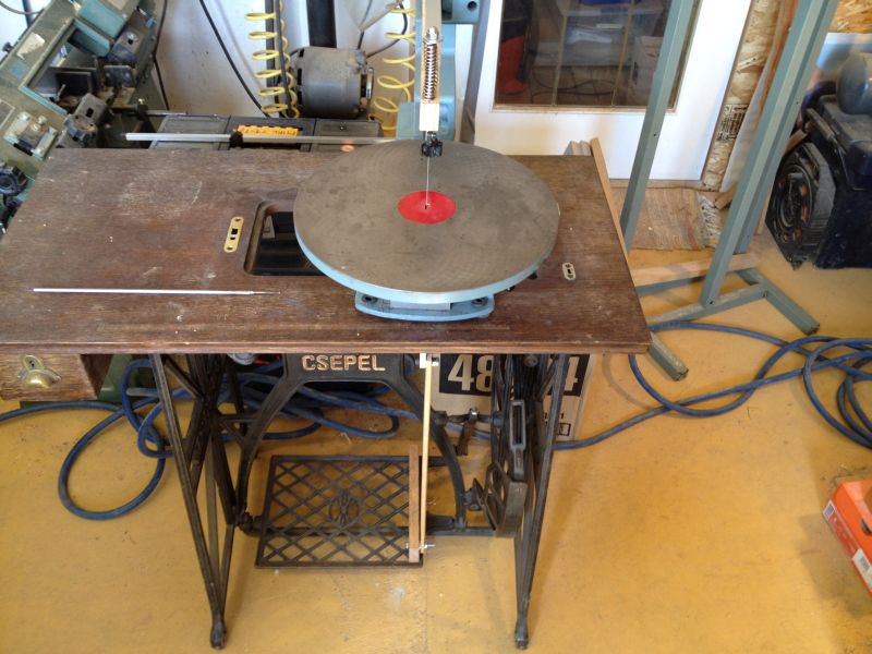
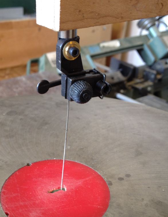
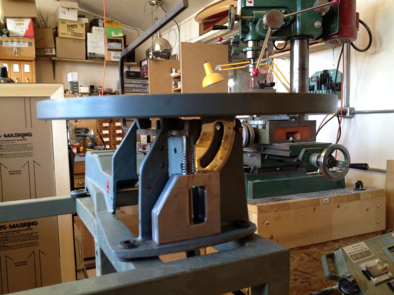
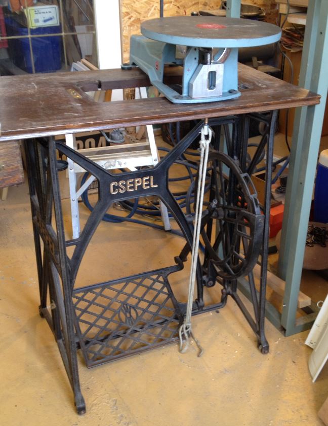
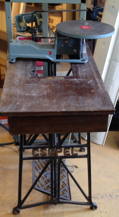
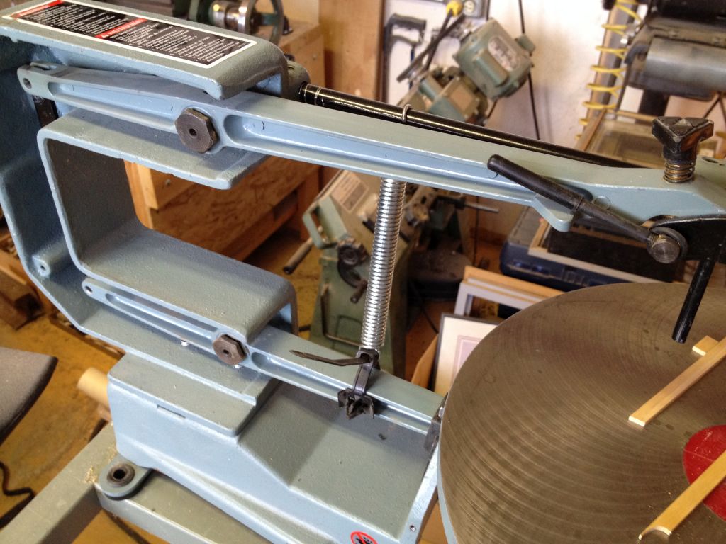
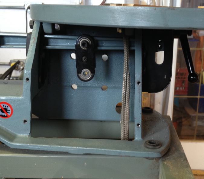
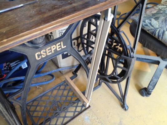
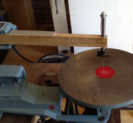
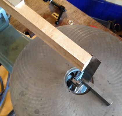
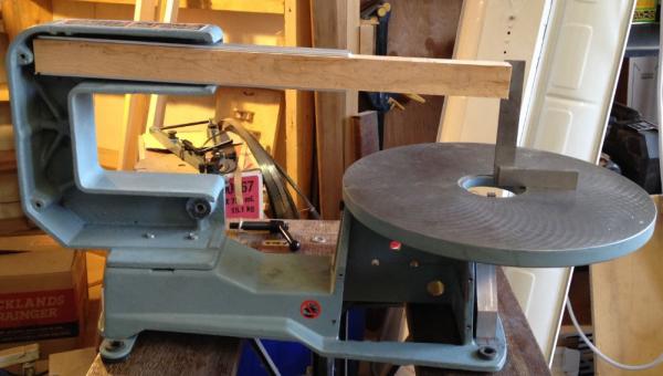
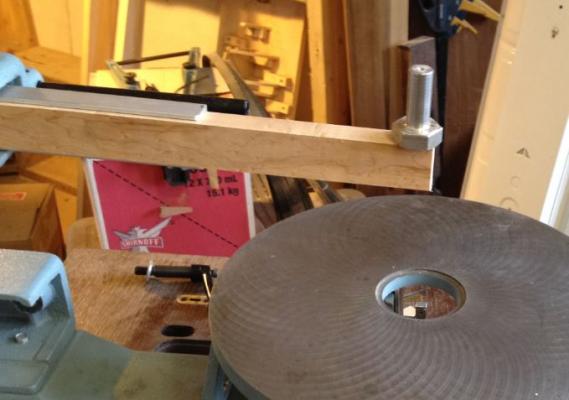
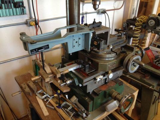
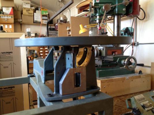
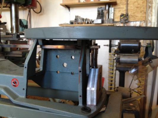
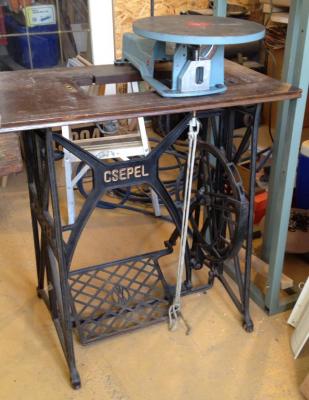
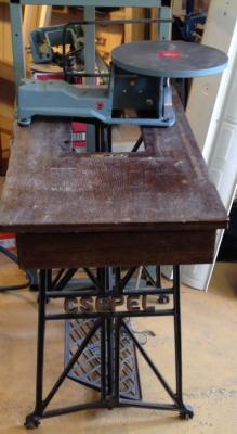
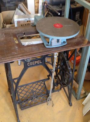
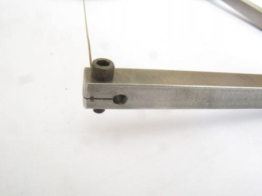
Bob the only part that I have now decided to keep is the base casting and the tilt table. I machined up a piece of 3/4 inch thick aluminum scrap I had in the scrap box to fit to the cast iron base this entailed drilling a few holes so that I could bolt it up. It took a while figuring out how to hold the odd shaped casting but it all worked well in the end. This next picture shows the new slide block attached to the casting. the rod that slide up and down is a polished 3/8 roller from and old scanner. at the top end I silver soldered a U shaped frame bent up from some 1/4 x 5/16 bar steel I heated it to cherry red with the propane torch in order to accomplish this. a side view, just to the left you can also see that the 5/16 x 1/4 bar has a 90 degree twist so that the wide dimension become vertical for the U portion of the frame. A spring from the spring scrap box was shortened to act as the return up. The grey steel frame has been set aside to be used for another purpose and the base of an old treadle sewing machine has been dragged back into service as the power source for the new powered jewelers saw. presently as a test to check out the principle the bottom hook of the slide is connected to the front of the treadle with a bit of 1/4 inch line. This arrangement seems to work quite well and there4 is a great deal of control on the speed which is much slower anyway., the flywheel effect of the sewing machine large belt drive is a bonus. From the end the overall profile, all that is left to do is add the blade holders for the top and bottom the bottom one will be threaded into the steel bar just in front of the slide, the top one will function the same way as the small jeweler saw that I made some time ago. I will place a new full top over the sewing machine one I might move the saw to the left so that I can take advantage of the treadle drive for a belt driven tool in the future. All a bit Heath Robinson but I had not used the sewing machine in twenty years, and I have others anyway. I use the jeweler's saw a lot and this will be just another version of a great saw. Michael
- 30 replies
-
- 13
-

-
Great to see an update Russ. Michael
-
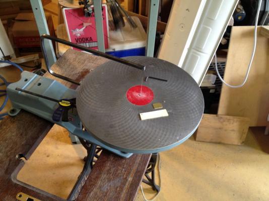
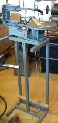
I have an old (brand new ) 2 speed 16" Delta Scroll saw model 40-560 That i purchased 20 years ago. I have used the saw as manufactured perhaps 3 times and even on the low speed thought it was rather challenging to get a smooth cutting action. so I mostly used the jewelers saw because of the much smoother control. What I am looking to accomplish is to use jewelers blades in a scroll saw in order to be able to cut both wood and metal with a little more precision than I can presently achieve by hand. My question relates to the action of the blade which seems to not move up and down in a vertical mode is this a common condition of scroll saws? I only discovered how much this moves off vertical when deciding to make this tool work without power so that I could slow it down more, and work with both hands on the work. I took off the motor and all the electrical parts and jury rigged it up on a metal frame I had kicking around, I used a rope to a foot lever to pull the saw blade down and a tension spring to pull it back up, the geometry of the arms is the issue. even with the rather disconcerting motion of the blade essentially in a back and forward motion as the blade goes up and down the ultra control with my foot pedal made cutting some very small parts manageable and far easier to control than when under power. Michael


-
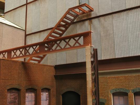
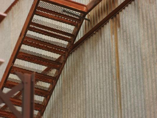
Hi Denis there is a great material for open metal treads it is an aluminum sheet for sculpting I used some for these steps Michael
-
Oh OK now I understand, it is interesting that on some of( Gil Smiths PDF) Catboats he used as few as 11 planks I think it was. Here is a great set of photos of a catboat being planked. Michael
-
I think it look like you have done a great job so far Ian, I wonder if you laid it out for 7 planks on the opposite side and looked at the difference regarding the sharpish turn at the bilge on the transom landing in the middle of the plank on the side that you have marked with 6 planks. I personally would go with 9 planks because I think it would feel better to me. Not having the model in front of me I could be just completely out of it, it is just an opinion. Regards Michael
-
Albert Adding to all the positive comments seems so inadequate, it is so inspiring to watch an artist making magic. Michael
-
Hi Johann, thank you for posting the pictures with the work in progress. When looking at the macro photographs it becomes easy to forget just how small these superb model are in their own right. When the tiny parts are part of the overall picture with your hand holding the very small drill while working on the "nails" It suddenly puts the whole thing into perspective. Your photographs are both very inspiring and humbling, and also educational at the same time. Michael
-
Hi Druxey, beautiful work, your fluting inspired me to jury rig up a fluting tool based on one I used in an architectural model in 1977 I have linked to it in jigs and tips Michael
- 641 replies
-
- 3
-
-
- greenwich hospital
- barge
- (and 1 more)
-
Oh Glenn.... I'm mortified.... simply mortified Actually I had not realized the rods were that small a diameter, and if you mentioned the diameter in the text I missed it because of the impact of the pictures. And who need to struggle with 000 x 120 anyway. Michael
-
96 U bolts, that's 192 threaded ends, a lot of threading and tapping on top of the woodwork, you were a busy man this week. Michael
-
Cutty Sark by NenadM
michael mott replied to NenadM's topic in - Build logs for subjects built 1851 - 1900
And Paul's mother said... "fear is the mind destroyer" I heard Ray Bradbury speak during a dinner under the wing of the spruce goose in 1986 at the ASTC conference. Michael- 4,152 replies
-
- 6
-
-
- cutty sark
- tehnodidakta
- (and 1 more)
-
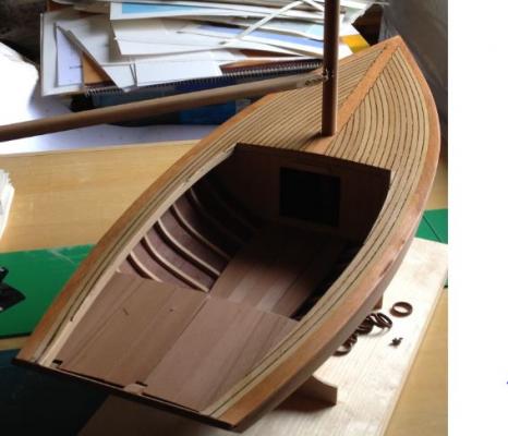
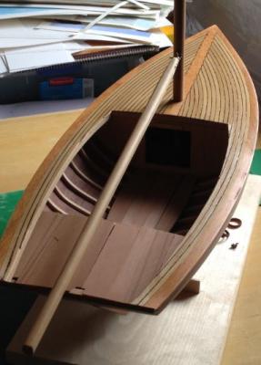
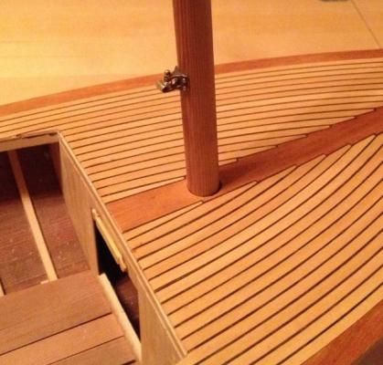
Quick update I roughed out a boom today it is clear fir I will sit on this for a day or so and see how it feels then/ Michael
-
My goodness I can't even keep my computer desk that clean and tidy. The hull framing is looking very nice. Michael
- 969 replies
-
- 3
-
-
- hahn
- oliver cromwell
- (and 1 more)
-
I'm just lost for words.......Where are those knitting needles..... I must find them. Lovely Druxey. Michael
- 641 replies
-
- 6
-
-
- greenwich hospital
- barge
- (and 1 more)
-
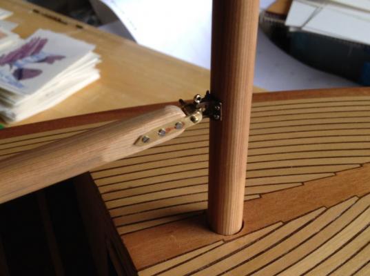
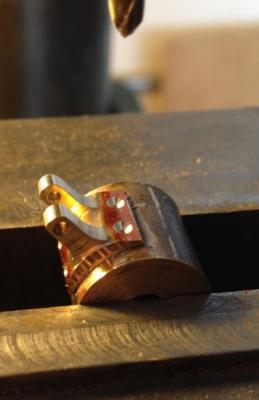
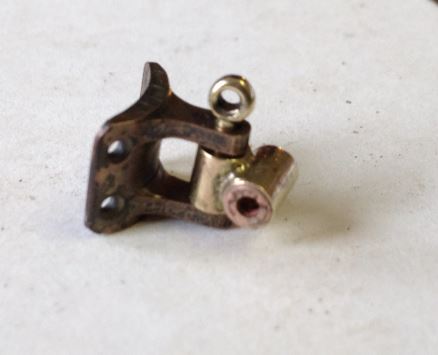
Hi Steve, Thanks for the tip regarding the soldering, I know that one need a little more heat to un-solder Initially I had thought that my large iron would be good, but I thought that the propane torch would be quicker, it was definitely a surprise that it did not just fall off. Isn't that the great thing about this hobby, we just keep learning new things all along. At least I know how to get that aged bronze look on a small piece of bronze now. On a side note I just finished reading the silver soldering article in the spring edition of the Model Ship Builder Journal it is very good. I might just invest in a smaller jeweler's torch and some of the paste type silver solder as well, I need to get some more liquid silver solder flux. because soldering the two small pieces of brass rod was a bit of a pain with the paste flux which kept falling off the small parts. and thanks to all who added likes and comments Michael
-
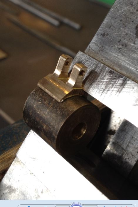
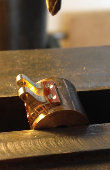
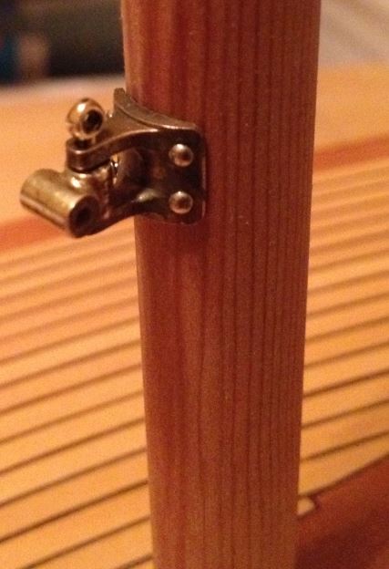
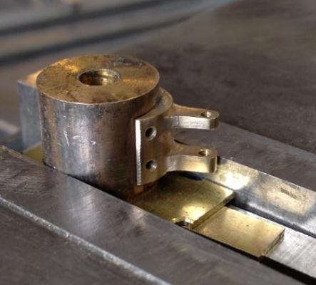
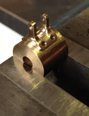
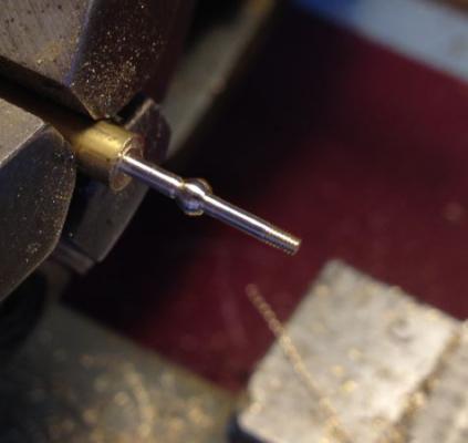
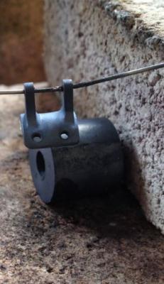
Thanks for all the positive comments and likes. Continuing on with the goose-neck the filing of the opposite side.and the ends I also needed to thin down the tongues a bit. Next the holes for mounting to the mast were drilled and countersunk. Then some final polishing, this was done with some wet and dry narrow strips and a brass wire hand brush. the piece was now ready to be unsoldered. The releasing from the bar did not work in the way I had imagined, I had expected the short piece of bar to drop off because of its weight, but this did not happen, the capillary action of the soft solder was greater that I had anticipated, and by the time the assembly had gotten quite hot I realized that I would need to assist the parting. this I did with a steel scriber. I had to work at removing the scale next, more work with the wet and dry and wire brush, the resulting look was now more like aged bronze with actually works for me. the swiveling part of the boom end was made from a couple of pieces of brass rod drilled out to be a loose fit on the pin. The goose-neck is now temporarily attached to the mast with some dressmaker's pins. Michael


-
ancre La Salamandre by tadheus - 1:24
michael mott replied to tadheus's topic in - Build logs for subjects built 1751 - 1800
Very clean work Paul. Michael