


gak1965
-
Posts
725 -
Joined
-
Last visited
Content Type
Profiles
Forums
Gallery
Events
Everything posted by gak1965
-
 Three of them will be upside down, so at least their deficiencies will be less visible. I need to see what a BlueJacket one looks like before deciding. Maybe the boats in the davits will be off doing something and not around...😀
 -
They look very nice which, much better than the casts from MSW. Looks like some more purchases from BlueJacket or scratch building some replacements. Thanks! George K
-
Rob, I've looked through the log to try to find the if you mentioned it, but haven't found it. Are the ship's boats scratch, kits from Model Shipways, castings from BlueJacket or something else? She is looking fabulous! George K
-
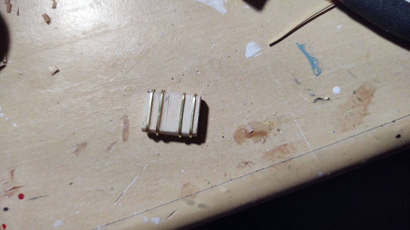
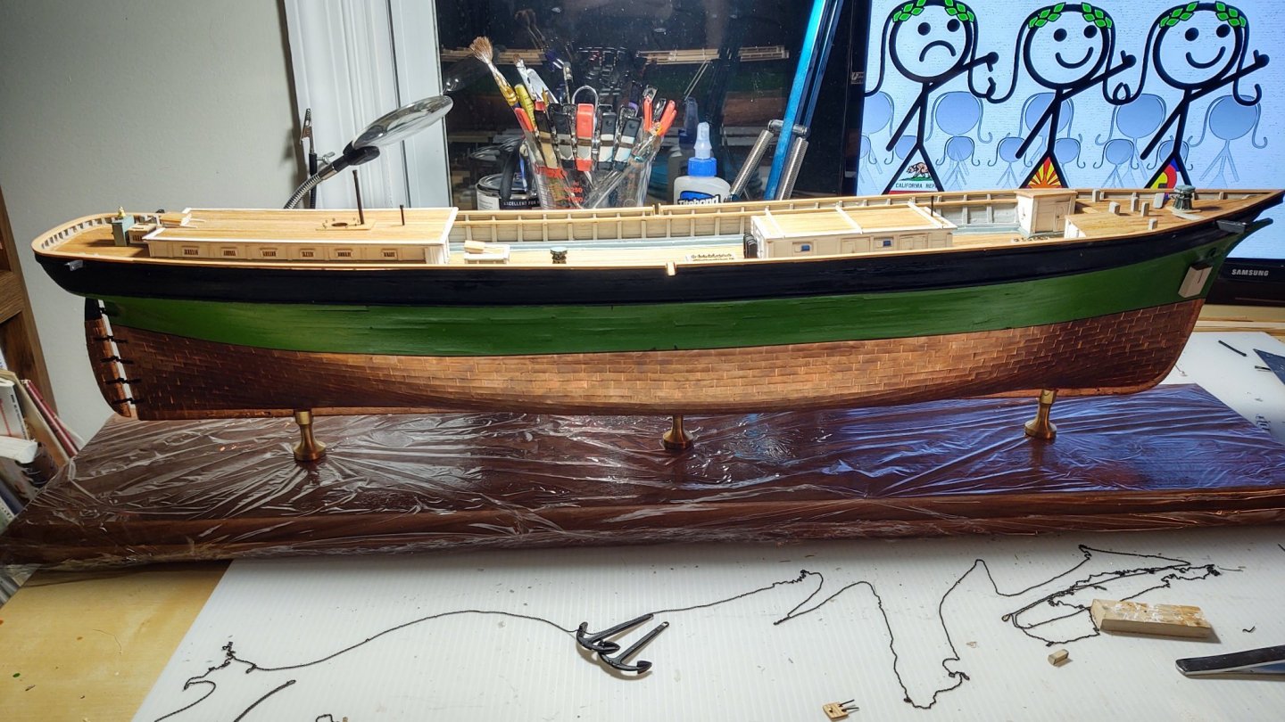
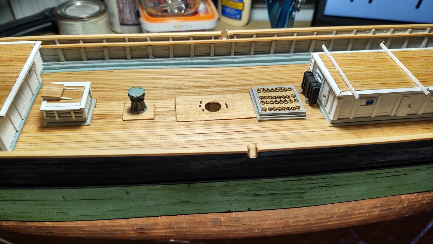
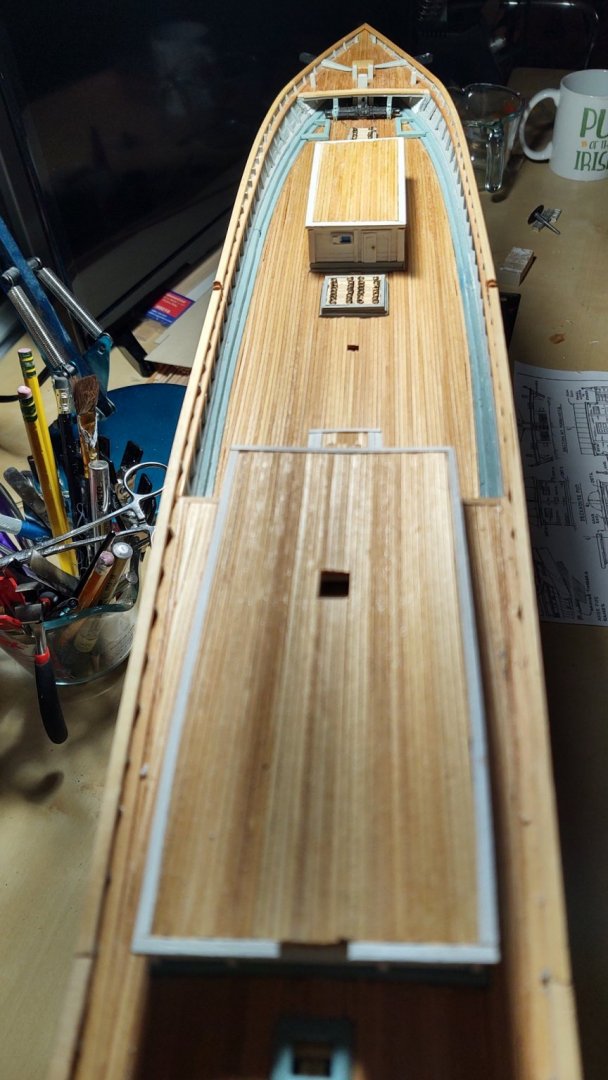
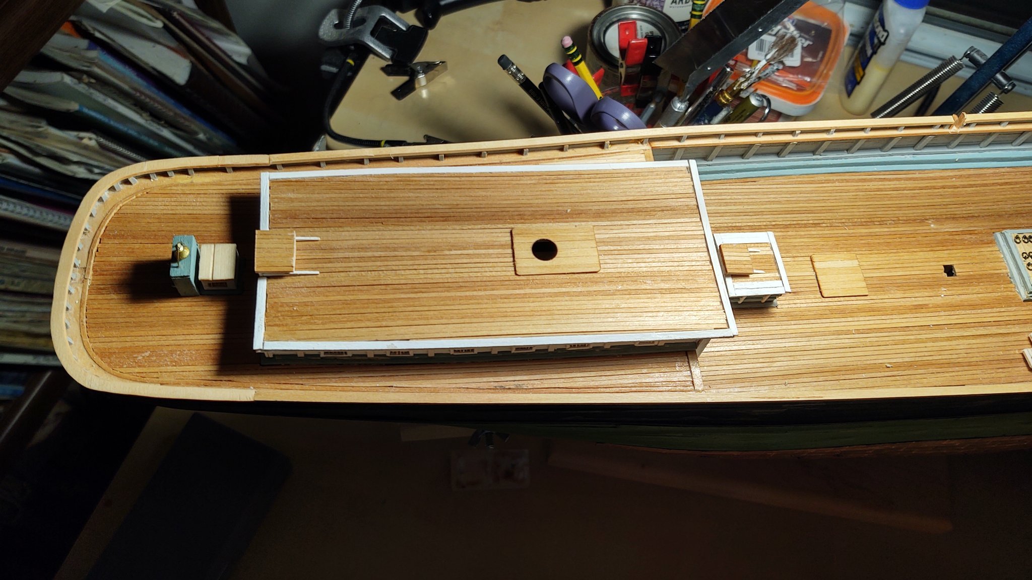
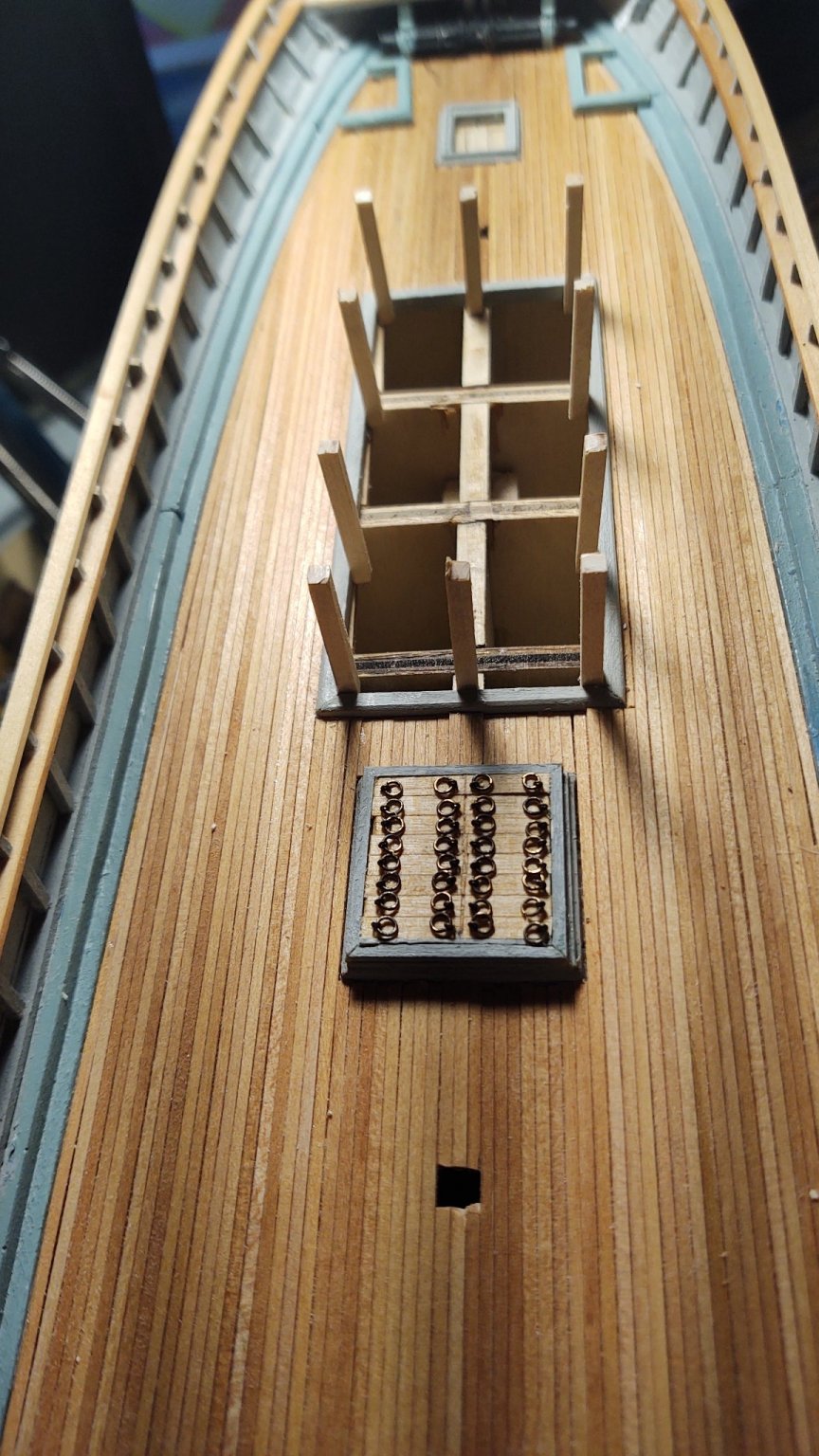
I've been doing a lot of different things but not ones that have massive impacts on how the ship looks writ large. With that said a couple of updates. First, I put the ship on its build board. A standard Dremel cutting wheel did in fact cut the brass posts nicely, although as you would expect the brass got very hot in the process. So here is the ship (with some of the other things completed) mounted. Because there is going to be a lot of paint around the ship for the foreseeable future, I wrapped the board in Saran before pushing the screws through. Once I'm done, I'll just pull it off. As I said, I've done a variety of detail work. As you can see, I discarded the water tank, and scratch built a new one. Here are a set of photos that show its construction and placement: In the next photos you will see that I've built the ladder on the cabin, put the boat supports in place, added the pads around the fore and main masts, installed the capstans, several of the vents, the boomkins, and a number of the deck mounted eyebolts. The eyebolts that are supplied are way to big, and I've replaced them with 0.75 mm eyebolts (that's about a 3 inch eyebolt at scale), but they were leftover jackstay eyebolts from the Niagara and I need to buy more. I also blackened some chain for the boomkins and some brass to make hinges. You can see the ones I put on the store hatch, and in one of the photos you can see the start of making hinges for the two hatches that mount next to the carriage house below the poop deck. I'm going to keep working on these details while planning out the cutwater and naval hoods and then carving the figurehead. As always, thanks for the likes and looking in! Regards, George K.


- 602 replies
-
- 5
-

-
- Flying Fish
- Model Shipways
- (and 2 more)
-
They were all one size, I'm afraid...
-
Happy Thanksgiving all! Just a quick update. I've been working on some smaller details. The first is the stores hatch on the stern. I put some spare stained glass material one of my kids left behind to fill the openings, and then put in the bars and the split ceiling: Next, the binnacle cabinet. When you see the last two photos which include the Britannia casting for comparison, you will see why I chose to scratch build a replacement. The first pic shows the back, sides and the framing for the place where the compass sits, the second shows the completed but unpainted version next to the casting, and the final photo shows it painted with the bell. The plans say to make it bright, but the combination of the small parts and the wood I had available argued for paint rather than leaving it bright, so I went with the color of the coamings. Finally, a couple of views of the ship, the first with only the stores hatch in place, the second showing the stores hatch, the binnacle, and the two pads I put in place, one on the carriage house that has the round hole for the mizzen mast, and the other on the main deck for one of the capstans. Thanks again for looking in, for the likes, and the encouragement! George K
.thumb.jpg.5bb30d72cdfafbe28acac368e4cfbc6c.jpg)


- 602 replies
-
- 4
-
-
- Flying Fish
- Model Shipways
- (and 2 more)
-
Glad to see you back! Quick question about the gaffs. How did you make the hinge? Is it articulated or rigid. Everything looks fantastic! George K
- 399 replies
-
- 4
-
-

-
- cutty sark
- revell
- (and 2 more)
-
Wow. Is your kit the solid hull or the POB? My understanding is that the transition happened in 1979 (ish), so right about the age of your kit...
- 602 replies
-
- 1
-
-
- Flying Fish
- Model Shipways
- (and 2 more)
-
Thanks for the complement! i probably give MSW too much grief, as I like their kits (this is my third one, after all). The wood is decent, the non-Britannia fittings are actually pretty good and the plans are excellent. I also like that they are kind of “semi-scratch”. I feel like I’ve now scratch built enough that I will be able to tackle the next project, a scratch build of RRS Discovery. i wonder if the problem here is the scale. 1:96 is just going to be harder to do well than 1:64, the scale of the other two MSW ships I’ve done. The bulk of the castings in those other kits were fine, but they were also larger and more symmetrical (gun barrels, anchors, life rings, and the windlass barrel on PoBII). Some might have benefited from simplifying, e.g. casting only the windlass barrel,and not bothering with the water tank and anchor stocks, which are easy to build. Regards, George K
- 602 replies
-
- 3
-
-
- Flying Fish
- Model Shipways
- (and 2 more)
-
Thanks! I am still hoping to sail on the real one once the pandemic abates and they start up again on Lake Erie.
- 602 replies
-
- 2
-
-
- Flying Fish
- Model Shipways
- (and 2 more)
-
Thanks! I don't have a table saw and this one is now moot, but worth checking when the Fish is done. The hardest part was that only one branch of the small hardware chain we use stocked large enough sheets to meet the needs of the case, and even then it was only on stock sporadically.
- 602 replies
-
- 1
-
-
- Flying Fish
- Model Shipways
- (and 2 more)
-
Yeah. Somehow there is this crazy expectation that real life was sepia toned in the past, when, if anything, color choices were often much more bright/garish. Athenians would be disappointed at all of those unpainted lintels on our federal buildings, Civil War soldiers went out and fought in red and blue Zouave uniforms, and through much of medieval Europe there were (generally ignored) sumptuary laws to keep the lower classes from dressing up too much. I mean, look at the Vasa for goodness sake.
-
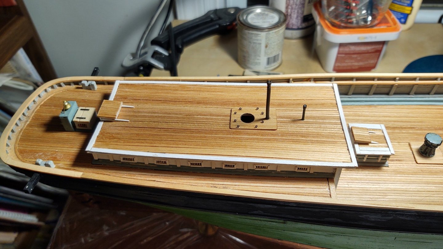
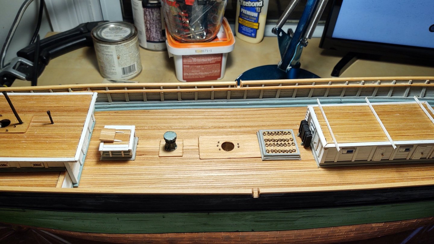
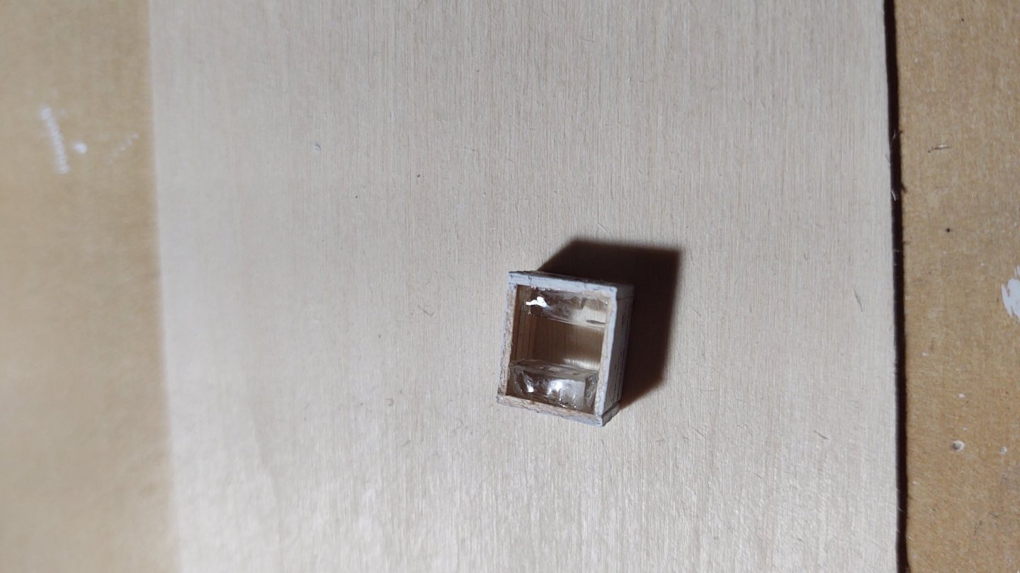
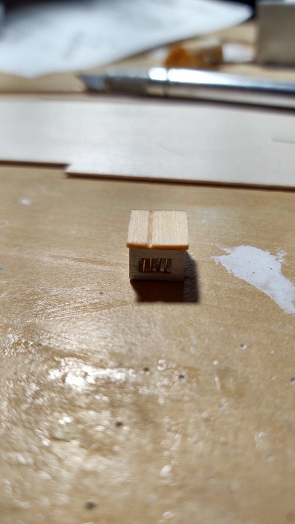
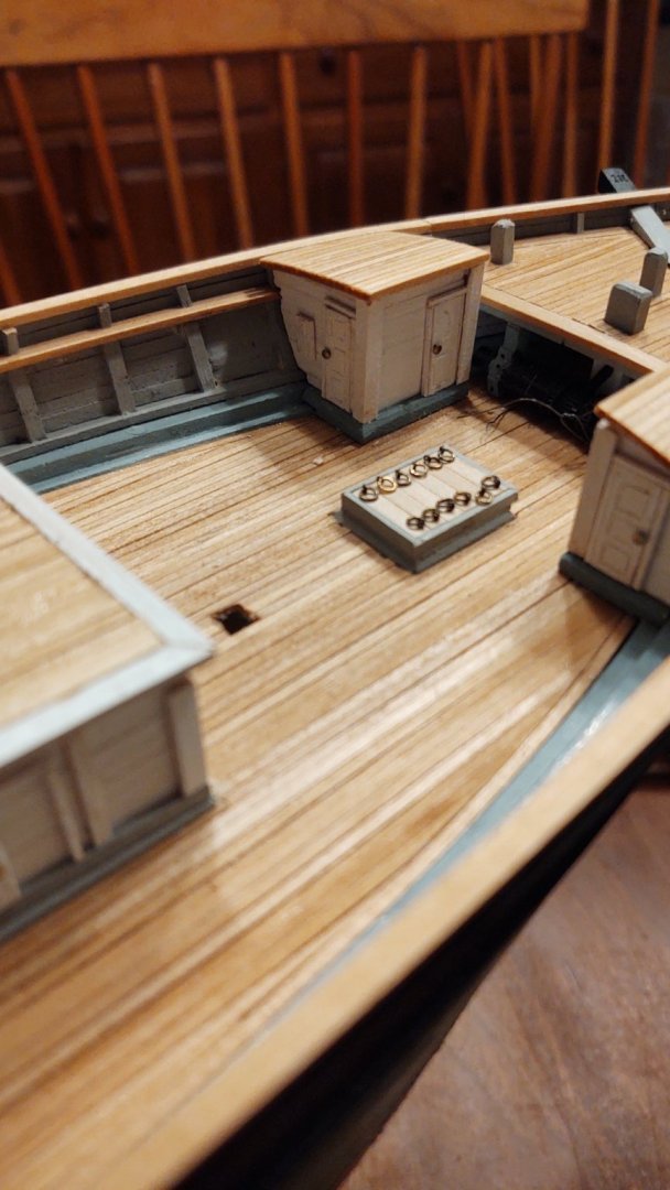
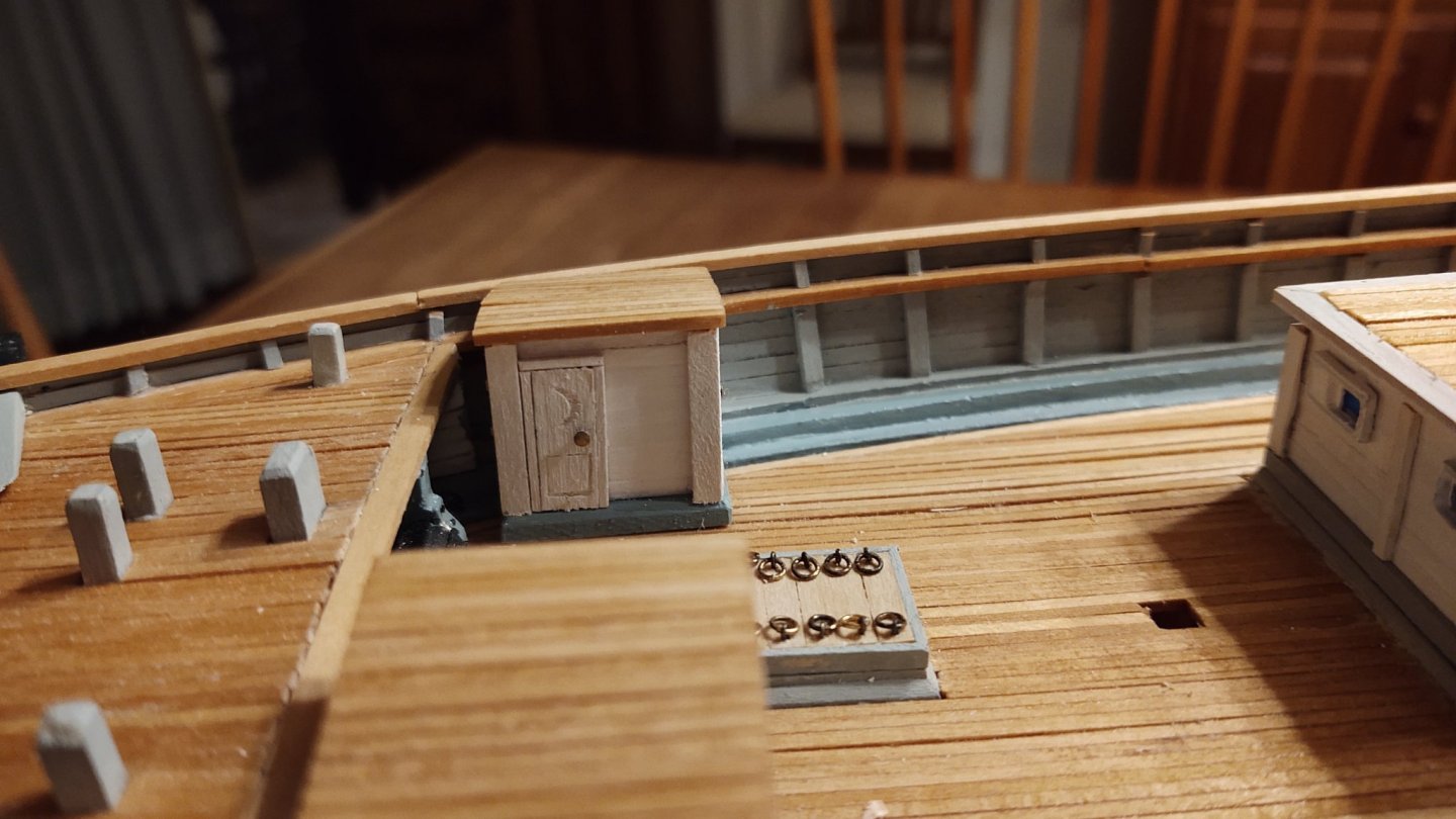
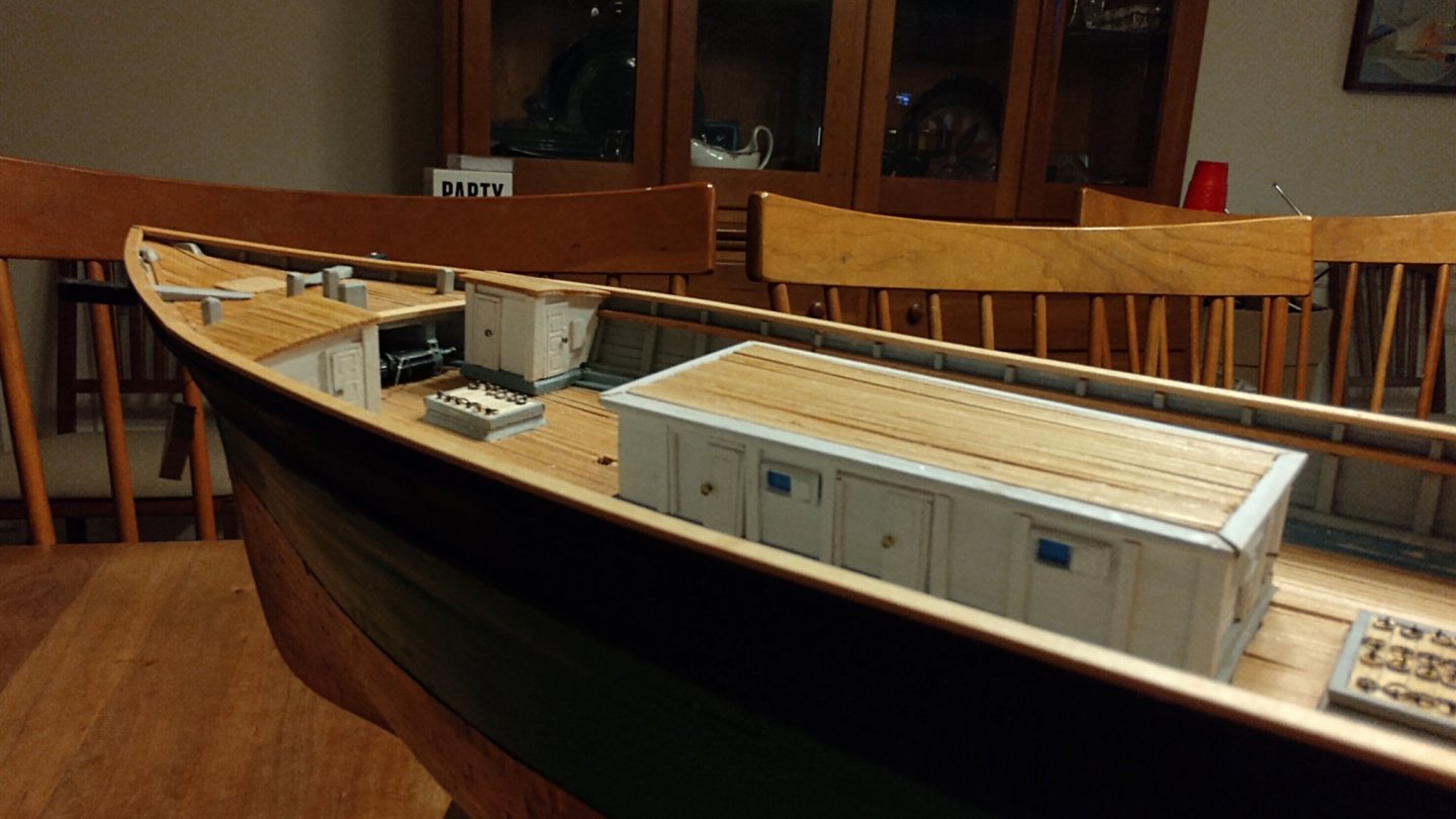
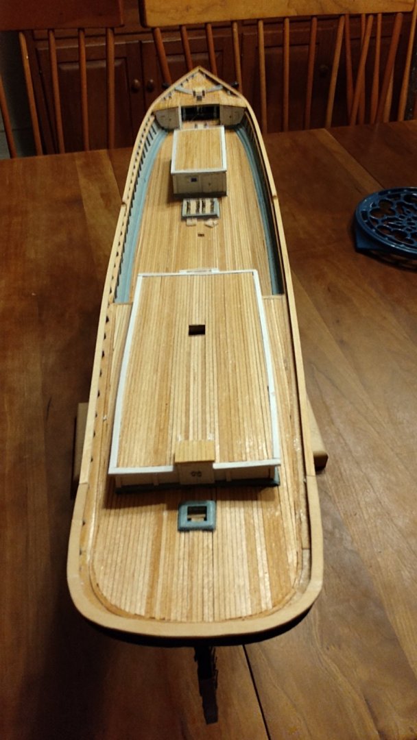
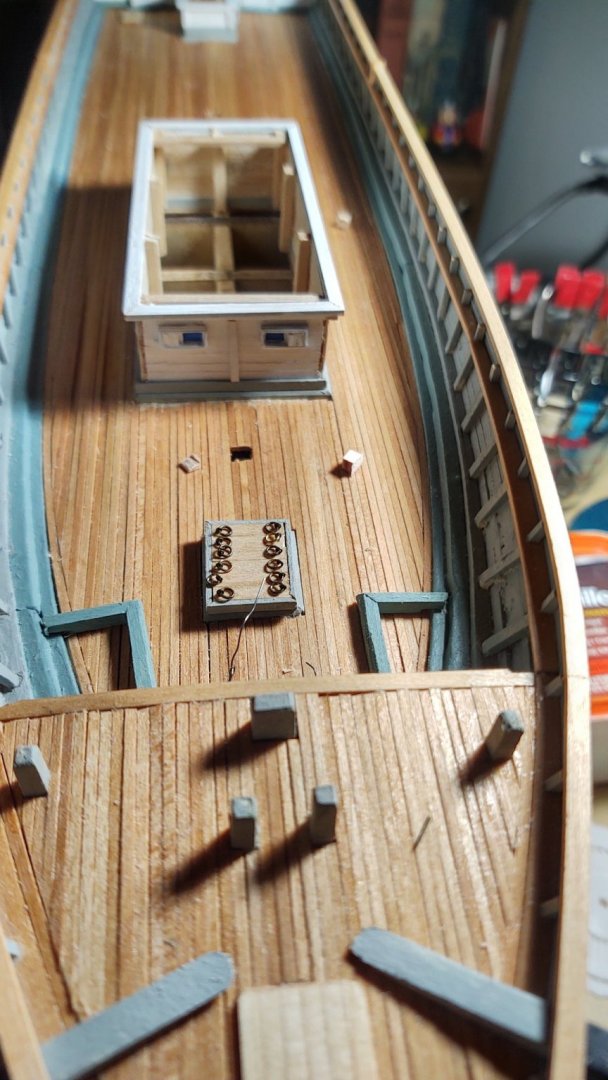
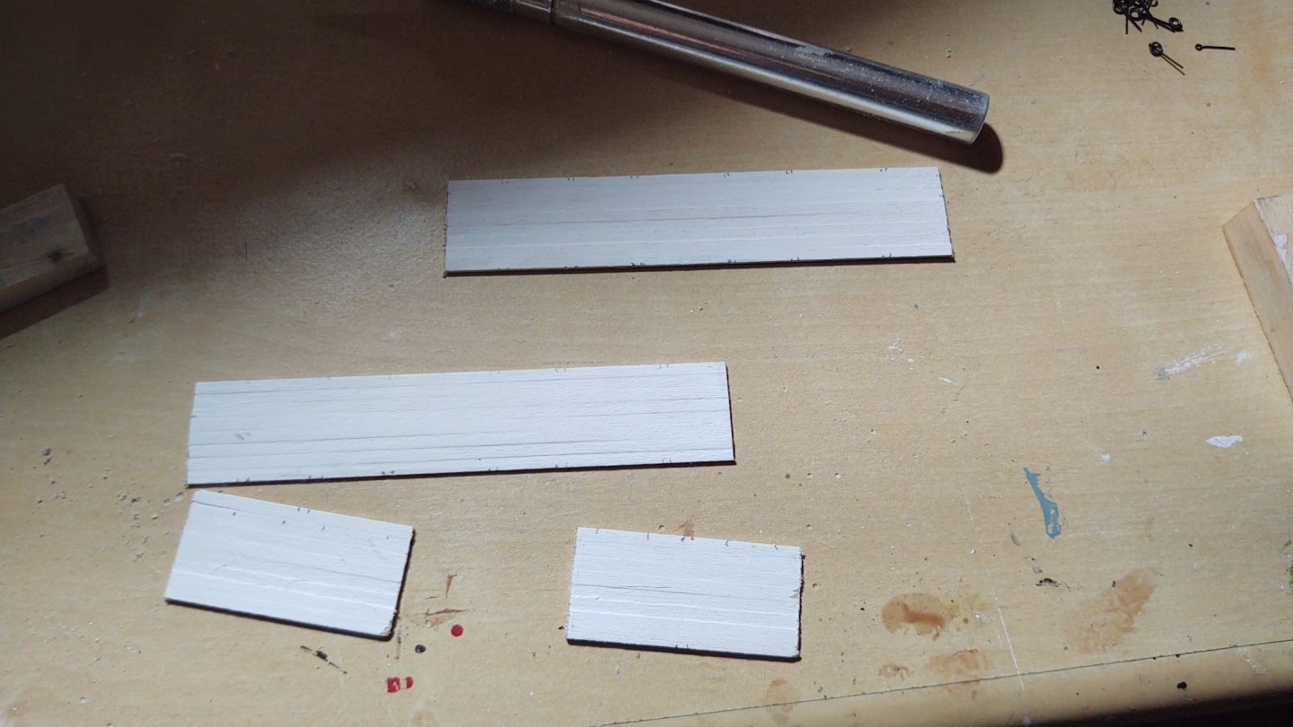
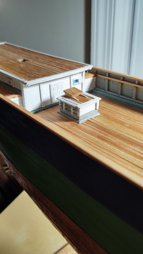
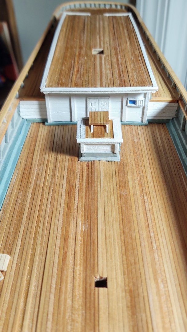
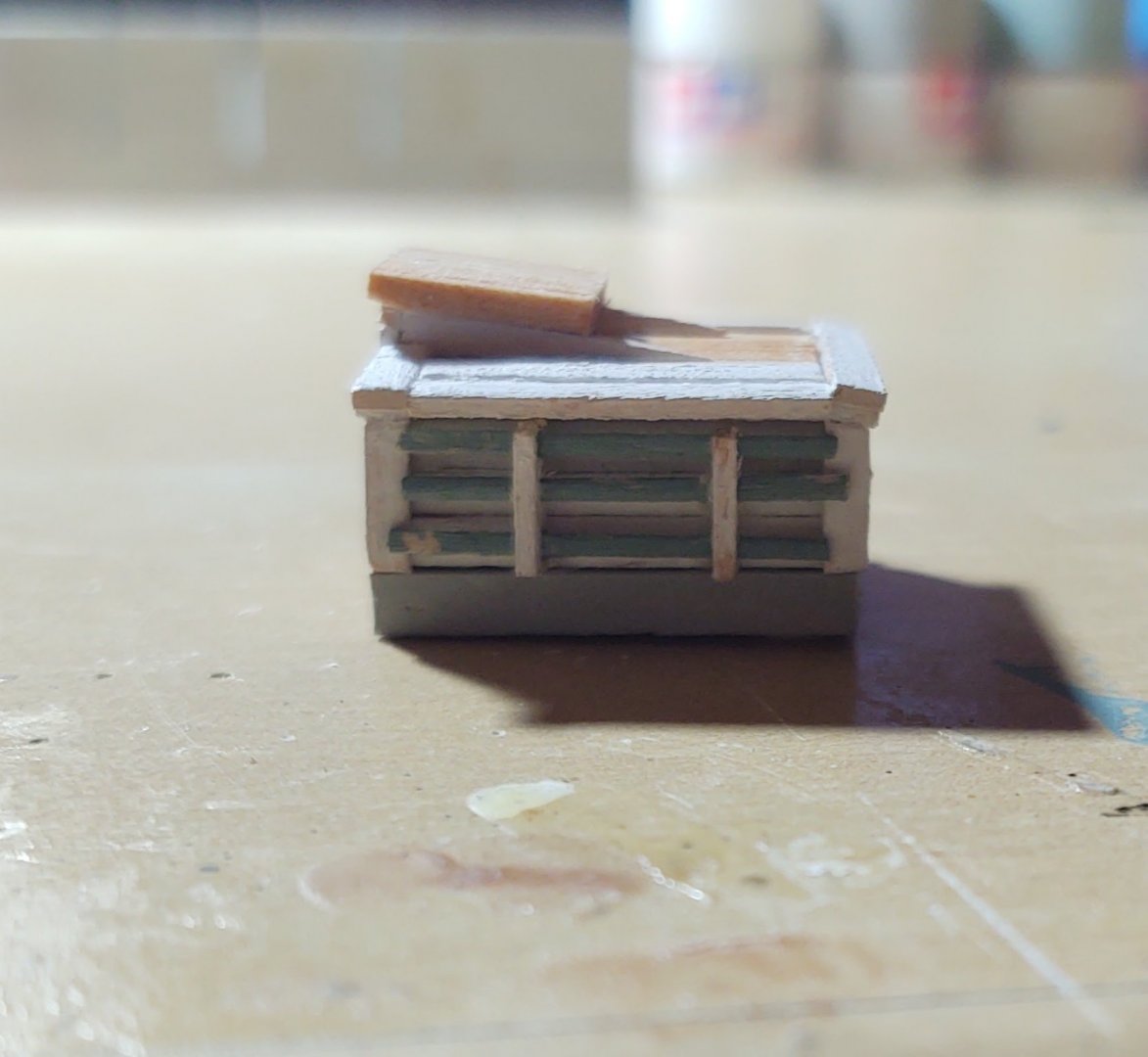
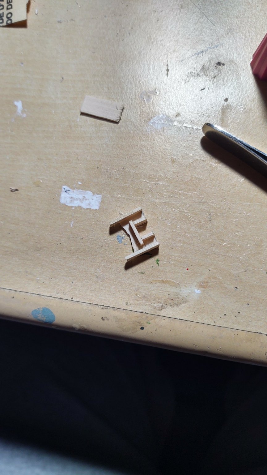
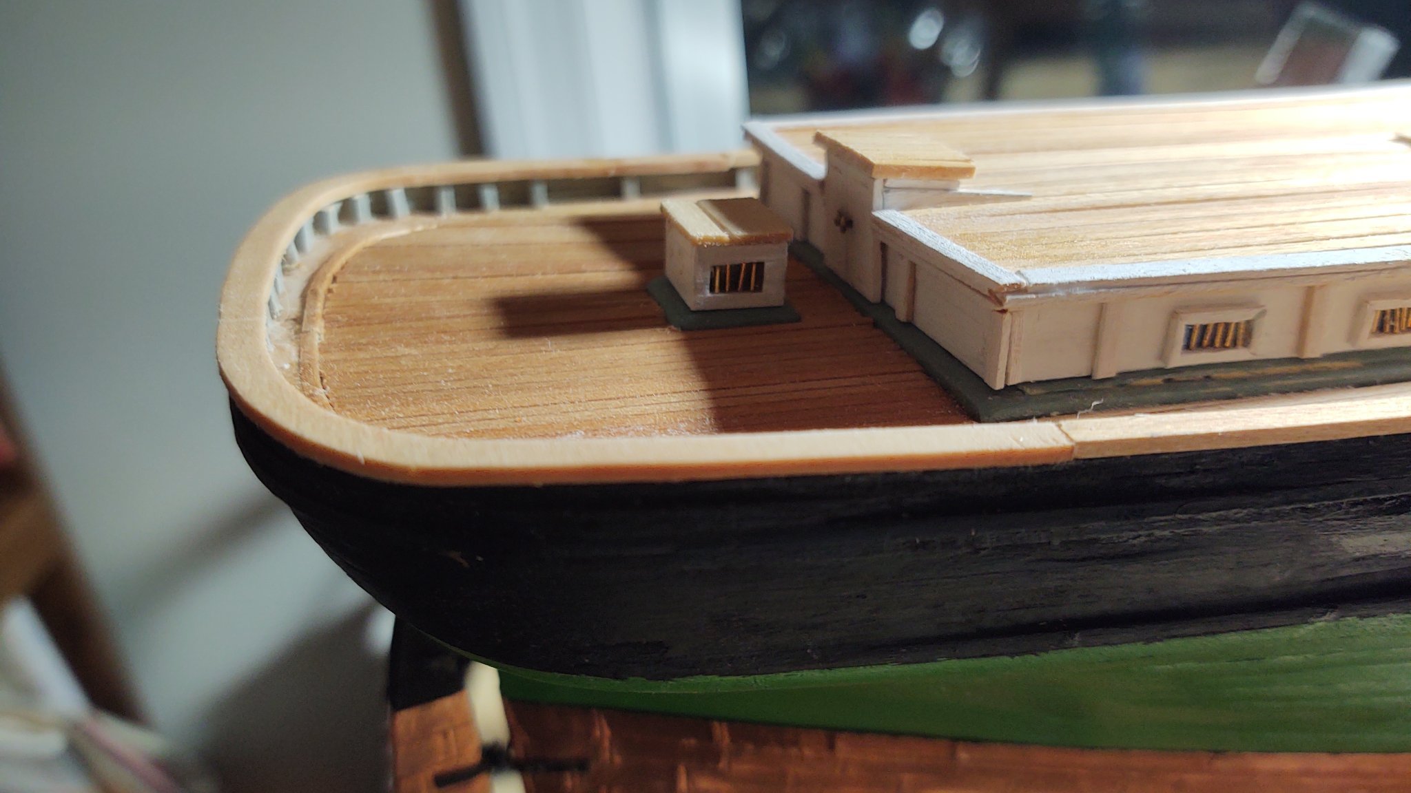
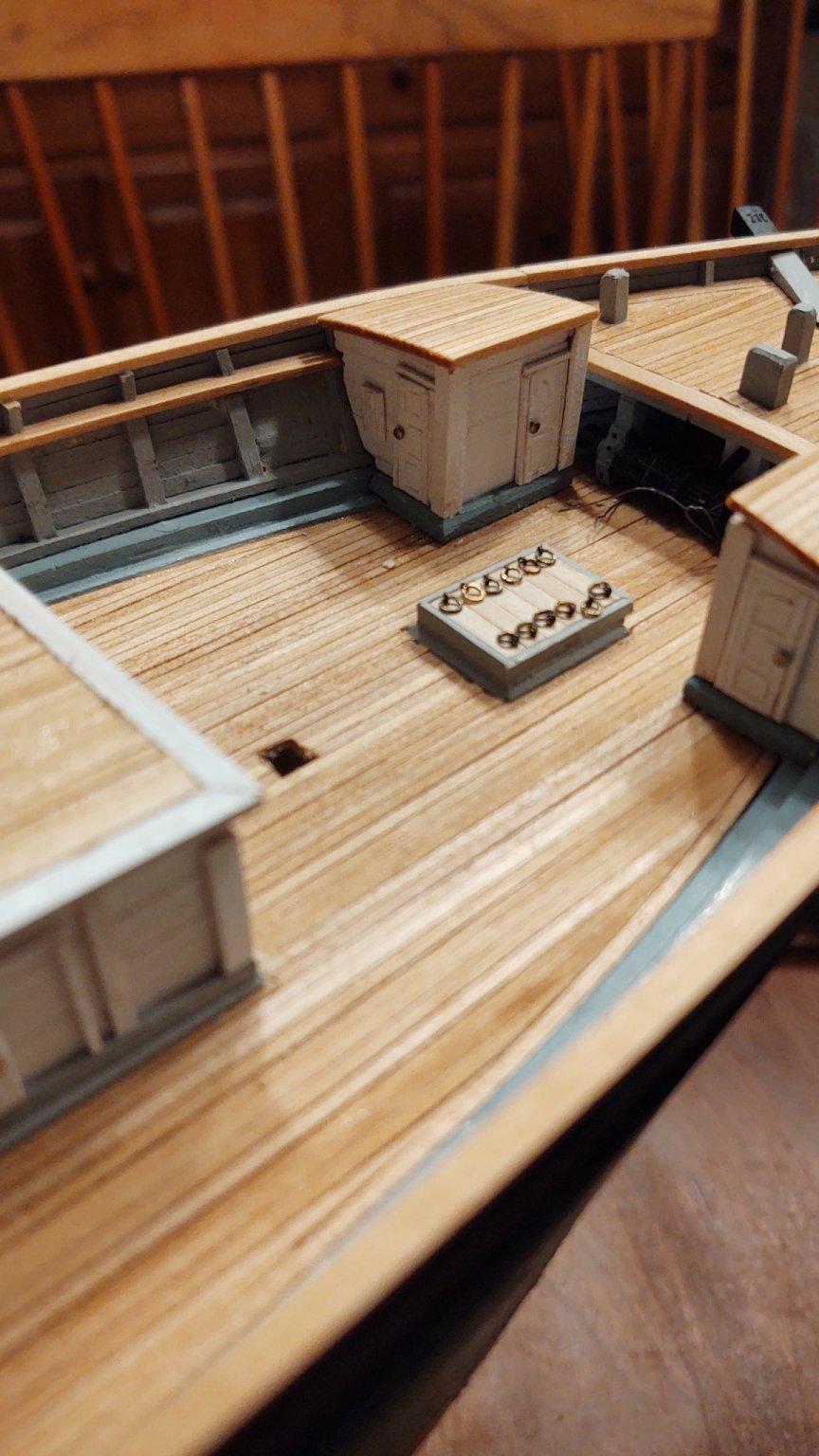
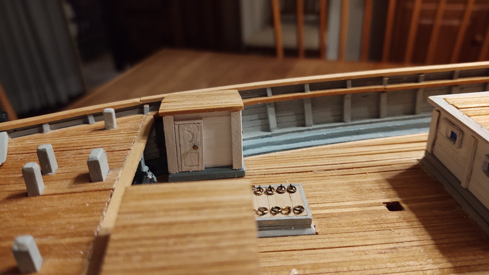
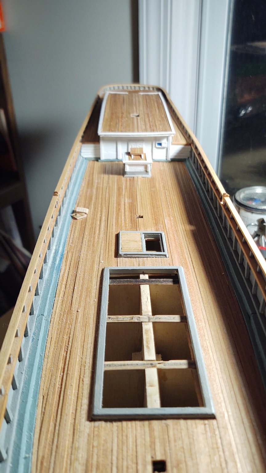
Okay, continuing with the deck furniture before tackling the cutwaters, naval hoods, and (yeek) trying to carve a figurehead. I've finished the water closet/storage/belowdeck entry structures forward (I'm sure there is a proper name and hopefully someone will be able to provide it). As with most of structures, I built them in place, using 1/8 square stock to make two of the corners defined by the coaming. I also mounted two small bits of scrap against the bulwarks to anchor the outer edges of the bulkheads. The bulkheads were built up, painted, and then trimmed to fit in the locations as required, and I built some corner fascia using 3/32 square stock that sanded to shape with my dremel. The hatches were all premade, excising bits with an Exacto knife to make the panels. Each hatch used 1/32 square stock to make the jambs and the lintels, and then the whole hatch unit was installed. The capstan bars were made from 1/32 square stock, embedded into their racks, and the racks mounted on the forward side (although they are next to impossible to see). The ceilings were made from 1/16 square stock (the same stock I stained for the deck months ago), joined, shaped and then glued into place (I'm holding the starboard side one down to let the glue cure in the upper photo). So, a couple of views of the completed units: While I realize that this is probably inauthentic, I couldn't help myself make the following for the hatches to the water closets: Childish, I know, but you need to have some fun in life. So this is what the ship looks like overall now from the stern. I've also mounted the rear hatches to the carriage house (for some reason I hadn't done so yet). So, I have one more hatch to make, and then I pretty much need to get this thing on its display board because it won't be much longer before I no longer want to set this upside down. I used wipe only poly for the cherry base board, which now looks fabulous, so that is done, however, a couple of questions to folks out there. I have three nice brass pedestals from BlueJacket, but they have very deep slots, so without some kind of change, there will be a gap between the keel and the bottom of the slot. Question, do people generally prefer to put some kind of spacer in the pedestal (i.e. a pice of wood the fills the gap, presumably painted brass) or do they try to cut the tops of the pedestals down so that the keel hits the bottom of the slot? If the latter, do you try to match the curve of the hull, or just cut off the top? If either of those, what is actually necessary to cut brass? I am not swimming in precision power tools (most of what I have is from the days when I was building play structures for my children (i.e. great for treated, dimensional lumber, not so great for precision miniature work); all four of the wooden ships I've built or are building were made with a single power tool - a dremel. Does Dremel make anything that can realistically cut brass? Thanks for the help, for looking in, and for the likes! Regards, George K.

- 602 replies
-
- 6
-
-
- Flying Fish
- Model Shipways
- (and 2 more)
-
Modern AIs that attempt to do this turn out to be almost laughably bad. There are some very old color photographs made by using 3 plates with color filters that can be used.to evaluate how well the AI works, and they tend to do poorly. It's not surprising really, it's like a mod function, there are multiple identical color schemes that will generate the same grayscale image, so how can you possibly reconstruct with the available data? George K
-
Depends on how you plan to do it. Once I start planking, I want to get it over, so I push to the end. Since I'm painting my ships rather than looking to have the bare wood finish, I worry less about needing a bit of putty or slight irregularities. Almost exactly a month from first to last plank, then additional time for the bulwark stanchions and bulwarks. It'll be done before you know it! George K
-
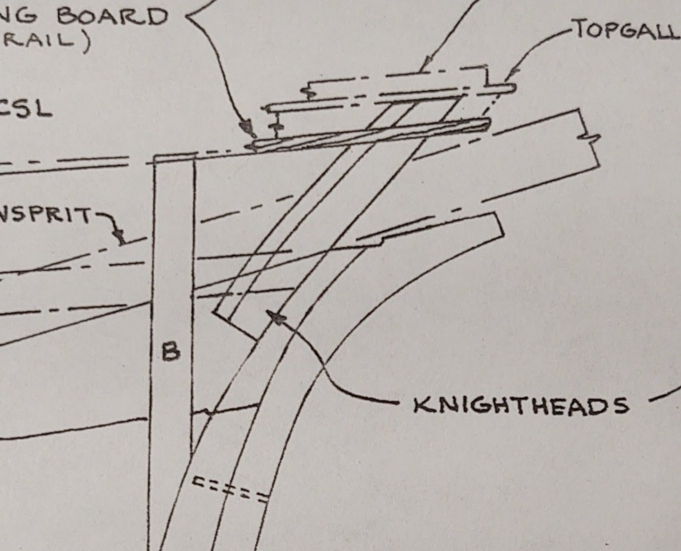
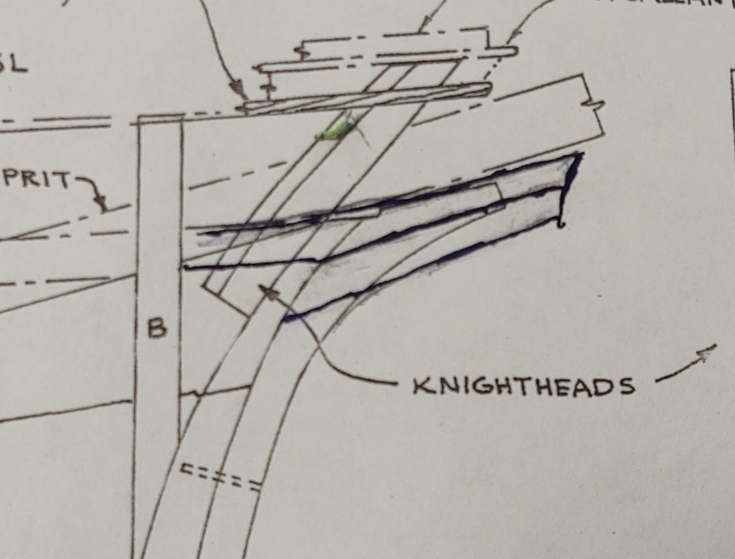
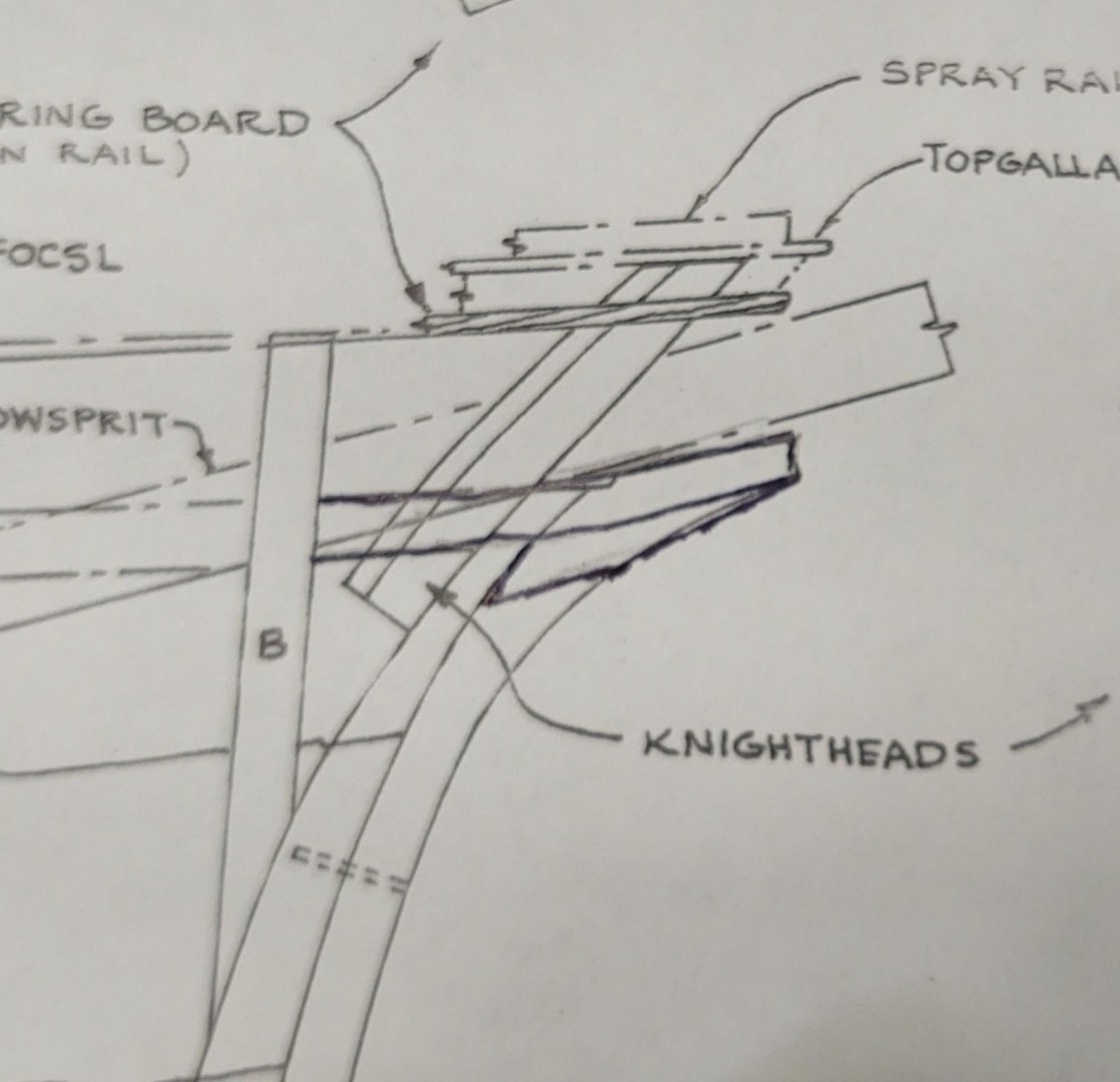
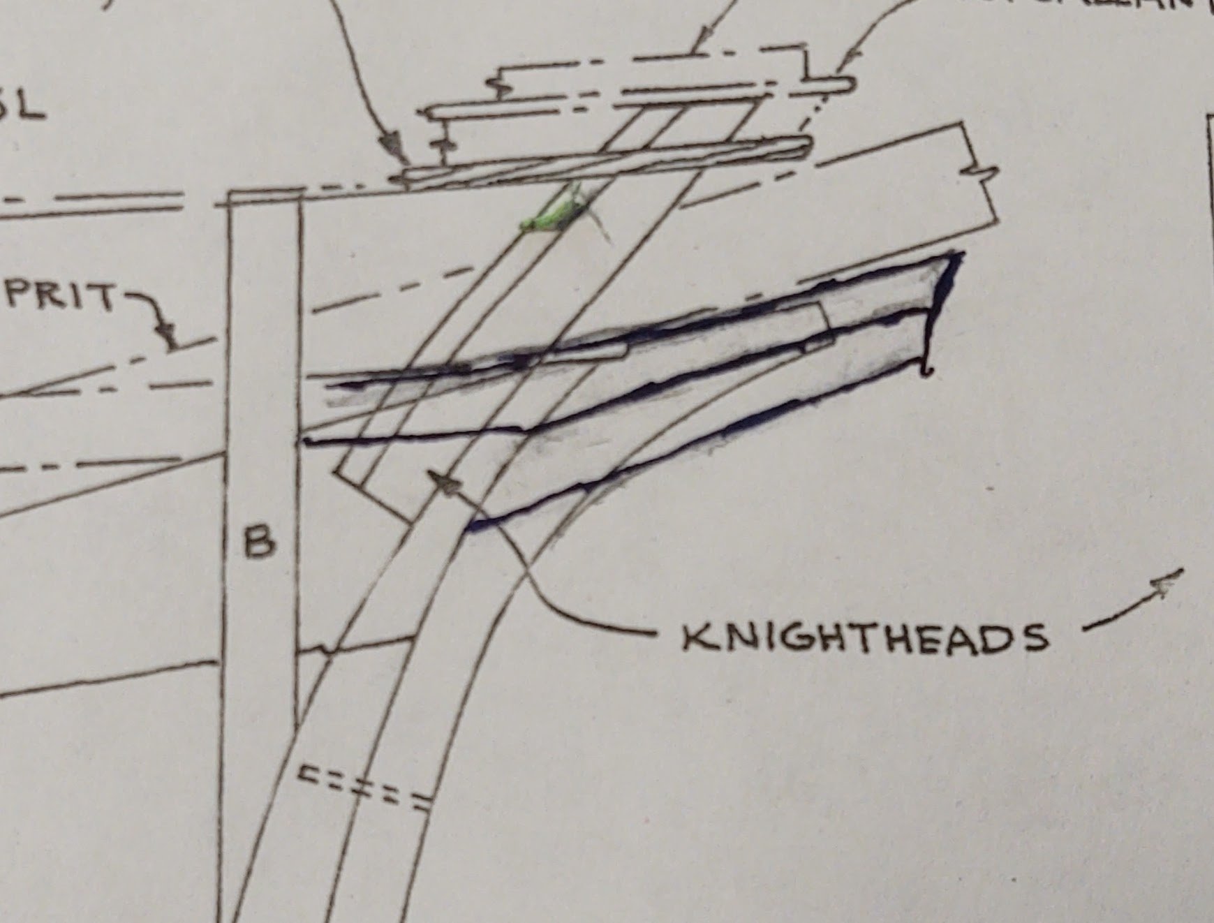
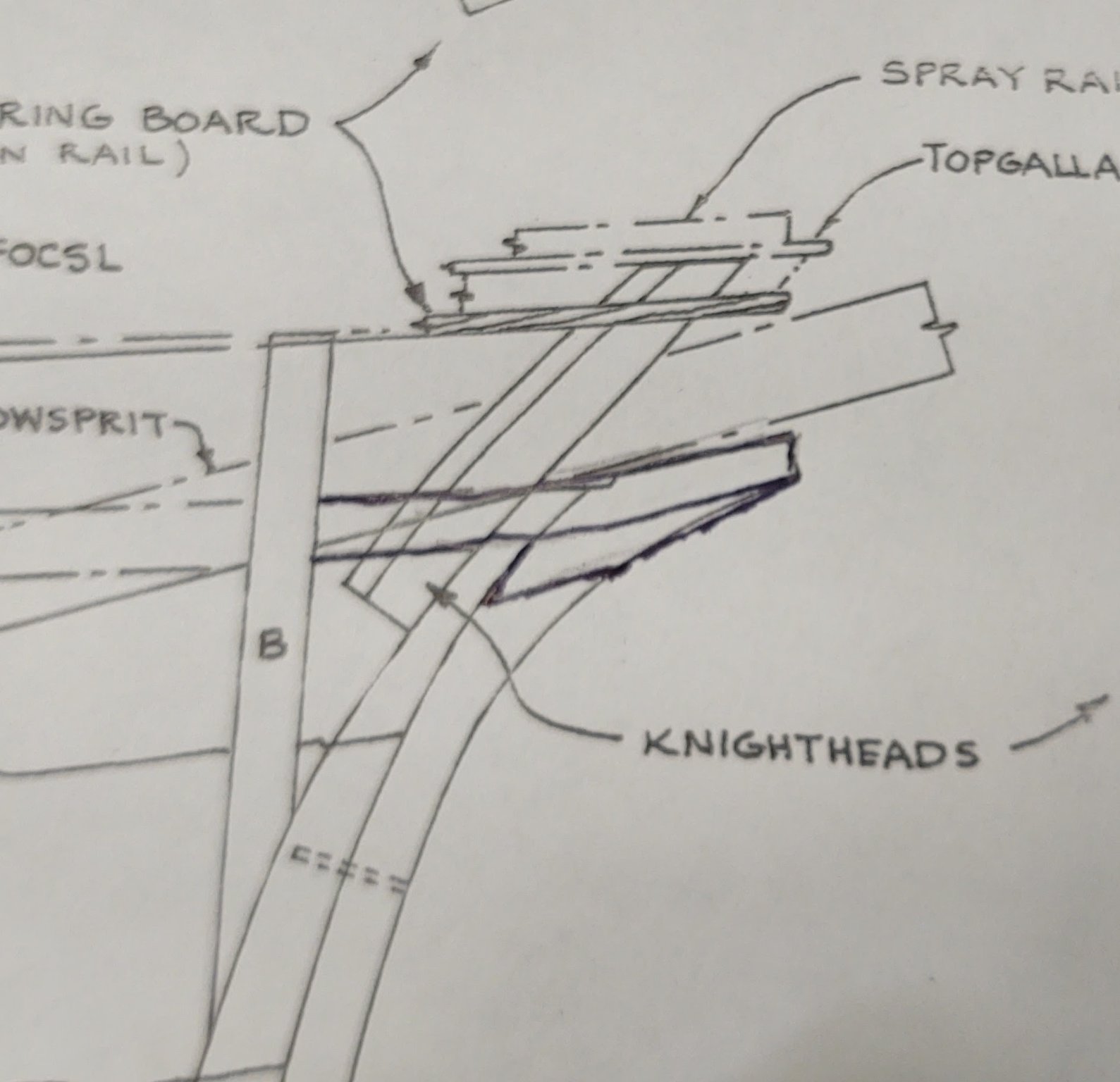
@ClipperFan or anyone else that knows. Following up on your previous post, I'm a bit unclear about how the cutwaters and naval hoods fit into the scheme of the stem. So here is a section of the plans that shows the stem. Apologies in advance - I'm not an artist, but do the cutwaters and naval hood simply brace the stem (making it thicker but not longer) as below: or do they brace and extend the stem as in the below: And if the latter, i assume that the void that is under the extension is filled? Or is the issue that the stem as drawn is too short, and needs to be extended and reinforced by the cutwaters and naval hoods?
- 602 replies
-
- 1
-
-
- Flying Fish
- Model Shipways
- (and 2 more)
-
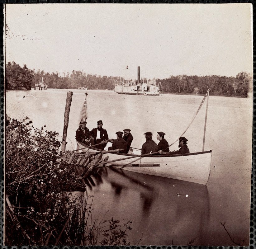
Not the clearest photo and not of a City class but compared to the white hull, I'd say the oars were bright. Ship is the Commodore Perry. From the URL below. https://www.digitalcommonwealth.org/search/commonwealth:wd376x76z. I think that makes sense, everything about the City class was done in a hurry. Anyway, your mileage may vary. Probably getting old hearing this, but the build is absolutely awesome. George K
-
Adding these parts seems eminently doable. All of the other examples I have seen tended to have decorated cutwaters, is there any indication how the Fish was set up? That is a much nicer flying fish, it's a good model to try to carve something. Way better than the pretty pathetic figurehead castings that came with the kit
- 602 replies
-
- 3
-
-
- Flying Fish
- Model Shipways
- (and 2 more)
-
I thought people might find this article from Atlas Obscura about steam bending planks for the replica Gotheborg II to be interesting. Puts some perspective on our steam bending problems... https://www.atlasobscura.com/articles/18th-century-steam-boxes-gotheborg-ship?utm_medium=atlas-page
-
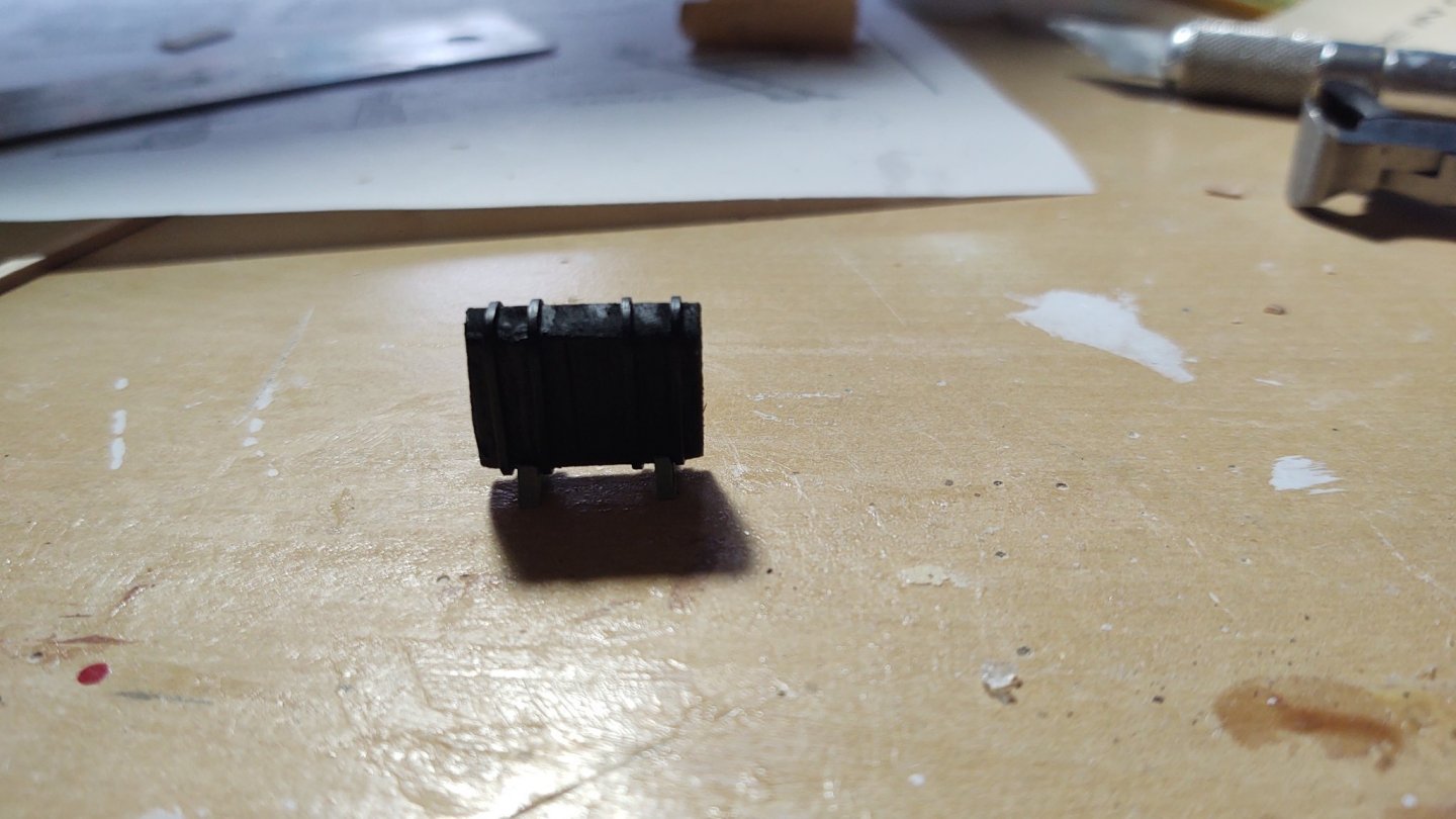
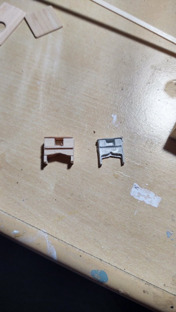
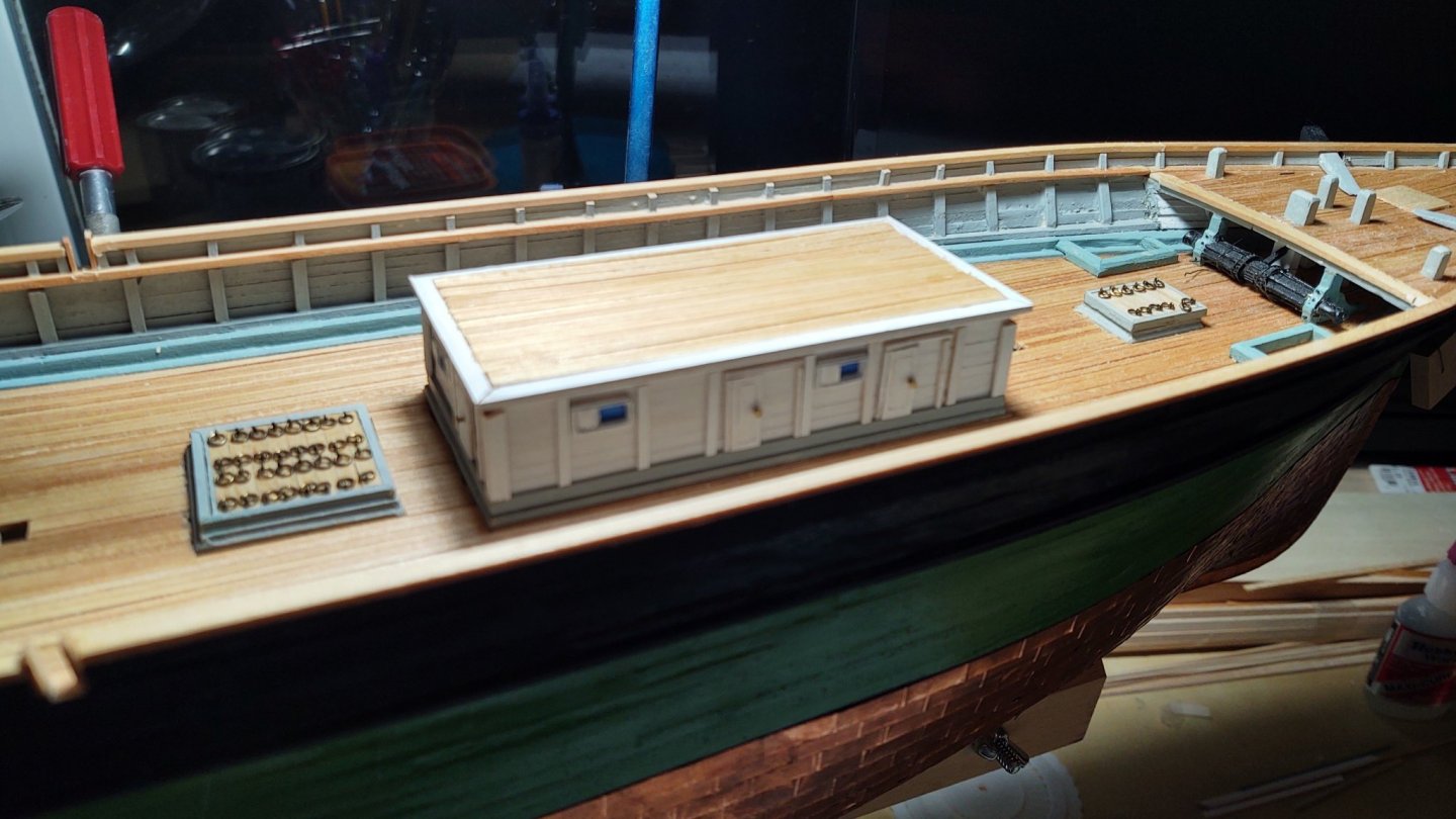
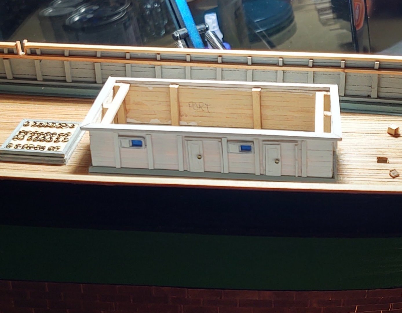
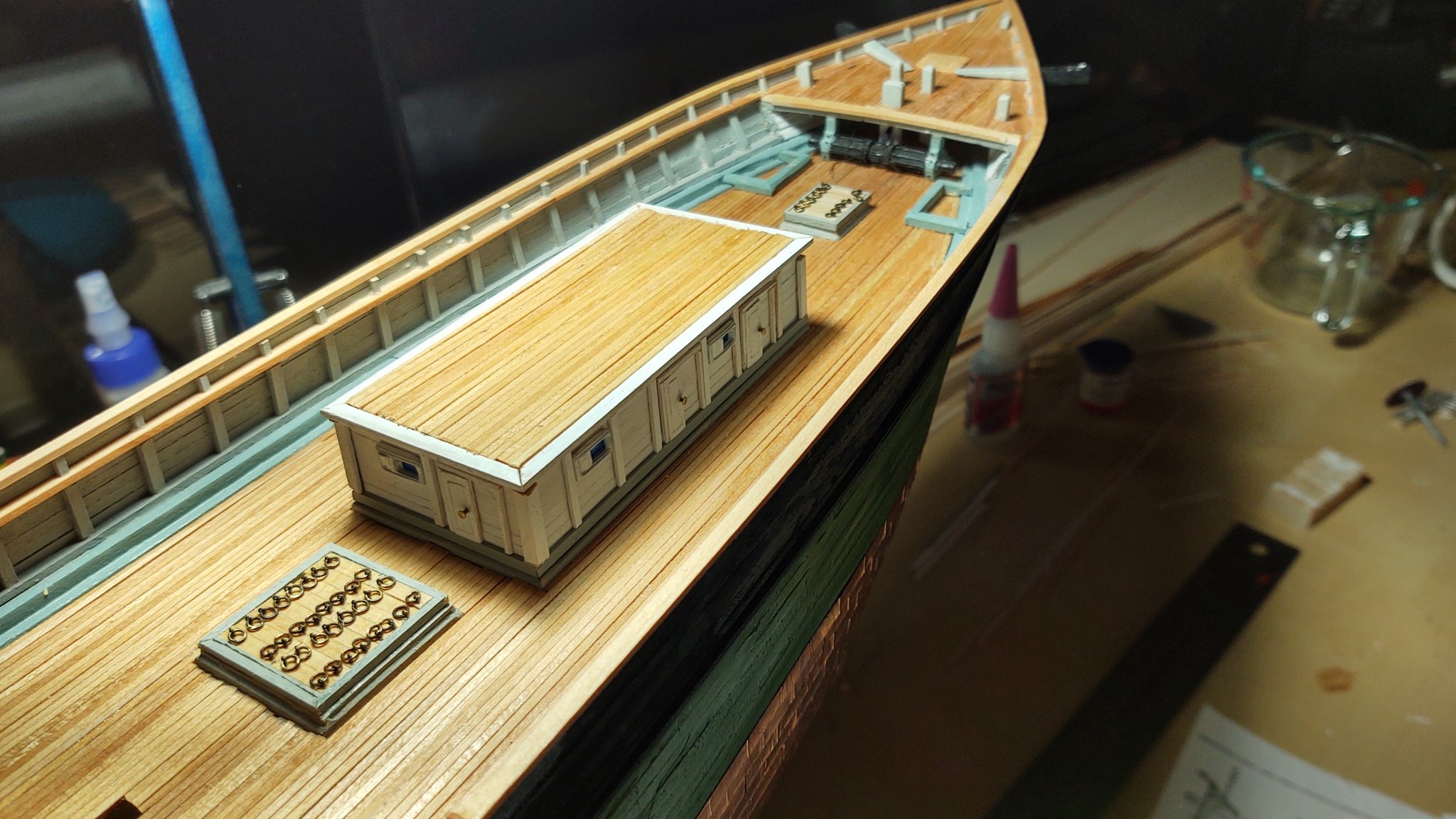
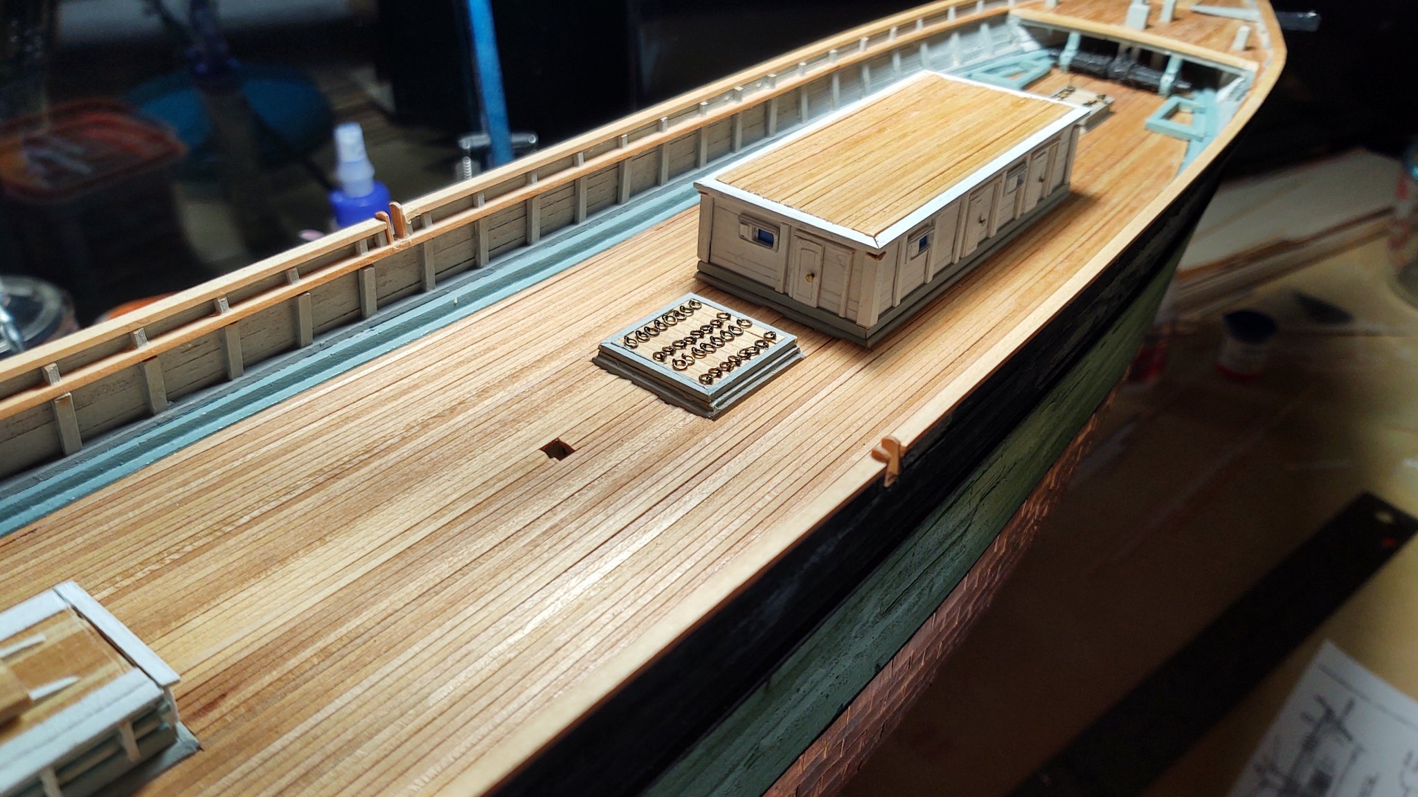
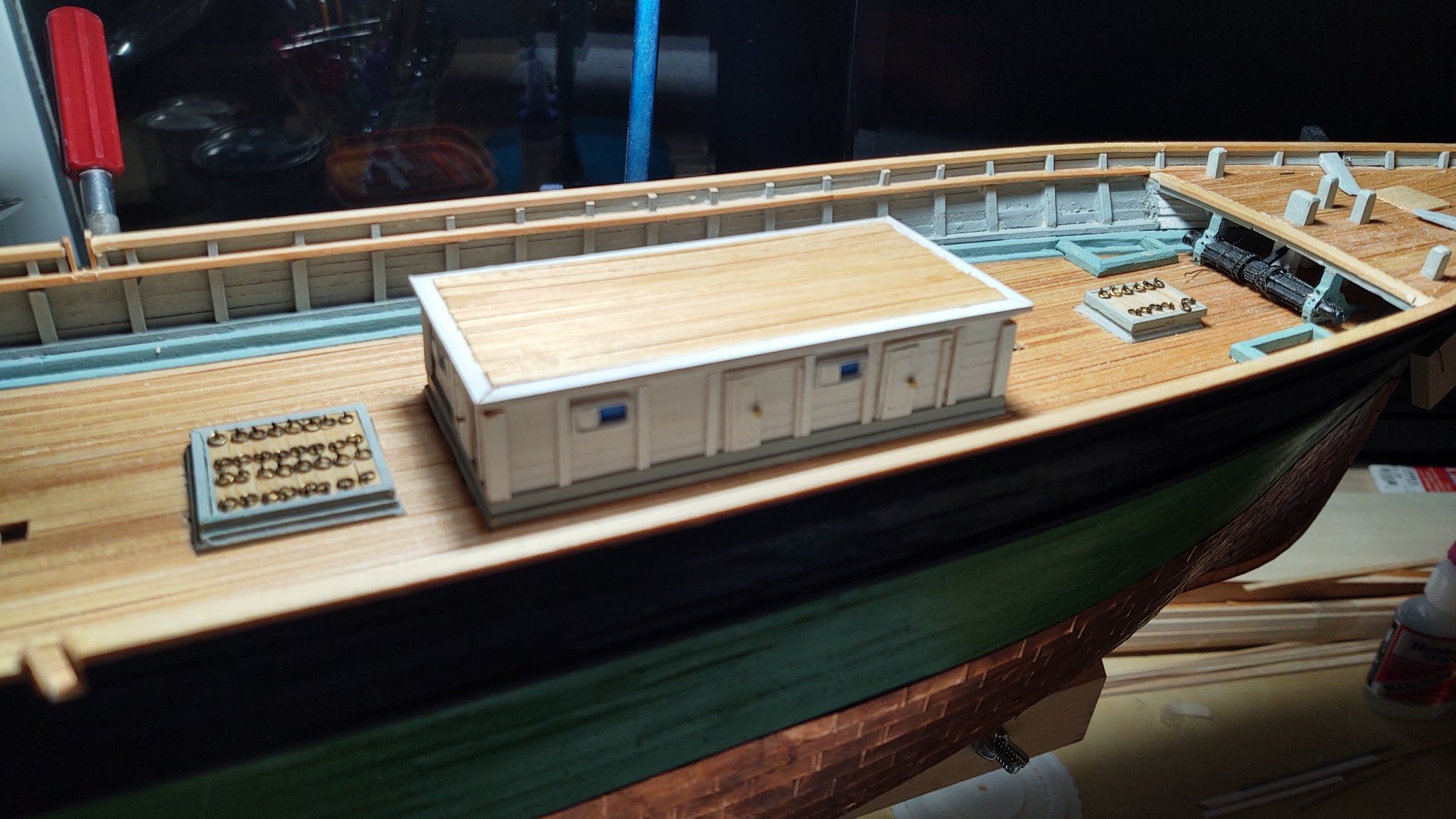
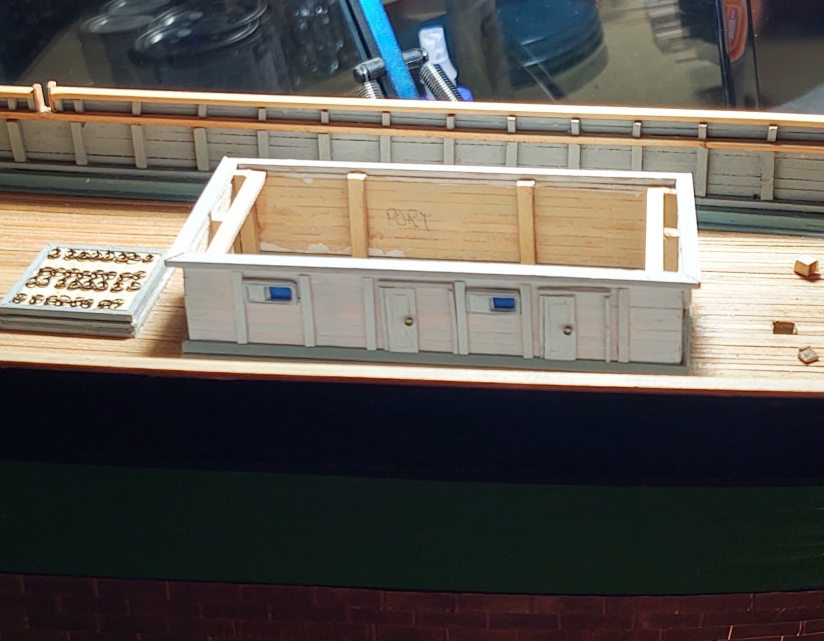
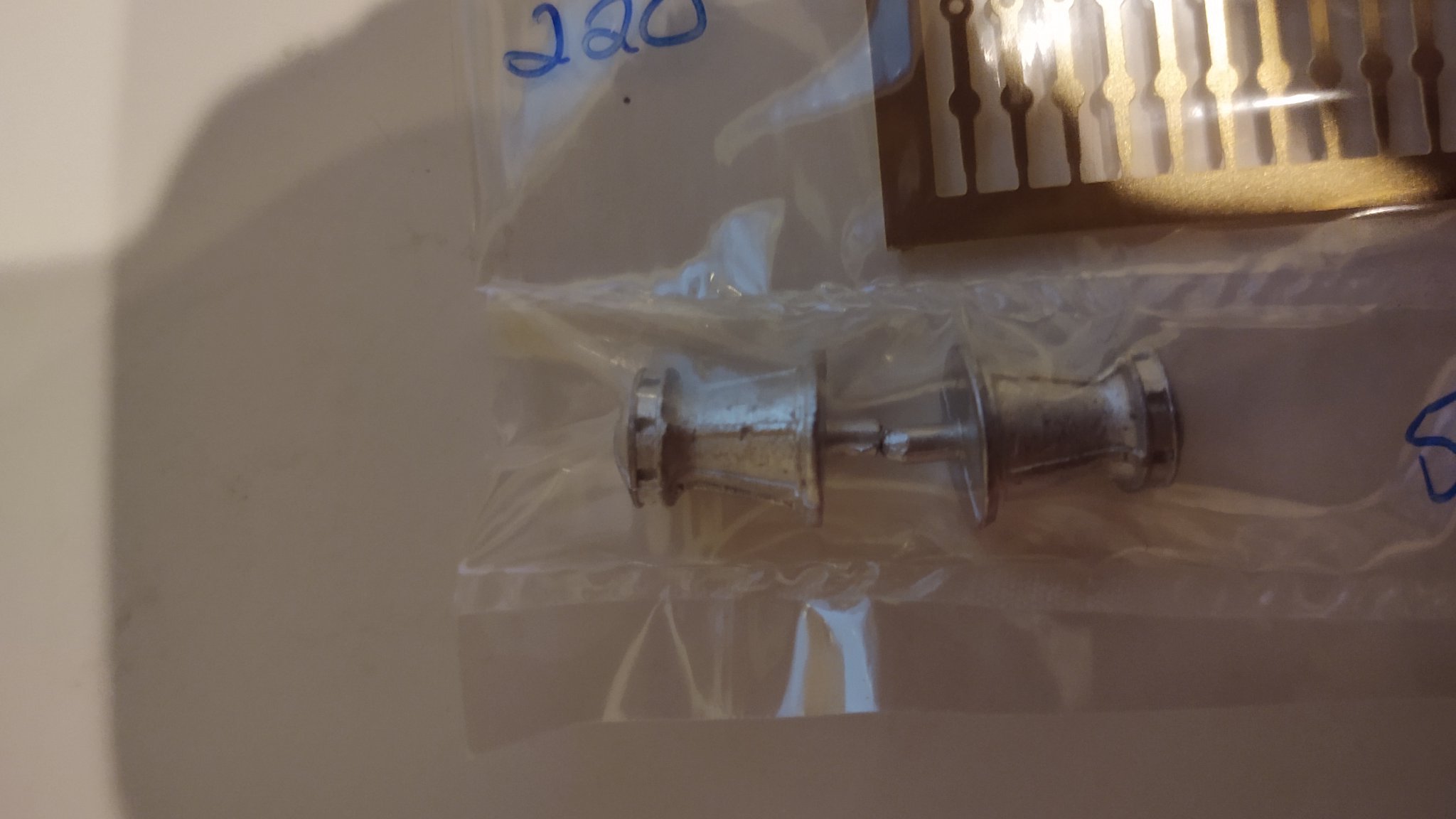
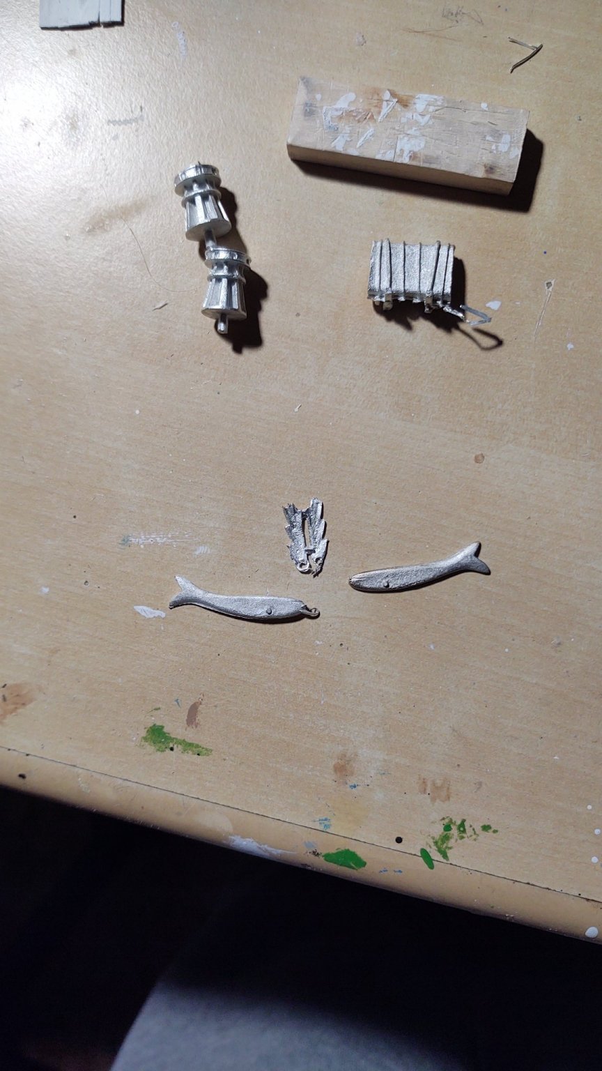
Well, the main cabin is in place. As I mentioned earlier, I built it in situ rather than building it separate and installing on the deck. You saw in the earlier post how I built up the cabin bulkheads. Before installing the bulkheads, I put the port frames with the sliding covers in place, then mounted the bulkheads on the frames, and then added the decorative elements using pre-painted or pre-cut wood. For the sliding doors, I cut wood of the correct size, incised the panel marks and then painted them. The knob is a nail cut off near the head, and the door frames are mad from pre-painted 1/32 square stock painted white. I generally built up an entire door and frame first (so door, left jamb, lintel and right jamb) and mounted them as a unit. A 1/16 x 3/32 piece of boxwood, prepainted white was used to make the upper level of the decorative trim (with the 1/16 facing out), and then a 1/16 by 1/8 frame was placed on top to mark where the ceiling would be installed. The ceiling is the same 1/16 square stock I stained for the deck months ago. The progression is shown below: So, two images of the ship showing the situation as it currently stands in a slightly broader view. You will notice that I have also completed the forward cargo hatch, and mounted the water closet coaming and will start building those soon. Because I am getting near to this point, I have a couple of issues that I want to bring up. As has been said a number of times, the castings for this kit are really awful. Fortunately the pump is not bad, but I have a suspicion that I'm going to replace a bunch of the castings, including the capstans, fife rails, and the figurehead. Just for reference, here are the capstans, water tank and the figure head. The capstans don't look too bad, but the tops are a mess. The water tank is genuinely horrible and the figure head is, I don't know ho to even say it. I was able to get some replacement capstans from Bluejacket (see below), but I'm afraid I'm going to have to try to carve a fish, and replace the water tank. With regards to the water tank, does anyone know if the tank was iron or wood? I could see reasons for either, but just don't know - if it's wood I'll probably paint it buff or brown, if iron black, and mount it in the blue of the coamings either way, I just don't know. Also, there is a ladder on the after side of the deck house, does anyone know if they would have been wood or iron in 1854? I have some nice scale lumber from Midwest that would make a good wooden ladder but I guess I'll try to make it out of brass strip if it was iron. As always, thanks for looking in and for all of the likes! Regards, George K


.thumb.jpg.448c76ae04d7946243c9ead80e785761.jpg)


- 602 replies
-
- 5
-
-
- Flying Fish
- Model Shipways
- (and 2 more)
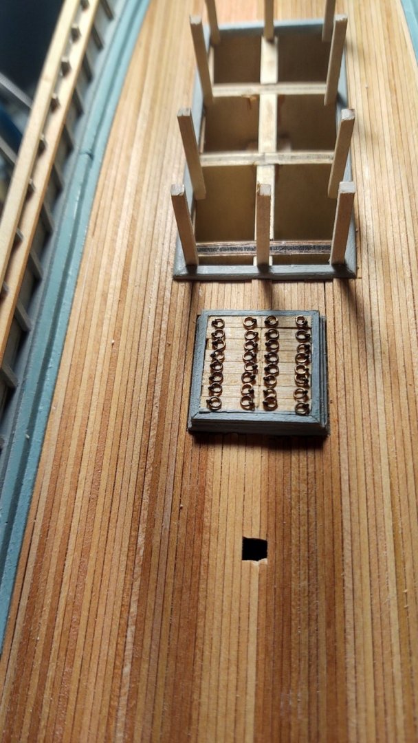
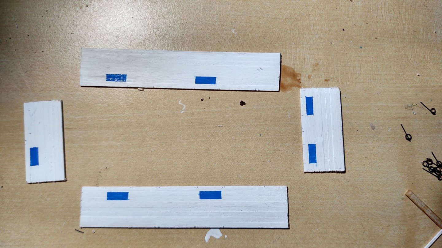
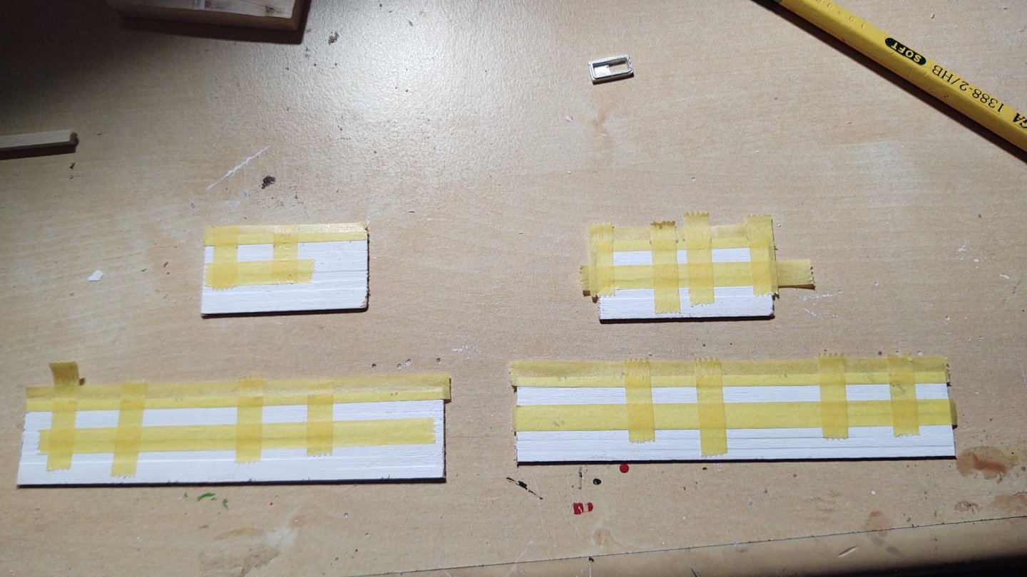
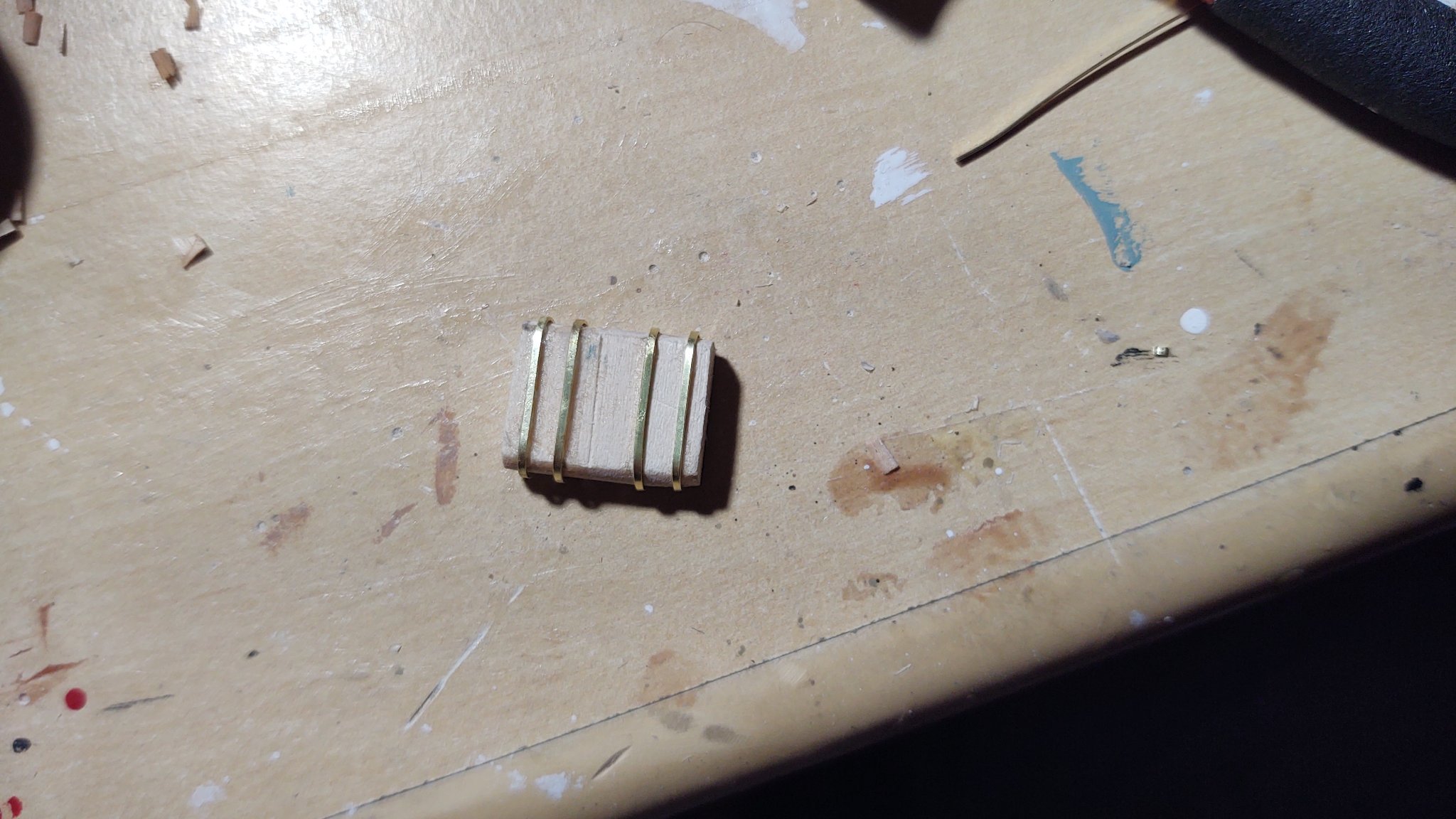
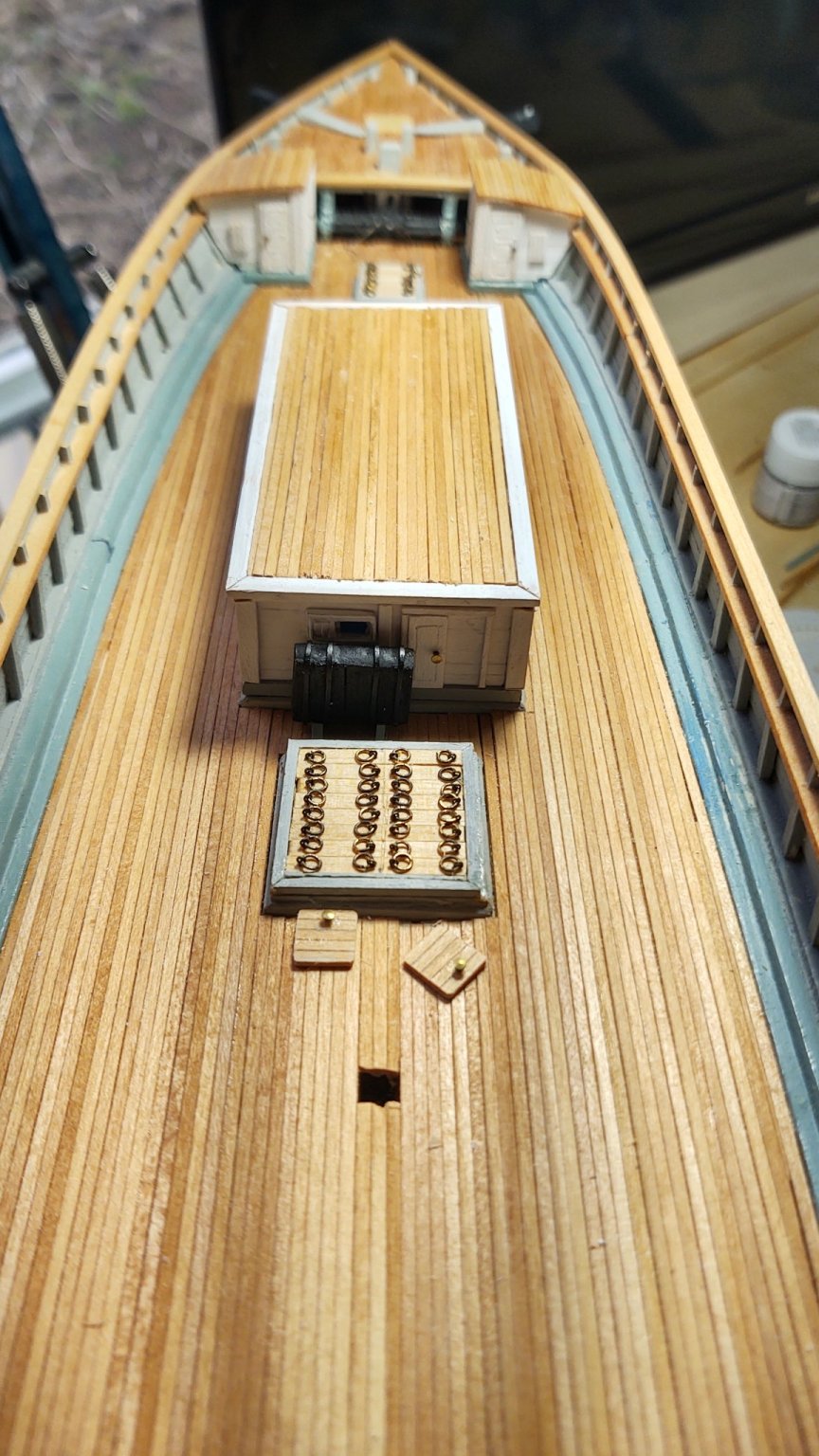
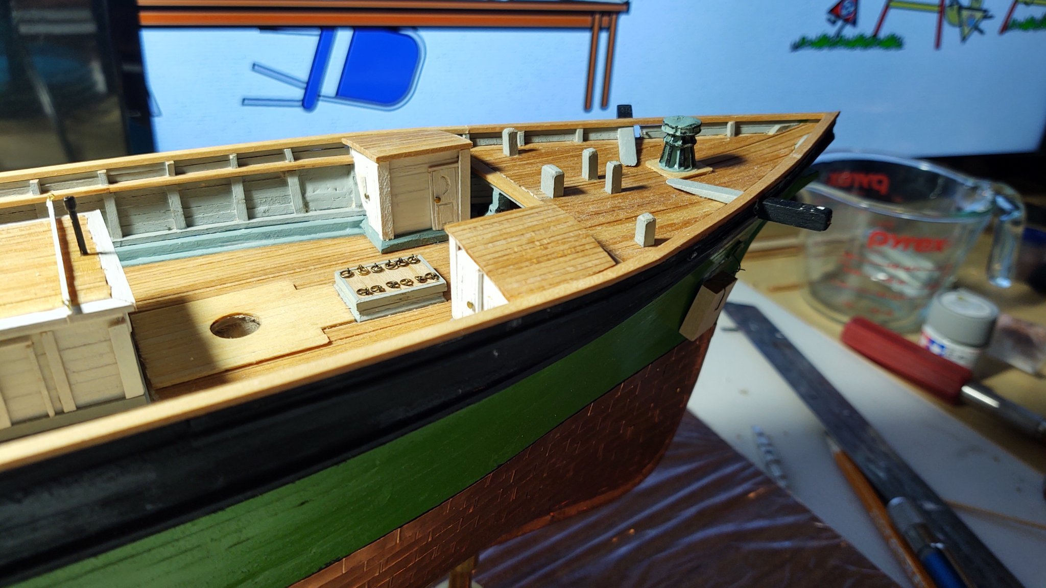
-
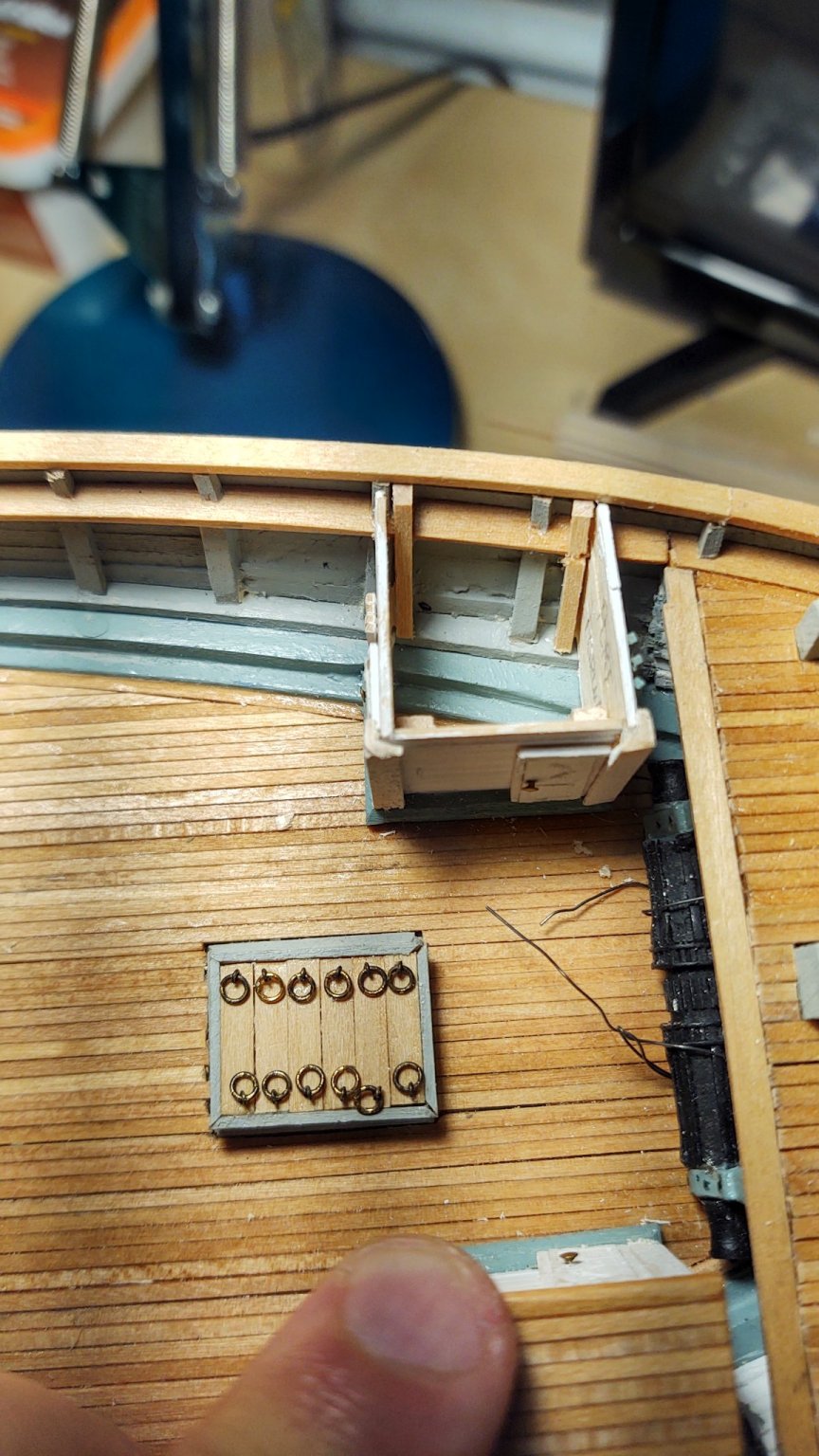
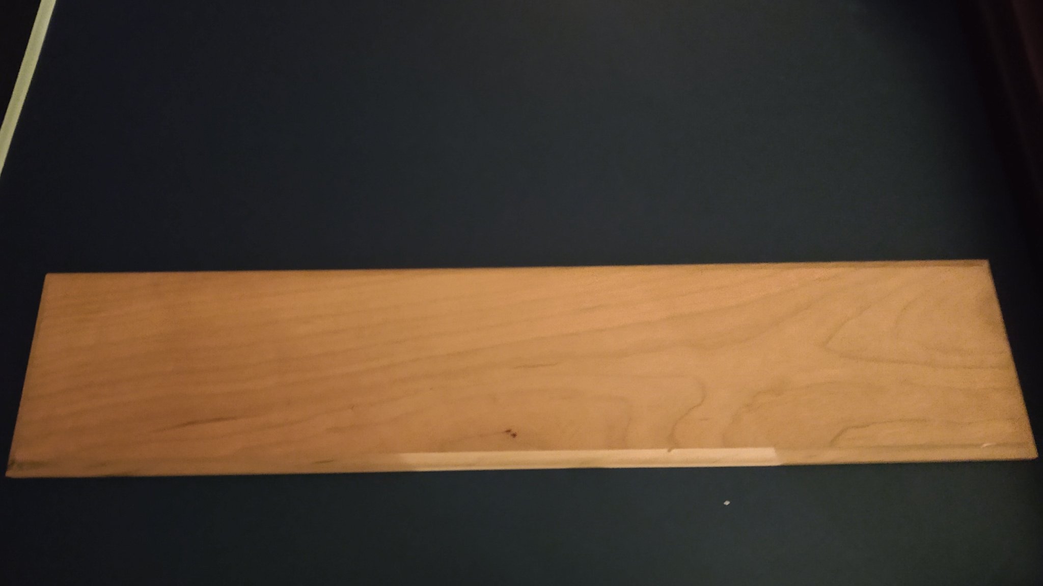
A brief update to describe progress in the last several days. If you looked at some of the earlier pictures, I had started putting the covers on the main cargo hatch, and had recently realized that I hadn't built up the entry way enough from the coaming. So, I added the additional vertical supports, made the hatch covers and attached the lifting rings. The latter were made from some leftover split rings and small eyebolts from my Niagara. That complete, I started on additional deck furniture moving forward. As with the carriage house, I've decided to build it in situ rather than making a separate piece and mounting it on the deck (as I did with the booby hatch). For some reason, I like the latter better. As before, step 1 is to set up a set of internal frames that are going to support the bulkheads (some of them visible in the photo above, and then to build and prepaint the bulkheads themselves. As with the carriage house, the area under the ports is painted located, masked, and painted blue. The sliding port covers (a mix of wood and a Britannia casting) have received one coat of paint, they can be mounted over the painted regions seen below once they have a second. Here are the masked bulkheads, and with the port areas painted on: In the latter, the sections are (clockwise from top) port, forward, starboard, aft (both the fore and aft have down facing right, whereas the P/S pair have "down" facing in. As with the carriage house, once the bulkheads are in place, I'll add pre-painted decorative trim, and then the overhead. While that is going on, I've also started on the water closets, which will also be built in situ. In this long shot, you can see the cargo hold, the framed up cabin, and the coamings for the WC. Neither are yet glued into place, hence the port side one is a bit out of kilter. Finally, I received a beautiful cherry baseboard from BlueJacket today. Once it is properly finished and the cabin and WC's are in place, it will be time to transfer from my building frame to the base board. I have three brass pedestals (also from BlueJacket) that should allow it to have a nice solid, stance on the board as it becomes time to put on the final rails and start the various spars. The photo doesn't really do the base board justice, it's a really nice piece of cherry with lovely grain. When I do mount the ship I think I'm going to wrap it in saran so that it's protected from drips and the like. As always, thanks for looking in and the likes. Regards, George K


- 602 replies
-
- 6
-
-
- Flying Fish
- Model Shipways
- (and 2 more)
-
Welcome aboard! There are now four of us working on the Fish. George K
- 60 replies
-
- 1
-
-
- Flying Fish
- Model Shipways
- (and 1 more)
-
Deck furniture continues. The booby hatch is built and mounted. A couple of quick views off the ship, with capstan bars in place: and in situ on the ship. I've ordered a baseboard, it's getting to the point where I want to get it on the board before I do too much else as I don't want to have to turn it over to drill the holes for the pedestals once anything truly fragile is on the deck. As always, thanks for looking in and the likes. Regards, George K

.thumb.jpg.86b0c33580dbc1ff47c6cba10adb7f98.jpg)
- 602 replies
-
- 5
-
-
- Flying Fish
- Model Shipways
- (and 2 more)
-
Looking forward to seeing your construction technique.
- 3,560 replies
-
- 1
-
-
- clipper
- hull model
- (and 2 more)


.jpg.69be26493ae2096ce9126df0d2c176cc.jpg)


.jpg.66b757b052b2637fa6546b6d8e4e8b74.jpg)


.jpg.64ca685342f4b8f74a8607fdc2b6e013.jpg)