HOLIDAY DONATION DRIVE - SUPPORT MSW - DO YOUR PART TO KEEP THIS GREAT FORUM GOING! (Only 75 donations so far out of 49,000 members - C'mon guys!)
×


gak1965
-
Posts
722 -
Joined
-
Last visited
Content Type
Profiles
Forums
Gallery
Events
Everything posted by gak1965
-
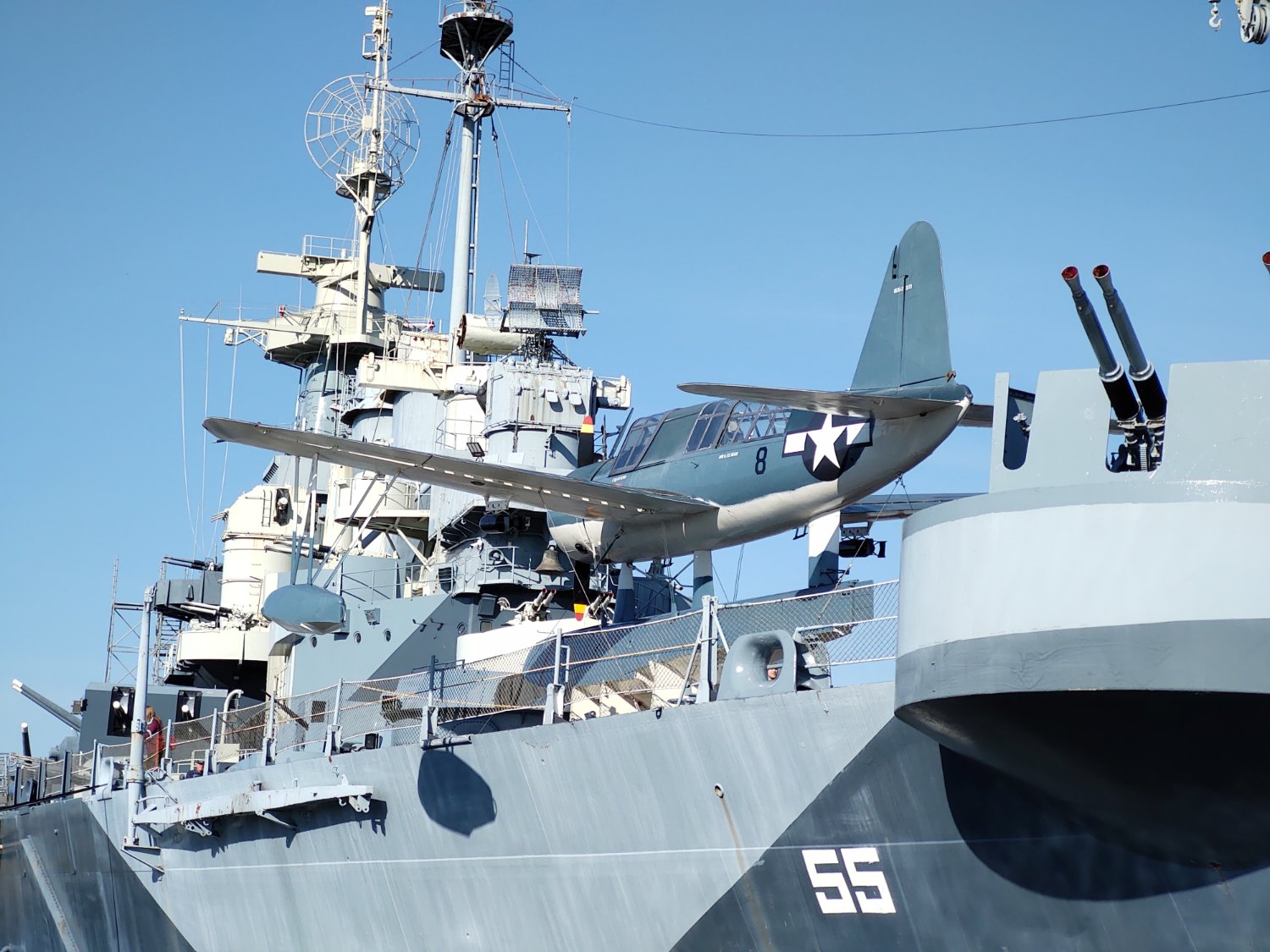
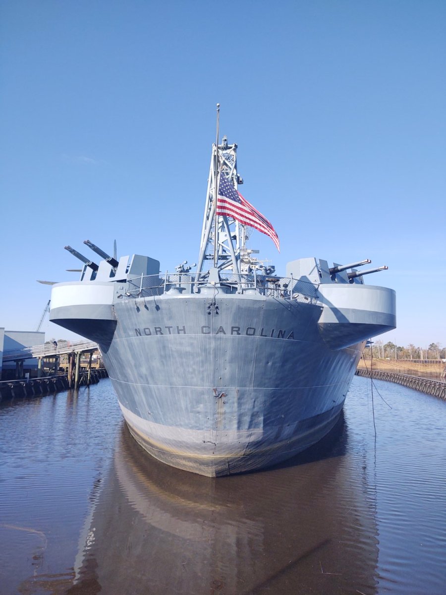
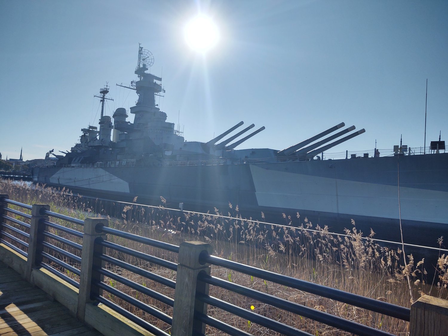
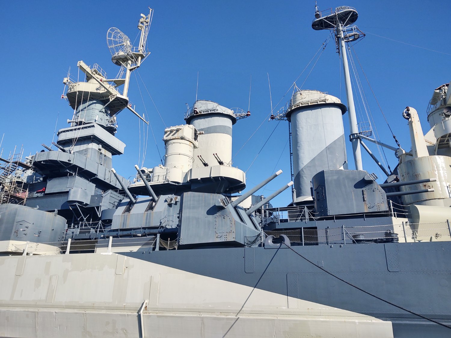
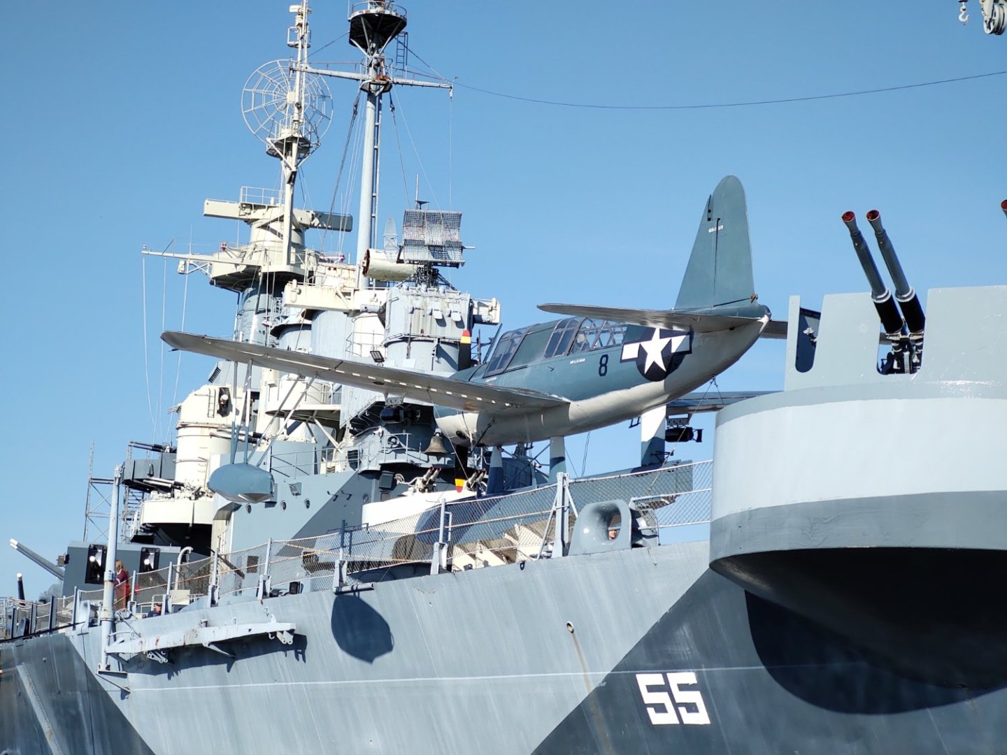
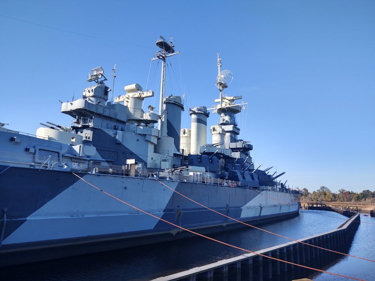
 Well, back from everything, hopefully back in the shipyard soon. In the interim, here's a palate cleanser. The triathlon I did was the Ironman 70.3 Wilmington, so here are some snaps of the USS North Carolina, BB-55, our first treaty battleship (the race ends just across the Cape Fear River from her and is nicknamed 'From beach to battleship')
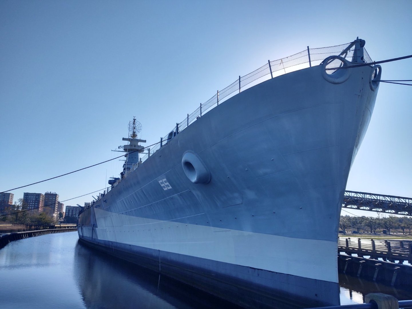


- 602 replies
-
- 3
-

-
- Flying Fish
- Model Shipways
- (and 2 more)
-
This happens to everyone, more or less always. There are always things that need adjustment, often due to the manufacturing process, not error. My (and everyone else's) Niagaras had an issue where if you follow the instructions and plans you will wind up with improperly fitting cannons. Fortunately, I saw a build log and could adjust. You said you are fairing with files and chisels. I think sandpaper would work better The wood is softer than you think and it generally doesn't require that much fairing. At my limited skill level, anyway, I appreciate the fact that sandpaper limits the amount that I can remove at once. A rotary tool is useful when you need to remove a ton of material (e.g. in filler blocks), but most places you probably want something that removes wood more slowly (and goodness knows I've thrown away pieces I've hand sanded into oblivion) For the cutwater, I wound up adding it after planking with no I'll effects, although you could do so at any time during the early stages of the build. In retrospect, I might have added more filler, but as I'm the only one that will see it, c'est la vie.
-
Those shackles are amazing!
-
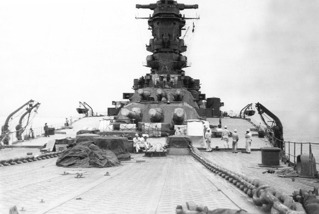
Ted (my apologies if I misunderstood your handle), I'm curious if the Nichimo Yamato has what @Roger Pellett called the "rather humpbacked sheer" of this class. The picture on the Anatomy of the Ship cover you put in shows the apparent downward slant from the after to the more forward of the forward turrets, and here is a public domain pic of the Musashi showing what I'm asking about . My grandfather built the Nichimo version in the late '60s, but I don't remember this at all (and it seems less than obvious on photos of the 1:10 model at the Yamato Museum), but I haven't seen the results of his build since the early '90s. Just curious if my memory is wrong or if this is one of the changes that was made with some of the newer kits or if some of the aftermarket parts make the change if I'm not misremembering. Please don't take this as a comment on your build, which is looking great, and which I am following with interest. FWIW, I've trolled ebay for Nichimo Yamato's but have just balked at the prices, and, for sentimental reasons I might get go for the Nichimo version over the new MRC version. Regards, George K
-
A trailboard is a decorative piece of wood, often (but certainly not always) with the ship's name, usually attached to the cutwater. As @ClipperFan can provide details for, there is every reason to believe that the Flying Fish had a set of Naval Hoods, which unlike a a trailboard are structural elements. He has shared a reconstruction/diagram in several of the Fish build logs of what the hoods (and the prow generally) would look like based views of other McKay clippers, particularly Glory of the Seas. Regards, George K
- 34 replies
-
- 1
-
-
- Flying Fish
- Model Shipways
- (and 1 more)
-
Welcome to the Flying Fish (and I suppose McKay clipper) club! It's always nice to see another Fish. George K
-
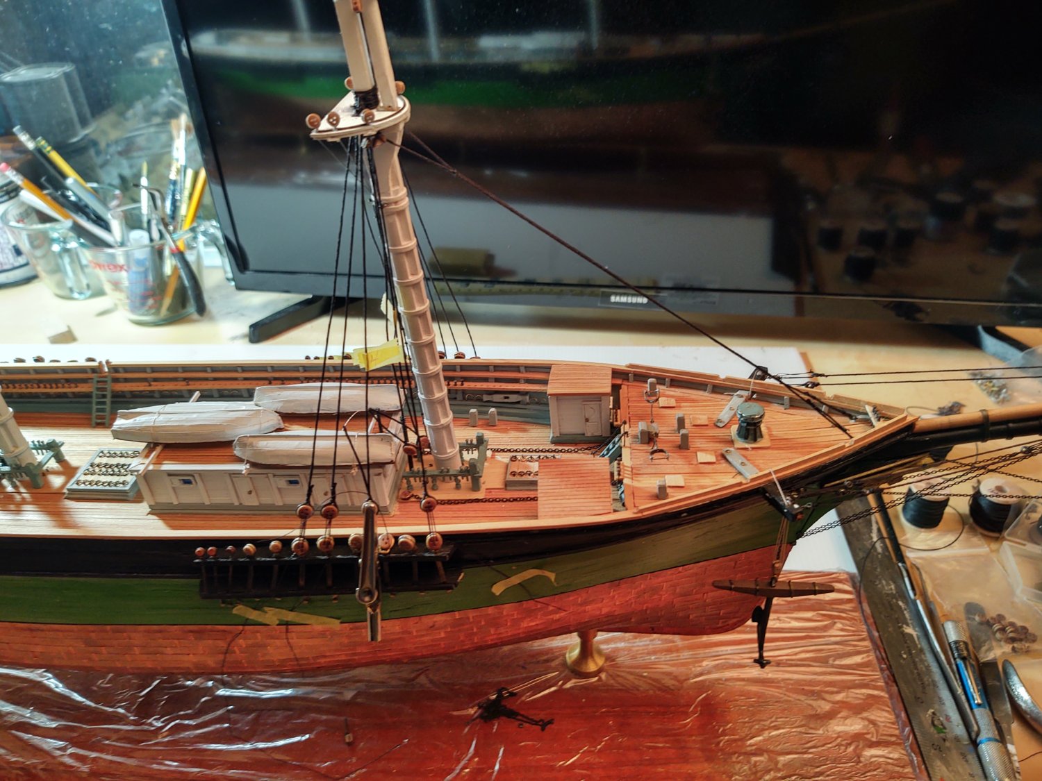
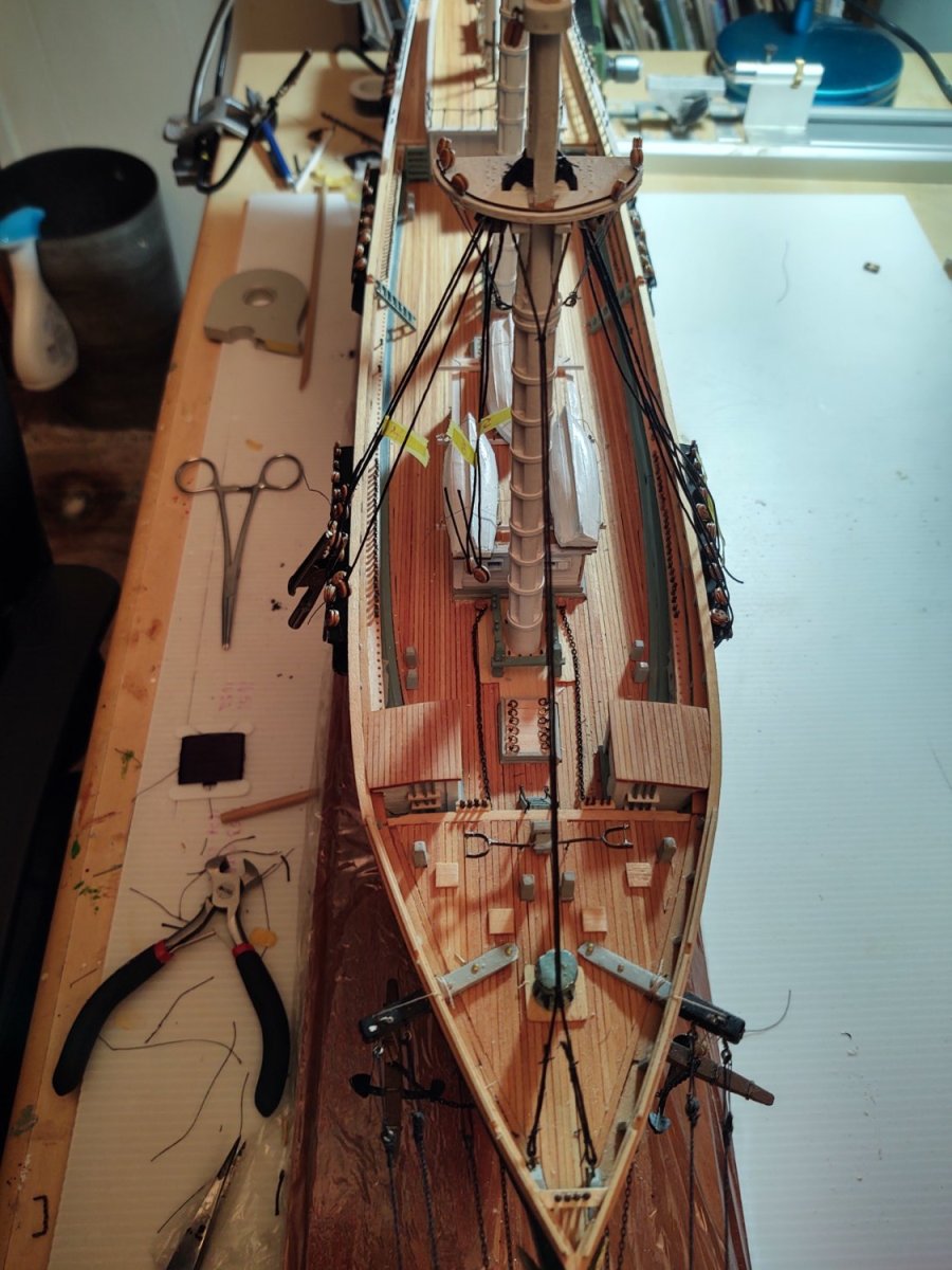
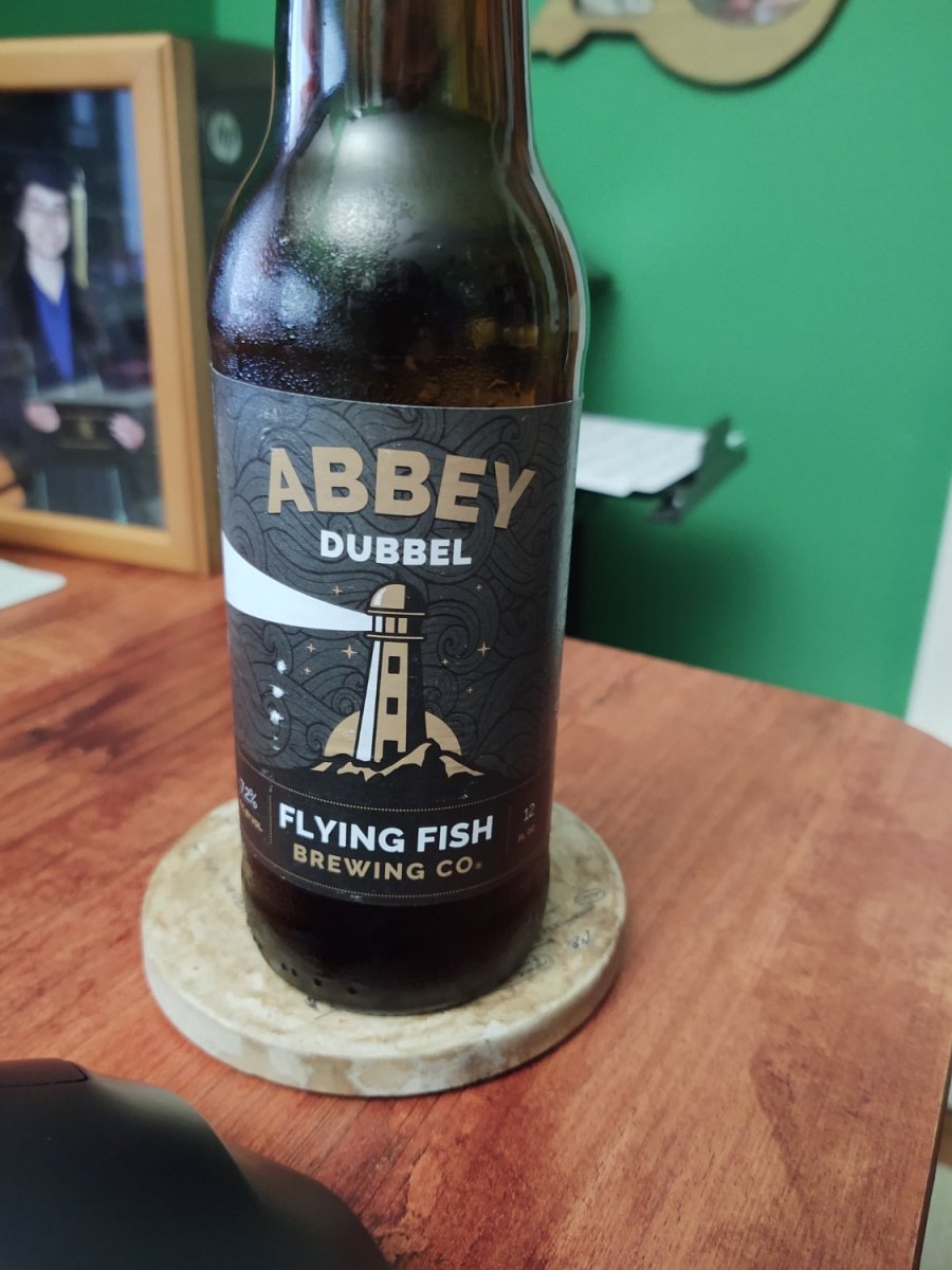
One quick update before I go into a hiatus of about 3 weeks. My wife and I are going to spend the next 2 weeks in Flagstaff, AZ. It's not a vacation - as we both work (mostly) remotely, and we're going to continue to do so, but we'll have two weekends to hike in Grand Canyon after the crowds have left for the season, and after I get back I am heading down to Wilmington, NC the following weekend for a triathlon. That means that the ship will be back home with no one working on it. So, current status: The shrouds on the foremast and the forestay have been installed: I started getting the shrouds ready on the starboard side, attaching the deadeyes using the traditional twisted wire spacer and seizing them in place. The yellow tape just indicates which shroud is which (1,2,3,4,...). Finally, two pics of the starboard shrouds with the deadeyes and (black) lanyards. The lanyards aren't tied down yet - I want to tighten P/S pairs of shrouds forward to aft, so I need to get the port side set up before I do anything more. Finally, in honor of the ship - tonight's beverage: I should be posting again in the third week of October, at which point I will be rapidly coming up on two years working on this project. For some reason I was thinking that I would manage this in two years (that's how long Niagara took), but this is a much more complex project - I expect another 6-12 months to go. As always, thanks for looking in and for the encouragement. Have a great end of September and early October! Regards, George K


- 602 replies
-
- 7
-
-
- Flying Fish
- Model Shipways
- (and 2 more)
-
@TAGood827 Assuming you mean the Revell Constitution there are 7 build logs that are tagged as 'Finished' and many others at different stages. You can find them in the indices for kit logs from 1750-1800 available here: https://modelshipworld.com/applications/core/interface/file/attachment.php?id=840412&key=a9d02329559034405c24d1cc0f3af501 And if you start a log, a lot of us have built this over the years and can provide answers to questions. One of the nicest things about being on this site. George K
- 481 replies
-
- 1
-

-
- Cutty Sark
- Revell
- (and 2 more)
-
Thanks guys. To be honest, it came to me after looking at Rob's gin block manufacturing process - it got me thinking a bit outside the box of 'make an exact miniature replica'. There are people that have that level of skill on here, but I'm not one of them. I've put the mounted the lower shrouds on the foremast and placed the lower forestay, but none of them are yet attached to deadeyes nor are any of the (black not tan) lanyards in place. More when it is further along.
-
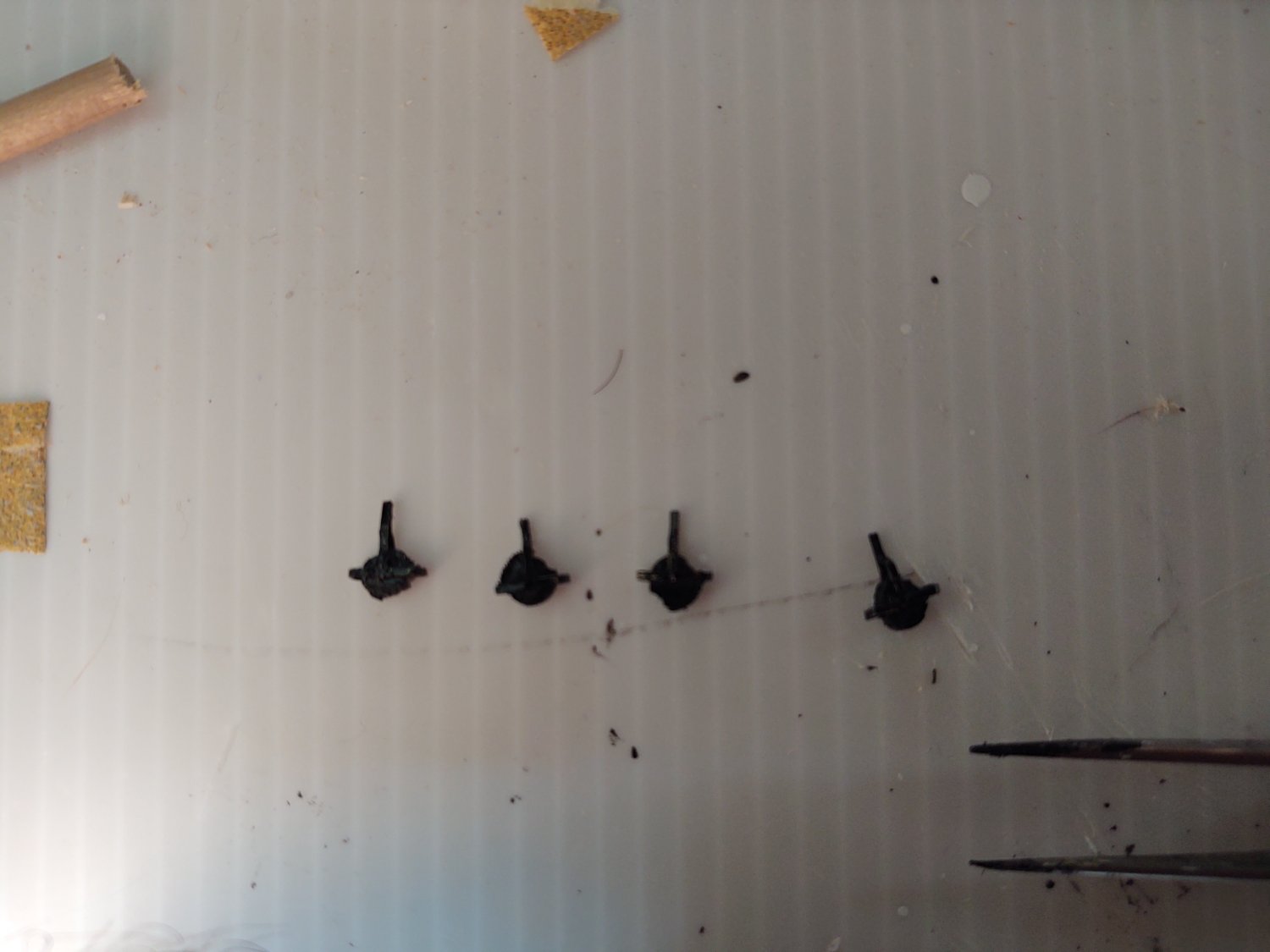
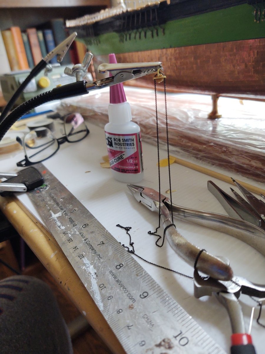
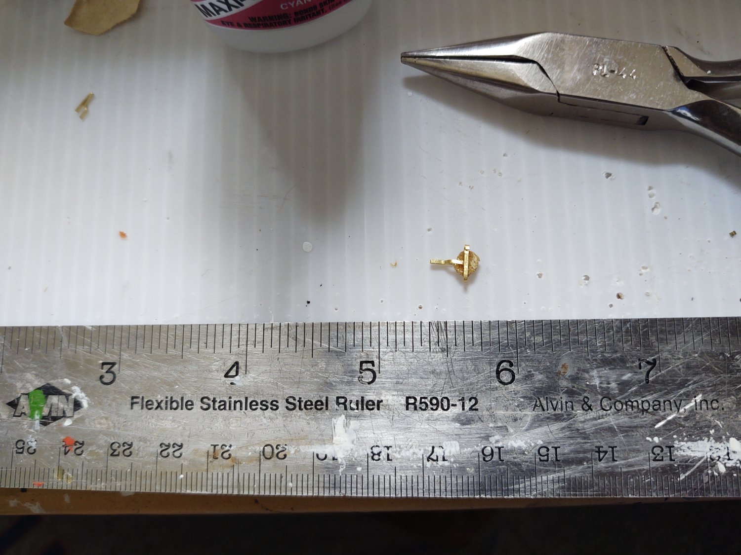
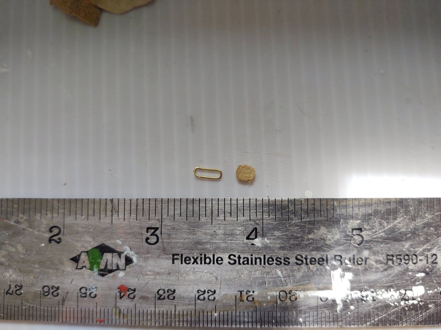
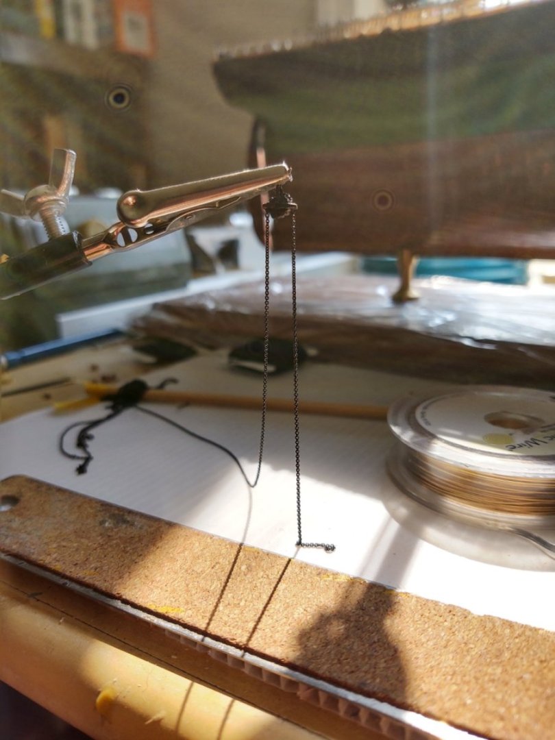
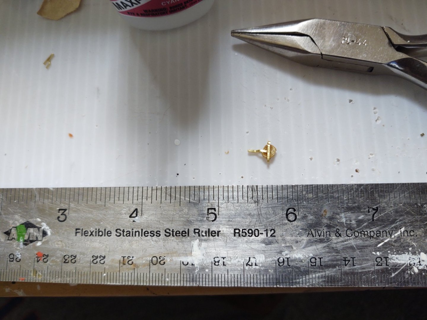
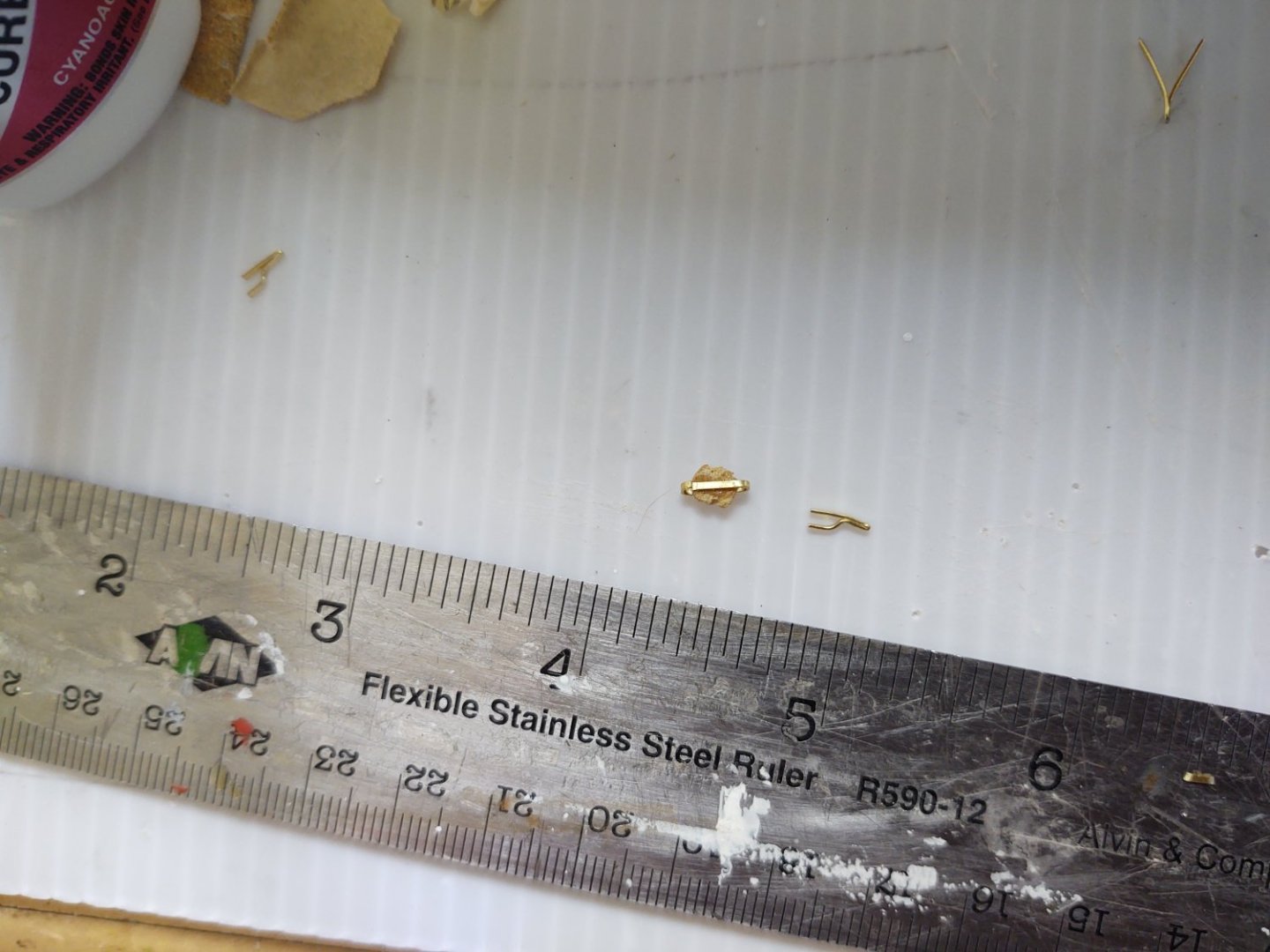
Well, I resolved how to manufacture the gin blocks (or whatever they are) used to haul the halliards. My eureka moment was to realize that it didn't matter if the pulley actually turned, the chain would slide along more or less regardless with a little bit of space. So I cut a thin slice out of a 1/8" dowel, and made a small rectangular box out of 1/32" wide brass strip as below: I glued the disc inside the brass box, and fabricated a piece with a hanger and two open ends (like a tuning fork): That was then glued onto the block to make the completed block: The chain runs through the block and can move to be positioned even though the pulley is stationary: So, I made four of them, painted black (the blocks are iron). This is one of the completed blocks with chain: So, anyways, the foremast now has all of the mast mounted blocks and is firmly mounted and ready to start putting in shrouds and stays. I have a couple of items to install on the main, and will then mount it as well. The gin blocks on the mizzen are smaller, so they still need to be manufactured before I can fully mount the mizzen. As always, thanks for looking in! Regards, George K


- 602 replies
-
- 7
-
-

-
- Flying Fish
- Model Shipways
- (and 2 more)
-
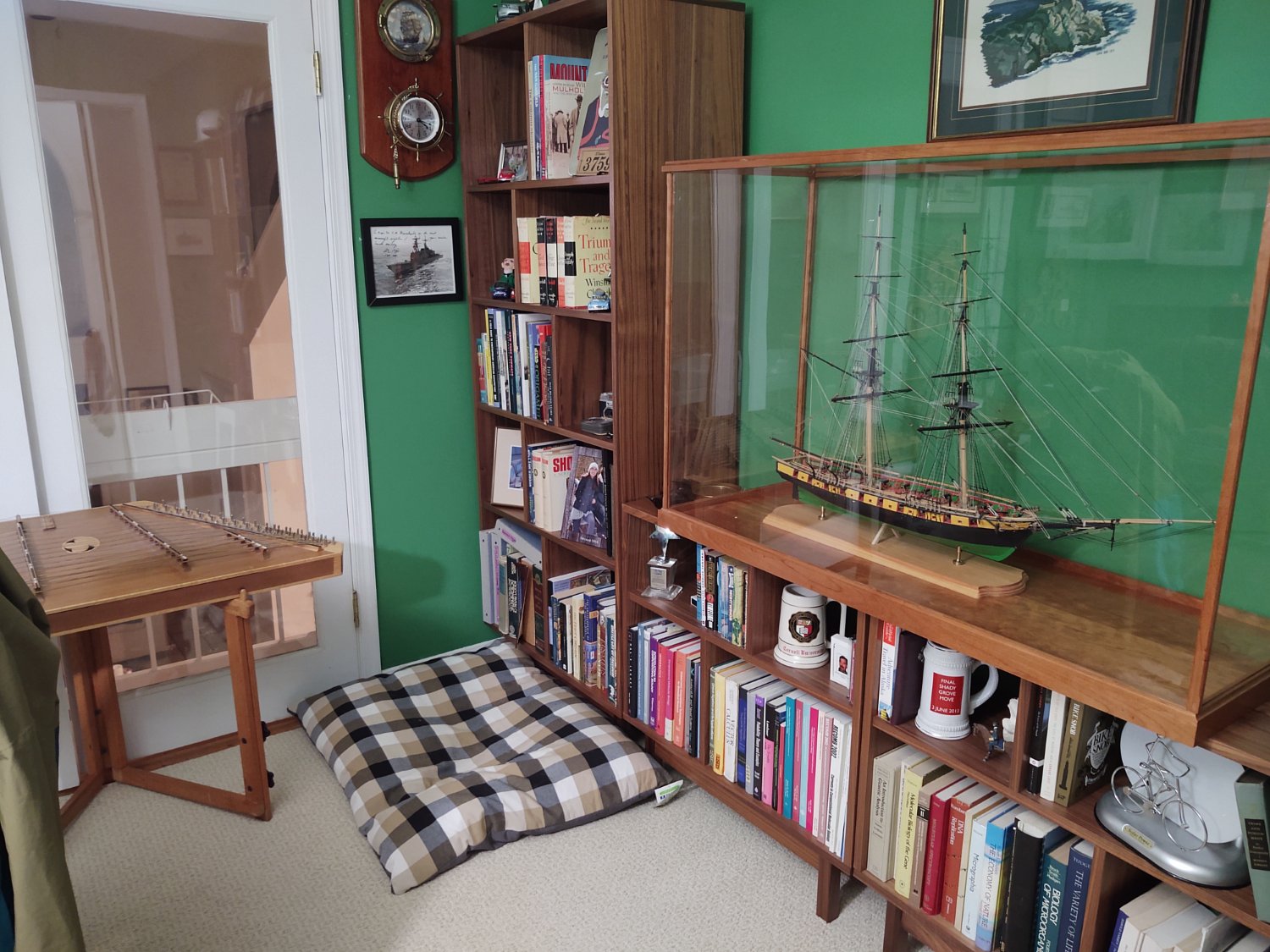
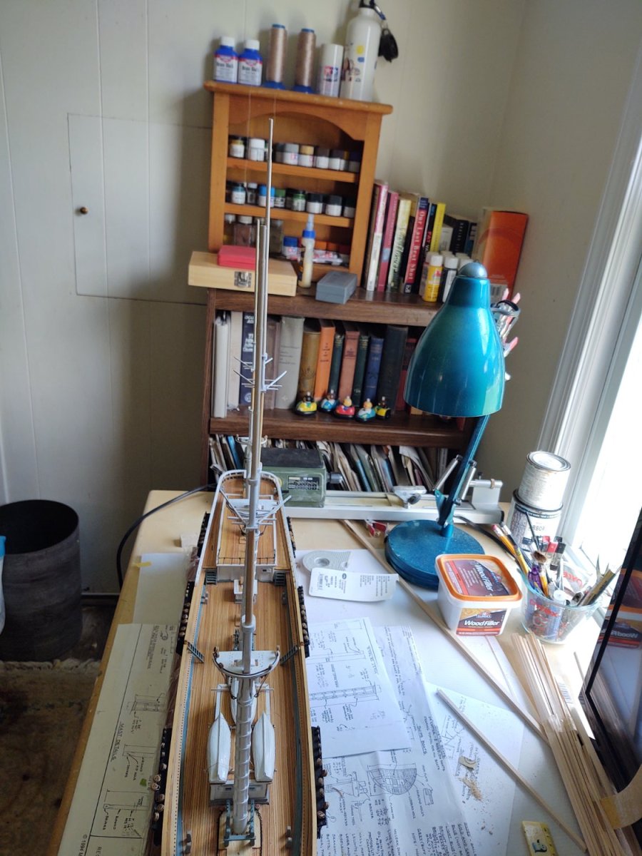
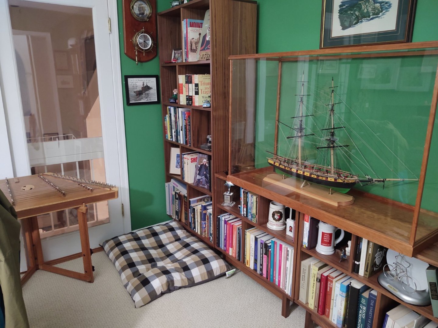
@Cathead, do you play the hammered dulcimer. I think I see one in the background there, a certain similarity to my home office.
- 113 replies
-
- 7
-
-
- Cairo
- BlueJacket Shipcrafters
- (and 1 more)
-
That is alarming. Glad to hear you are recovering and going to follow along.
- 113 replies
-
- 5
-
-
- Cairo
- BlueJacket Shipcrafters
- (and 1 more)
-
Thanks! I am always on the lookout for your next post!
-
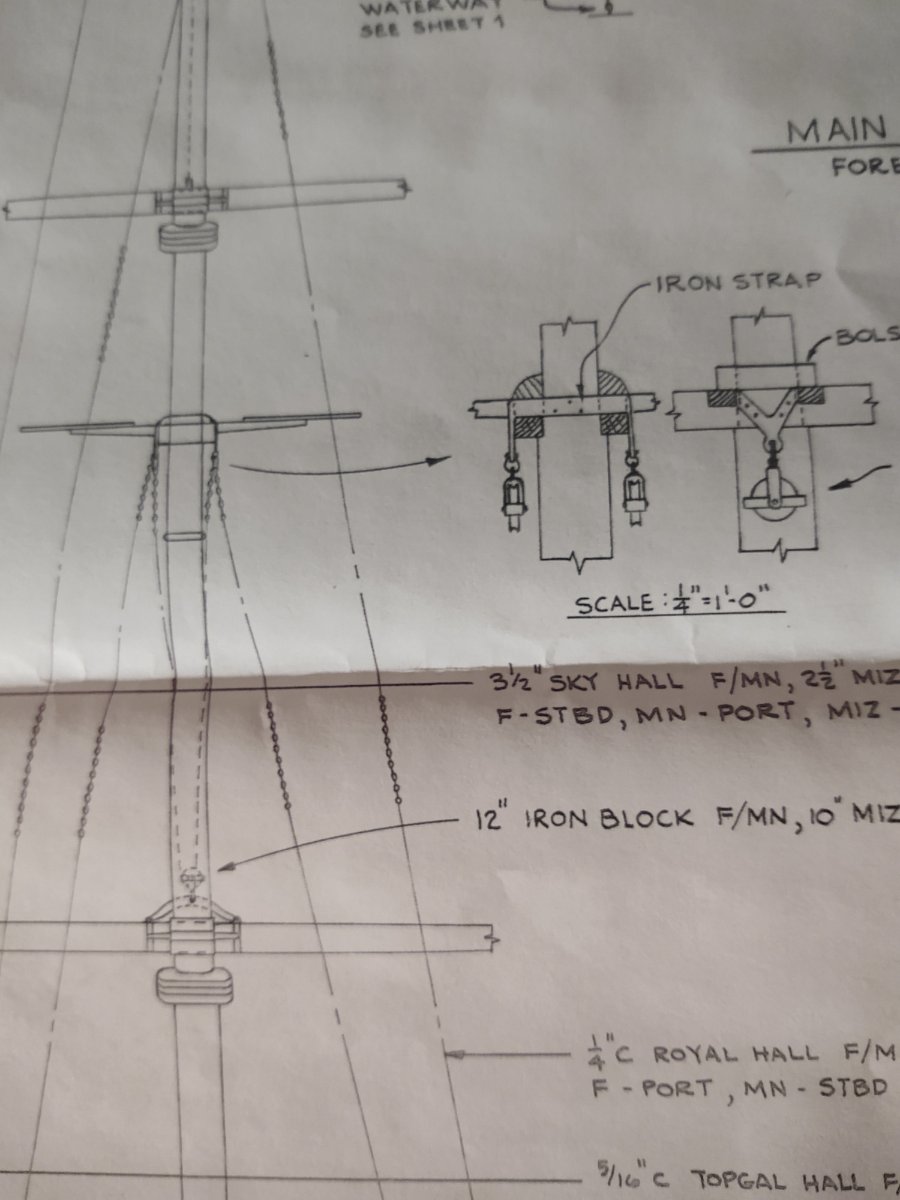
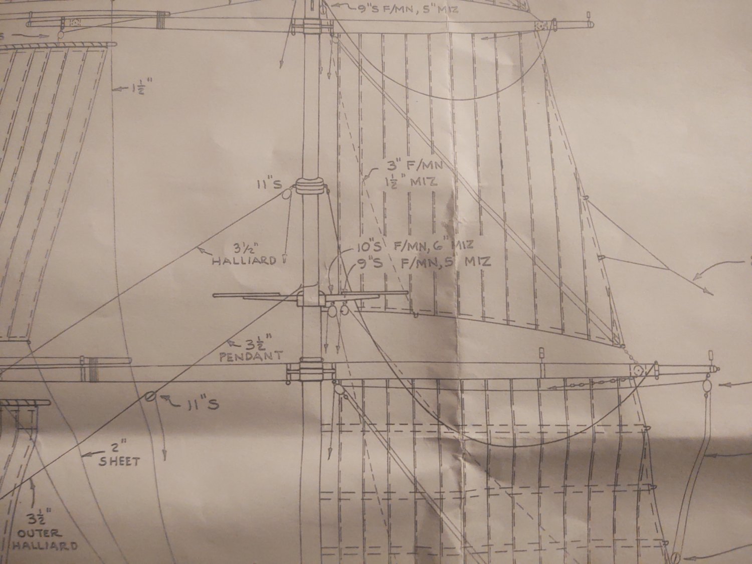
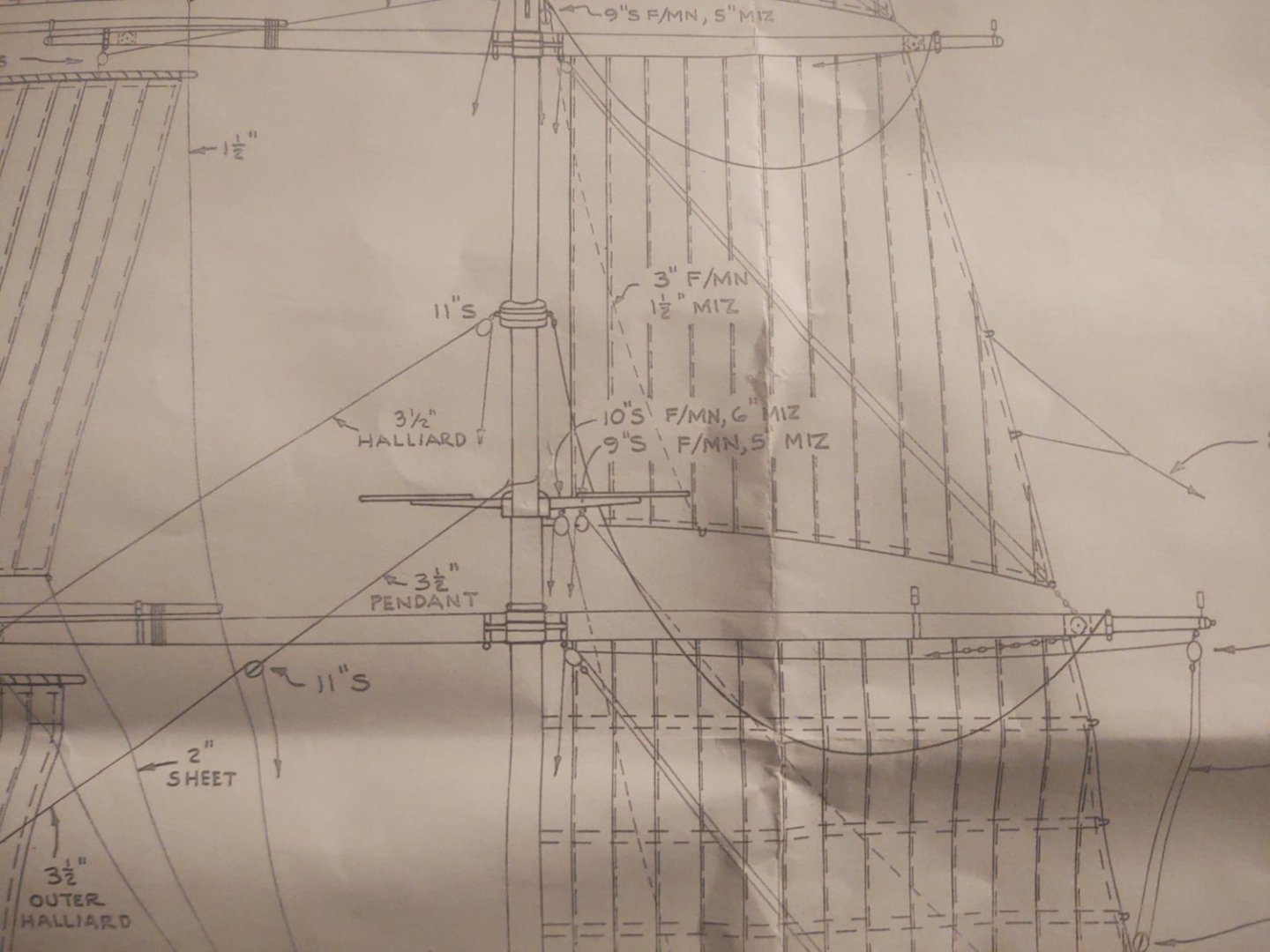
They might be - and that is in fact an ingenious fabrication method. So it is a set of blocks for hauling the topsails. The rest of the halliards are just as you describe, sheaves directly in the mast and I'm just using holes for those rather than try to install the actual sheave. This is a more complicated rig just for the topsail. I'm including a snap of a small section of the plans that show what I'm talking about: They do look like gin blocks but mounted as a pair on the trestle trees instead of on the yard. Regards, George K

-
Well, bowsprit rigged until it is time to mount the forestays (soon!). A couple of pics: The foremast needs 4 more blocks before it's time to start mounting shrouds. One question I hoped that someone like @rwiederrich might be able to answer is how they handled the halliard blocks on the trestle trees (given that those are 2 of the four). The plans suggest that they weren't standard wooden blocks, but something that frankly looks more like a sheave (or maybe a roller on a desk chair), an iron circle inside of a triangular support. So far, my attempts to fabricate them have failed utterly or just been badly out of scale. I could paint standard blocks black so that they are more like iron, or if anyone has suggestions, I'd love to hear them. Thanks for looking in! George K

- 602 replies
-
- 4
-
-
- Flying Fish
- Model Shipways
- (and 2 more)
-
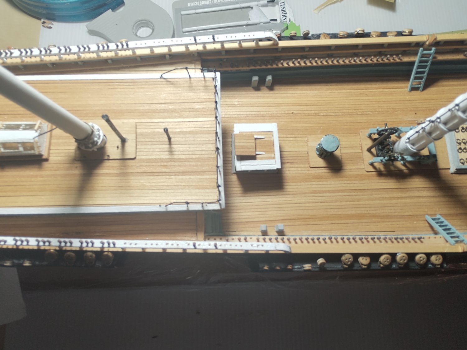
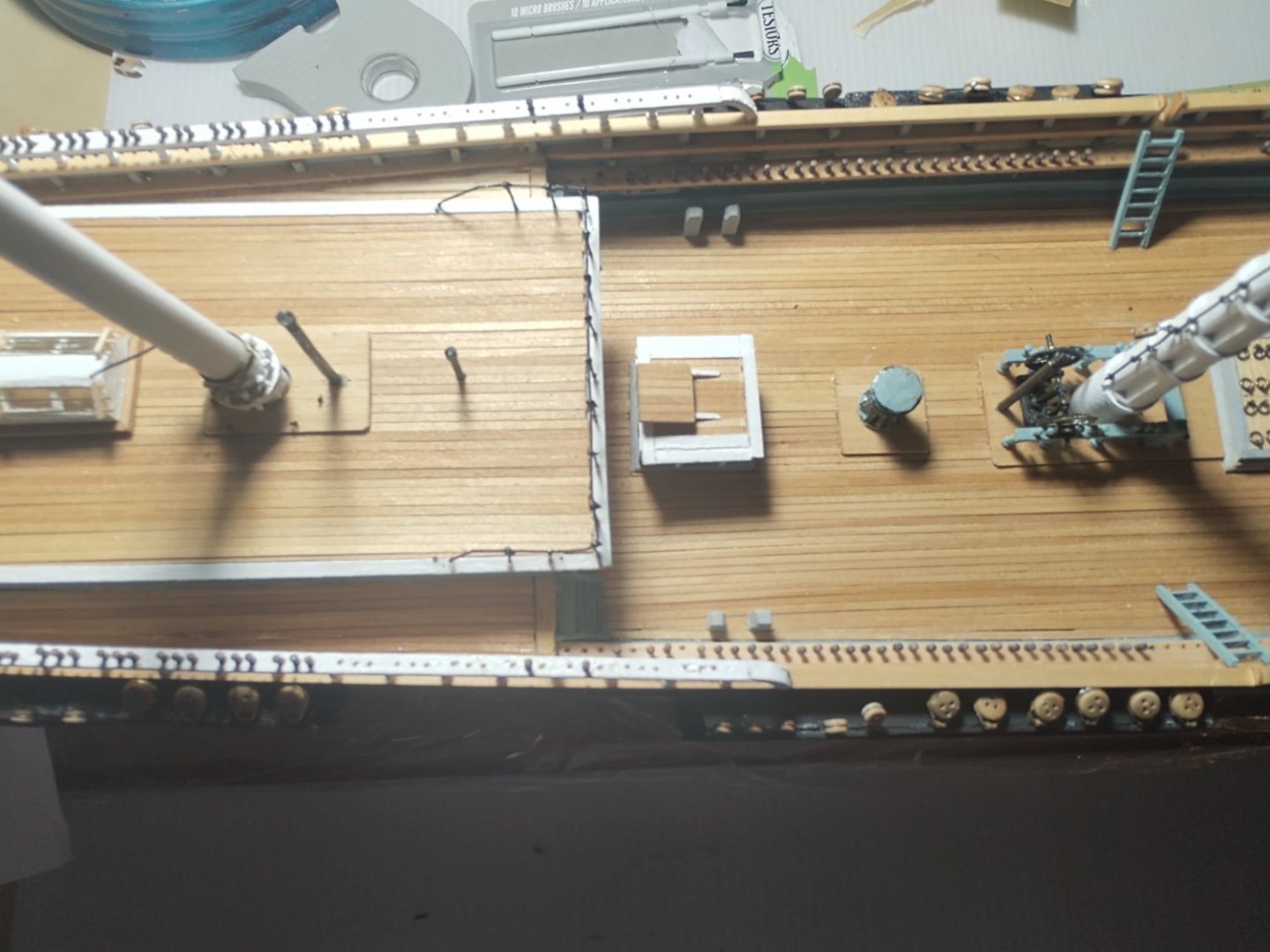
Sorry - I think we are actually saying the same thing, I just did so poorly. Both the supplied plans and the description point to the mounting points being topside of the main deck and below the forecastle deck in the open forecastle interior to the bulwarks. Here is a small section of the plans to show you what I mean: My problem is that there is deck covering the space where the lines would belay, and it would involve drilling through both the bulwarks and the ceiling planks to get there. Probably not impossible with sufficient patience and some specialized tools, but I'd need a (very small) offset drill with a very short bit (something like a dentists drill) to put in the necessary holes for the belaying bolts. So, anyone that wants to do this maximally accurately will need to put in the belaying points (and I'd recommend drilling the hole in the bulwarks) before they plank over the forecastle. And because of the amount of strain on the lines, I'm not really hip about trusting to glue to hold the lines in place (which is what the instructions suggest). So, likely a bolt in the bulwarks. Regards, George K
-
Brian, Appreciate the insight. I think it's a perfectly fine way to manage lines that go into inaccessible locations. The sheets probably didn't have a huge amount of stress on them, but I don't have a good feel for the amount of strain on the forestays of the Academy model. Are the deadeyes/lanyards one plastic piece or are they held together with thread? If the latter it would tend to suggest that the glued line/bulwark joint can take a fair amount of strain, which is the question here. Rick, That's my concern too. I'm worried about the amount of stress on the stays. The doubled lower forestay anchors in the knightheads, but the doubled topmast forestay that goes through the bees to the bulwarks has the combination of a decent lever arm, a stiff spar, and plenty of pull from the backstays that makes me think it's going to need to be pretty strongly seated. I suspect I'm going to take the approach of mounting a homemade eyebolt (that will have the twisted wire stem for better grip) with some CA glue and belay the lines on the bolt. Maybe bend the stem so that it can adhere to the bulwark from behind, or if I'm lucky have it screwed into one of the bulkheads. Not technically correct, but I'll keep the loop just big enough for the line and a black eyebolt against a black bulwark with black line will hide the sins.
- 602 replies
-
- 1
-
-
- Flying Fish
- Model Shipways
- (and 2 more)
-
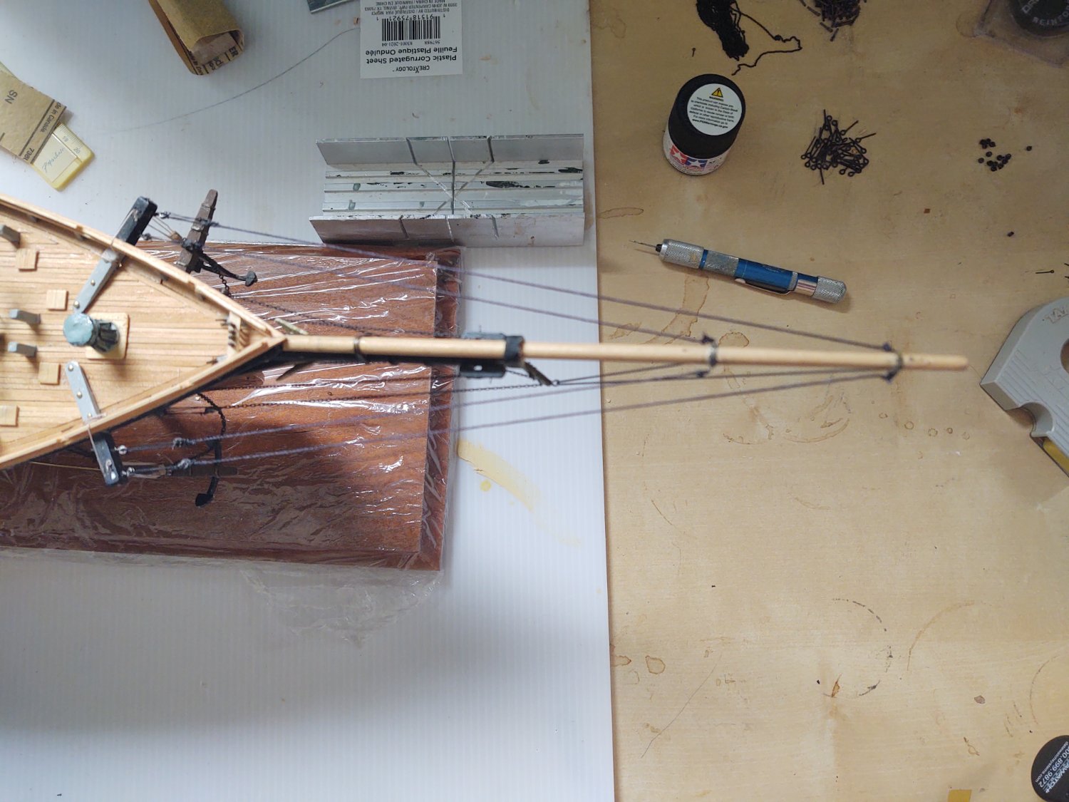
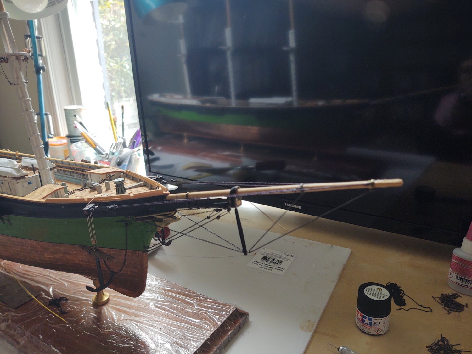
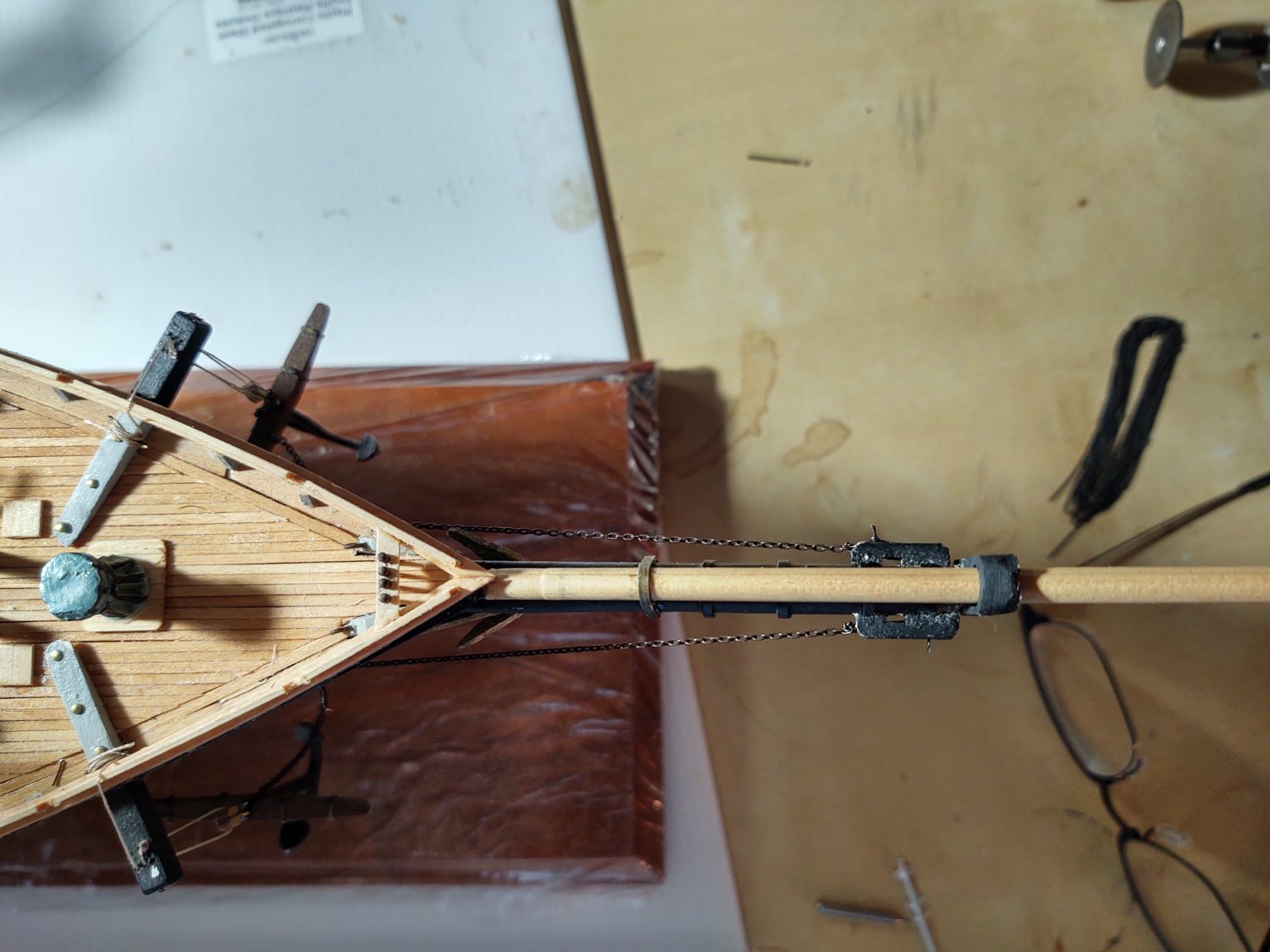
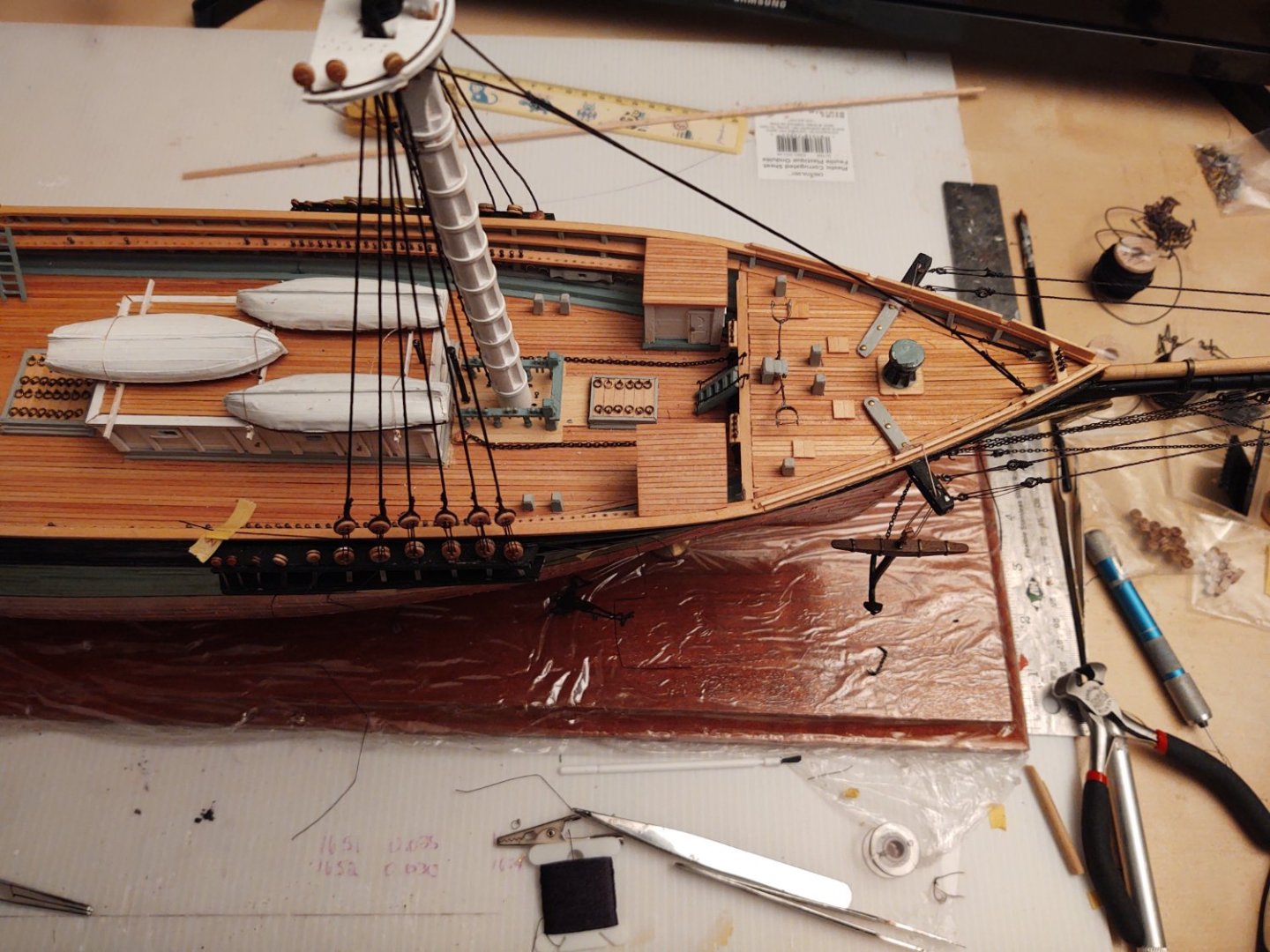
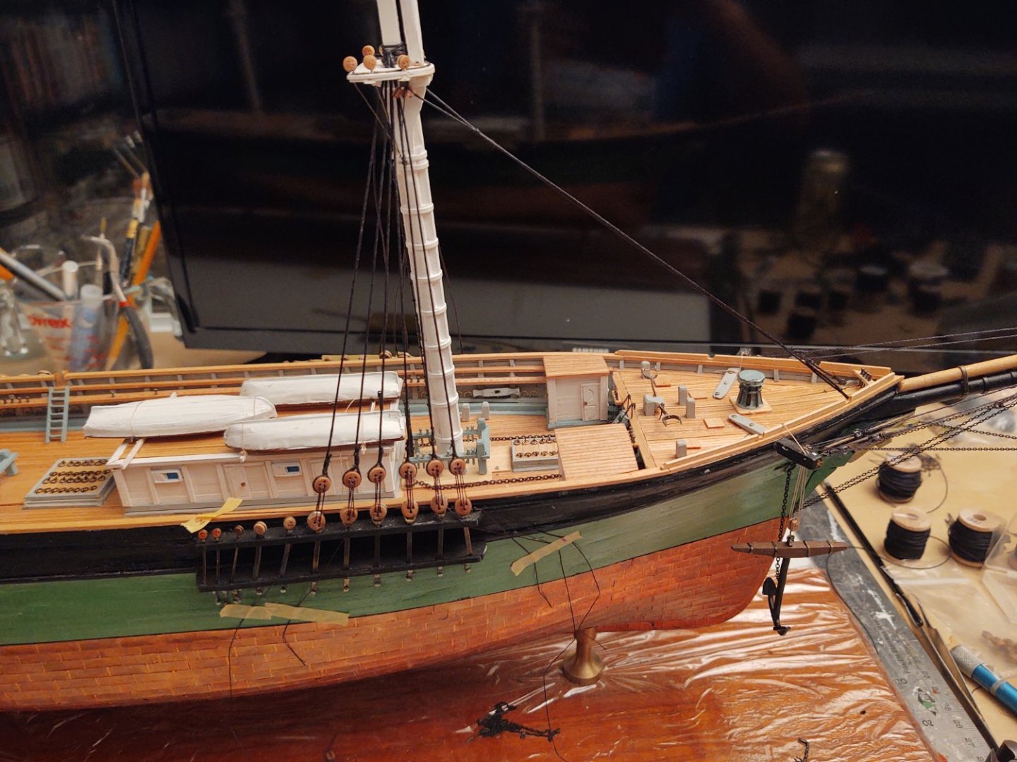
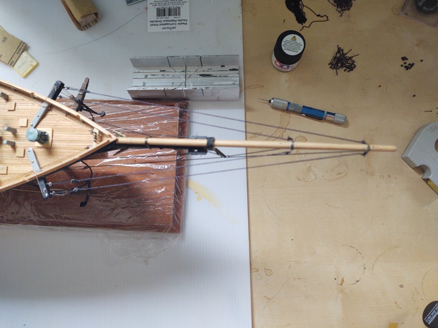
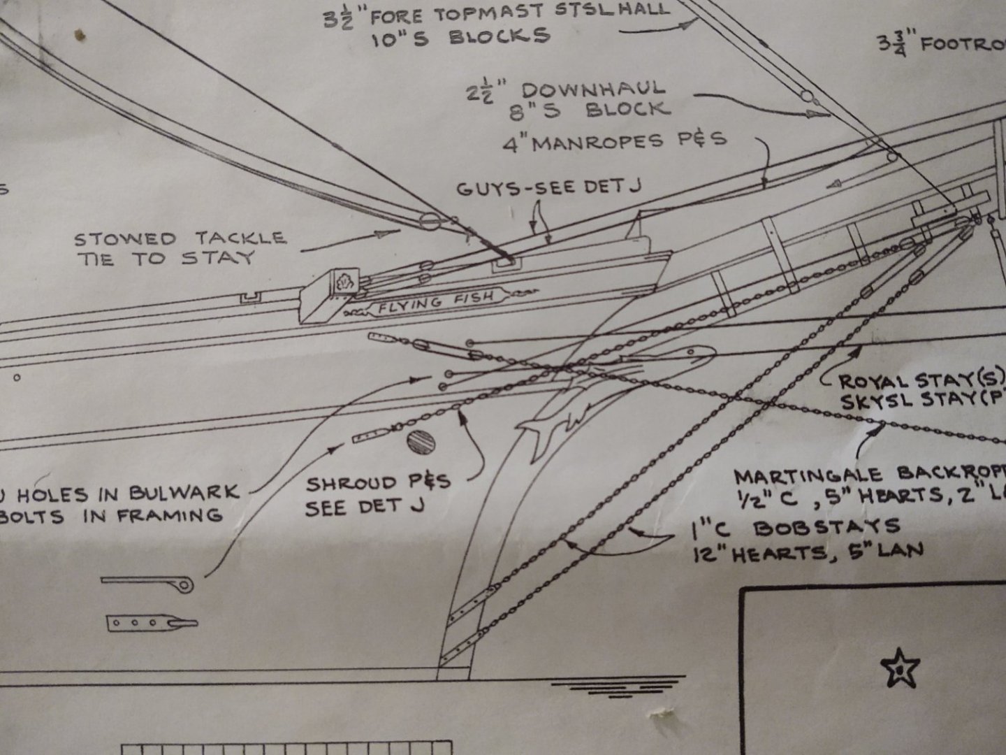
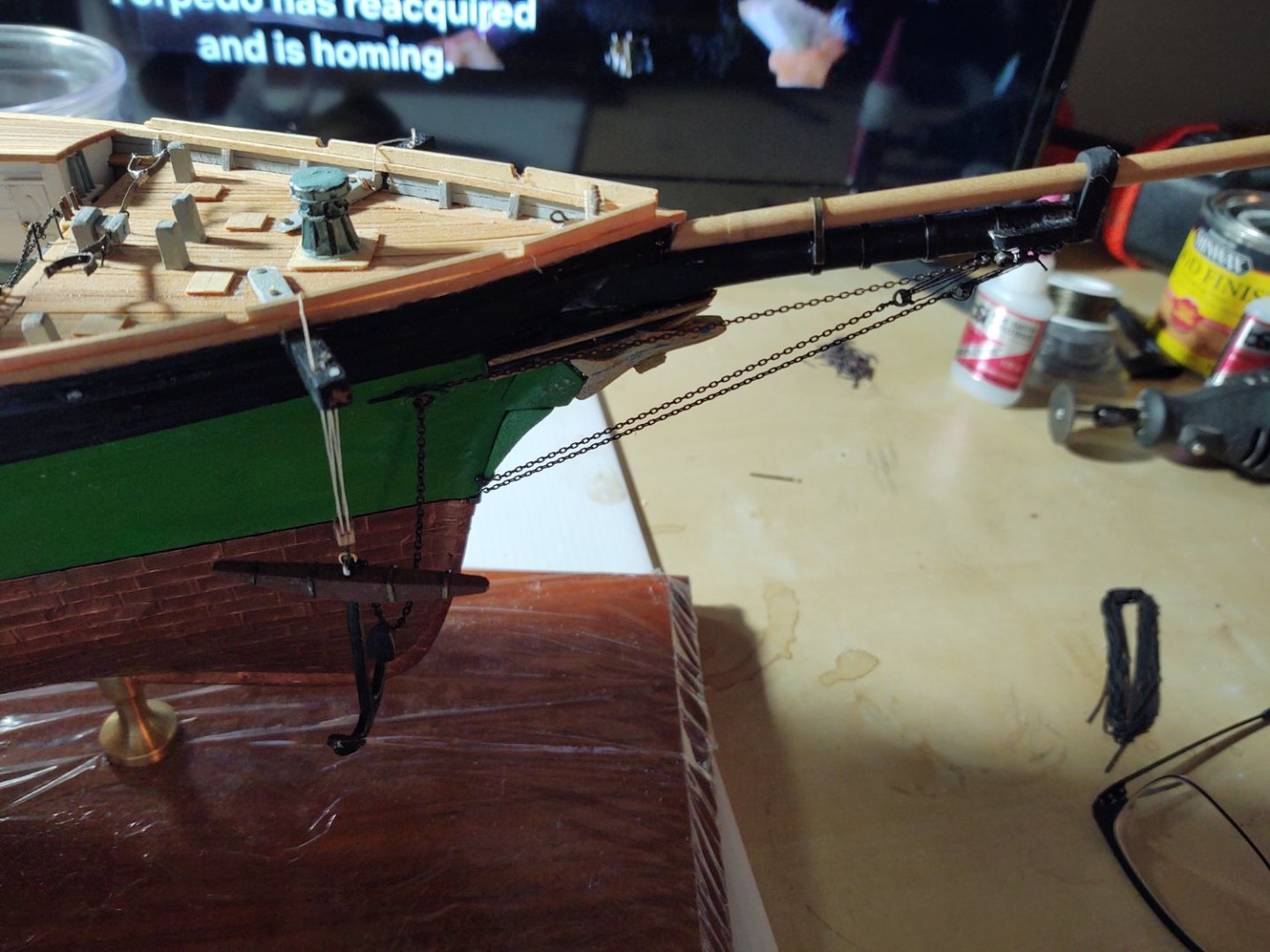
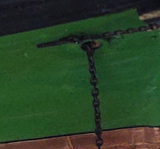
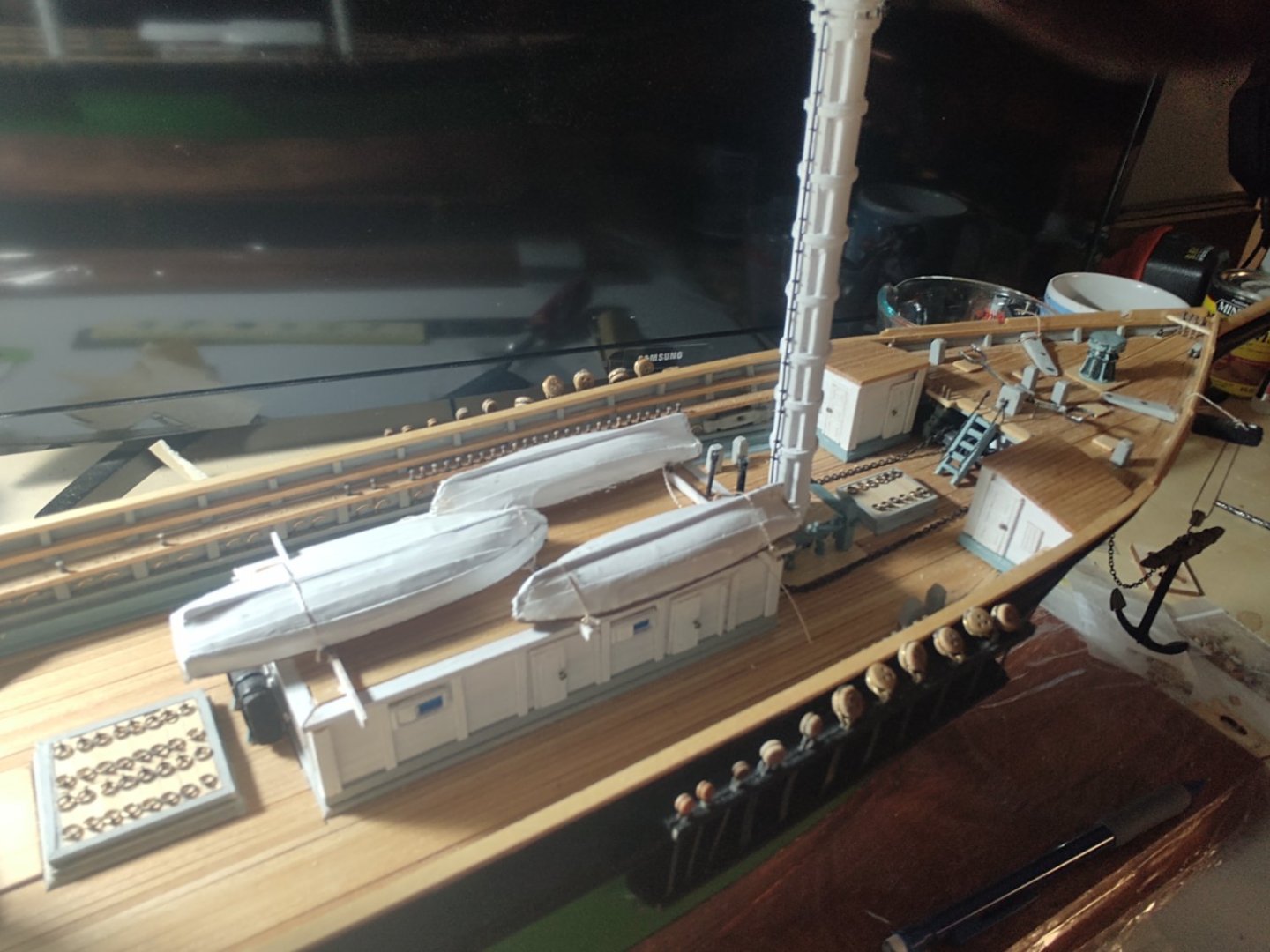
Well, another milestone reached. I'm still mounting blocks on the masts (but I think I'm almost done with that), so to break up the routine I started rigging the bowsprit. So far, I've only installed the bobstays and the shrouds. The kit surprisingly did not include any hearts (although there was a laser cut sheet that included what I thought were mast hoops that turned out were bullseyes). In any case, I bought some extras from Bluejacket and used them. The kit had a single diameter of chain for everything. When I put the anchors together, I thought that the supplied chain was massively out of scale (too small), so I bought a couple of feet of two larger sizes, the intermediate of which I used to represent the 1 inch chains on the shrouds and bobstays. For the bobstays, I stropped the hearts with 34 gauge black wire and then bent the tail into a hook which I either inserted into a jackstay eyebolt (for the non -chain end) or the chain itself. The lanyards are black seeing as this is standing rigging. Here is a view of the stem and bowsprit. Here is a view showing the shrouds. The forward attachment of the shrouds is pretty much the same as the bobstays, but the hull end is quite different. The bobstays are basically attached to an eyebolt embedded in a metal strap. By contrast the shrouds are attached as in the photo below (sorry about the image quality). The mounting strap is 1/64" wide brass, with a split ring attached on one end, and the chain attached to the split ring (anchor chain obviously coming from the hawse pipe). From the last post, no one had any suggestions, so I wound up mounting the blocks on the forward cross tree - it makes sense from logic and the similar blocks on the mast tops, so, that's how I decided to proceed. Next step on the bowsprit is to rig the dolphin striker and the associated martingales and bobstays. The kit comes with a Britannia striker, but I think I'm going to scratch build one. It's the correct length but the locations for the stays are all wrong, and it's just a bit clunky. One decision that I will need to make eventually is how to terminate the various stays on the foremast on the hull. The Boston Daily Atlas indicates that the stays were belayed inside the ship on various frames, which is to say under the forecastle which is pretty much inaccessible at this point. Doing this in the way of the real ship would seem to require drilling through both the hull planks and the ceiling planks, feeding the line through both and terminating them somehow inside the ship. Two options come to mind, one of which is to drill holes in the outer hull, feed the line in and glue or to mount to small eyebolts. Neither is perfect, I suspect that I will do the latter as the lesser of two evils. If I had thought further ahead, I might have run the lines before I decked over the forecastle, but we can all be wise in hindsight. As always, thanks for looking in! Regards, George K. PS - Background movie in the first pic is, of course, The Hunt for Red October. One of several proper choices, I think you will all agree, for ship modeling.

- 602 replies
-
- 4
-
-
- Flying Fish
- Model Shipways
- (and 2 more)
-
A bit off topic, but if you read the Wikipedia article on the bridge it is astonishing how many people seem willing to damage a historic bridge (and possibly fall to their deaths) to avoid following clear instructions. Good grief.
-
For the Lakers out there, the Article of the Day on Wikipedia is the Edward L. Ryerson! https://en.m.wikipedia.org/wiki/SS_Edward_L._Ryerson Regards, George K
-
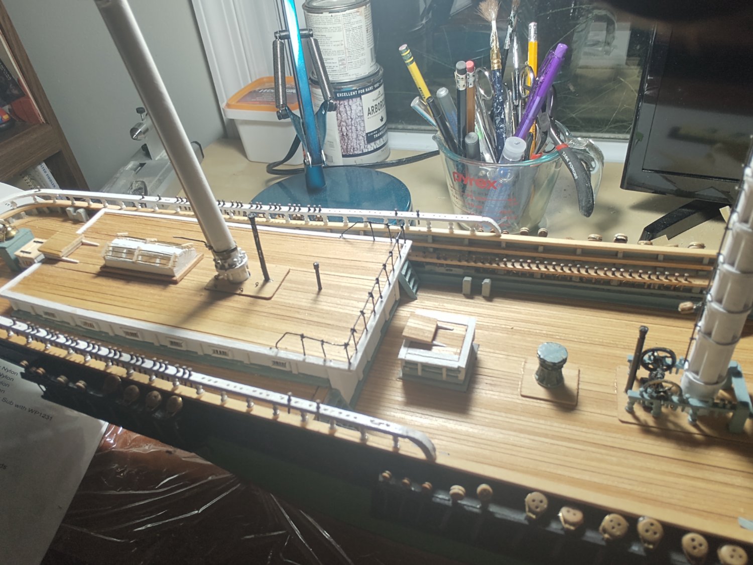
Hello all, A brief update and a question to the clipper cognoscenti. I've been mostly stropping and mounting blocks on the masts so they will be there when they are need during the rigging process. The one major change is that I've mounted all of the belaying pins, which were first chemically blackened per a suggestion a couple of months ago. There are a lot of pins! A couple of photos: On to the question. There are blocks on the mast tops and the trestle trees that are for the bunt and leech lines. I've included a pic from the plans that show the blocks on the topmast cross trees. The plans plus the instructions indicate that the blocks on the tops go on the forward cross tree. I can't definitively determine the situation on the topmast. Logic says put them on the forward cross tree, but if anyone has thoughts otherwise, I would love to be enlightened. As always, thanks for looking in! George K

- 602 replies
-
- 4
-
-
- Flying Fish
- Model Shipways
- (and 2 more)
-
Spritsail yards on Niagara and Constitution
gak1965 replied to gak1965's topic in Masting, rigging and sails
That makes sense. It's certainly true that on the Niagara the jibboom stays are routed onto the spritsail yard. So the spritsail yard lifts and braces basically become 'standing' rigging to anchor the yard in 3 dimensions since it's basically just lashed onto the bowsprit? -
Dumb question that I haven't found an obvious answer to using simple searches. Why did Niagara and Constitution (and I presume other ships) have spritsail yards that did not have sails bent? I understand the physical reason why they didn't have a sail due to being blocked by the dolphin striker, martingales, etc. But why wasn't the yard itself eliminated with the sail? It must have served some purpose or, as Long Jack would say, "twould be overboard", although certainly by the time the clippers came along they were gone. Thanks, George K
-
Bob, Looking great! Having not seen the Harriet Lane plans, do they use this "heavier" or "thinner" language or is it only in the instructions? My experience with 3 MSW kits is that they mark line diameter or circumference for the real ship on the plans and then you need to convert to the available line. I've never seen an MSW kit with all the different scale lines (or deadeyes, or hearts, or whatever) shown on the plans, they generally provide some number of sizes and you match as best you can or obtain additional material (I have giant spools of rigging thread now). Regardless, I wouldn't lose any sleep over the exact line thickness. Lines got replaced when worn out, maybe you could find the same size, maybe not. Real ships were always a mixed bag. And thinner at least tells you to relative size WRT the footropes, I tend to use standard black sewing thread. I'm sure others do differently. The one thing that I found helpful is to make the stirrups from wire. Much easier to deal with and they hang better in my opinion. Regards, George K
- 146 replies
-
- 1
-
-
- Harriet Lane
- Model Shipways
- (and 1 more)
-
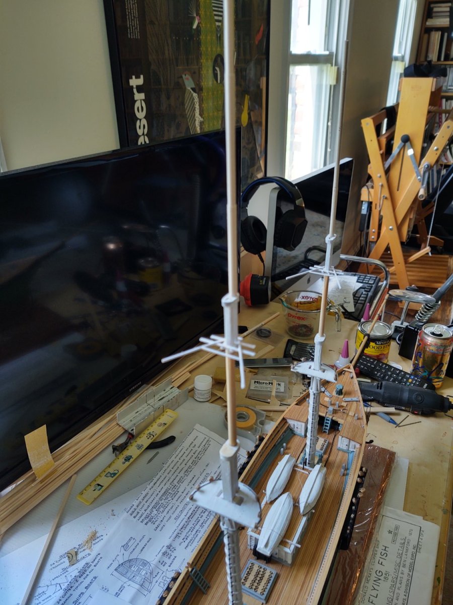
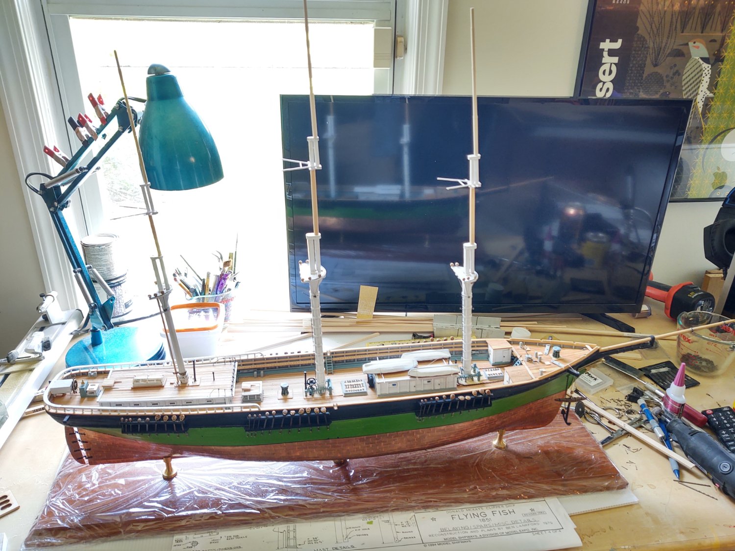
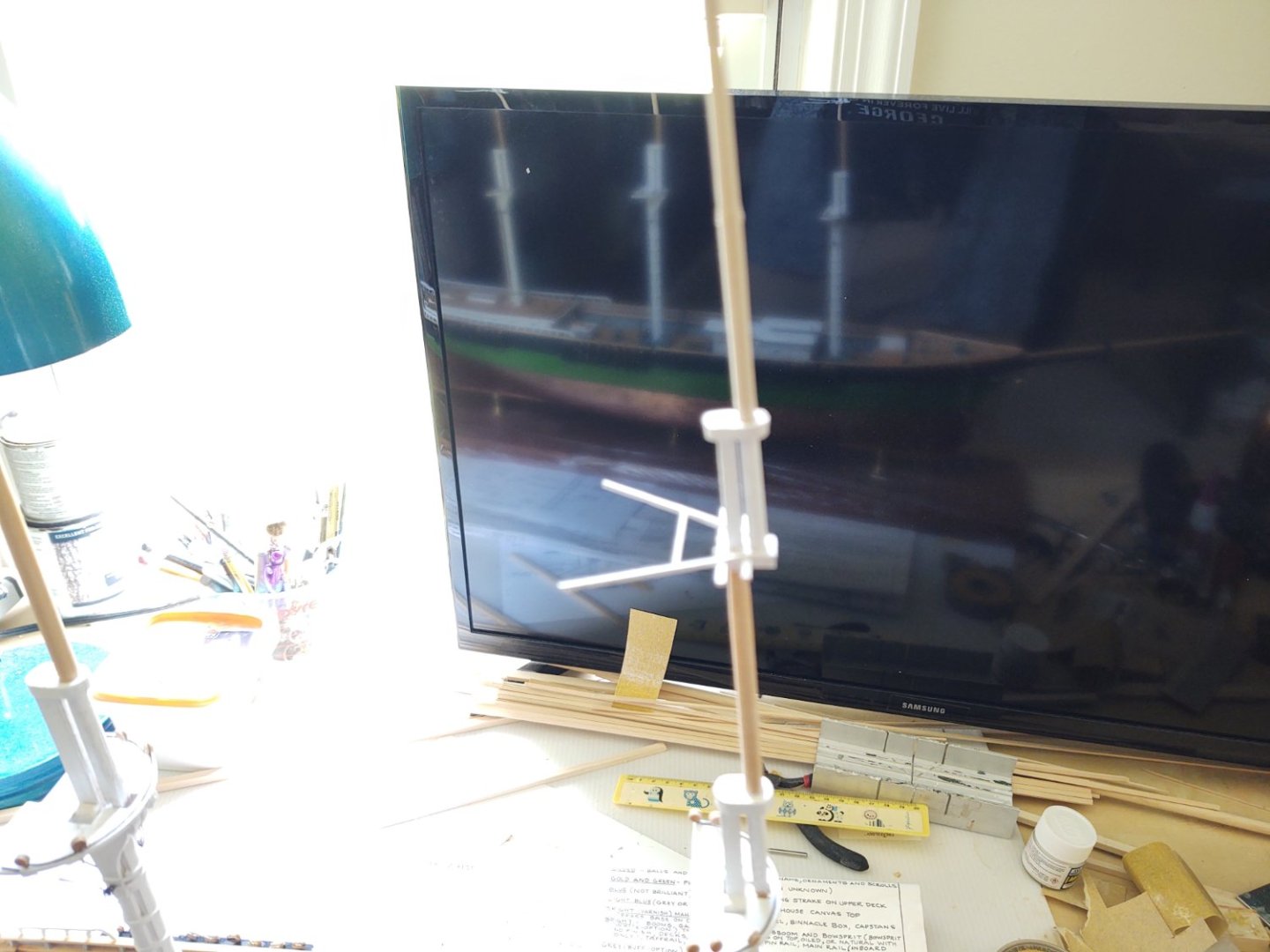
Well - away from 20th century vessels and back to the 19th. I've completed all three topgallant masts, and assembled them into the fore, main, and mizzen. The doublers are all painted white, with everything else "bright". At some point, I will need to add the gilded balls and (I presume) lightning rods, but I think that can wait until the ship is almost done. A couple of photos. The fore and main in situ as it were: and all three looking to port, and from the stem: And, kind of an odd view looking diagonally forward. A couple of observations. First, the fore topgallant mast seems to be raked a bit more than I want - I think the spar itself has a bit of a bend. When I put the forestays on I'll move the tip forward maybe 4-5 mm and it will align with everything else. What I am happy about is that there are no obvious problems with the alignment of the masts port and starboard (see the pic from the stem). Second, this was definitely a learning exercise. Even though the birch dowels I used to make the topgallants were denser and stronger than basswood, at this thickness and length there was no way to use my cutting tools without either (a) the spar just bending away from the tool or (b) snapping in two. Even after this discovery, it took 3 tries to do the first, 2 tries for the second, and fortunately only 1 try for the mizzen topgallant mast. Speed is not your friend - if I used sandpaper that was too rough (say less than 100 grit) to "rough out" the shape, I always wound up having the thinnest part snap (even when I wasn't sanding in that region). Interestingly, what did seem to work well was to start at the narrow end (so that I made clear "ridges" where the diameter changed), using 150 grit and then sanding the other segments to make a spar that had the right proportions (i.e. it had 4 segments with specified length and proportionally smaller diameters) but was still too wide, and then go back with a mix of 150 and 220 grit to eventually obtain the proper diameters. For once, I didn't have to remake all of the mast caps. By gently hand sanding the openings wider I was eventually able to get the diameter of the holes sufficiently large to fit the spars. I did bust one of them, but it was less trouble than I expected to make a new one for some reason. In that case I hand drilled (i.e. I spun a 1/8 inch drill but with my fingers) to get the hold opened in a piece larger than the cap, and then sanded the rest of the opening. Anyway - next steps are to place the remainder of the mast mounted blocks (there are quite a few) and mount them on the ship. I've seen many people do wonderful work mounting the yards before they fully mount the mast - that hasn't been how I've done it in the past, and so for now the plan is to mount before rigging. One thing that has occurred to me is that I should probably make sure that I've drilled and fitted the path for the boat davits in the mizzen channels before I start putting in the shrouds. Drilling afterwards could be ugly. As always, thanks for looking in! Regards, George K


- 602 replies
-
- 4
-
-
- Flying Fish
- Model Shipways
- (and 2 more)