HOLIDAY DONATION DRIVE - SUPPORT MSW - DO YOUR PART TO KEEP THIS GREAT FORUM GOING! (Only 68 donations so far out of 49,000 members - Can we at least get 100? C'mon guys!)
×


gak1965
-
Posts
721 -
Joined
-
Last visited
Content Type
Profiles
Forums
Gallery
Events
Everything posted by gak1965
-
 Speedy recovery! I find the logging helps keep me moving along - so if you do build, might as well put some info down for the next person to come along. Regards, George K
- 481 replies
-
- 1
-

-
- Cutty Sark
- Revell
- (and 2 more)
-
USS Samuel B. Roberts found. Sunk during the Battle of Samar
gak1965 replied to mtaylor's topic in Nautical/Naval History
Wow. And the story suggests that they found the USS Johnston as well. There is a great book on the subject of the Battle off Samar, "The Last Stand of the Tin Can Sailors" by James D. Hornfischer. -
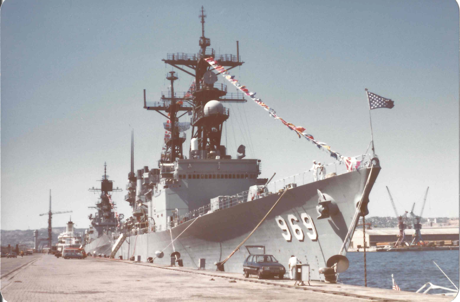
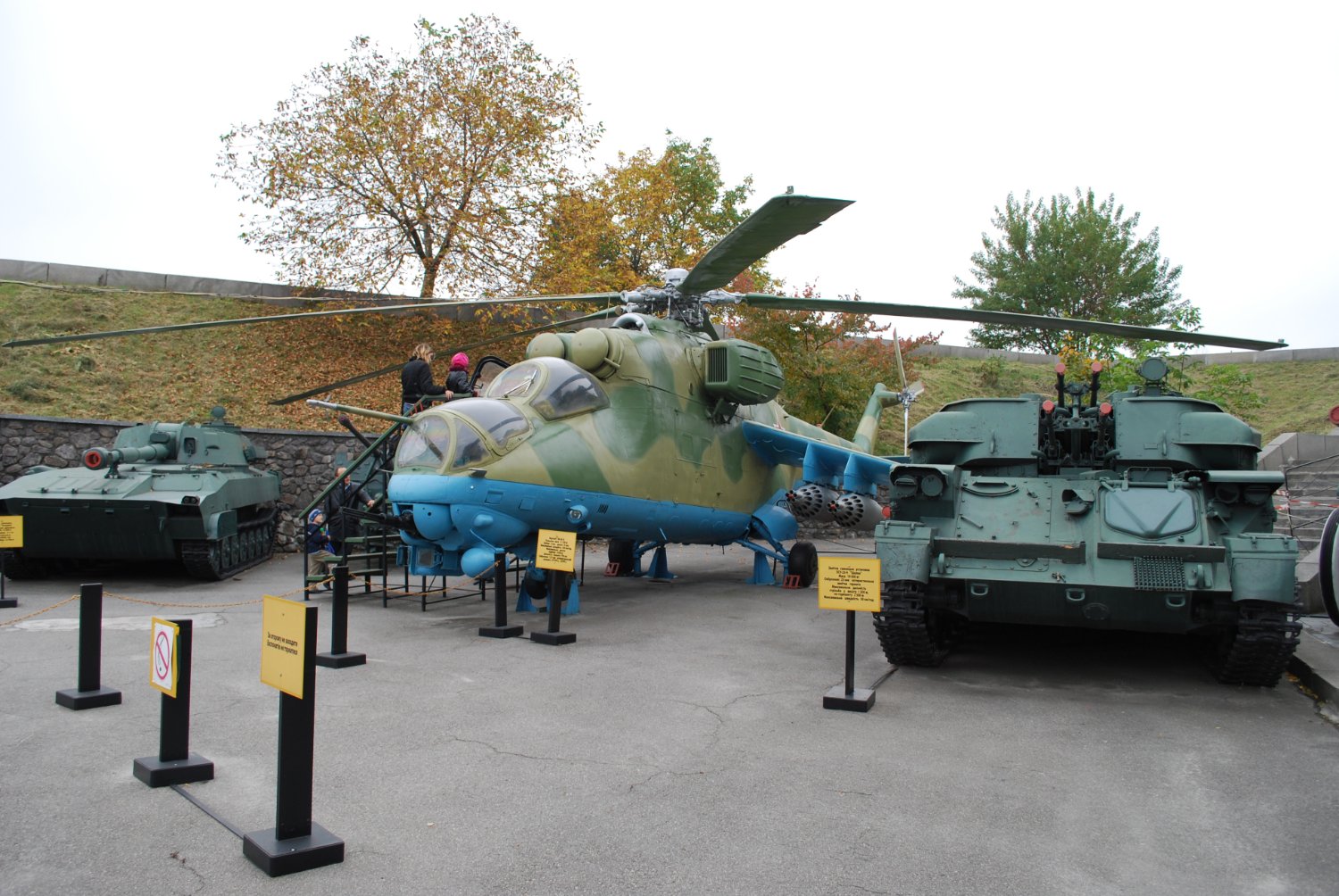
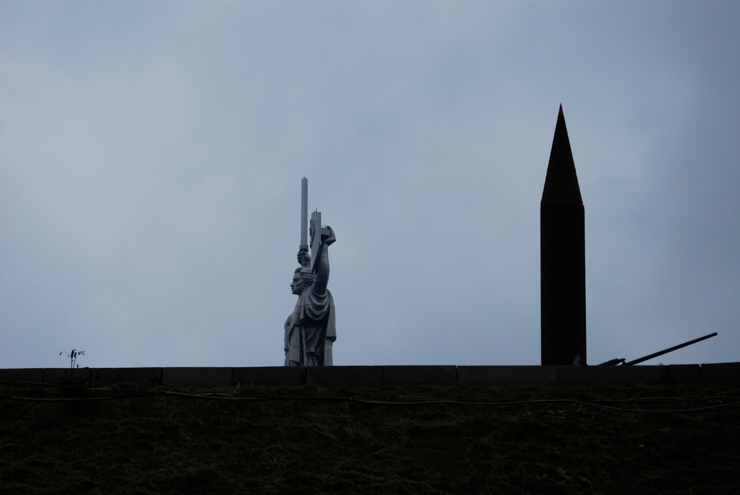
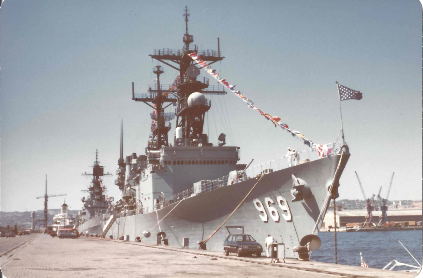
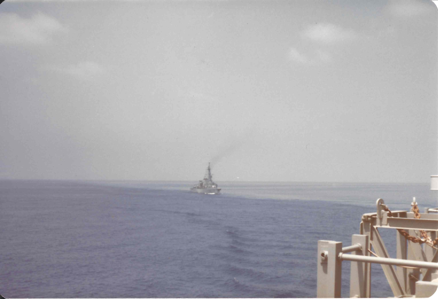
Yeah. I was on USS Peterson (DD-969) as a midshipman. In the summer of '84 we were with a small Marine battle group (Nassau, Ponce, Saginaw) off the coast of Beirut. Periodically other NATO/aligned ships would join for a time, but the Soviets always kept a Krivak around. We watched them, they watched us. One day, we got a good look at them when one of the trash bags didn't sink, and the Krivak immediately put on steam and picked up the bag. Hard to see from here, but it follows the identification slang for a Krivak (Hot dog pack, Smokestack, Knife in the Back, two Guns in the Back), the hot dog pack being the quad launcher for SS-N-14 Silex anti-ship/anti-submarine missiles. As it happens, some of the sailors on the Pete had filled one bag with, ah, unpleasant materials, and intentionally not weighed it down. Childish, I know. For reference, "Pete" with USS Biddle (CG-34) in the background, later, in Marseille (apologies for the quality, they are scanned prints). @ClipperFan or @rwiederrich, I don't know if you've been back behind what used to be the curtain, but it can be really weird for anyone that lived through the Cold War. I was in Kyiv back in 2008 and I visited what is now called the "National Museum of the History of Ukraine in the Second World War" but what was then the "Museum of the Great Patriotic War". They had a display of hardware outside the museum, but in addition to the WWII stuff, there was a bunch of Cold War equipment there as well. Two representative snaps below - an Mi-24 Hind helo and an R-12 Dvina IRBM with the Rodina Mat (Батьківщина-Мати) in the frame as well. As you can imagine it was weird looking at the stuff the Soviets were aiming at us as a display that families came to look at when they visited the memorial and park, and the shield of the Rodina Mat still has the seal of the USSR on it (my understanding is that the Ukrainians want to remove the hammer and sickle, but it's a big job and frankly they have other things on their mind right now). I assume it's just as weird for people who were in Warsaw Pact service who visit the Smithsonian Air and Space Museum (especially the Udvar-Hazy Center) which has an SR-71 spy plane and Cold War fighters and things like Poseidon missiles (and some Soviet stuff as well). When I was walking around Kyiv I wondered if anyone there had been assigned to the Black Sea Fleet back in '84, their HQ was obviously in Sevastopol in the then Ukrainian SSR. George


-
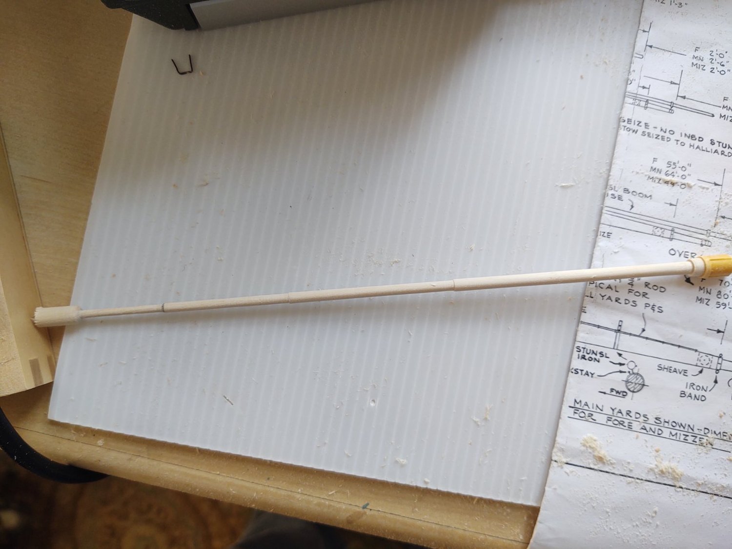
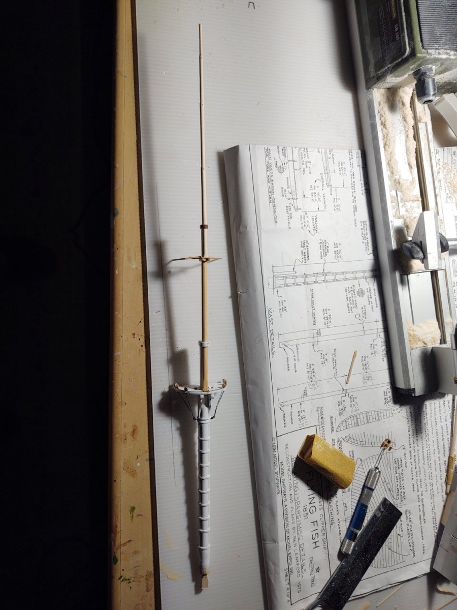
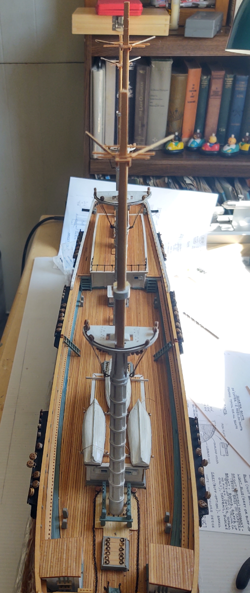
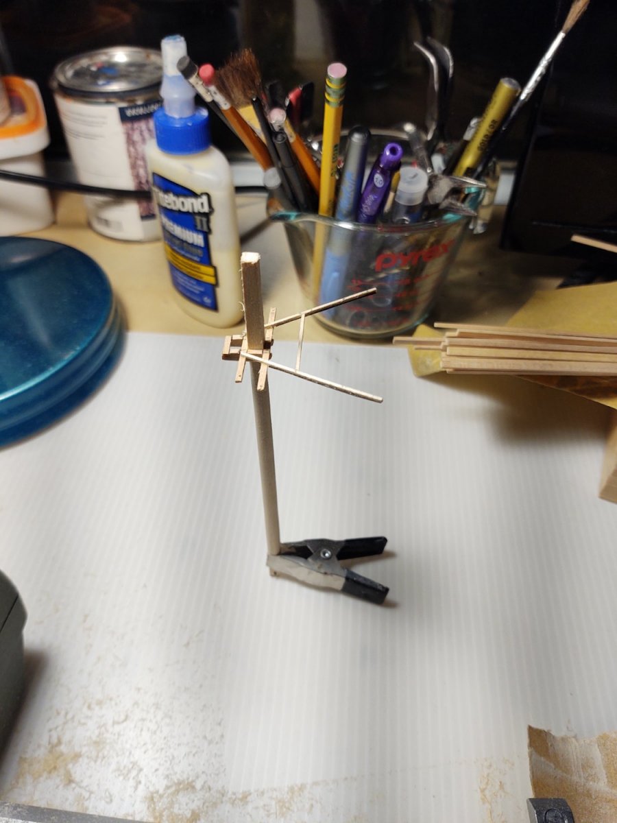
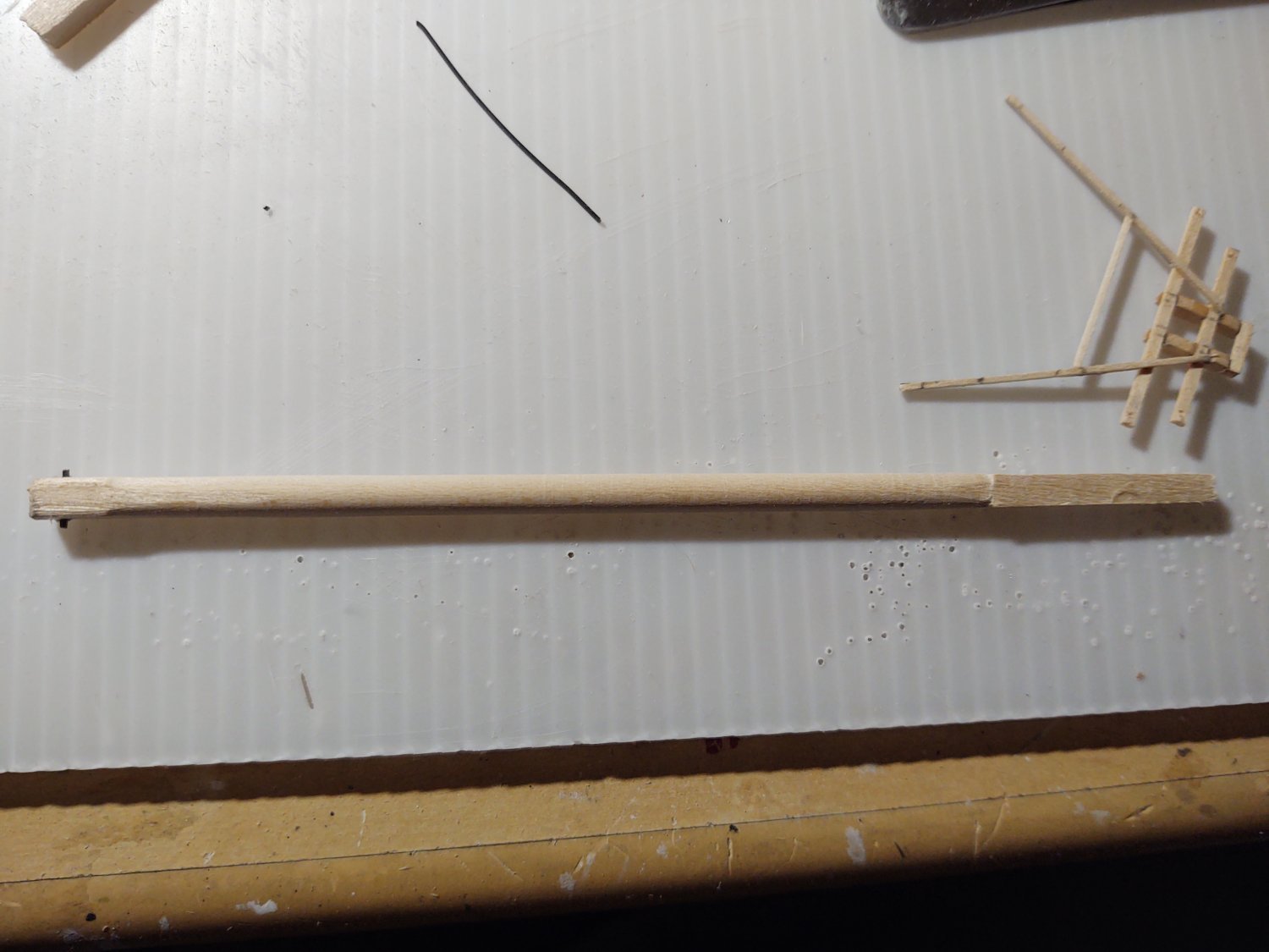
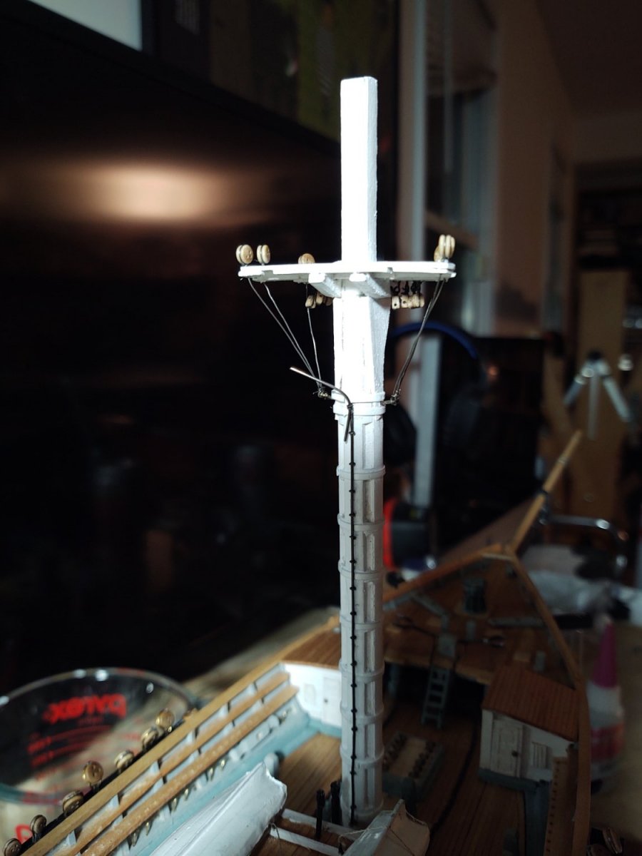
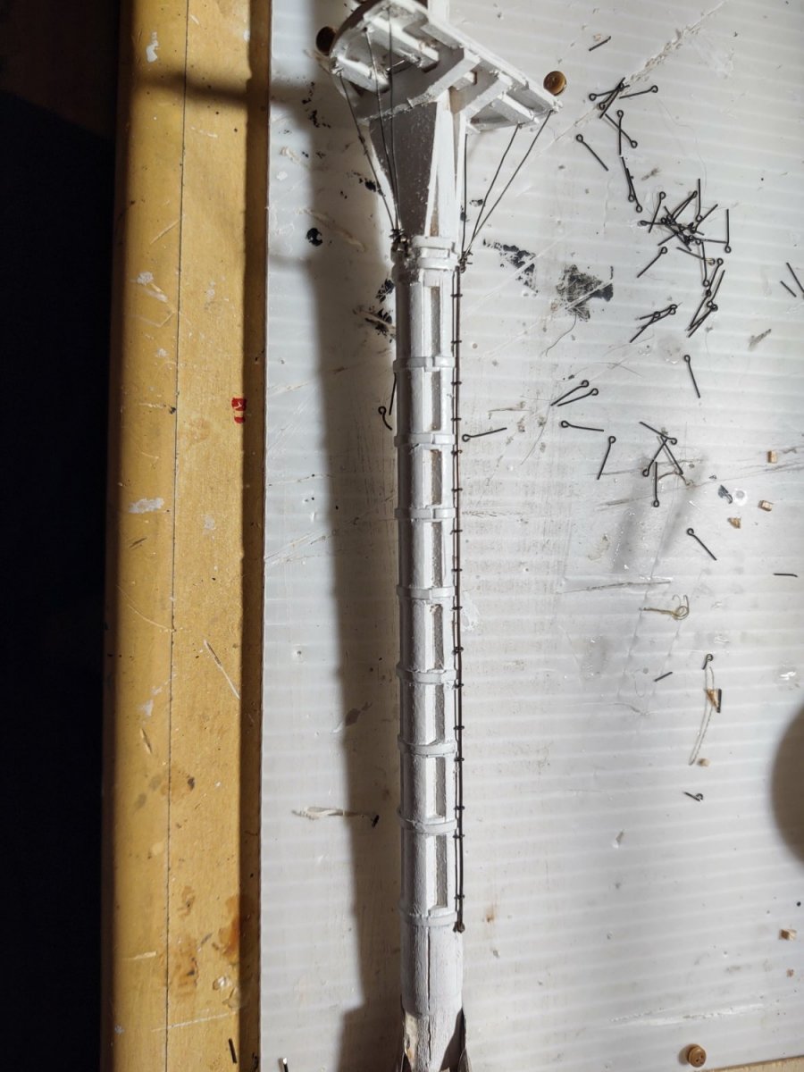
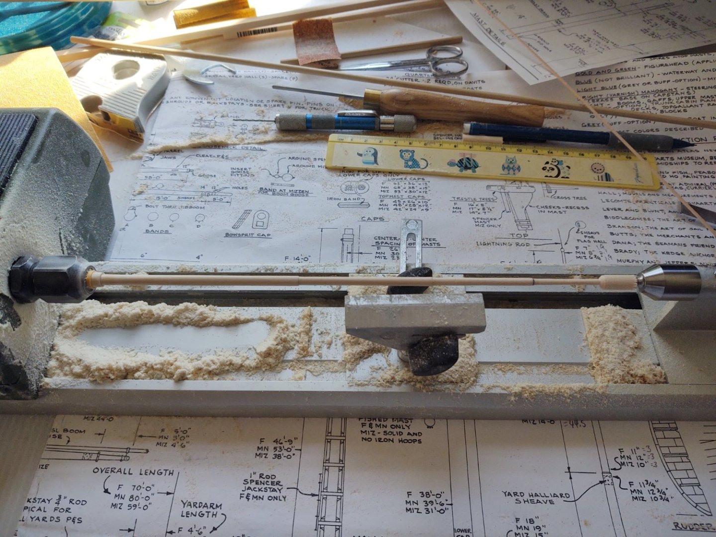
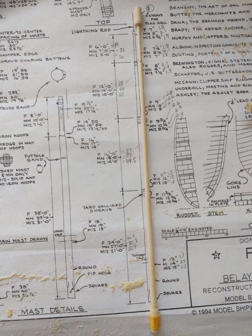
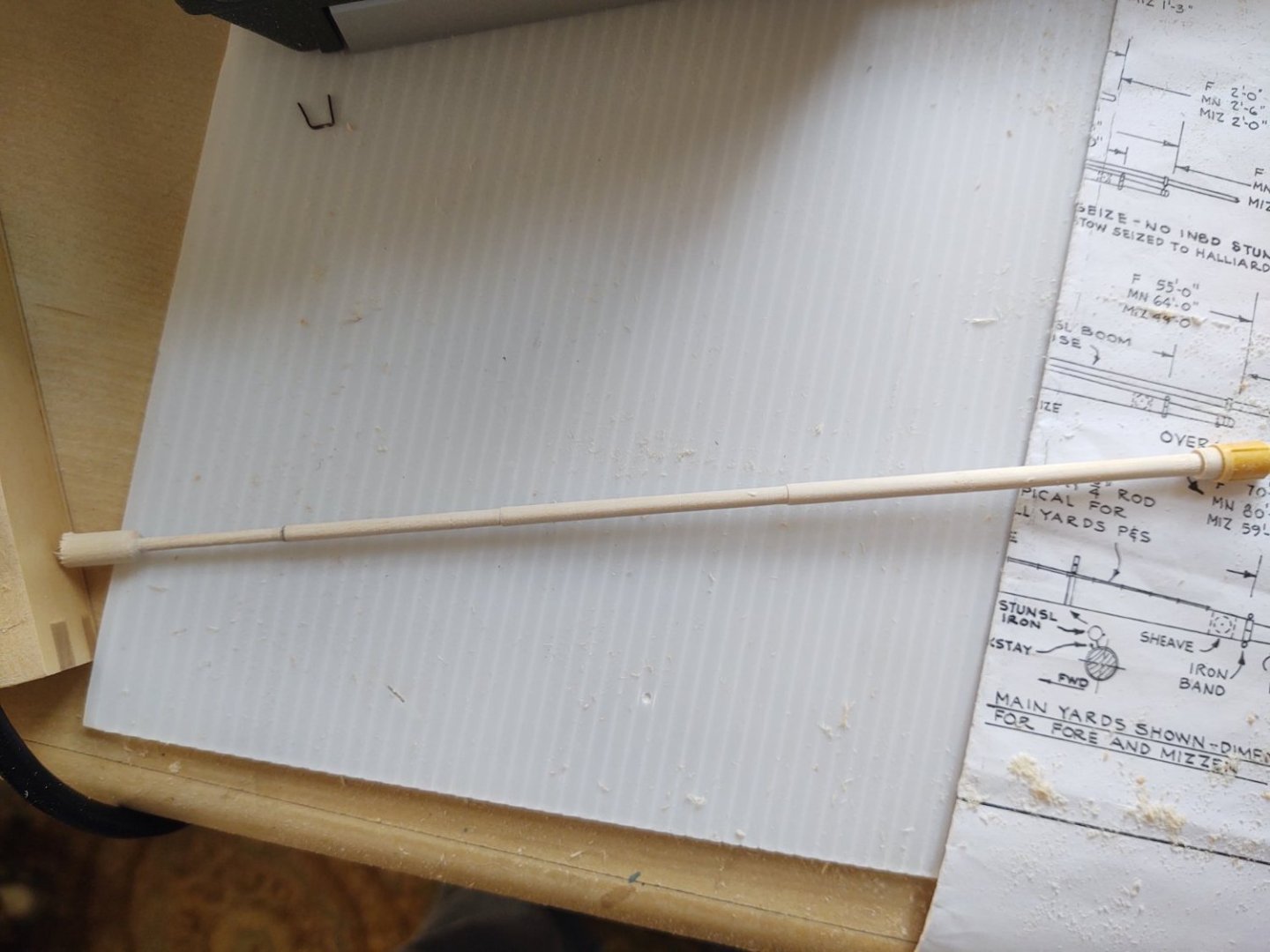
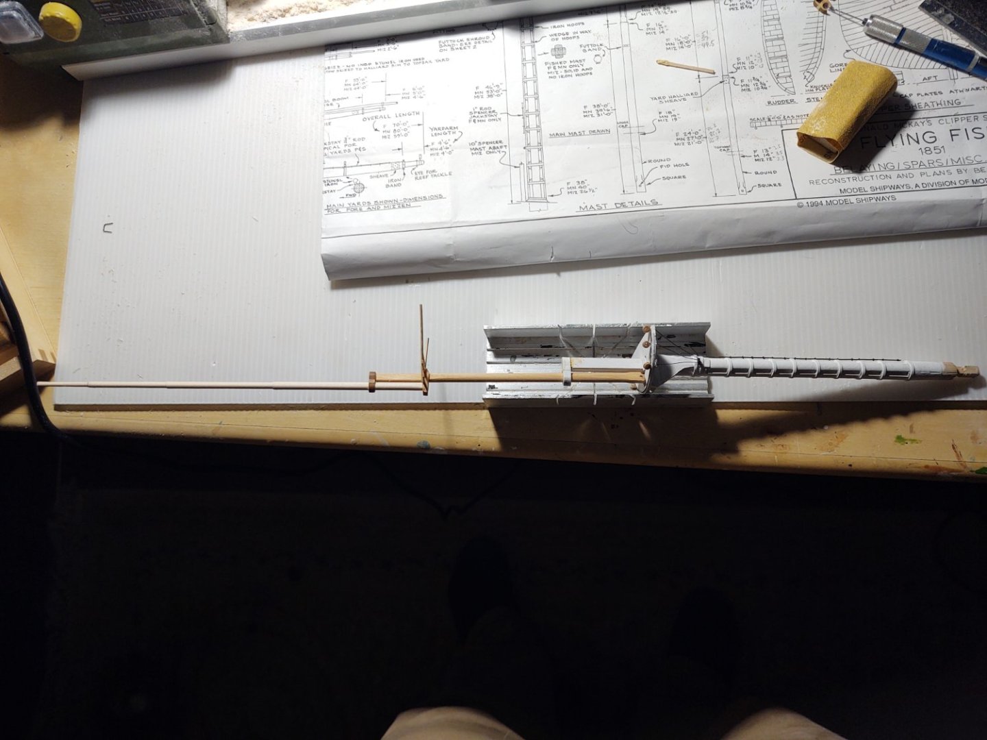
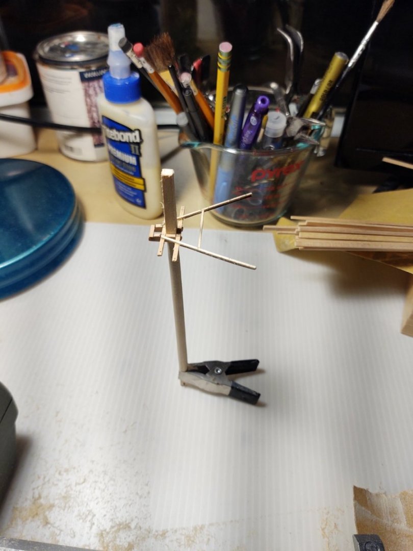
Well, back to the topgallant masts. Each of the previous failures taught me something, the most important was probably that I was not going to be able to use anything other than sandpaper to shape the topgallant masts, that the birch dowels at that length/thickness were not going to be successfully shaped with my cutting tools on the lathe. So, 100 grit paper to get the approximate shape, and 220 to finish it off, I managed to make the following (I did use a pointed cutting tool to square the ends). My goal was to properly capture the stepping of the mast (key to successfully mounting the stays) and I think that i did that: Here are two other views, the first sitting next to the diagram (this is for the main - which is what is shown in the diagram. All the penciled in numbers are just my conversion of the sizes of the real masts into mm) And the second of the piece before I cut the ends off: The Tamia tape on the right side of the picture was just to increase the diameter so that it would fit properly in the collet. I squared the foot of the mast to fit into the appropriate location in the trestle trees, drilled holes for the halyards, and then expanded the size of the hole in the topmast caps, and then trimmed the topmasts to accept the square hole in the cap, and voila, one (partly finished) mast! A couple of views of the mast below, looking directly aft: And looking from the port side, in profile, as it were: And a view from the port side with the mast (precariously balanced, and the topgallant leaning slightly aft because it isn't glued in place) on the ship: Although the plans suggest that the whole mast above the tops should be bright (with the exception of a gilded ball on the truck) the Butterfield painting shows the topmast from (and including) the trestletrees to the cap in white, with the foot of the topgallant also white to the point where it passes through the cap. I don't really see the spreaders in the painting, but I assume that they too are white. So, first stain on the mast itself, followed by some white paint, at which point I can call the spars on the mainmast done. Moving forward, I will need to scratch build a cap for the fore mast as I broke one of the two same-sized caps widening the round opening. That's no big deal, I think that all of the caps on the Niagara (and 1/4 of the ones on the Fish) were scratch built because I had a tendency to break them opening out holes. Good practice for the eventual RRS Discovery (1901) scratch build. This feels like something of a milestone. I'll say this much, the ship is going to take an enormous case, particularly vertically. Somehow paintings don't really give you a feeling for how much sail these things must have carried but when you see just how high the masts go versus the length of the ship - that drives it home. As always, thanks for looking in. Regards, George K


- 602 replies
-
- 8
-
-

-
- Flying Fish
- Model Shipways
- (and 2 more)
-
I wonder how many people my children's age would even get the West Germany reference. Getting old, I guess.
-
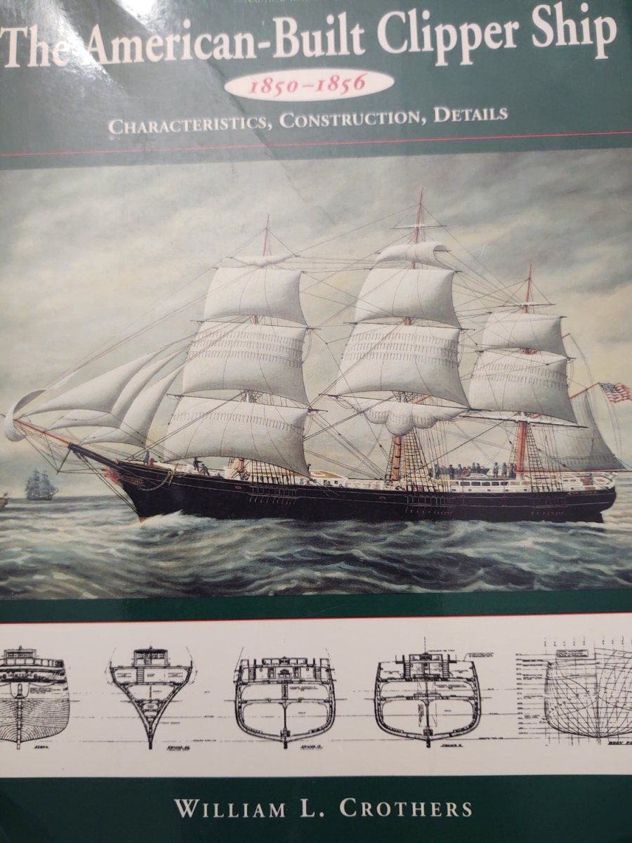
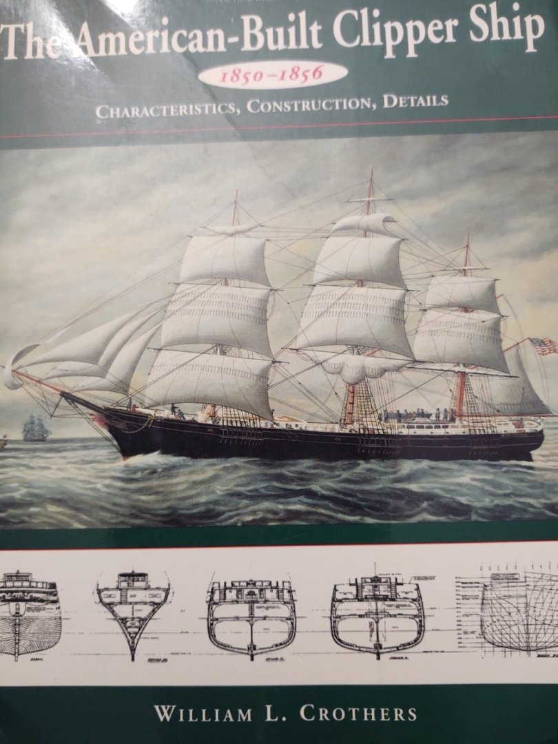
Well, three failed attempts to make the fore topgallant mast today (two breaks, one asymmetry). But this arrived from my one of my favorite bookstores (Powell's in Portland, OR), so not a complete loss. Fun fact from an early look through the book. The green color of my fish was chosen l because according to Steven Ujifusa's book "Barons of the Sea", McKay had originally wanted to paint it that way. Interestingly, on p 344 of the edition I have of Crothers we read that Fearless was painted a green color known as "Tea color" and that this green was used on all of the ships owned by William Weld & Co. Boston. Fearless was built after the Fish, but makes me wonder if McKay saw some of Weld's other ships and got some ideas...
- 602 replies
-
- 2
-
-
- Flying Fish
- Model Shipways
- (and 2 more)
-
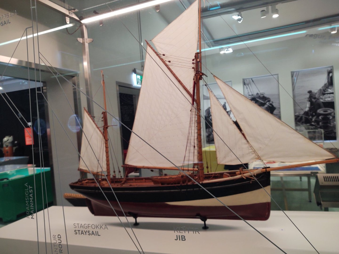
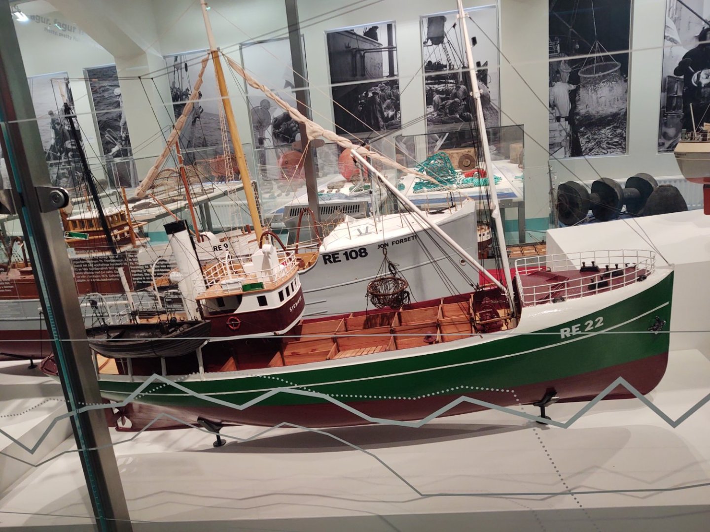
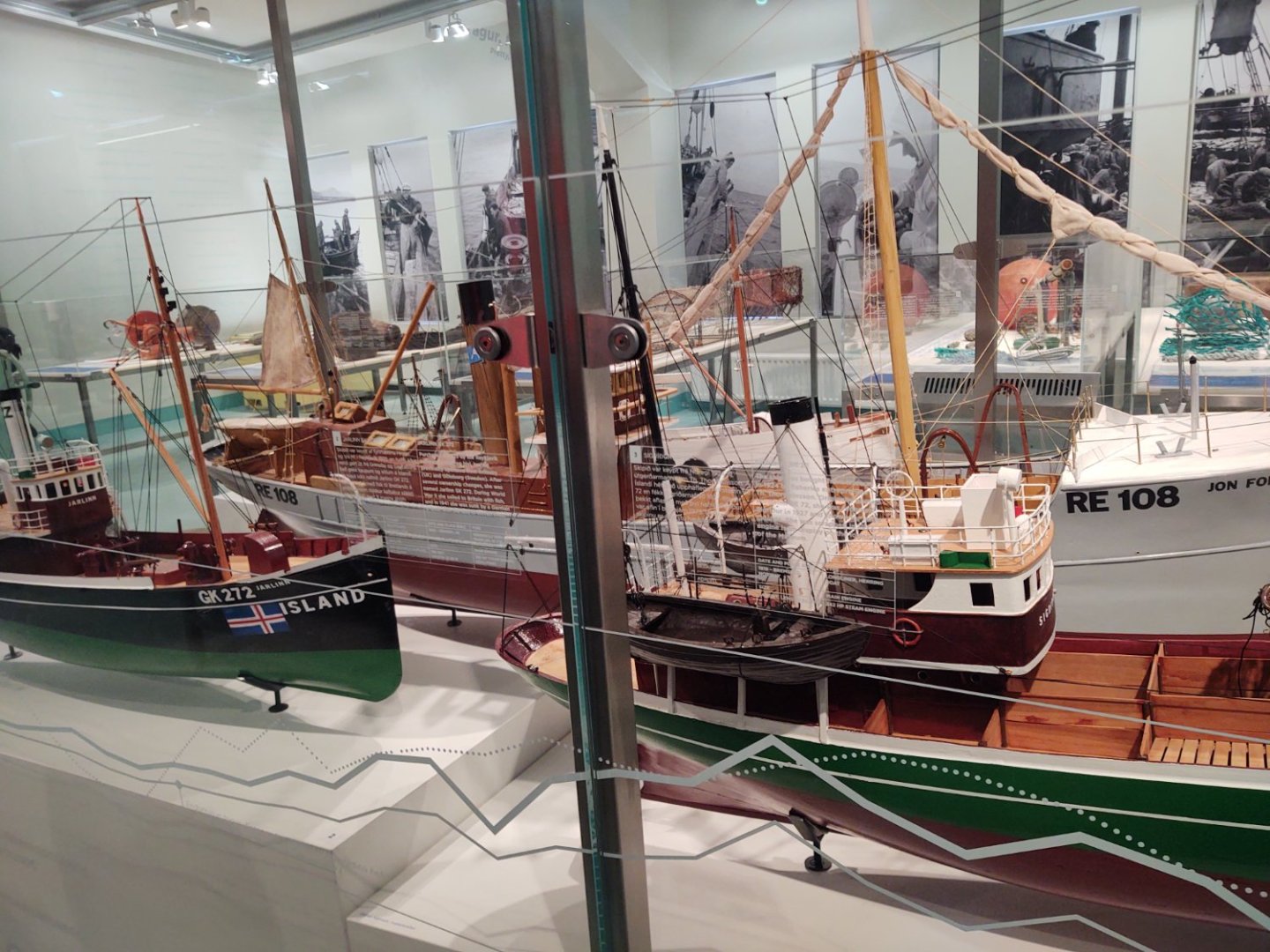
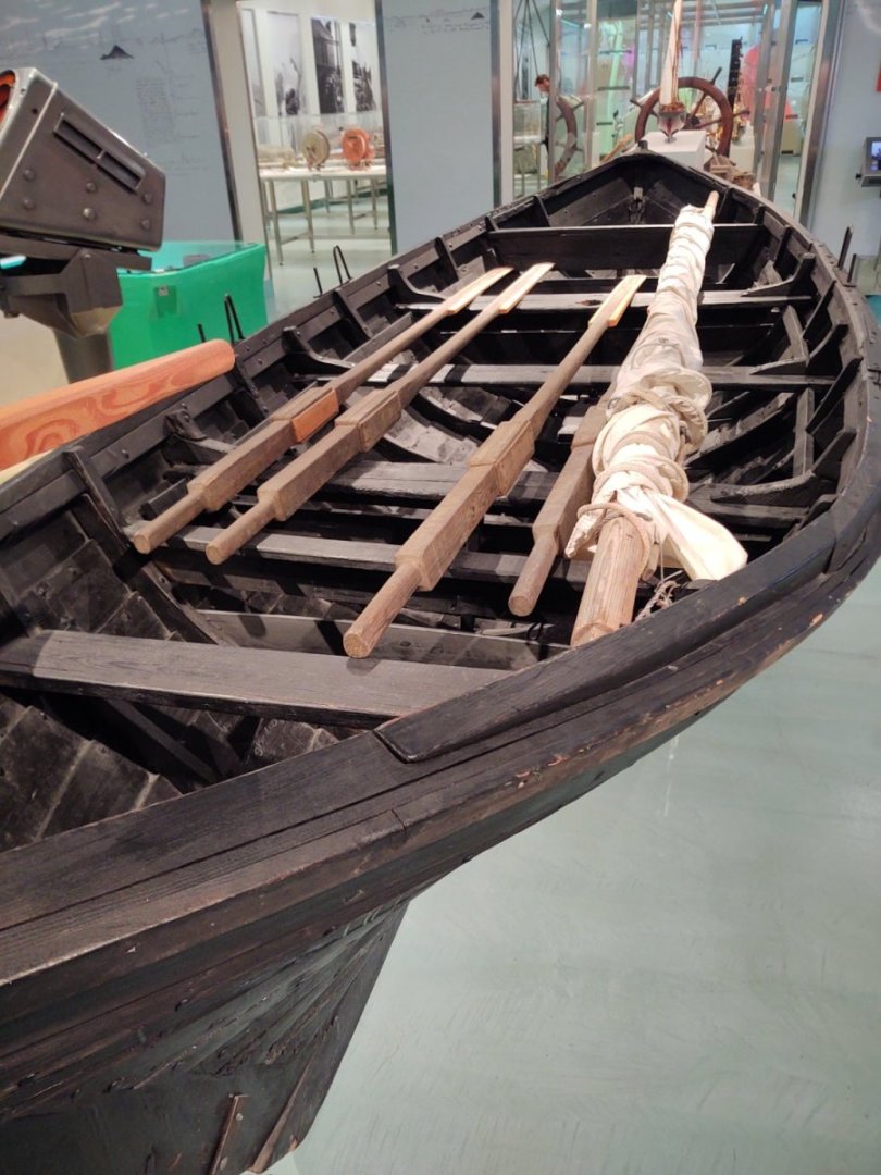
No update for a few weeks (vacation), but here are some lovely model ships (and one real boat) from the Reykjavik Maritime Museum. No hints as to where I might be 🙂. George K
- 602 replies
-
- 3
-
-
-
- Flying Fish
- Model Shipways
- (and 2 more)
-
Yeah. Gonna have to stick a crowbar in my wallet and get one or both ...
-
That seems consistent with the plans and what photos I could find. The practical upshot is that I'm not going to install the chocks (if at all) until I see where the stays land on them. Better that they flow and maybe stick out slightly from the spreaders than have them bend oddly. In a month or so, I'm guessing I'll see how closely I actually followed the plans when the first topgallant stay is set. Thanks, George K P.S. It's sad to hear that you are looking for a buyer for BlueJacket. I wish you the best of luck finding a someone to continue it's wonderful operations and you the best in retirement.
-
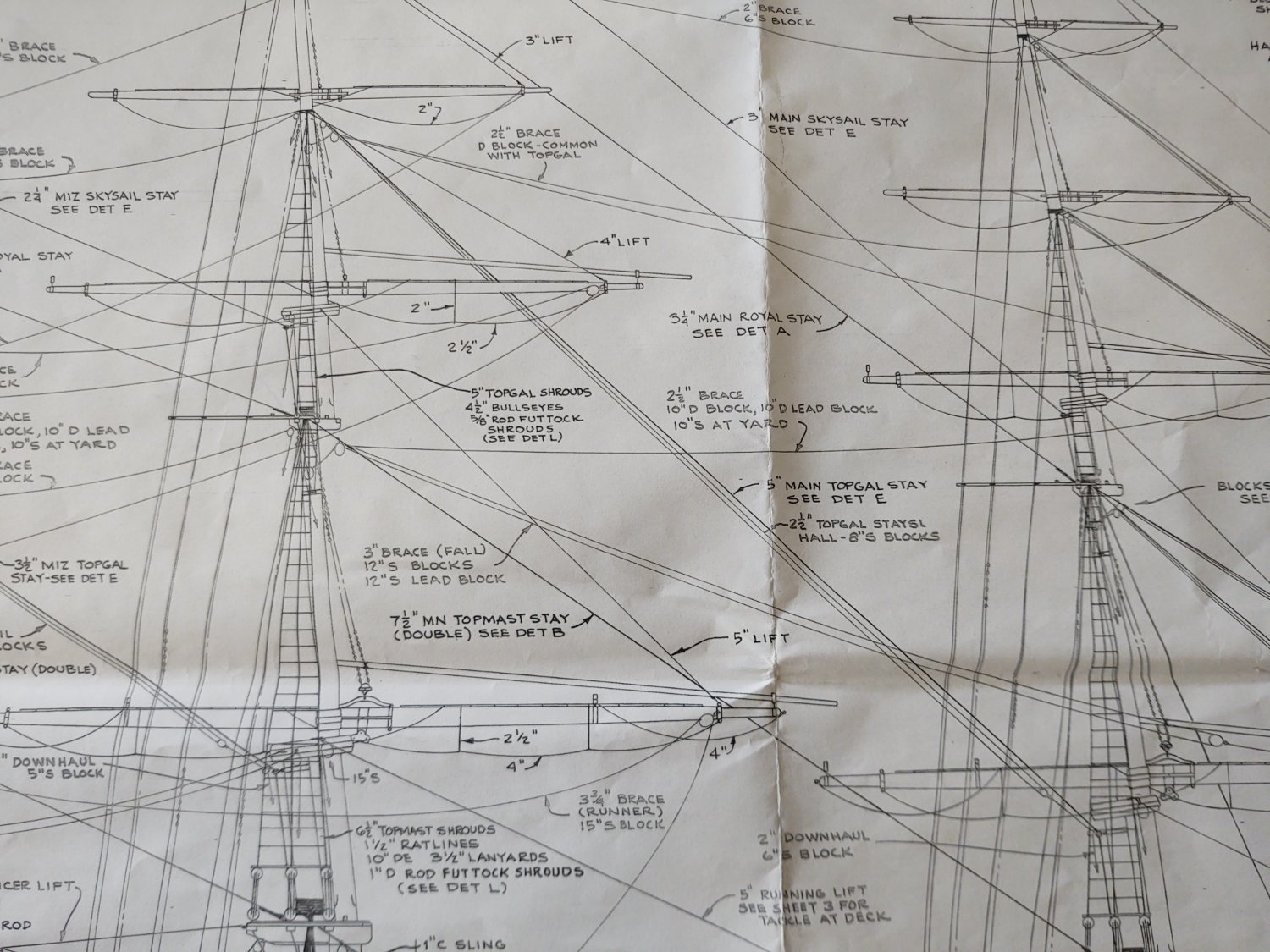
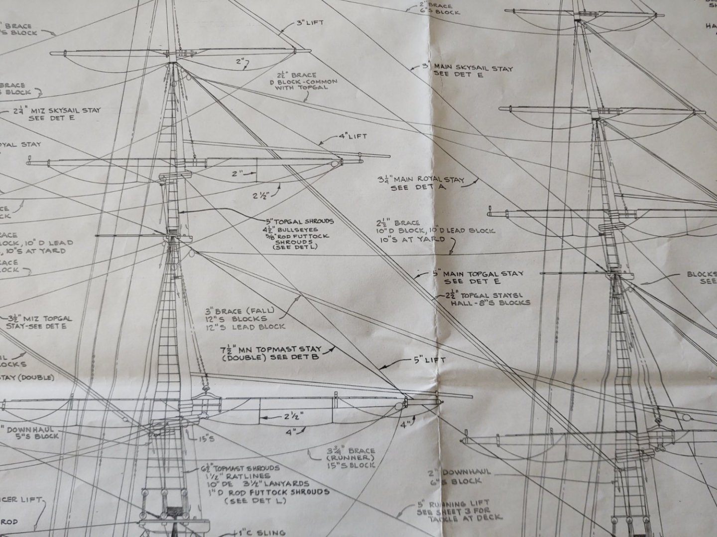
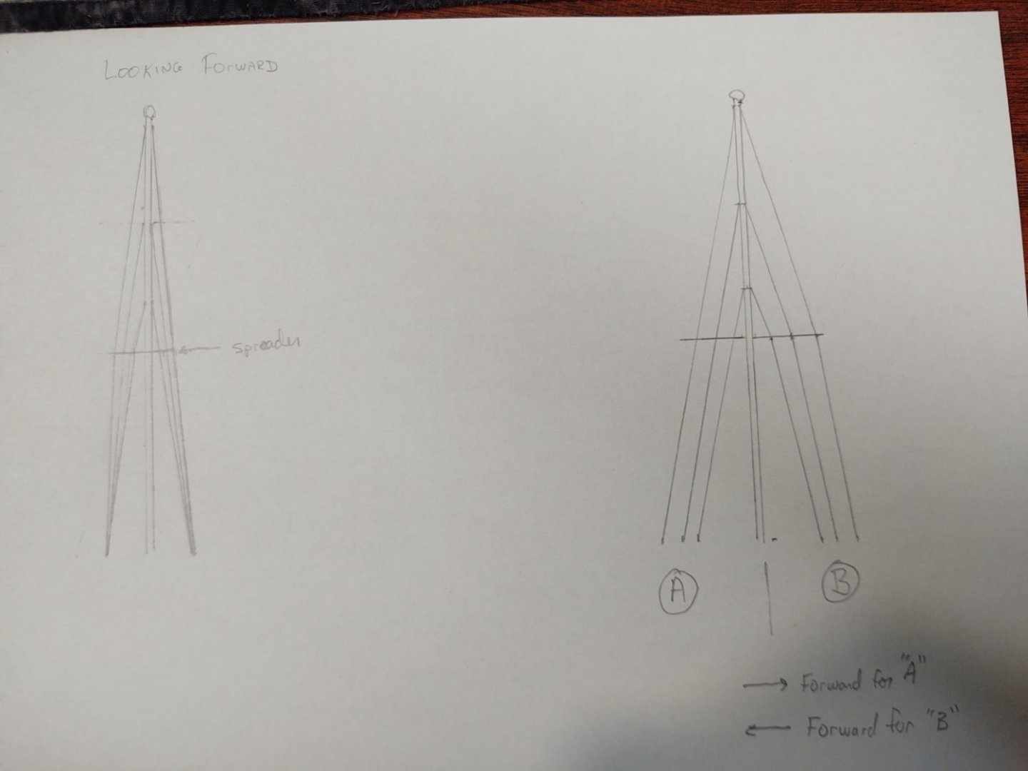
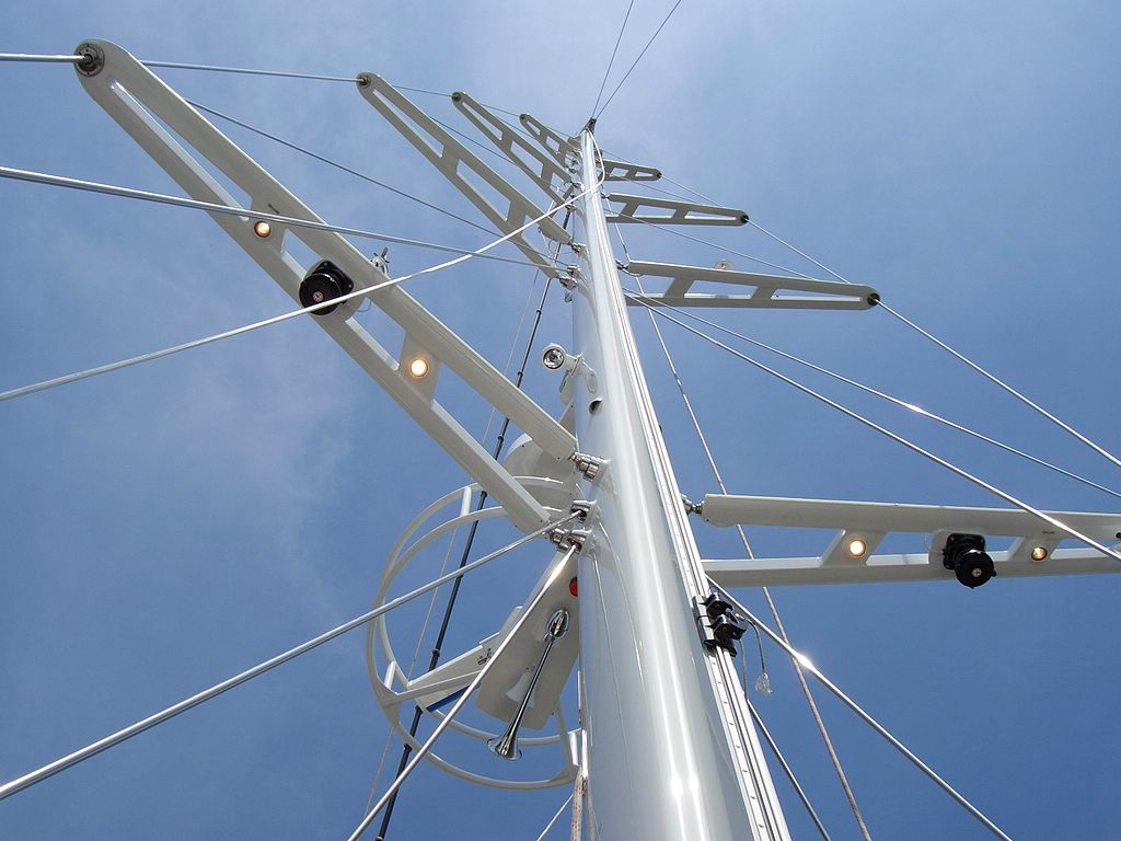
Thanks all. To try to clarify my question, here is a segment of the plans. It shows (I think) that the spreaders are not changing the flow of the backstays. Now, here is a drawing I made to show the question I'm wondering about. On the left you have a mast viewed looking forward and on the right you have a mirrored mast from the side. On the looking forward view you have two options: on the left side, the spreader changes the direction of the stay, on the right, it hits it naturally and just kind of helps keep the stay in place using its natural flow. On the right, you have the same situation (although I realized it is the opposite as on the other drawing). On the left, the spreader is just sitting where the path of the stay naturally falls, and on the right, it changes the direction of the stay. This is a public domain image from Wikipedia showing a (modern) spreader - as you can see they are changing the flow of the stay: Again, my read of the plans says that this isn't what is going on - that it is following the natural path of the stay - but would appreciate anyone's insights. In either case it would prevent interference, but it will drive where I put the chocks. Thanks again, George K
-
Good luck. My father in law had back surgery 25 years ago and it really helped. Hopefully the same for you. George K
- 481 replies
-
- 2
-
-
- Cutty Sark
- Revell
- (and 2 more)
-
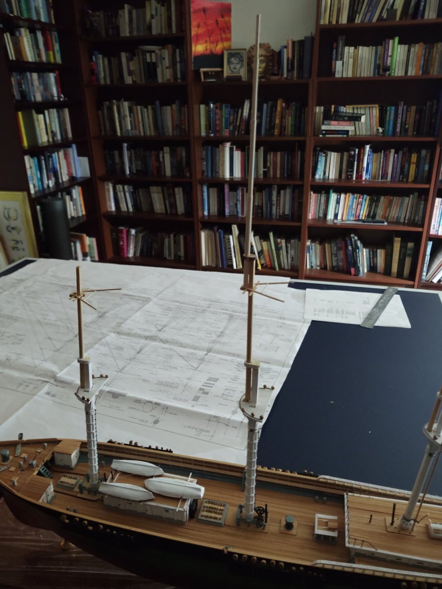
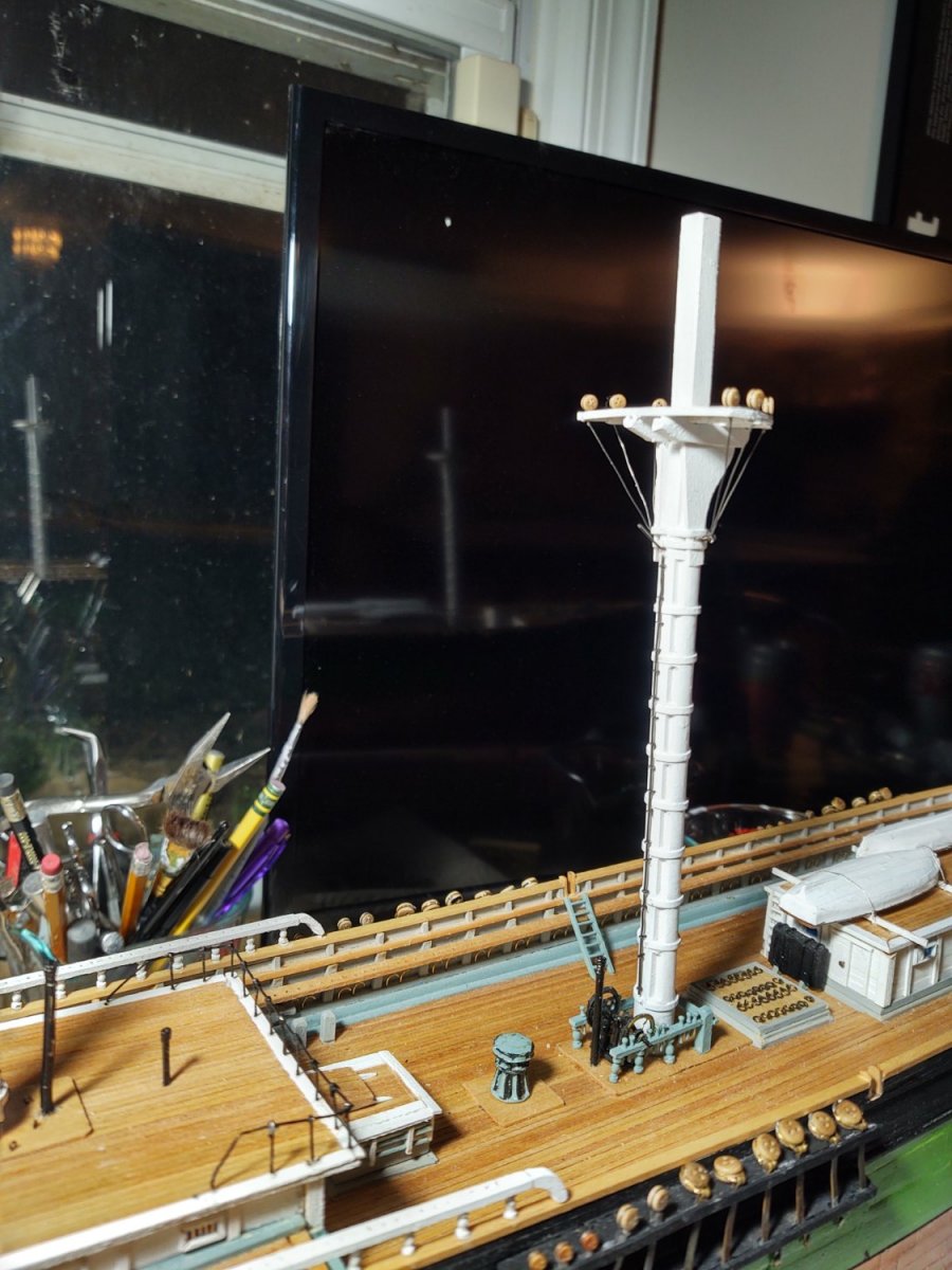
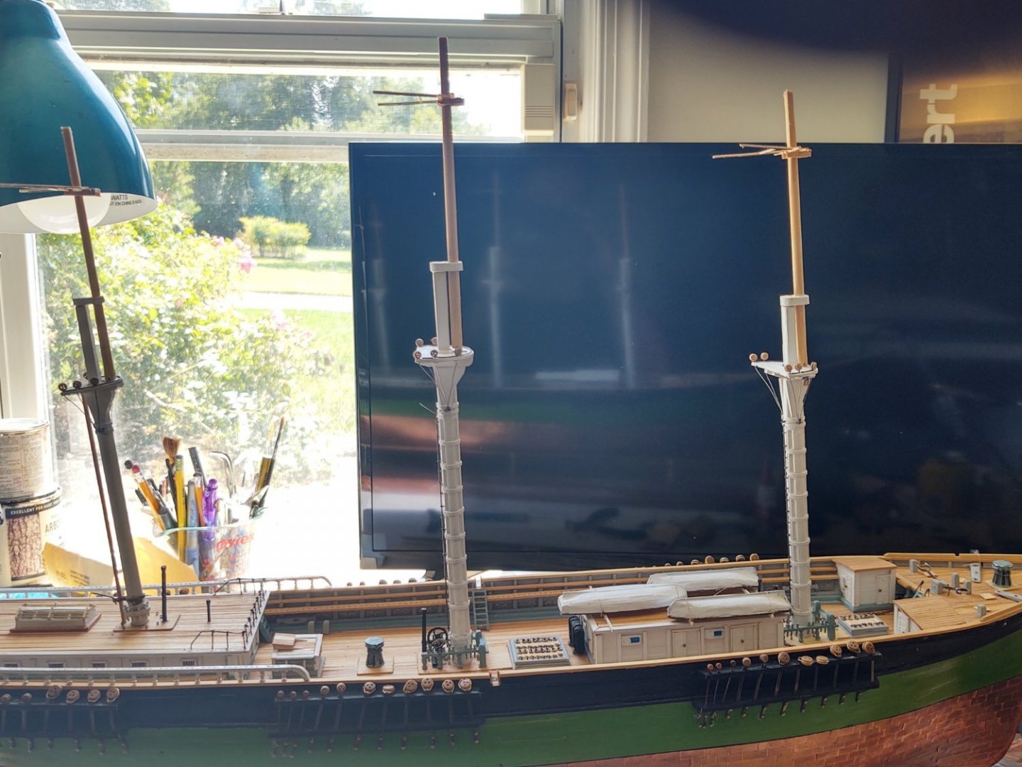
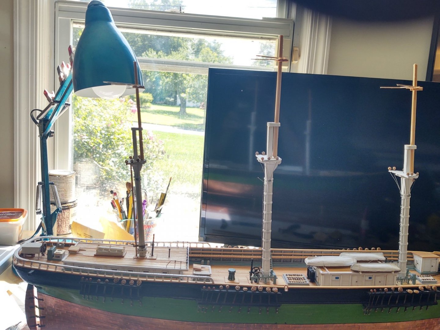
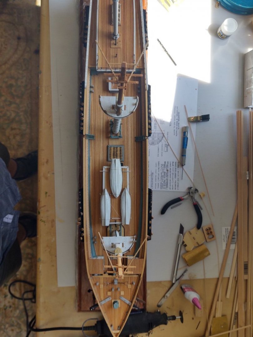
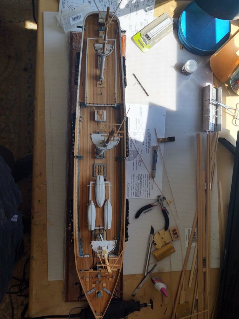
Happy 4th! An update on construction. The topmasts are all completed and mounted on the tops, the caps are painted and secured and we have three nice and straights masts. Finally all of the spreaders are complete (although they are not current glued to topmasts. Some photos. From the sides: From above: And from forward: One quick question to anyone in the know. Regarding the chocks on the spreaders. Are they placed in specific locations to direct the flow of the backstays at a particular location on the spreader, or are they located where the backstays naturally fall and are just there to keep them from slipping? As always, thanks for looking in! George K


- 602 replies
-
- 4
-
-
- Flying Fish
- Model Shipways
- (and 2 more)
-
It is Rich ( @ClipperFan) that reached the milestone, not me. So far, I've been lucky, and only needed some minor knee surgery. But +1 on your wishes for him! And thanks for the vote of confidence on the ship!
-
Didn't even realize you had surgery. Glad to hear you hit the first of hopefully many anniversaries!
-
1/200 Trumpeter IJN YAMATO - issued by MRC/Gallery Models
gak1965 replied to yvesvidal's topic in REVIEWS: Model kits
They are very technical but I think they are pretty good. For most of the classes, he has diagrams (mostly side views) and lots of photos.- 104 replies
-
- 4
-
-

-
- MRC/Gallery
- Yamato
- (and 1 more)
-
1/200 Trumpeter IJN YAMATO - issued by MRC/Gallery Models
gak1965 replied to yvesvidal's topic in REVIEWS: Model kits
The Mogamis were designed as a result of the limitations imposed by the London treaty which left the Japanese with a relatively small amount of cruiser tonnage and a desire by the Naval staff to nonetheless cram as many weapons onto the platform as possible. They used new welding technologies instead of riveting (in common with lots of navies) to save weight but the first ship (Mogami) was a disaster when it went into sea trials. It was badly overweight, top heavy (and so had stability problems) and the hull was so badly bent during the trials that it affected the ability to train the guns Eventually, the first two were reconstructed and the third and fourth built to a revised standard based on the reconstructed earlier units. The whole story (and how the Royal, French, Italian, US and Japanese navies designed interwar ships) is told in a set of books written by John Jordan, called (with excellent truth in advertising) "Warships after Washington", and "Warships After London". The books are interesting from the standpoint of how each Navy responded to the challenges of meeting their military needs within the framework of a treaty that put constraints on what they could design and build. Let's just say that the Mogamis weren't the only poor design to come out of the five countries due to the combination of treaty and technological limitations of the day. George- 104 replies
-
- 4
-
-
-
- MRC/Gallery
- Yamato
- (and 1 more)
-
I admire that you are making your own eyebolts and those shackles are amazing. How did you the wood parts in? Was there enough flexibility that you could pop the (former) deadeyes in and have the shackle retain it's shape? I think your cathead ornaments are great. Anything at 1:96 is going to be challenging, and I had a time making a simple star from copper tape - those are much better! George
-
Offhand I'd say you were setting your priorities appropriately! Congratulations, indeed! May you have a long and happy marriage! George K
- 602 replies
-
- 2
-
-
- Flying Fish
- Model Shipways
- (and 2 more)
-
Part.of the problem may be that the shrouds on your test jig aren't under the same amount of tension as the shrouds on the ship, and that tension helps prevent hourglassing. In addition, with my Niagara I clamped two pieces of wood strip on both sides of the shrouds about an inch above where I was working to fight the tendency of the knots to pull the shrouds in. I wouldn't bother with clove hitches. The scale is so small that almost no matter how good you are, they are going to look too big. At 1:150, a 0.3 mm tall knot (probably the best you can do with 0.1mm thread) is 1.75 inches at scale. I'm with Roger, go with simple overhand knots, secure with some glue or whatever. They won't tug on the shrouds as much and they won't be nearly as bulky. Looking great! George
-
This is probably a really dumb question, but do you know why Maris Stella chose 1:63 rather than 1:64 which, which, while somewhat arbitrary, at least makes sense to convert at scale using imperial units? Regards, George
-
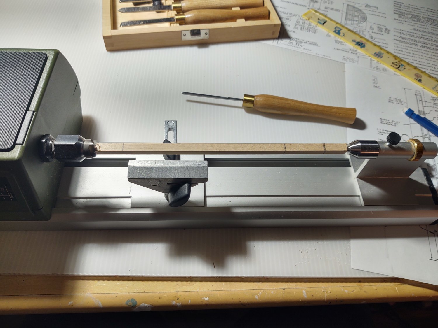
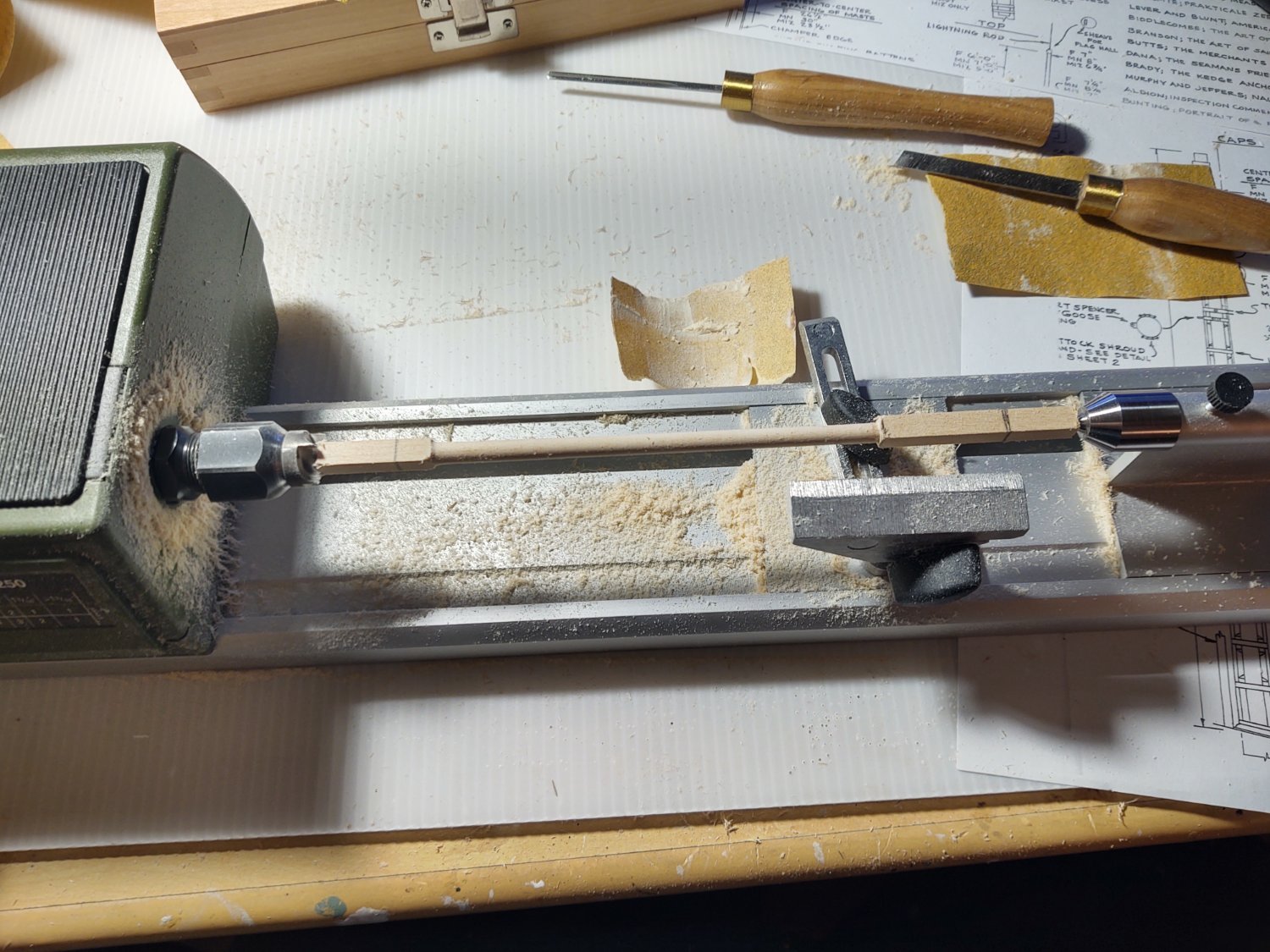
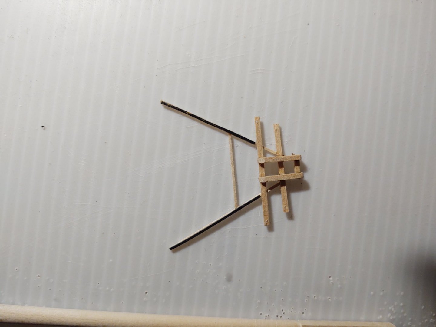
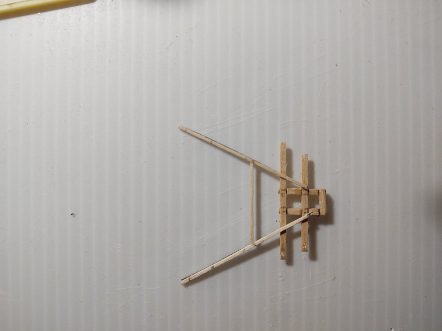
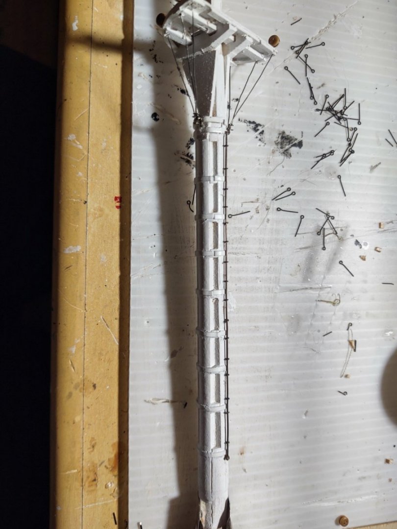
I've started making the topmasts, beginning with the main. Rather than use the kit supplied dowels, I'm starting with larger square stock. For the main that means 3/8 square basswood which I am going to turn and then trim to size. So, the stock on my lathe, marked up to show (left to right) the bottom of square portion of the mast, the end of the round segment, and the end of the square segment. I added a mark (after this picture was taken for the beginning of the round section of the mast. Here is the mast after turning. You will note that the square ends are way too big, as the lower part of the mast should be about 1/4" square and the upper about 3/16" square. This was the expected outcome of this step. Next I took some 100 grit sandpaper and narrowed the square segments so that they were correctly sized, drilled holes for the fid, and made it from two sections of 1/32 x 1/64" blackened brass. The mast is shown below. Once I'v built all three, I'm going to stain it so that it is a little darker. Next the trestletrees, crosstrees, and spreaders. These were made out of boxwood stock. In order to get the the crosstrees to be properly aligned on the trestletrees, I dremeled the cutouts with a cutting blade while the two trestletrees were clamped together. The crosstrees themselves are made from 1/16" x 1/32" stock, and quite flimsy before they were mounted. The spreaders are only 3" square in real life (1/32" at scale), and I was very worried about the loads that they were going to be under. So, I took some blackened 1/64" x 1/32" brass and glued it to the bottom of spreaders. You can see the this in the next two photos of the trees and spreaders from above and below (the marks are where I need to put the cleats and will be removed). The brass is barely visible, and I may put some on the brace as well. As with the mast, once all three are made I'm going to remove all the pencil marks and stain them. I haven't decided yet if I am going to make the six cleats out of wood (they would be really small and fragile) or put an opened jackstay eyebolt or perhaps a bit of very fine wire. They are going to be sufficiently hidden by rigging that I'm inclined to simplicity. I wanted to get an idea what the whole assembly will look like on the model, so I slipped them onto the mast, and I have to say I am reasonably pleased. Thanks again for looking in! Regards, George K.


- 602 replies
-
- 8
-
-
- Flying Fish
- Model Shipways
- (and 2 more)
-
1/200 Trumpeter IJN YAMATO - issued by MRC/Gallery Models
gak1965 replied to yvesvidal's topic in REVIEWS: Model kits
When I was a boy, my grandfather built the 1:200 Nichimo version with the lights, working props, etc. I don't know what happened to it ( it got lost sometime in the intervening 52 years) but I've scanned ebay more than once for one of them. May need to make the investment, although goodness knows where I'd display it. at least it wouldn't be as tall as the sailboats so, lower case height.- 104 replies
-
- 6
-
-
- MRC/Gallery
- Yamato
- (and 1 more)
-
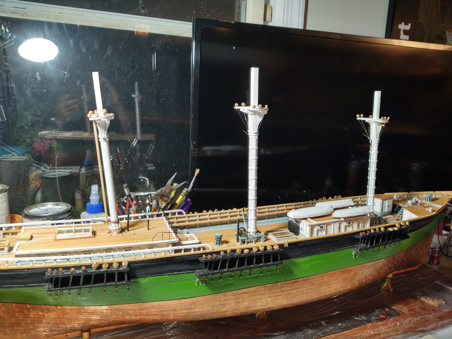
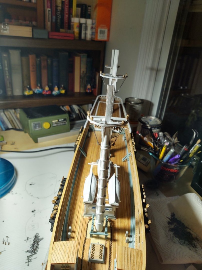
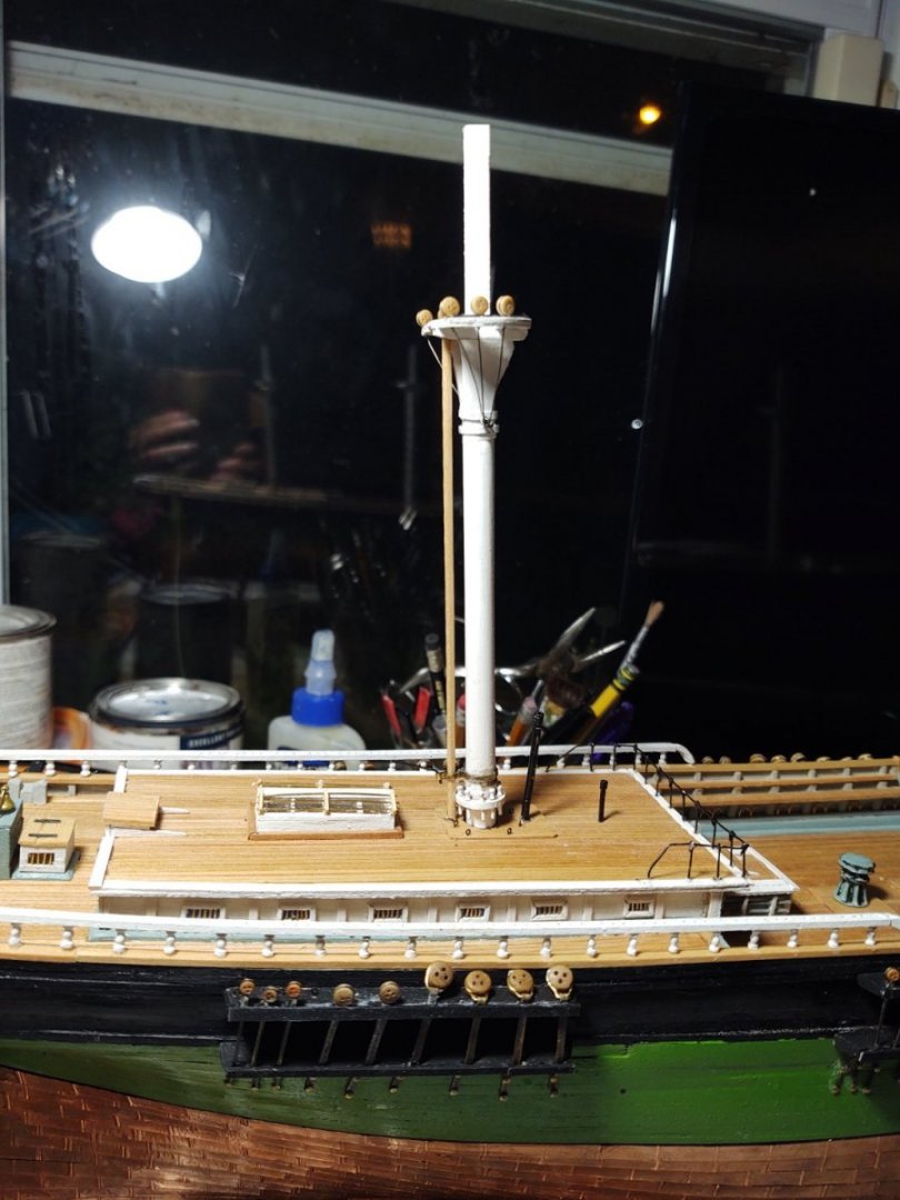
Well, an update. I've been working on the lower masts while I finish odds and ends on the deck. Lots of photos for me (well 6) but we are in a period where many things get done but the ship doesn't change much in overall appearance. With additional paint, the main was painted, and it is time to start adding additional details, including the iron reinforcing on the tops and the holes for the fairleads. The first new thing that needed doing was the spencer jackstays on the fore and main masts. They are theoretically 1" or 0.01" at scale. I built mine from 24 gauge black steel wire and 0.75 x 6 mm brass eyebolts that were chemically blackened. That would make them about 2x scale, but it isn't terribly noticeable. The jackstays on the yards were smaller and I will likely use a finer wire when I make them. Here is the foremast with the spencer jackstay. Next I made the futtock shrouds from deadeyes and some fine gauge black wire. The ends were threaded through the pre-drilled holes in the top and attached to a large eyebolt that is filling in for the individual mounting points on the relevant iron. Finally I drilled a hole in the masts for the gaffs and mounted a piece of 24 gauge wire that will eventually become the gooseneck. I have seen people use circles cut from blackened copper tape to make fairly convincing hinges at this scale and that is the plan for these gaffs. Here are photos of the fore and main masts with the jackstays and the futtock shrouds. This picture also shows that I installed the amidships ladders. I ultimately used the castings, they seemed as good as I was likely to make on my own, and (on the fore) that I've started installing the blocks for the bunt and clew lines. Ideally the blocks would be of four sized (two different sizes on the main/fore) and a second (smaller) set of two sizes on the mizzen. The kit comes with three sizes of single block and functionally all 4 block sizes were closest to the 3/32 inch size - so all 24 will be the same size. The mizzen required a spencer mast, which I built from a dowel and a some strip brass bent to accept a 24 gauge wire that will be the gooseneck, the spencer and then wraps around the lower mast. I also added the futtock shrouds, and here is a photo: So, the ship looks like this now with all of the masts in place (but not yet glued in). The mizzen is slightly more raked than I want, but the picture makes it look worse than it is. I am going to get in there with my Dremel so that it will stand at the same rake as the fore and main. Finally, a view of the ship from the bow showing the masts which. Again, the alignment appears a little off because they have no shrouds and are not glued in place. Next up - on the right of the final photo you can see the brass belaying pins that I hit with some patina. I think I need to give them another treatment to make them more uniform, but otherwise they are ready to be placed. Finish stropping the rest of the blocks that are mounted on the tops (16 down, 8 to go) as well as a couple of blocks for the mizzen braces that mount on the top, and then it's time to make the topgallant masts. I build (but don't rig) the entire mast before doing it's final mounting and starting to put the shrouds in place. Hopefully that time will start to come soon. In the interim I will probably start to rig the boswsprit to give me another area to make some obvious progress. As always, thanks for looking in and the encouragement. Regards, George K


- 602 replies
-
- 8
-
-
- Flying Fish
- Model Shipways
- (and 2 more)
-
I wound up chickening out on my Passat. 1 fewer mast but at 10/inch, what a mess. And the Heller Ratline maker was a joke. One thing to check, the current Passat only has ratlines on 3 of the shrouds per mast, did Preussen use them all or did they only use the inner ones? I don't think people went aloft as much on the newer windjammers as compared to say a 19th Century warship