HOLIDAY DONATION DRIVE - SUPPORT MSW - DO YOUR PART TO KEEP THIS GREAT FORUM GOING! (Only 20 donations so far - C'mon guys!)
×


gak1965
-
Posts
720 -
Joined
-
Last visited
Content Type
Profiles
Forums
Gallery
Events
Everything posted by gak1965
-
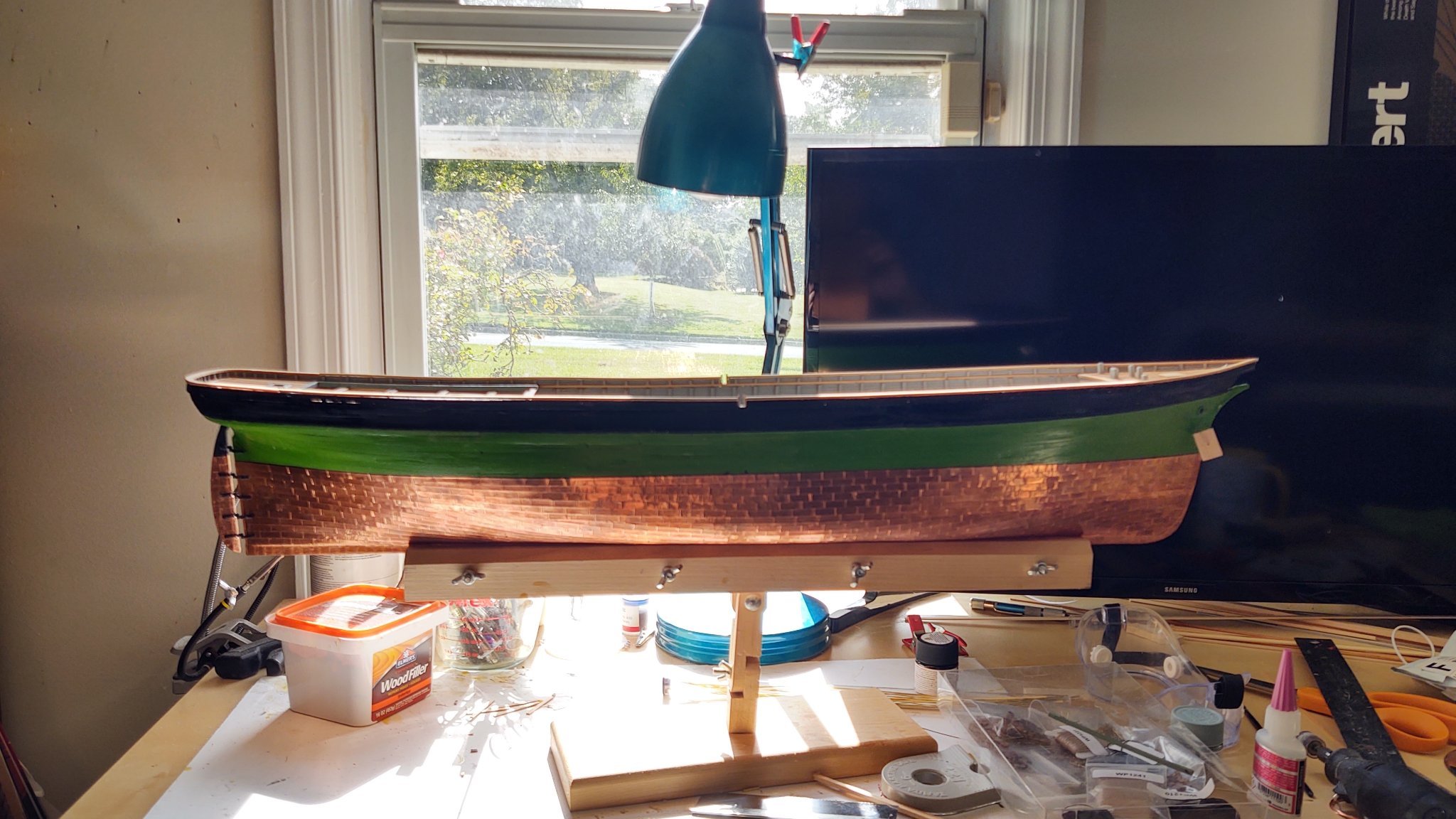
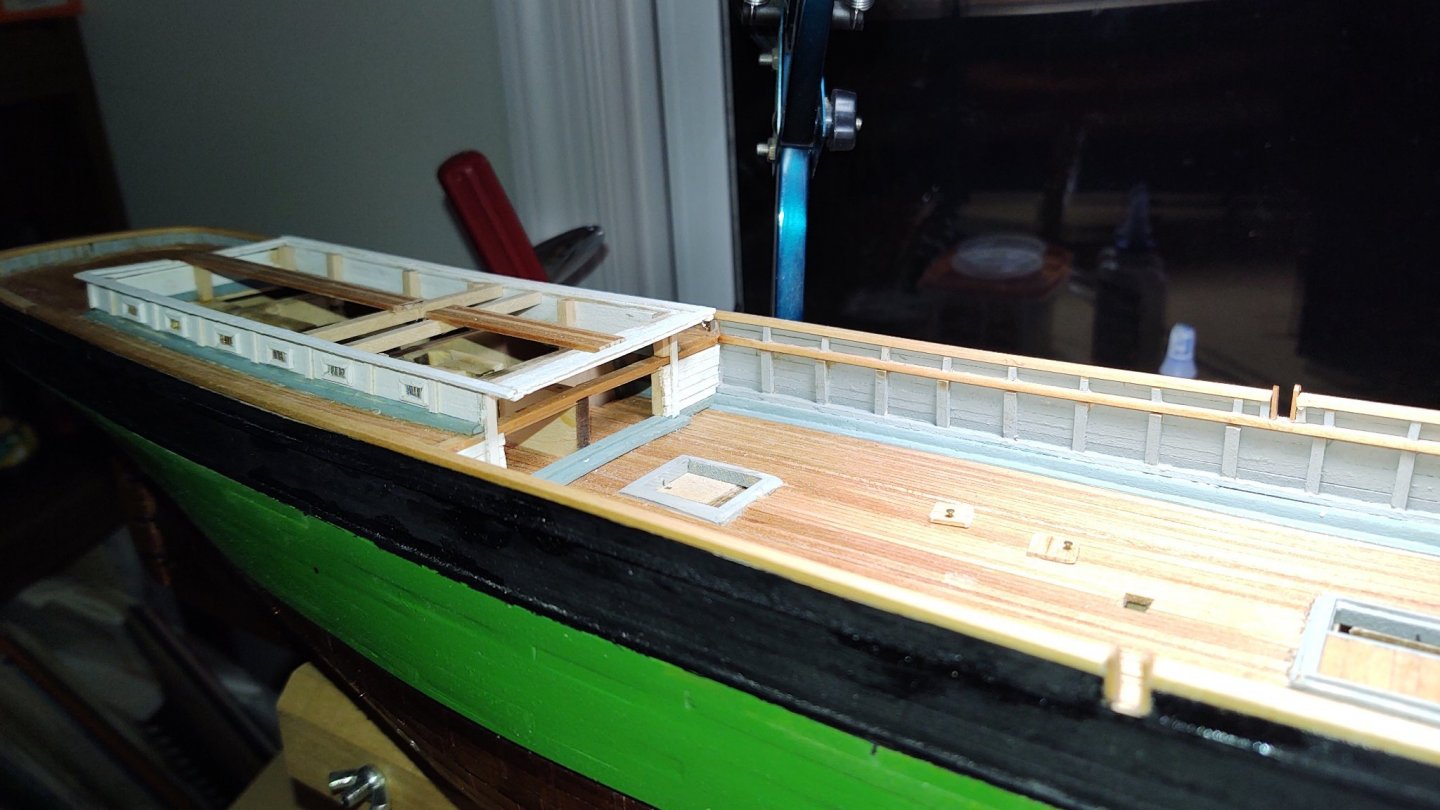
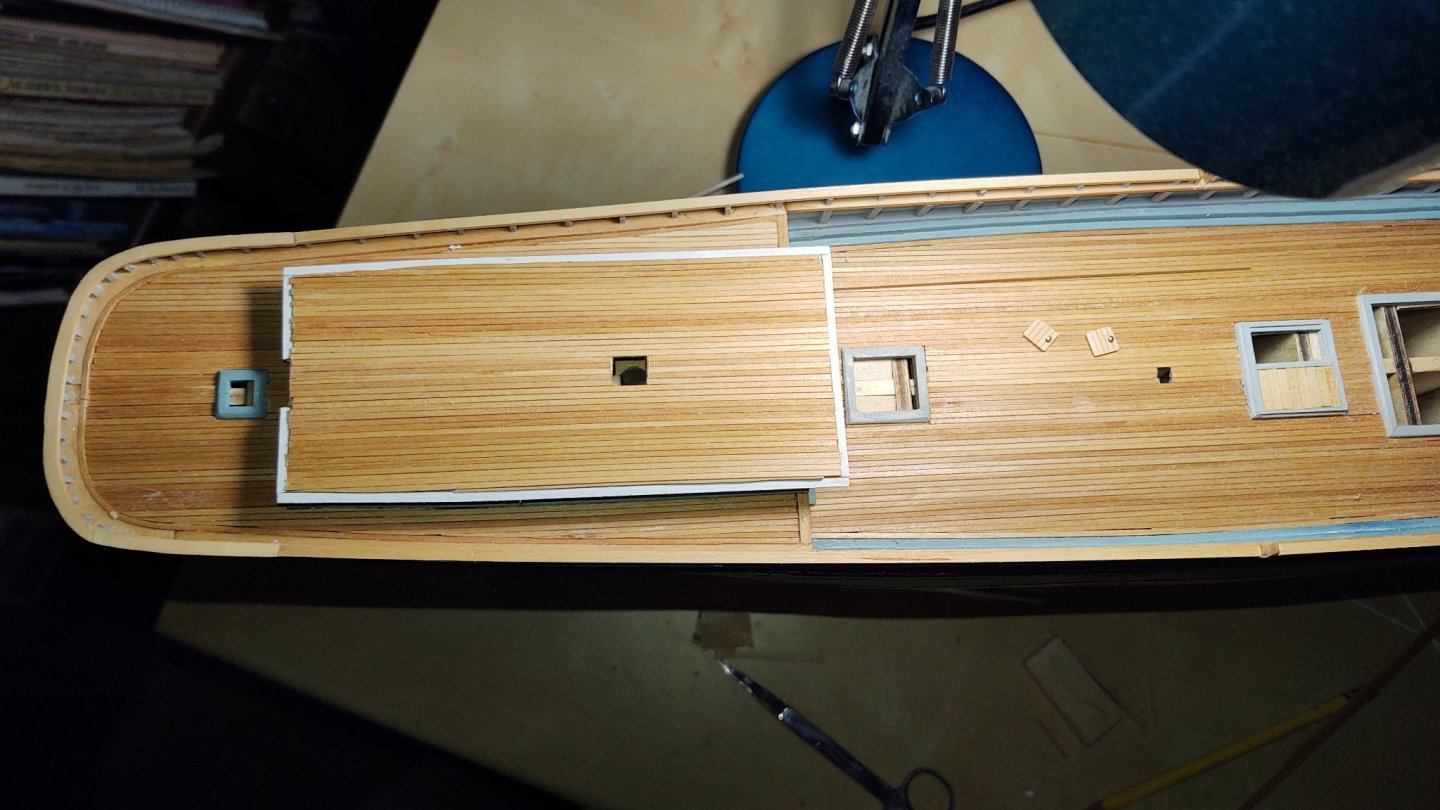
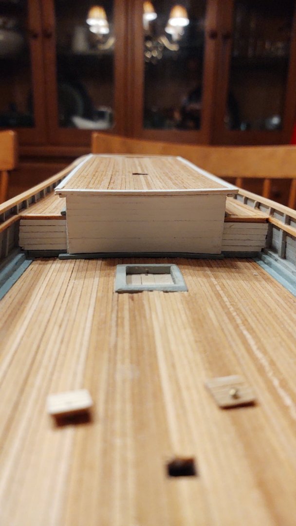
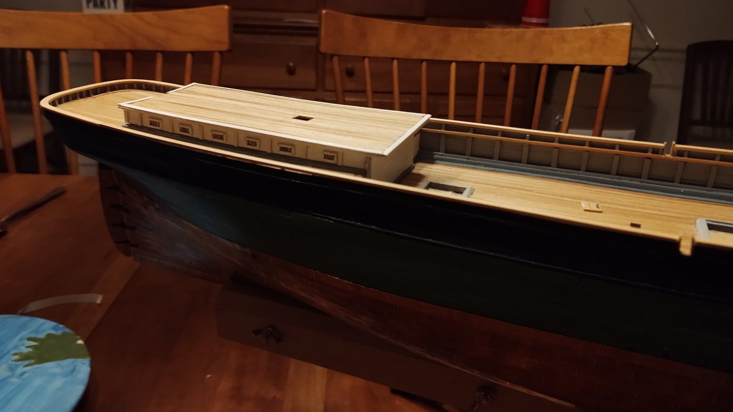
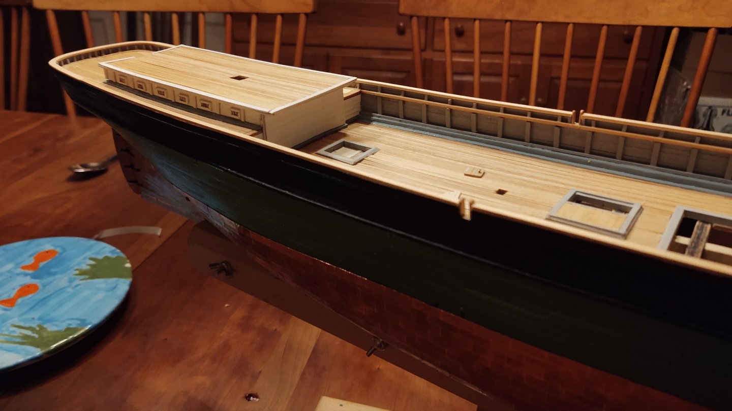
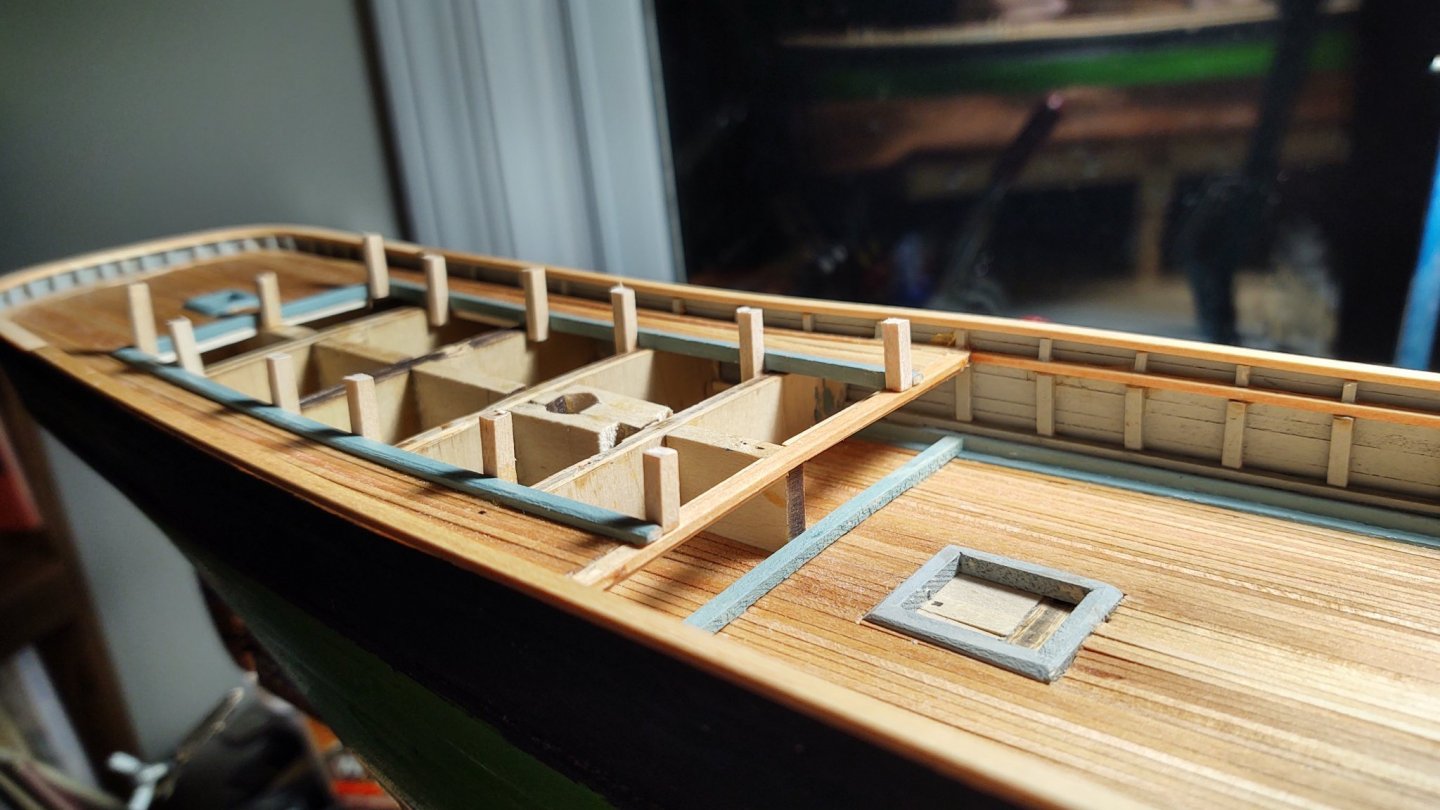
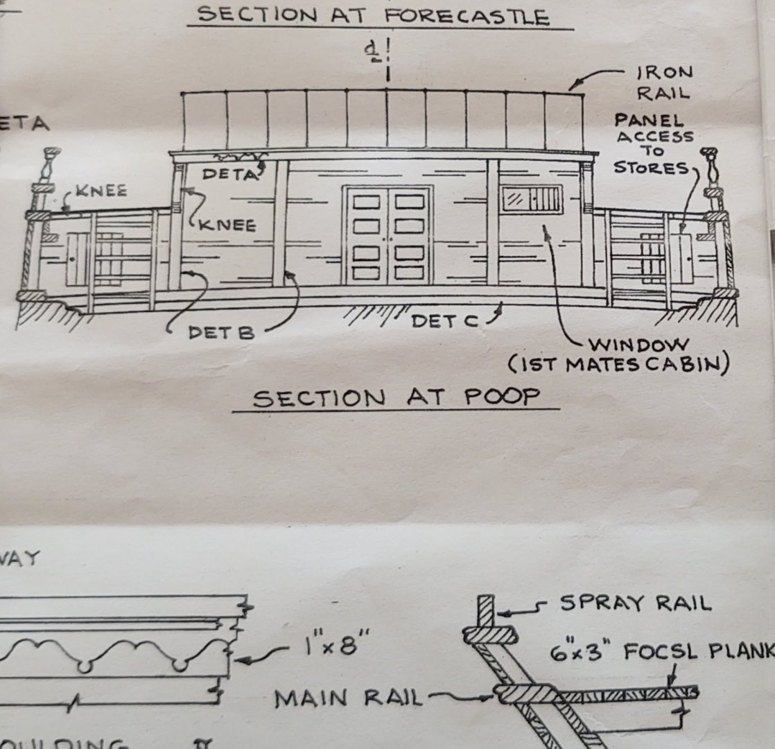
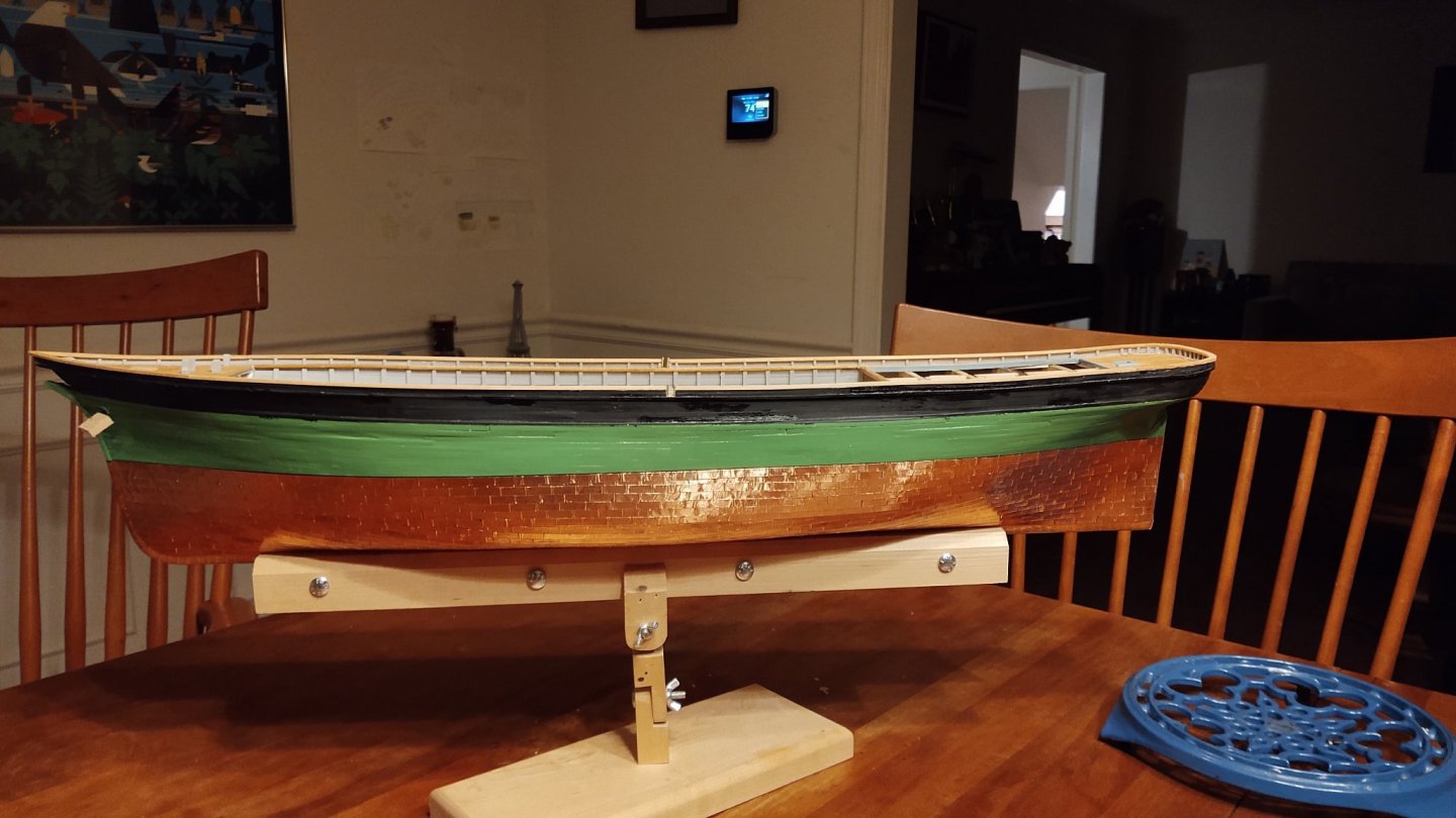
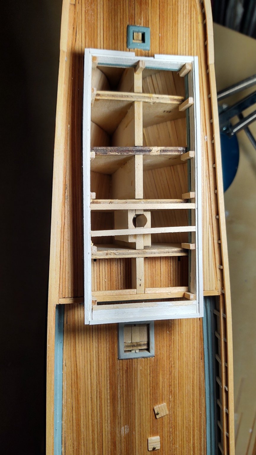
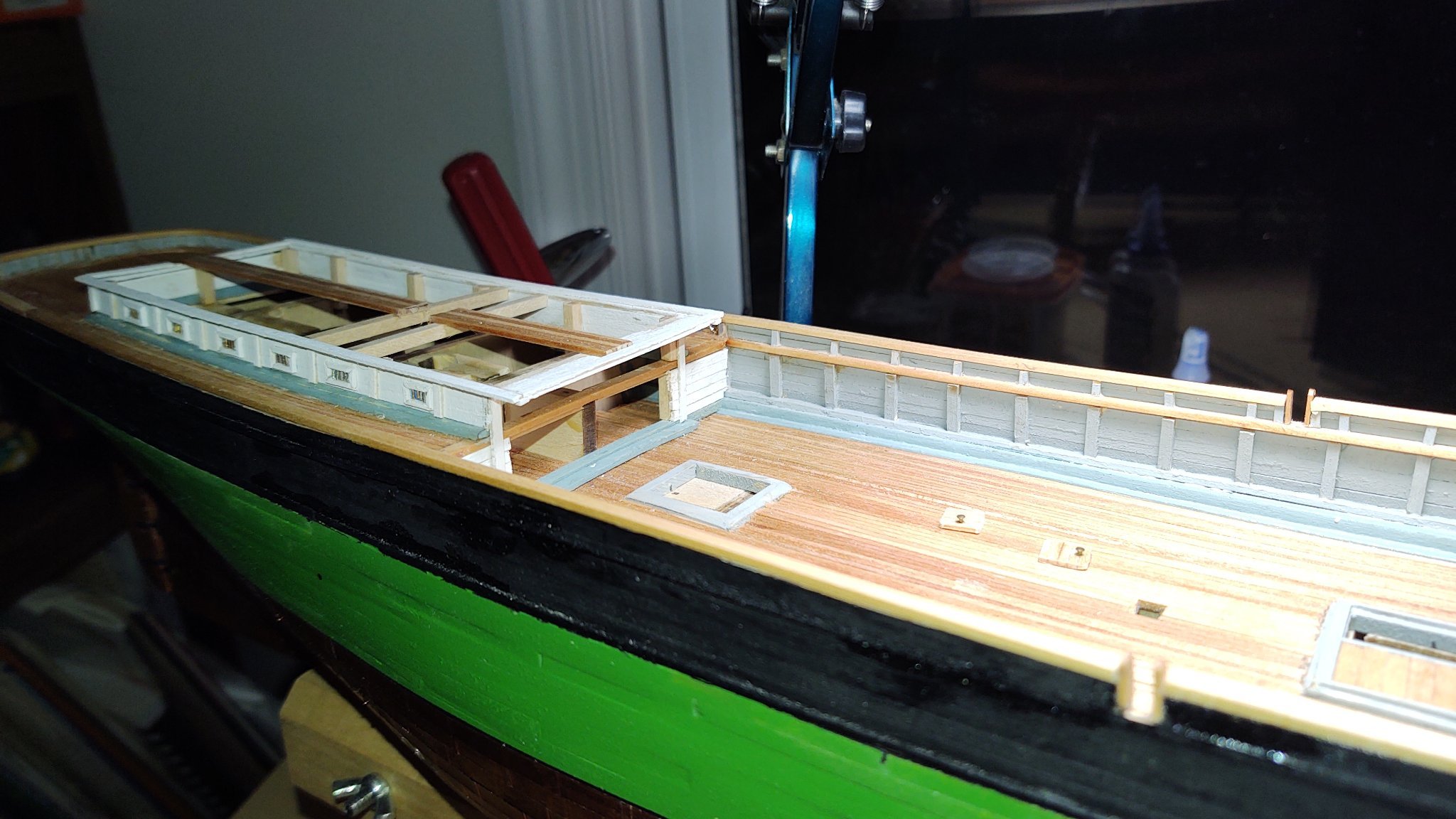
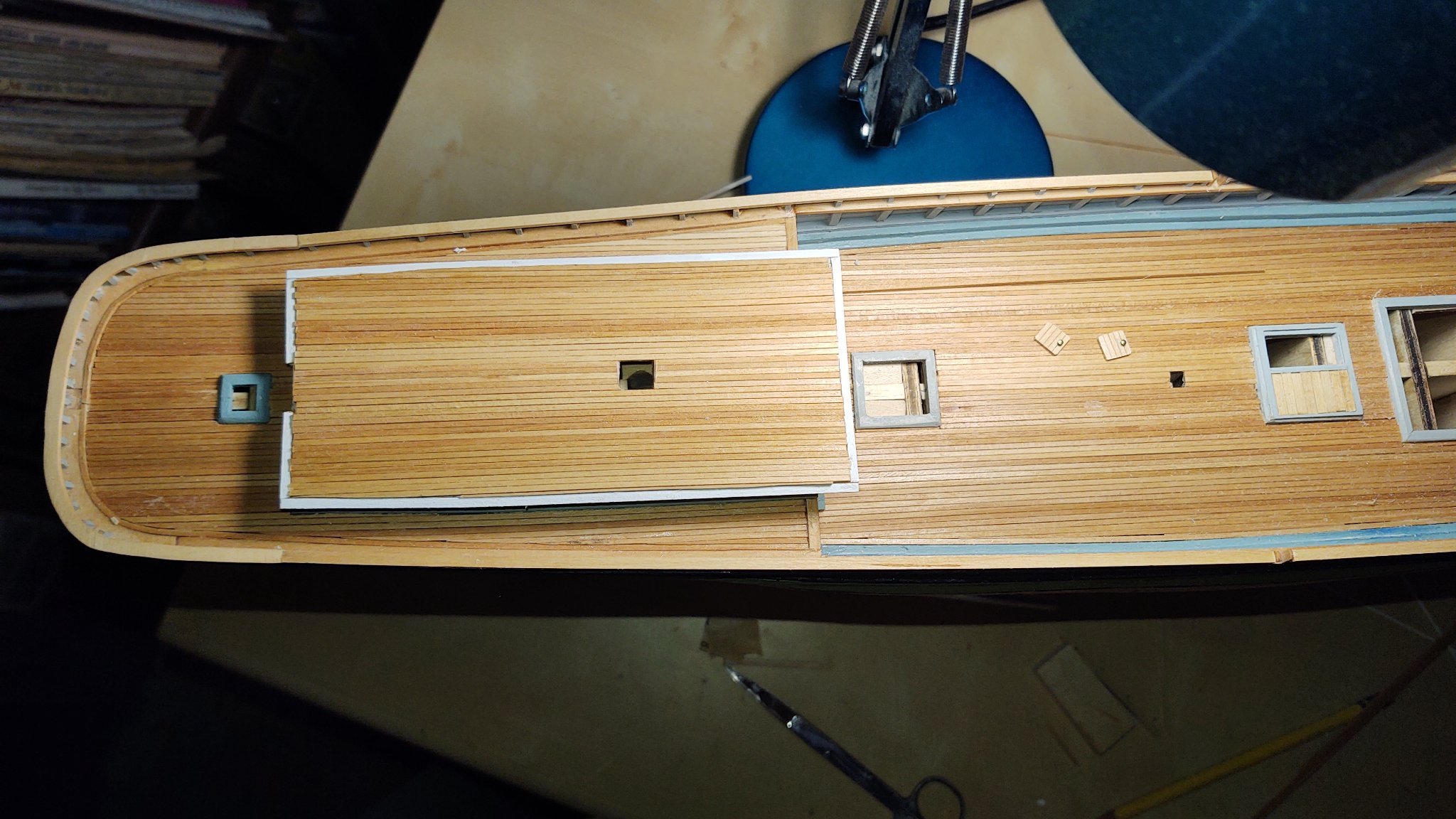
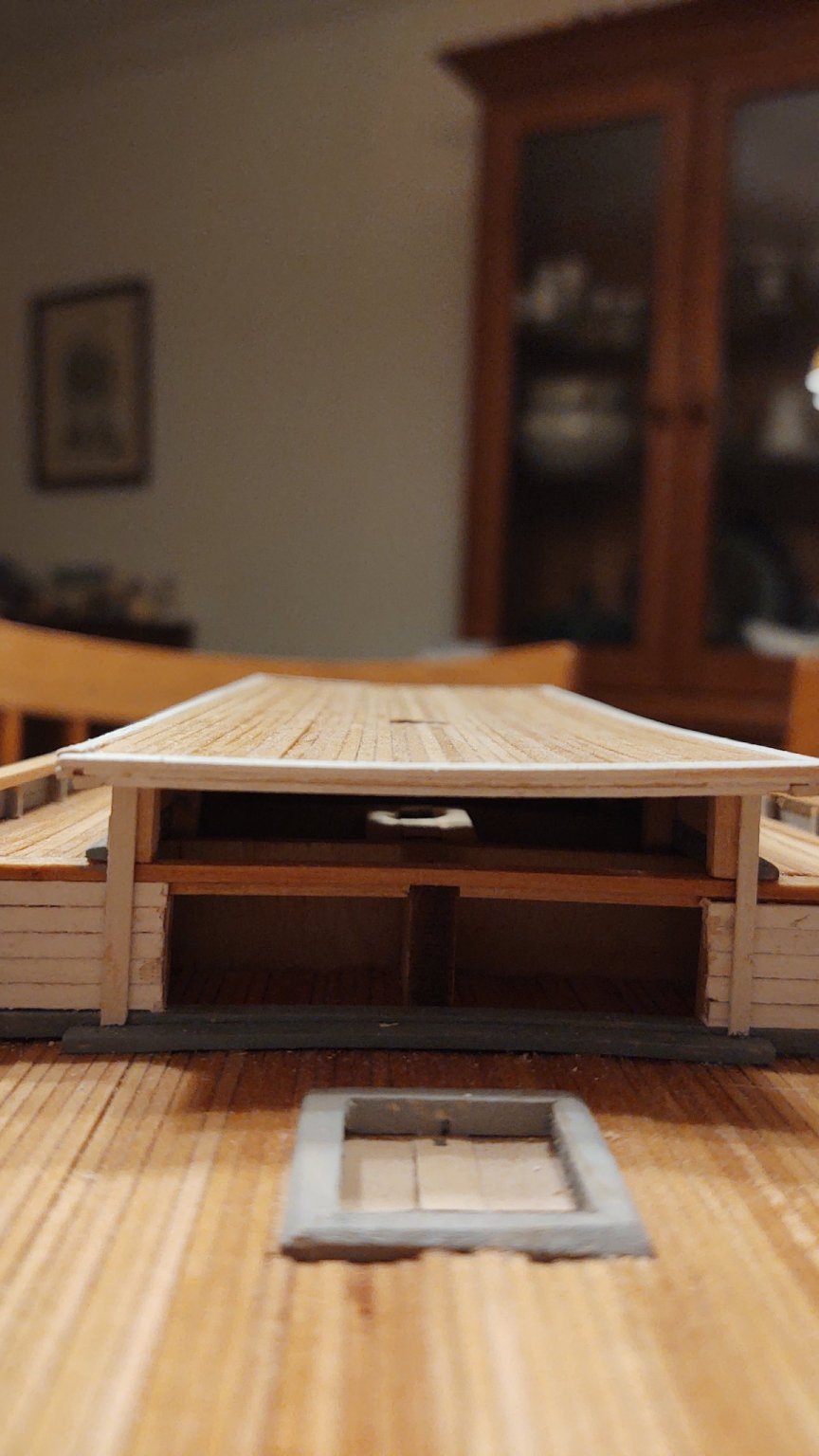
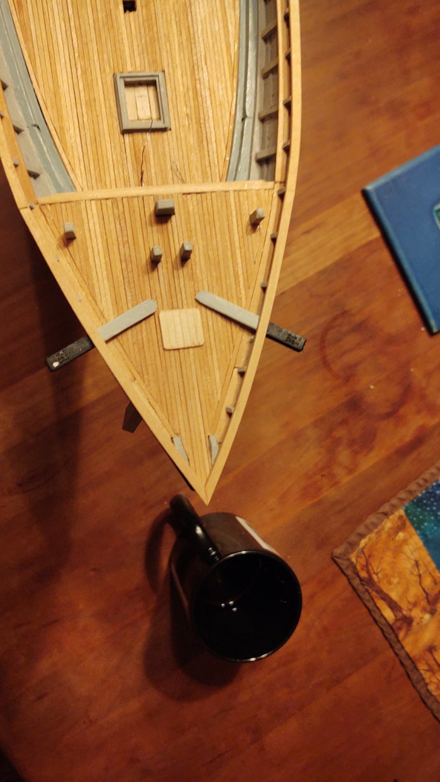
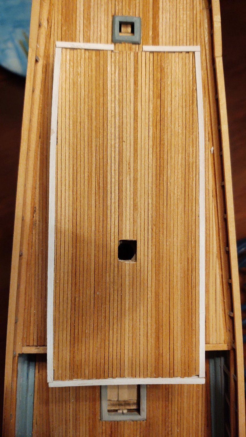
 Progress has been made on the cabin and other parts of the ship. First, I constructed and mounted the catheads: I did put a copper star on each cathead, made out of extra copper tape. It was unbelievable how long it took to cut out a star that small that I could manipulate, but it's done. I still have to make and mount the anchor release, a couple of eyebolts, and there is a drilled hole inboard for a bit of 'iron' wire, but I'll deal with that later. As of my last post I had bulkheads of the poop cabin, and was putting on window frames and bars. That was completed for both sides, and then mounted on the framework I erected on the coaming. I then cut pre-painted wood strips to represent the vertical planks on the bulkheads between the windows and mounted them on the bulkheads, and mounted a another plank that runs the length of the cabin and formed the outer edge of the cabin and the overhang. I took another section of pre-painted and used them to create the bottom of the overhang, which would then be used to mount one end of the deck planks over the poop cabin. I needed to be able to allow the mizzen mast to pass through the deck, while still having something for the deck planking to rest upon in the center section of the ship, so I put two beams in place to ensure that the planks had somewhere to sit. Finally, I put another set of planks around the outer edge to form the boundaries of the deck planks. You can see what I mean in the photo below. One thing I noticed after the fact is that the two beams that are there to provide something for the center planks to sit on are crooked in the horizontal plane. I was more concerned with their alignment in the vertical, and so it looks kind of odd, but didn't have any real impact in the end. The cutout in the stern is for the companionway, and the two small pieces on the deck are going to be the doors to the storage areas that will fit on the forward part, next to the cabin. I then started putting in the deck planks, beginning from the center and working outward so that it would be as symmetrical as possible. I had a bunch of planks from the main deck that were stained at the same time and I resolved to use them. Planking went fairly smoothly: One thing I had not realized was that the deck planks were thicker than I had recalled, so that they stuck out above the white painted edge more than I wanted, so I added another layer of pre-painted edge trim. I have not yet closed out the cabin, as can be seen here: I've built the base of the front of the cabin, but before I install it, I'm going to put the window, the doors and the decorative planks, and then just slide it into place. The two doors from earlier will go in the planked up area on either side of the cabin (as in the diagram below), and then I'll need to make the two knees that support the overhang (and the iron rail, and the skylights, and the companionway, and the rest of the deck furniture, and, and, and...) This is what it looks like slid into place with out the So, here is what the Fish looks like now, with the cabin front slid into place, but without the decorations or being glued. Much still to do. As always, thanks for the likes and looking in! Regards, George K
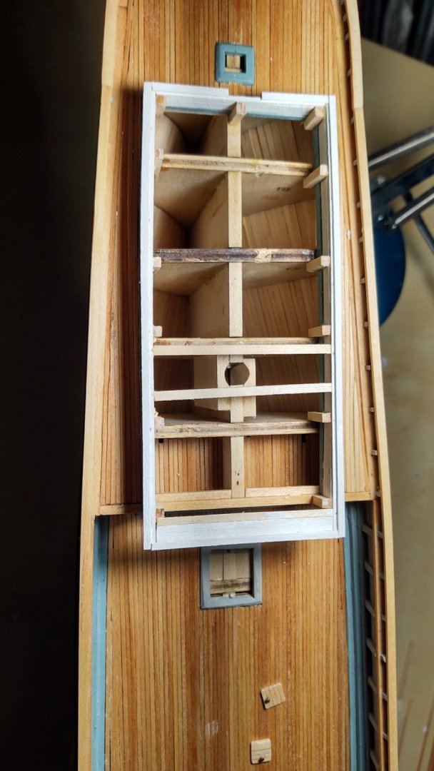


.thumb.jpg.9cfd3d3cdeea7d37c44ed02222f3a891.jpg)
- 602 replies
-
- 8
-

-
- Flying Fish
- Model Shipways
- (and 2 more)
-
Your reconstruction makes sense. My only observation is that any cover that would block a plunging shot would probably be mighty heavy, especially if it's armored. Removing it could be an interesting evolution and putting it back even more so in the absence of a crane. A thin cover might we'll be worse than none because a glancing hit could generate the high speed splinters that did terrible injury on wooden ships. But that's trivia. What an amazing build! You should really see if Vicksburg would display the model, it is that awesome! George K
-
Hi Rob. Are the windows with the two panes and the three wooden sections next to them meant to be sliding shutters? I ask, because the Fish has a 8 of them, but the plans suggest that the sliding shutters are arranged as three vertical slats rather than horizontal. Is that something that varied ship to ship or time to time? Or no one really knows, so do your best? Love the work, looking fabulous!
- 3,560 replies
-
- 1
-
-
- clipper
- hull model
- (and 2 more)
-
I like the idea of the card stock for the detail under the roof. I had looked at metallic tape that was fluted, on the logic that I could paint it and it would self adhere. That may yet be the strategy, check back in a week. And the unique way if building the cabin may yet turn out to be the stupid way 😃. Only one way to find out...
- 602 replies
-
- 3
-
-
- Flying Fish
- Model Shipways
- (and 2 more)
-
Yeah, the wire is 24 guage and so corresponds to 1.9 inches at scale. It's definitely too big. I'd need to go to 36 guage to be the proper size and I'm not convinced they would be visible at that size (it's about 0.1 mm diameter, a fifth of 24 guage). I only put in 5 bars per window which would probably have been a problem on the real ship in terms of providing protection with what I imagine are only about 1/2 inch wide bars on a window that large. However, it gives a nice hint of the detail without being overly intrusive, so it seemed.to make sense. I thought about painting them in with a fine tip paint pen, but the paint pen would have made a wider line, so out with that. George
- 602 replies
-
- 1
-
-
- Flying Fish
- Model Shipways
- (and 2 more)
-
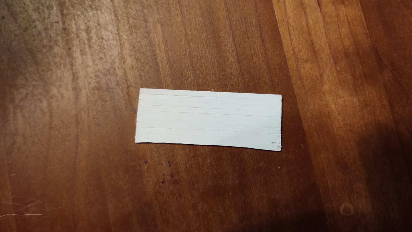
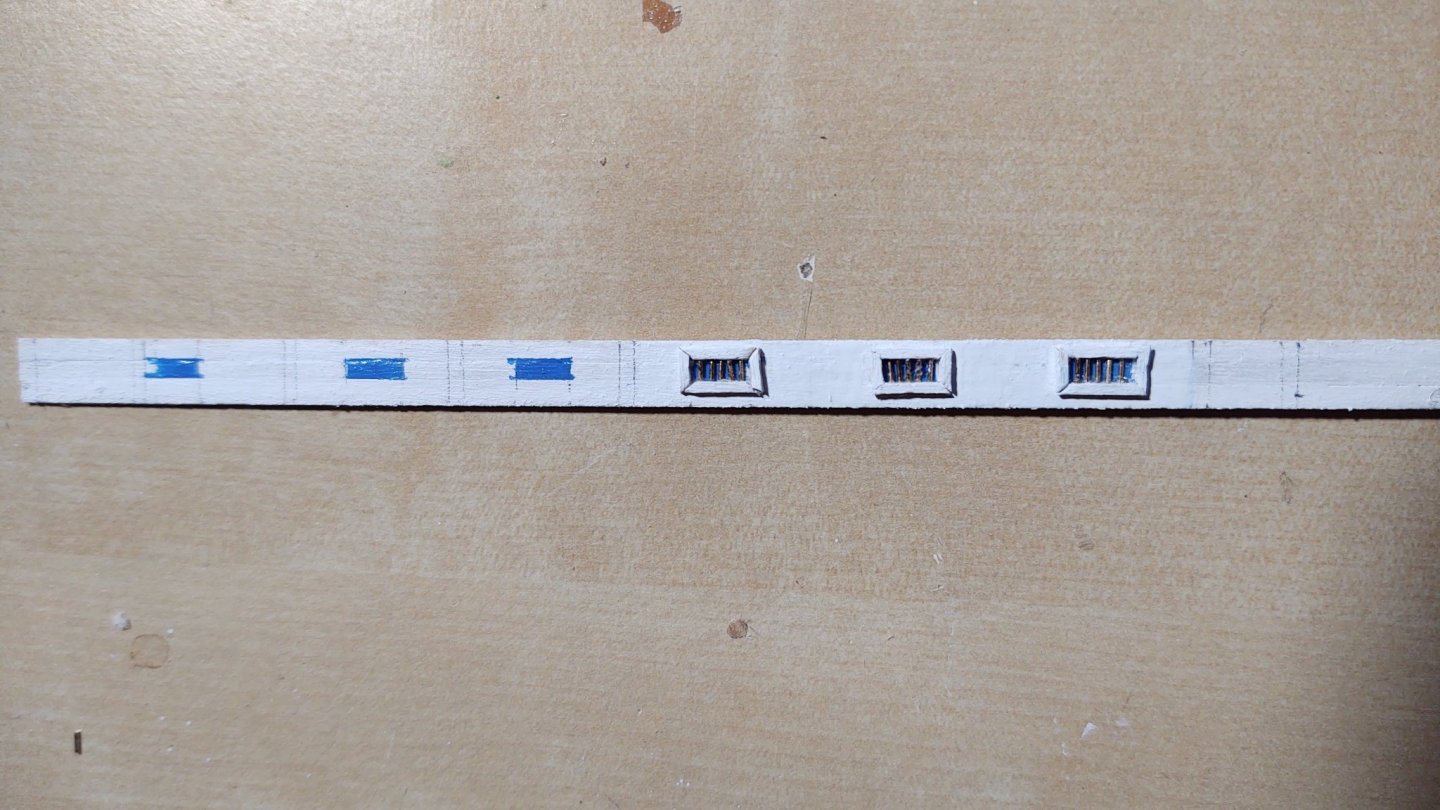
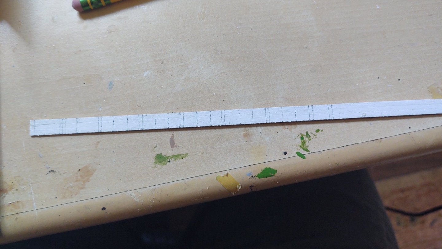
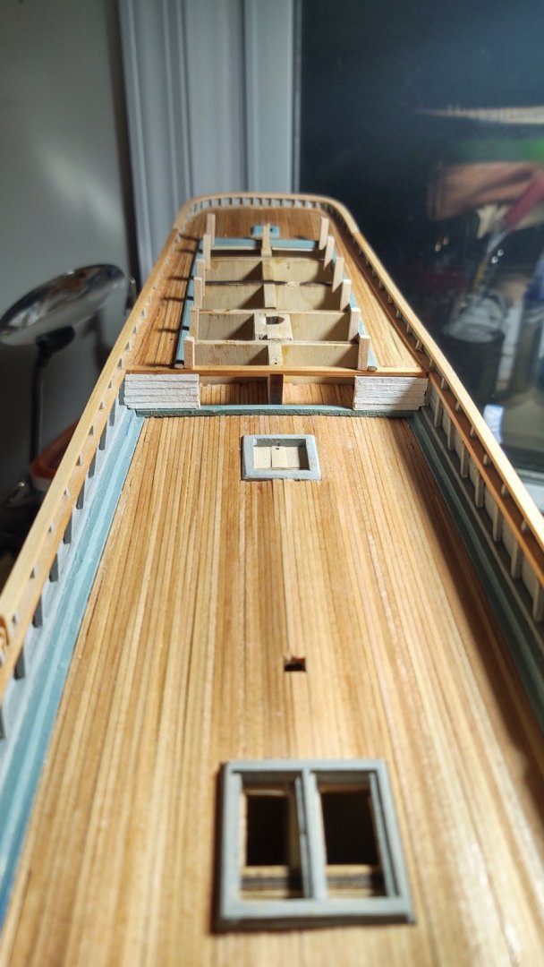
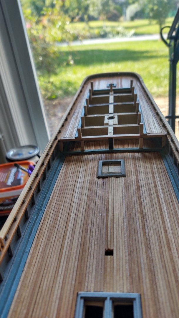
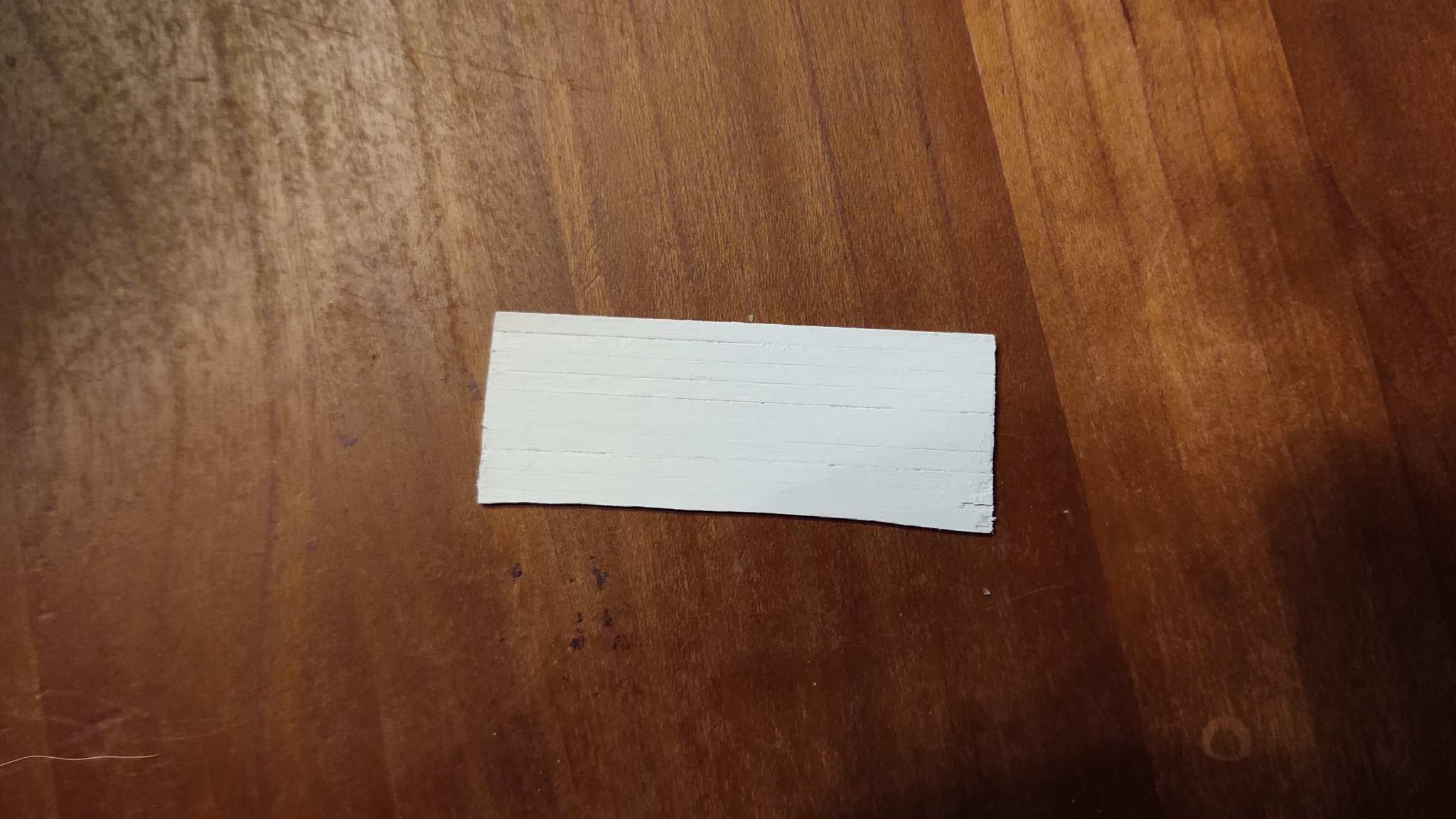
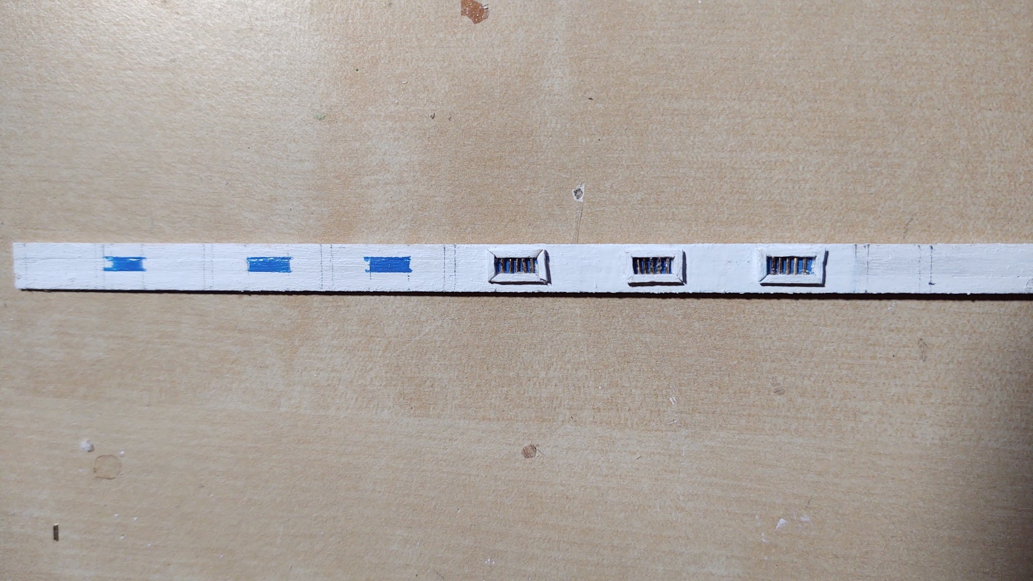
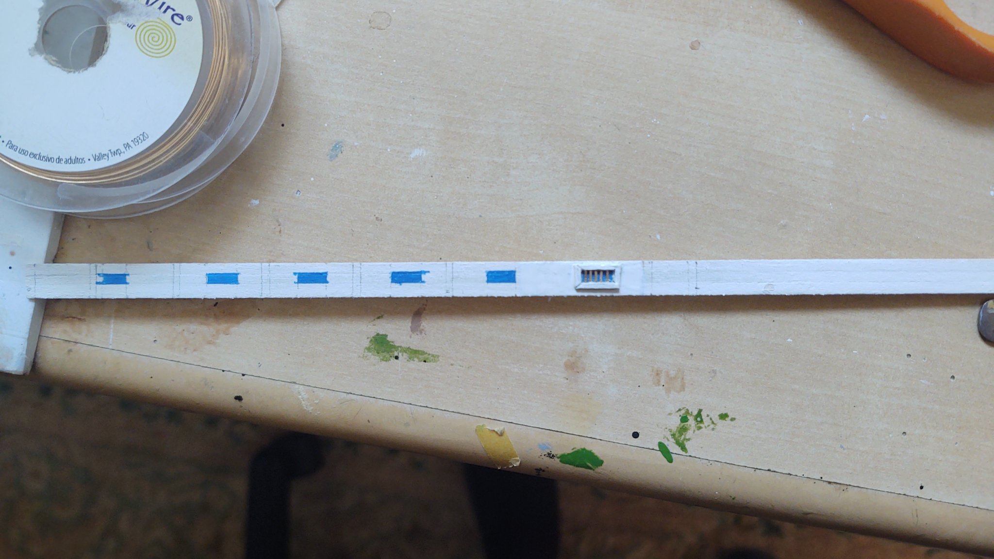
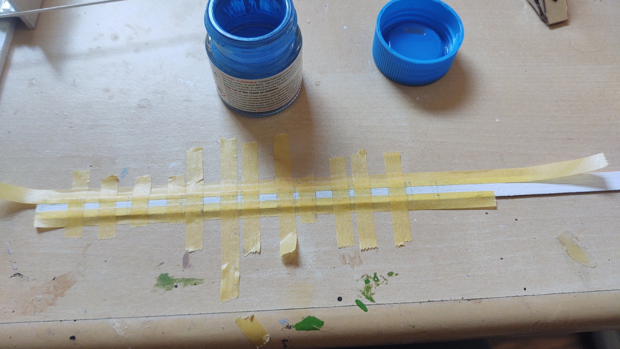
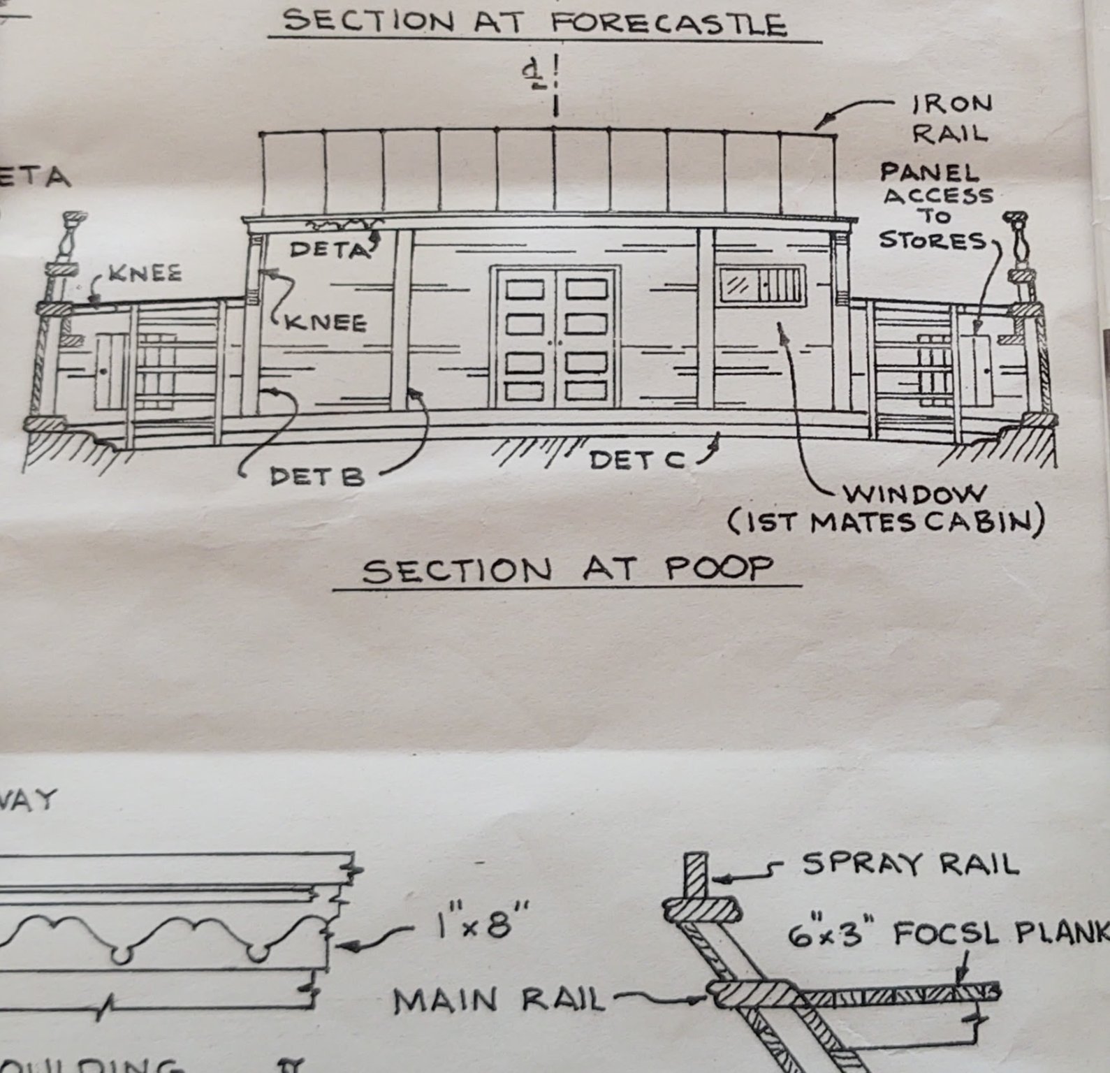
Just a bit of an update. I've started constructing the after deck house. Rather than building it separately and mounting it on the coaming, I'm going to build the house in situ. There are two reasons for this. First, the house (and hence the coaming) is not straight, but rather narrows toward the stern in a curve that I bent into the coamings - so, putting it together separately would be difficult. The second issue is dealing with the overhang that I've mentioned before. So, build on site it is. Step 1 is to install the main deck coaming and then to install a set of, for lack of a better term, stanchions that define the boundaries of the coaming and hence the house. In addition, I added 4 uprights between the main deck and the poop to provide a place to mount the planks that will define the bulkheads that run only from the main deck coaming to the poop deck. Two are mounted directly against the bulwarks, and two are just amidship of each fo the poop deck coamings, as the higher segment matches up with the coaming on the poop (photo of the uprights and then a segment of the plans that describe what I mean). So, the planks were pre-painted white and then installed as below: Now, the main part of the deckhouse (the part that will be mounted on the other uprights) is relatively low, and has a set of 6 windows with bars on the port and starboard sides: This is about 3 1/16 planks wide, so I made a set 3 wide, and then overlaid them on the plans, marking them for the vertical details and the location of the windows: Now mask away: And paint blue where the windows will sit. I then used 1/32 square planking (pre-painted white) to make a window frame, and then embedded brass wire to make the window bars. Here's the first one: And now three: Once finished, I will mount on the coaming, add the vertical details, and then slice off any remaining upright with a dremel cutting blade. Then the deckhouse will be topped off with a 1/16 square plank that will be flush with the vertical detail planks, and we can move to the central section that runs from the main deck. In order to make it look right, I think I'm going to have to add another coaming section on the main deck so that the bulkhead planks have something to land on (there is no room going straight down, but that should not be a huge problem. Thanks again for looking in and the likes! Regards, George K


.thumb.jpg.238a921a25b54fc9fa69e2f8db438a9d.jpg)
- 602 replies
-
- 9
-
-
- Flying Fish
- Model Shipways
- (and 2 more)
-
They are indeed beautiful ships. It would be great to see a real one, I've seen the Cutty Sark and the Star of India, but they are later and hybrid or iron construction, so not quite the same thing....
-
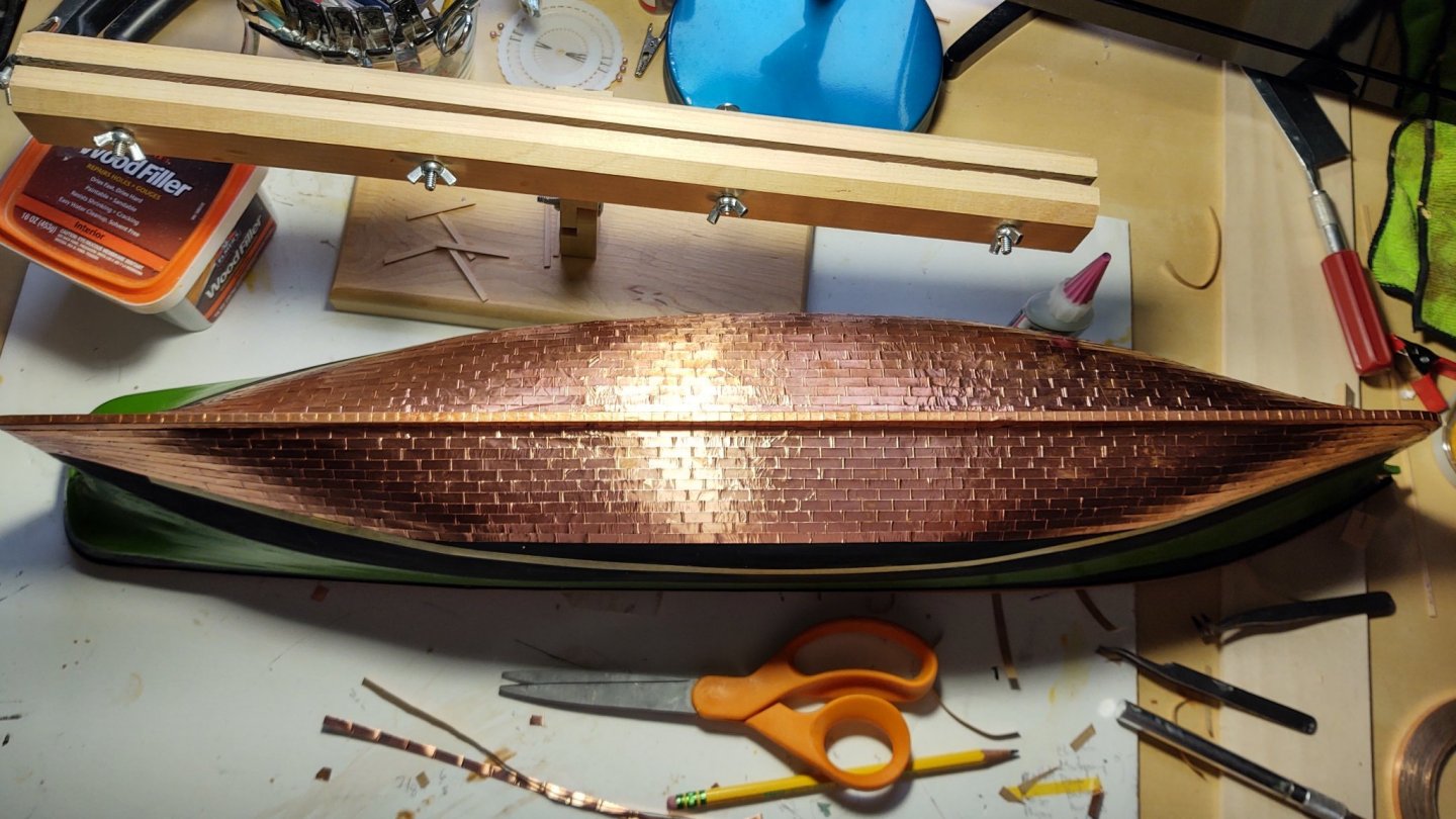
Cooper looks great. Did you do that one plate at a time?!
-
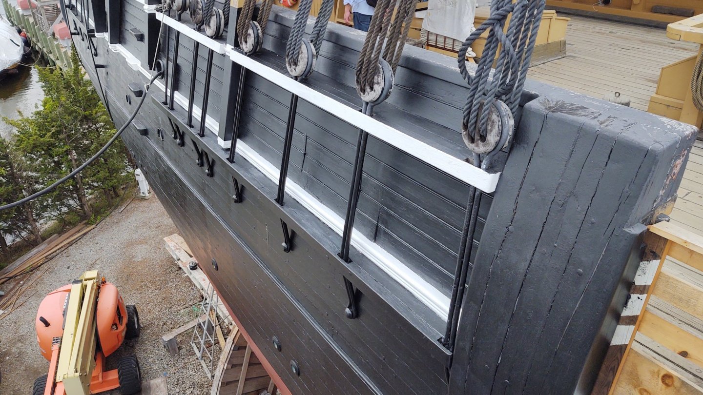
I was looking at the construction of the chain plates (which appear to be similar to the ones on the Charles W Morgan (i.e. they are functionally a loop of iron pressed together in a long thin shape) -useful information as I'm considering building them that way. However, I don't see any deadeyes on the shrouds or the chain plates, unless they've been served over. Would anyone have served over the deadeyes and the lanyards?

- 602 replies
-
- 1
-
-
- Flying Fish
- Model Shipways
- (and 2 more)
-
That makes sense. There must be at least four variants, as the plans I have (all amazing and all by Ben Lankford) are comprised of 6 sheets; four (including the sheet with the deck plans) are labelled 1979, revised 1982, and two are labelled 1993. The latter are the POB construction sheets, and I presume they were replaced/added when the Fish kit switched from solid hull to POB. I'll try the NRG and see what is there. Plenty I can do elsewhere on the ship while I figure this out
-
That is good to know as it comports with both my interpretation of the plans, and with the way I built the coamings for the house (the bend is subtle but is there).
-
Pretty awesome....
-
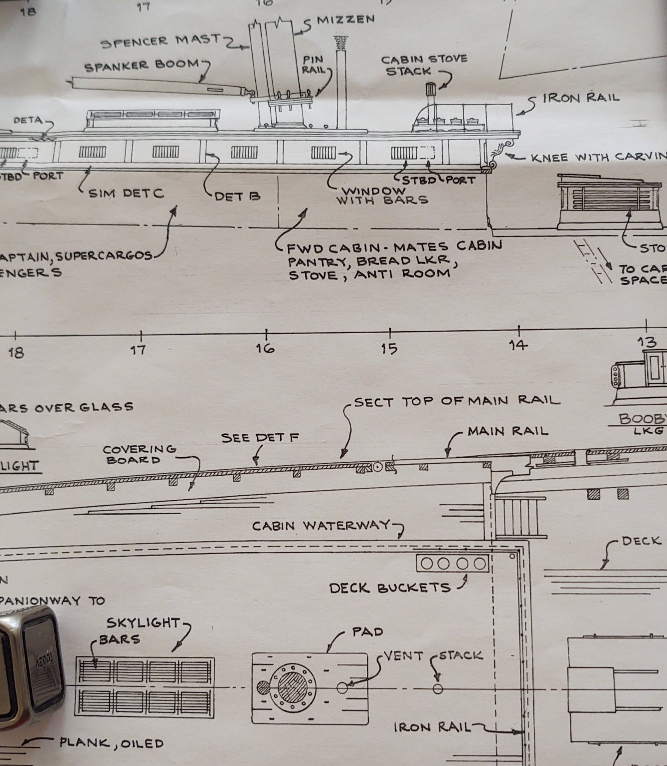
So - a quick question to all you experts on McKay clippers, seeing as I am really having a bit of trouble converting the plans into a constructed structure on the poop. Below are two segments of the Fish's plans. The first shows the poop looking aft, the second shows side and above views of the transition from the poop to the main deck. Okay - so what I do know - the overhead of the poop cabin extends over the main deck, where it has some decorative elements including an elaborate knee. So far so good. Where I am confused is this. If you look at the aft facing view, you can split the area into three segments, two half height sections toward the bulwarks and a center section that is full height. If I read the set of diagrams, it would indicate that the half height segments are built up from the coaming to the edge plank on the poop, with the edge plank overhanging the bulkheads that make up those half height sections (i.e. from aft to forward, you have the forward side of the bulkhead and then the forward side of the poop edge plank. The center, full height section appears to sit completely forward of the edge plank on the poop, which suggests that it is pushed out slightly compared to two half height sections. And it may require a wider coaming at the center than at the edges (need to see exactly where the coaming sits when I install it). Is that correct? That seems to be the configuration that is on Rob's @rwiederrich Glory of the Seas, and it seems to be a McKay feature, but thought I would put the question out to anyone that has build the Fish or done research on McKay clippers (e.g. @ClipperFan or @Vladimir_Wairoa). Thanks in advance, George K.


- 602 replies
-
- 1
-
-
- Flying Fish
- Model Shipways
- (and 2 more)
-
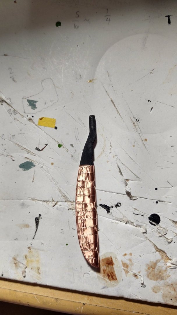
Just a brief update (it's been a crazy couple of weeks without much time to build). Rudder removed, shaped, sanded and coppered: 5 hinges made and rudder attached to hull: The gap between the rudder and the hull is a bit more than I would prefer, but it was a tradeoff between having some detail in the hinges and having the rudder closer (I can't seem to make hinges that are much less thick). So, yes on the detail, let the chips fall where they may. Thanks for looking in! Regards, George K

- 602 replies
-
- 4
-
-
- Flying Fish
- Model Shipways
- (and 2 more)
-
Thank you. And definitely going to let it patina. Not the least of which because it will disguise the obvious fact that it isn't the color of Muntz metal. I thought about the spray paint option, but chickened out.
- 602 replies
-
- 1
-
-
- Flying Fish
- Model Shipways
- (and 2 more)
-
Thank you and I appreciate the insight into the original version! If you are ever in Portland, it's worth stopping at Powell's books, as they frequently have wonderful used editions of books on sailing ships. Last time I was there (my younger daughter was in college in Portland until she transferred last year) I came this close to buying a copy of a three volume history of clippers published around 1920. Still not sure why I didn't, but water under the bridge as it were. FWIW, I am the antithesis of an artist, which is why I enjoy looking at so many of the builds on this site. I remain in awe of the people that can create such beautiful effects with paint or other drawing material, and I find it a useful inspiration, something to swing for, even if I don't reach those standards. At least they focus me to strive for my best. Warm regards, George K
- 602 replies
-
- 1
-
-
- Flying Fish
- Model Shipways
- (and 2 more)
-
The Dover edition that I picked up at Mystic (which is listed as an unabridged version of the 1928 text) is renamed for reasons that I don't understand. It has the diagrams and paintings, but at significantly reduced size and resolution, and only 4 of the illustrations are reproduced in color (2 each on the inside front and back covers). It's a nice start and has a lot of useful descriptive information. George K
-
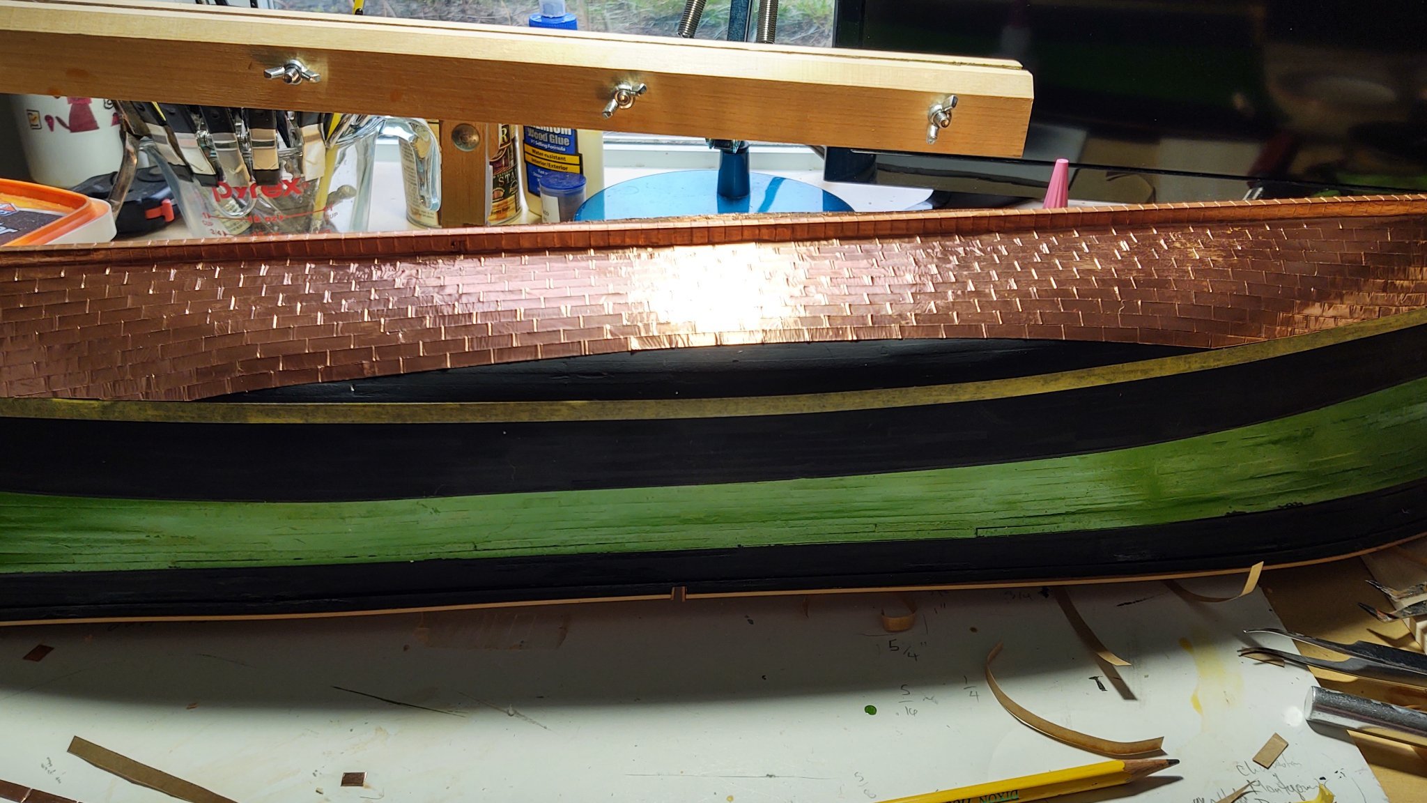
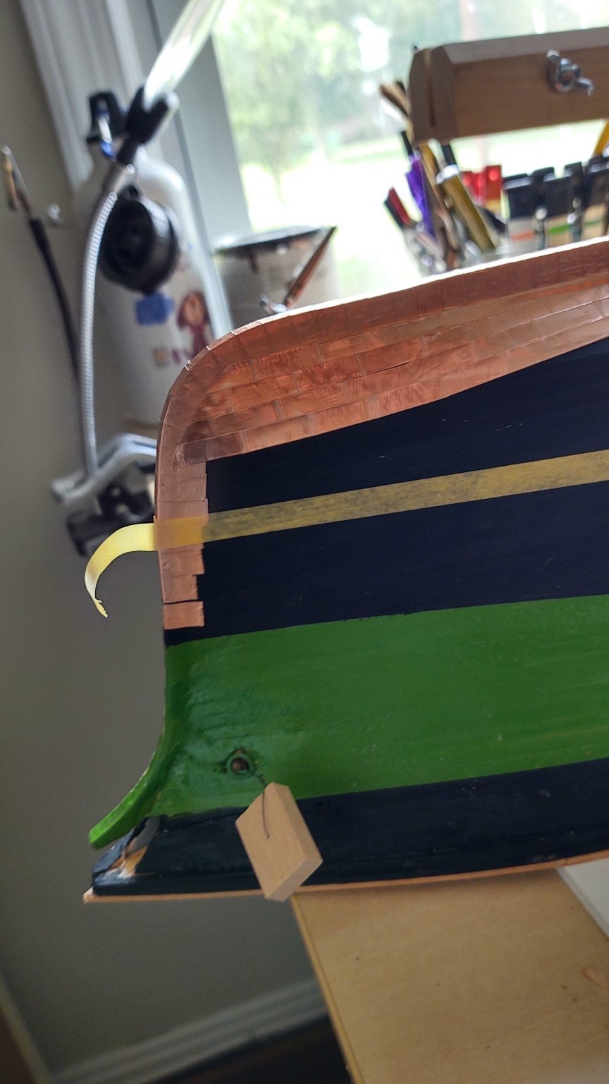
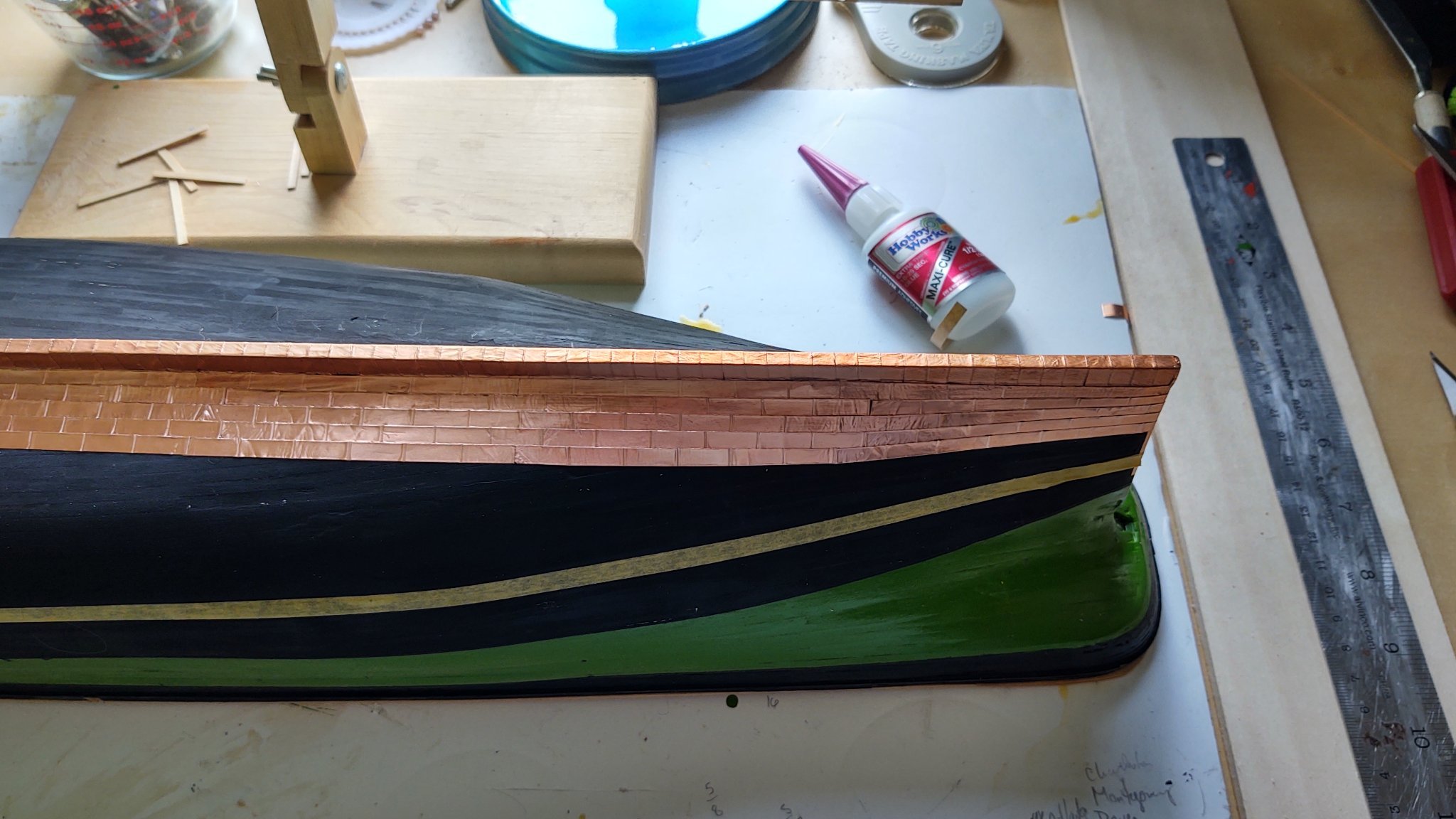
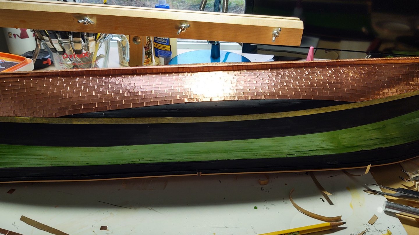
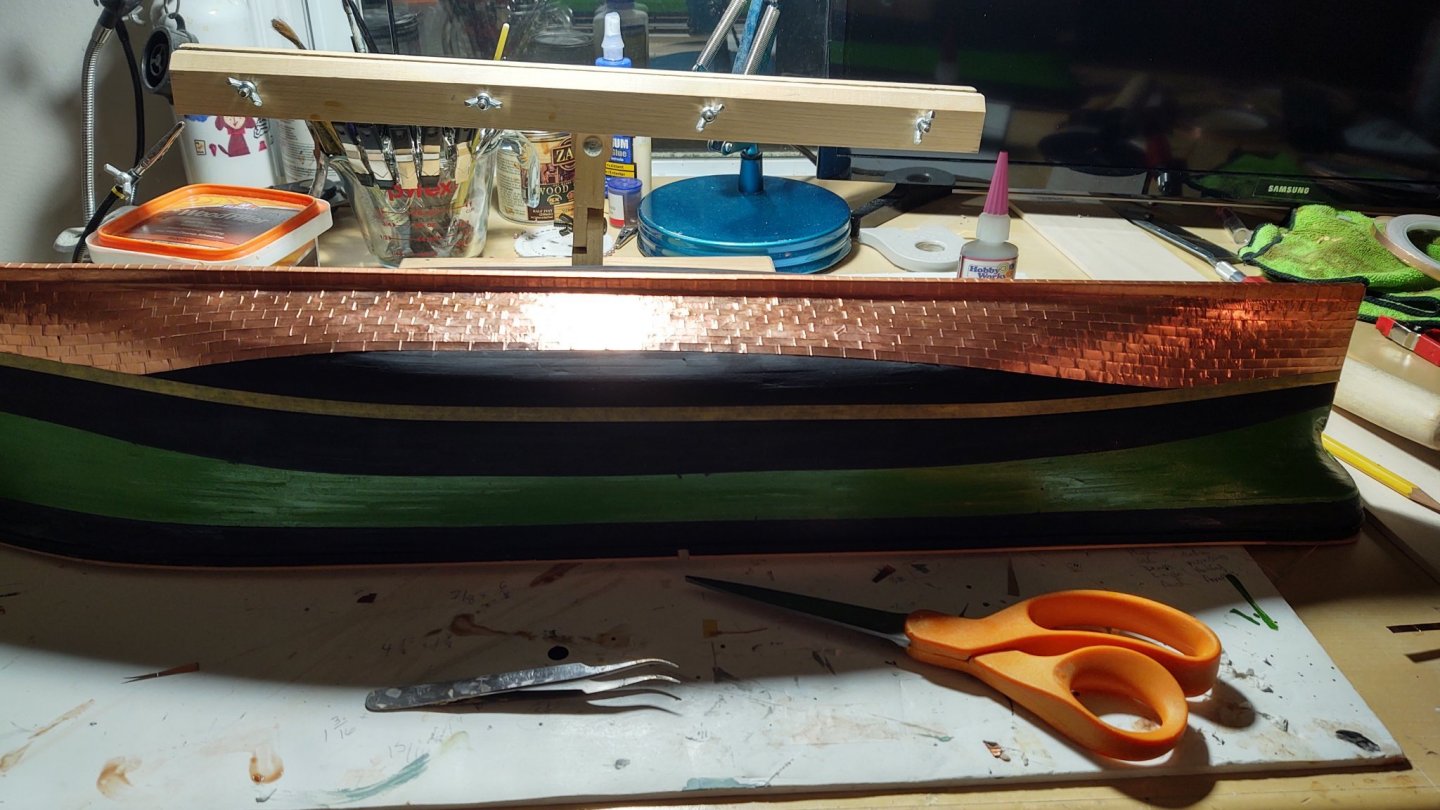
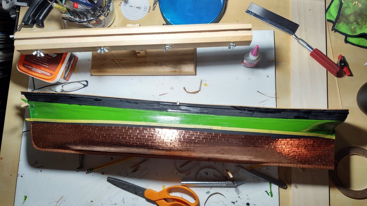
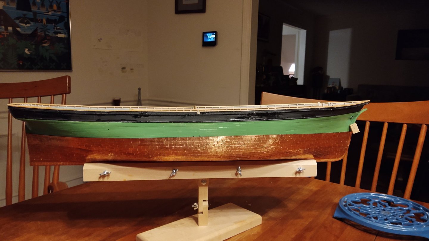
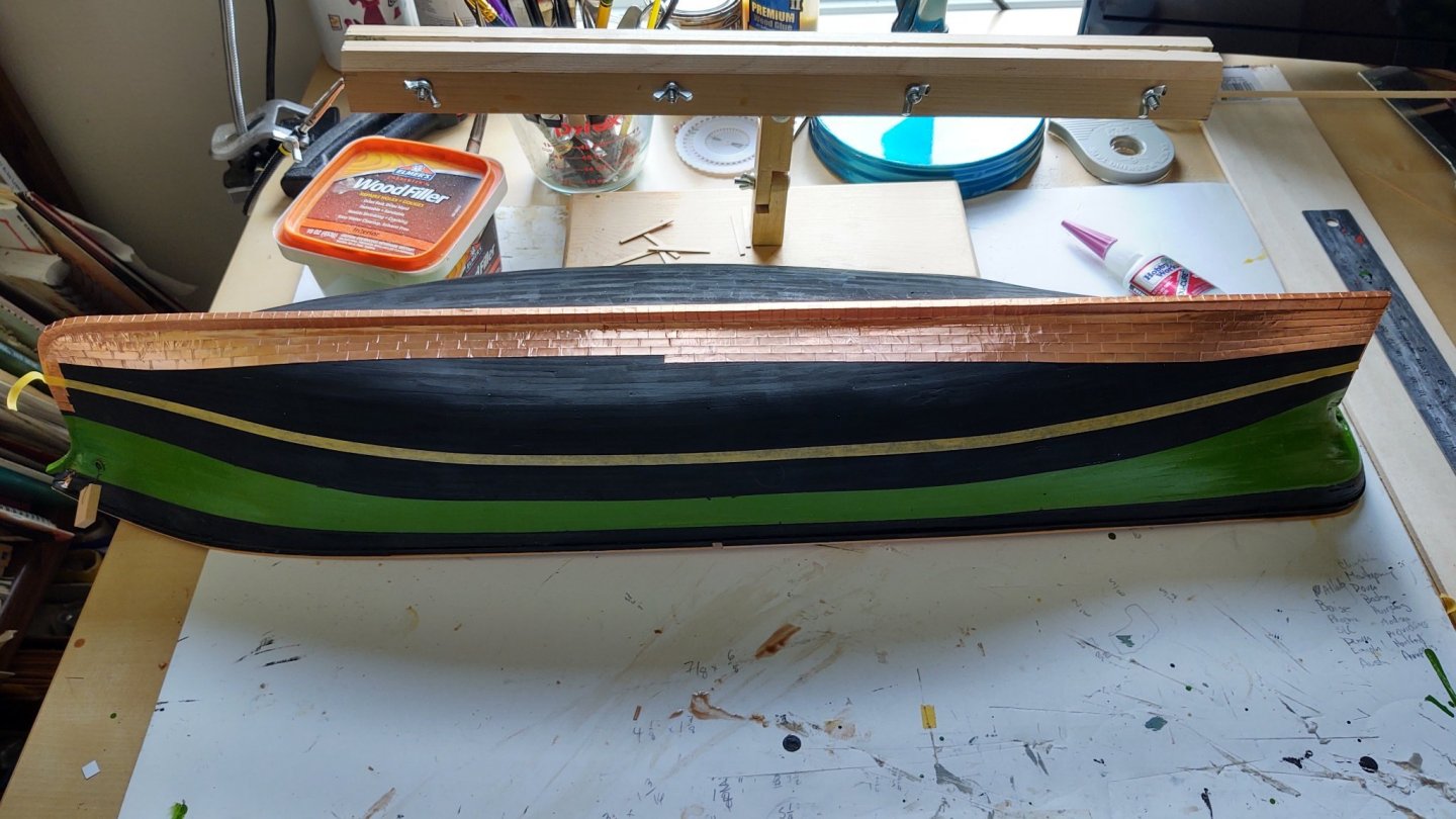
Coppering is complete. These first two photos show how I used the tape on the gore line to define the point where to stop the copper so that the next row above the gore line will sit neatly. And here is a view from above showing the starboard side mostly completed and the port side approaching the gore line. Once the second band of plates was begun, I put another line of tape on the ship with the tape centered over the load water line. It was there so I could copper up to the tape, have decent overlap, and still have a small amount of the black paint showing when I put the cap row into place. Finally, two views of the coppered hull, port and starboard. I used the kit supplied tape to cover the keel, figuring that the extra width wasn't a major issue, and used narrower (3/16"), black backed Venture tape that I got from a stained glass supply store for everything else as it was much closer to scale. The Venture tape is much better tape than the kit supplied tape. If I do another MSW kit, I'm throwing out the kit supplied tape as soon as I open it up. Next steps will be the rudder (so I can be done with copper), and the coamings that support the after deck house on the main deck (the only ones that I didn't install prior to planking). As always, thanks for looking in and the likes! Special thanks to Rob for his method which I adjusted to fit my needs. George K.
- 602 replies
-
- 8
-

-
-
- Flying Fish
- Model Shipways
- (and 2 more)
-
Good to get the right name. The term I used came off the Model Shipways plans for the Constitution
-
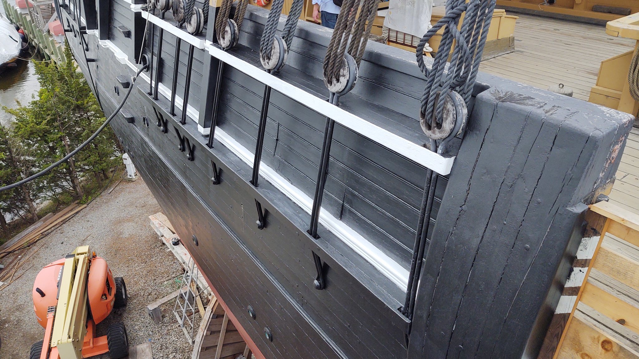
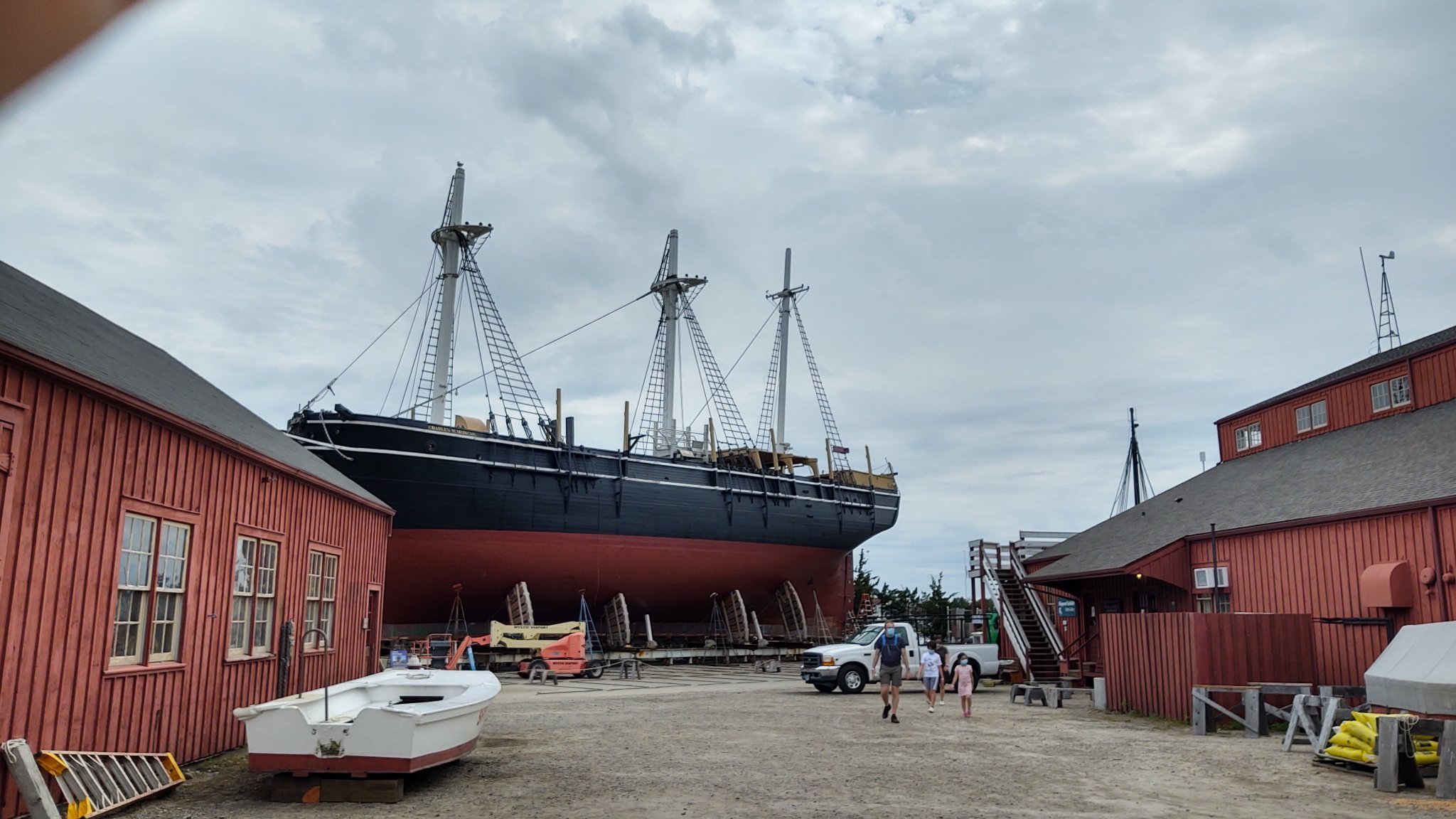
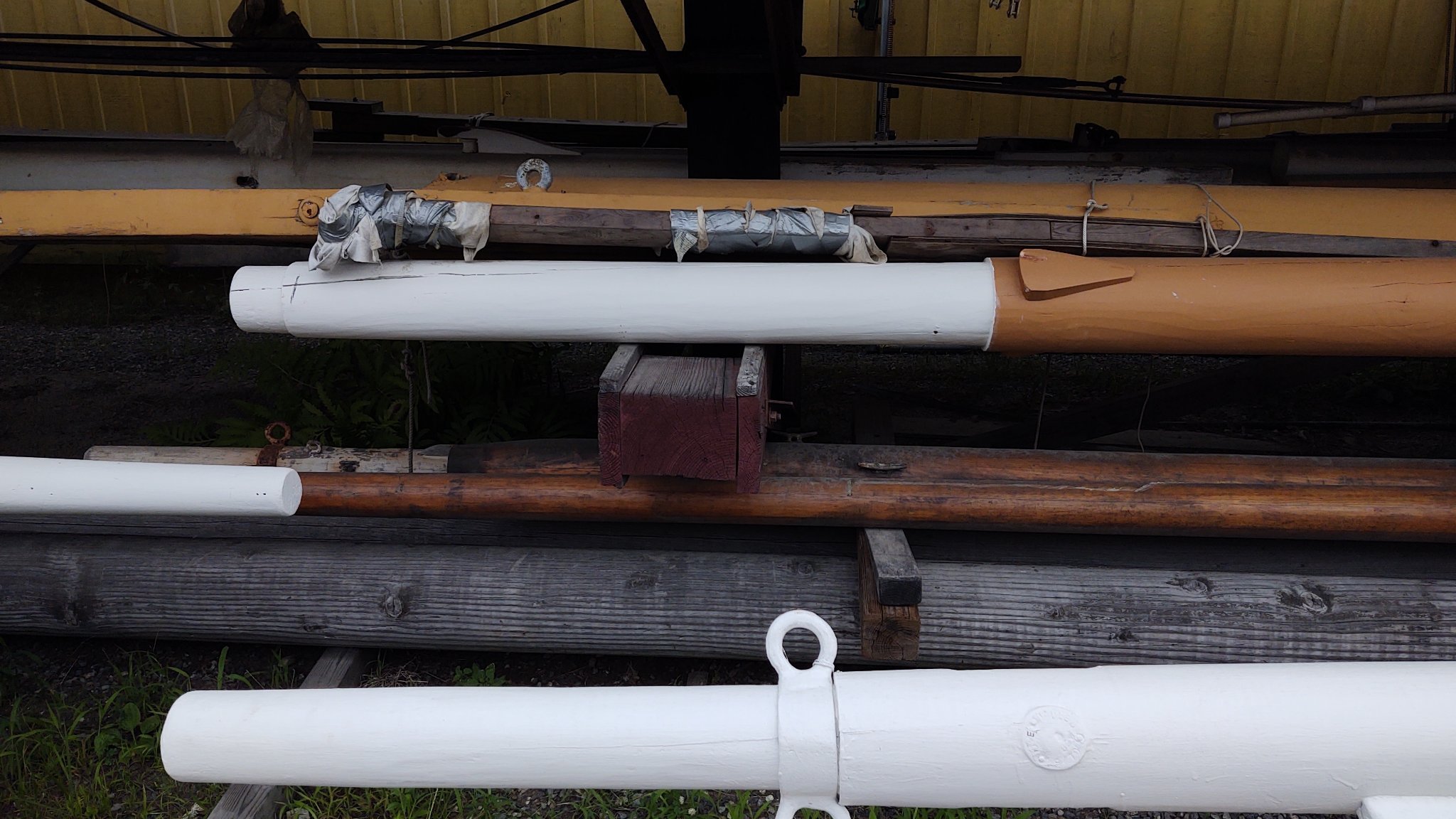
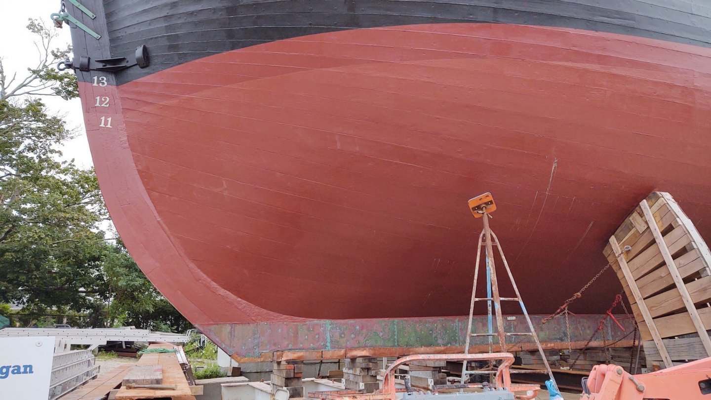
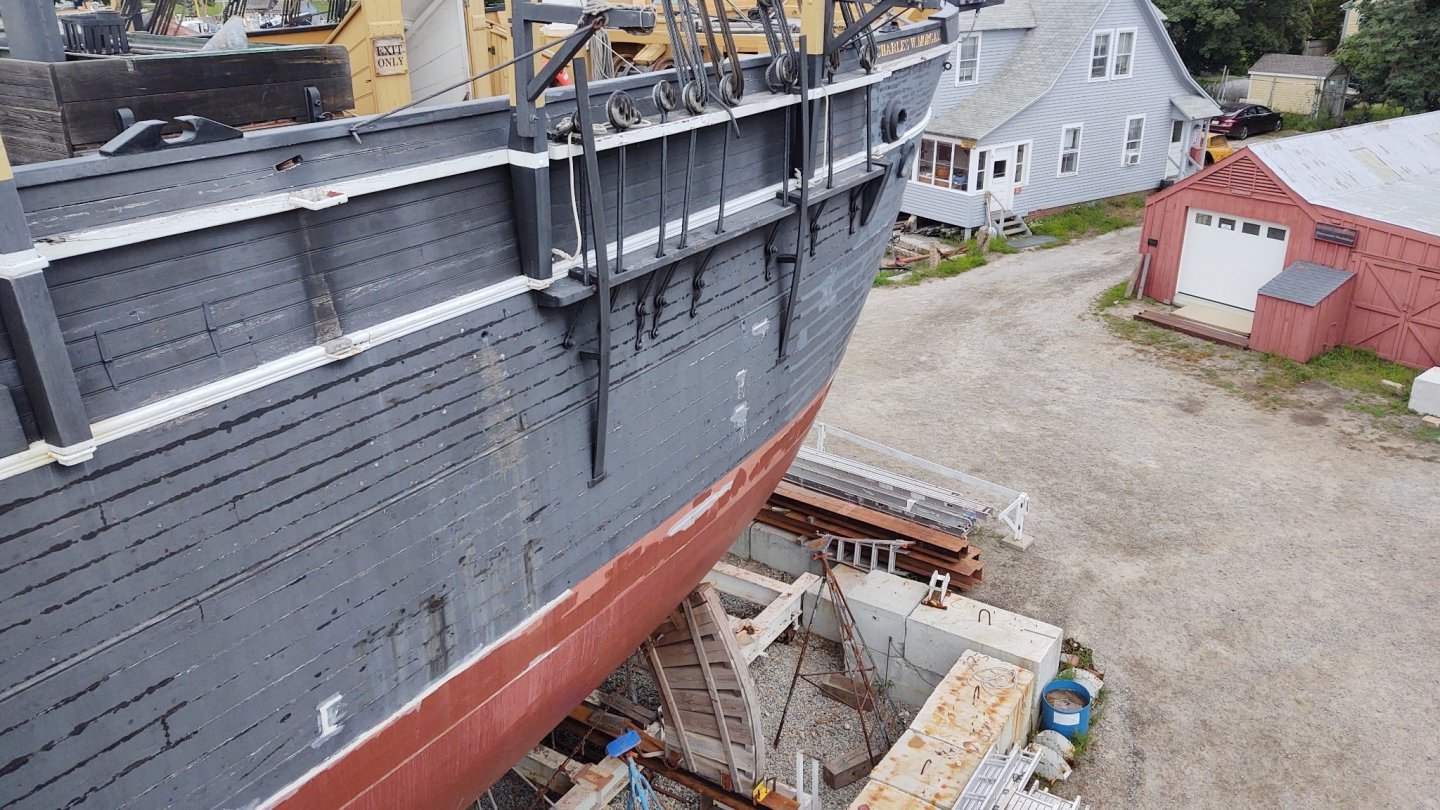
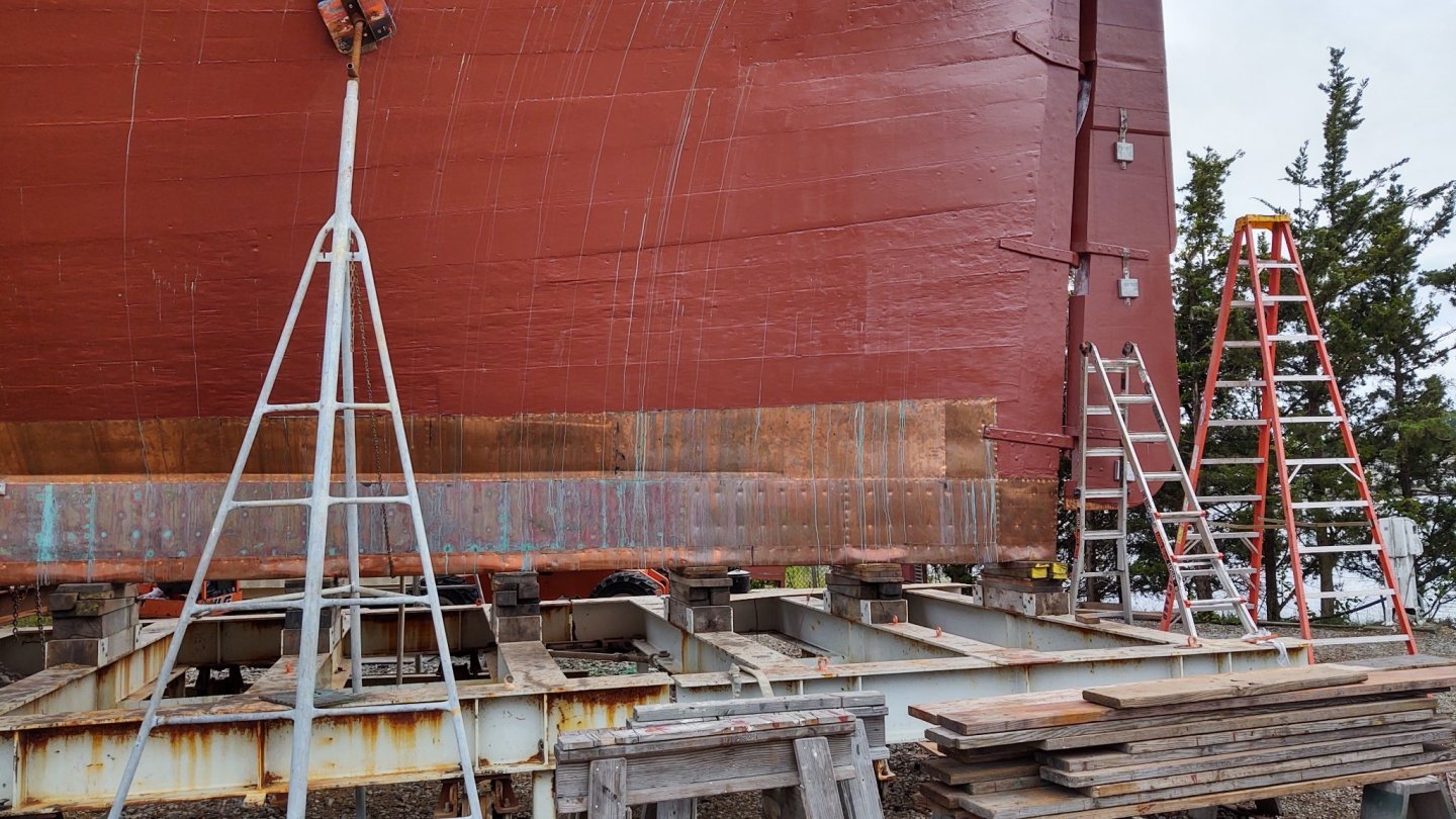
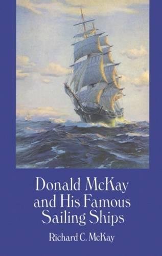
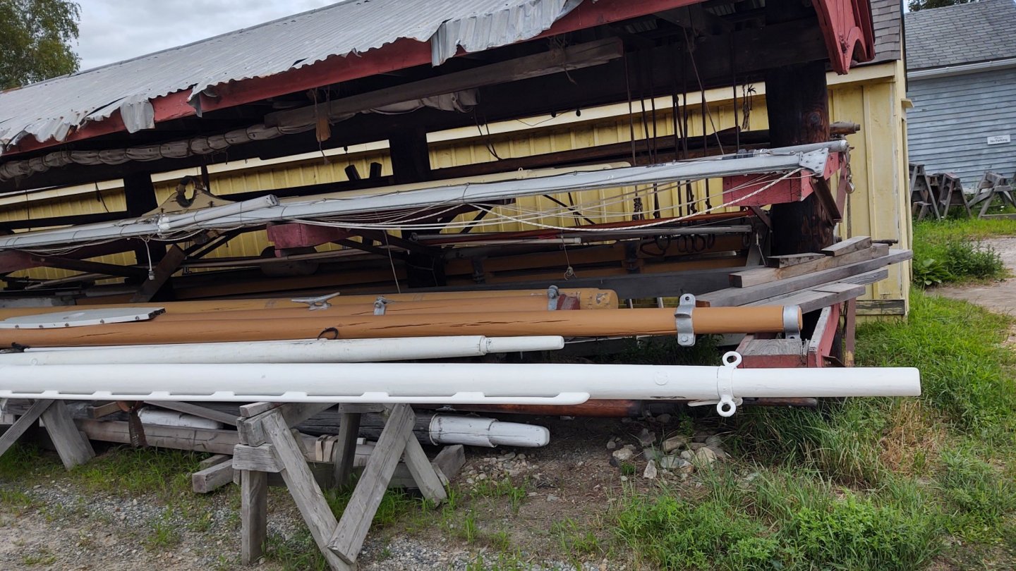
Well, a brief note. We were at Mystic Seaport and the Charles W. Morgan was out of the water on blocks getting some restoration work, including, it appears, its copper. Here are a couple of pictures of the ship on blocks and her copper. First, the whole ship. Her copper, fore and aft. I note that in contrast to the way it was described in the Fish instructions, the lower layers seem to overlay the upper belts. I also note that the copper is cut around the gudgeon, rather than being mounted on top of the copper. This makes sense, but I hadn't thought about it looking at models. Other observations. The foremast chain plates have backing links, the main and mizzenmast do not. The mizzen is smaller, so that makes sense, but why is the fore different? Extra strain from the jibs? The man at the museum didn't know. If you want to look at the Morgan's spars, now us the time. They are out for all to examine in forensic detail. And, I got a copy of this book! George K


- 602 replies
-
- 7
-
-
- Flying Fish
- Model Shipways
- (and 2 more)
-
The plans had the gore line marked, which I assume was Ben Lankford's (probably excellent) assessment of where to put it. Transferring it from the side views to the three dimensional object would be a pain, so I located the line on the stem and stern and laid the tape out so that it would flow naturally, thinking that such a flow was the whole point of the change of direction. It looks consistent with the plans, but since they are just guesses anyway, it seemed good enough for me.
-
What Rob said. I'm going to cut the ends of the plates at the gore line so that it will leave an uncoppered section that follows the tape, and then the Tamiya tape line will become the first line of plates in the next row with a changed direction
-
Hello! There are a few others working on this kit, although I think we are all mostly behind you at the moment. @Keithbrad80 has a log, as do I. Welcome to the forum!
- 431 replies
-
- 1
-
-
- Flying Fish
- Model Shipways
- (and 2 more)
-
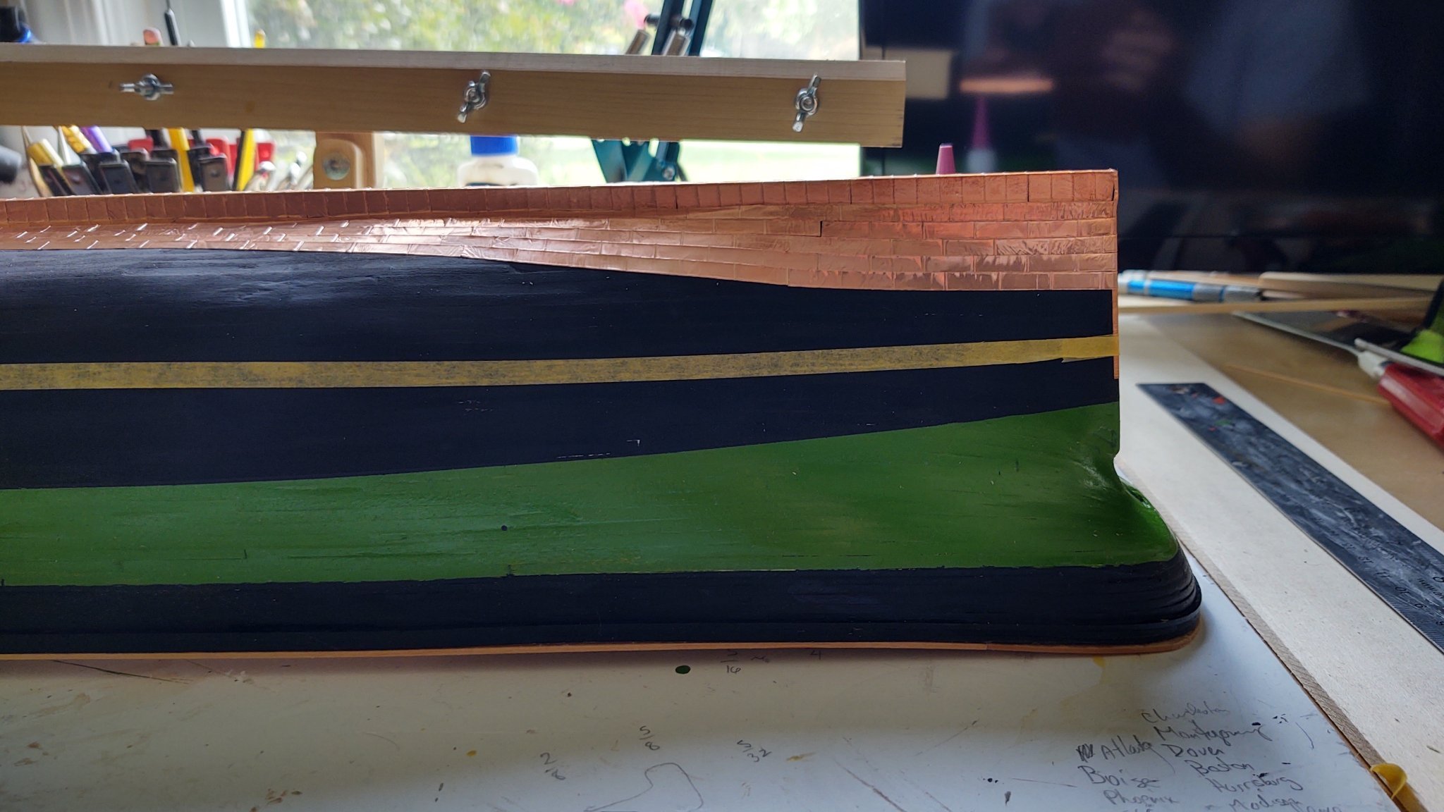
Just a brief update, as we are about to go on vacation and then I need to return one of my children to college, so no updates for a couple of weeks. Coppering is proceeding apace, but even at 6 tiles per segment, I still have a way to go. The yellow Tamiya tape represents the first line of plates in the second belt (i.e. the bottom of the tape - or rather the top of the tape in these pictures) represents the gore line. Stay safe out there, and thanks for looking in and the well wishes. George K


- 602 replies
-
- 7
-
-
- Flying Fish
- Model Shipways
- (and 2 more)


.jpg.979c8224fddedec3284421494deed3f1.jpg)


.jpg.4364145df27bfe6c9baba5e9d3fdaeb0.jpg)