liteflight
-
Posts
206 -
Joined
-
Last visited
Content Type
Profiles
Forums
Gallery
Events
Everything posted by liteflight
-
 Fascinating build log, Steven, and the direct cause of me learning a New Thing ( despite being careful). I found more about the barracouta, and found it’s the same fish as Snoek, which anyone with a UK or South African background will have heard of. It’s Sunday name is Thyrsites Atun, which suggests a relationship to the Tuna/ Tunny/ Atun family, but anyone who has seen one would conclude it’s a distant relationship, as it’s common name of Snake Mackerel suggests My hat is well and truly off to the fishermen who ventured out through the Narrows each day to fish in the Bass Strait.
 -
Well understood! I was not suggesting the the paddles were motorised ( but great idea!) I just mount the solar pump beneath so that the jet points backwardish and the craft imitates the actions of a squid in jet mode
- 110 replies
-
- 3
-

-
- Paddlewheeler
- Ballarat
- (and 3 more)
-
Late, but pursuing! In UK English the very top end of the chuffed scale is “Chuffed to little Naafi breaks” Dont ask, as I don’t know. For non-UK citizens: NAAFI is the organisation who dispense “tea and wads” to the armed forces Presumably in time of war a rest in the vicinity of a NAAFI van was a relatively wonderful time great models, Steven. Good plan and well executed Note: the wee models would run on a flat floor on their paddles; could be motorised, and if ballasted could perform in the bath. BFO: solar fountain ( as used in all my birdbaths to prevent mosquito larvae) reassembled to put solar cell on roof and pump attached beneath boat gives steady silent solar propulsion Might be eye catching as a sales aid in a small round basin near the point of sale
- 110 replies
-
- 4
-
-
- Paddlewheeler
- Ballarat
- (and 3 more)
-
Scrappee Liaison by chadwijm6 - Microaces - RADIO
liteflight replied to chadwijm6's topic in Non-ship/categorised builds
Mmmmm. Scrappee requires very light radio gear and servos and flies on a single lithium polymer battery ( 1S, or a nominal 3.7volts). Your Heli gear may well be “standard” radio, where the servo plugs alone weigh more than a micro-servo ( about 1.5 gms) Unless you are seeking the ultimate in lightness, the equipment does all plug together, and probably requires no soldering at all. For anyone interested, all the equipment to fit out Scrappee is available on the Microaces website as well as the rest of their model range I’m an indoor flyer, but have no relationship with Microaces, other than as a future customer ( I fancy their DH Dragon Rapide) andrew -
Amusing; close, but no cigar! Named after lord Melbourne (?) Brit foreign Secretary, who took his title from the village of Melbourne in Derbyshire. Melbourne means the place of Melde Melde is Chenopodium Album, commonly known in UK as Fat Hen, and was cultivated in the Middle Ages as a vegetable and eaten a bit like spinach. Note: there are dozens of Melbournes in Britain, as the stuff grows everywhere It could have been worse. He might have taken the title of Lord Fat Hen! sorry to have hijacked your thread, Steven. I’ll climb back under my flat stone andrew
-
Steven If your travel plans included Melbourne* in the foreseeable future, I have about a pint (imperial) of Matt Acrylic Medium, and you are welcome to a dollop ( as well as a box of box) I believe that the pouring medium is relatively very runny, and so contains a lot of acrylic solvent. The Matt medium is more pasty than liquid, and for the application of seams to sails would have to be diluted a bit ( acrylic thinners) or applied with a weeny roller Fwiw, I use a satin acrylic varnish as an adhesive for tissue/cloth, etc, . Most probably it comes as a matt version as well * As far as I am aware the only State Capital named after a vegetable. I exclude Brussels as that was t’other way about andrew Pumped from looping a Concord model today, indoors and by accident!
-
In a Blinding Flash of the Obvious I have just realised the wakeboard is the modern embodiment of the green plastic foot-base on toy soldiers! Steven’s comment above triggered the BFO The rudder/tiller combination is fully reversible - all wave forces, shocks and running into dead second-hand hippppopotomi will kick back into the tiller and the steersman’s ribs if the stance is correct. Big regular forces (waves) could probably be resisted by a good lateral stance. Additionally there would be frequent small shocks from the hydrodynamic forces and possibly these would make the steersman’s ribs painful, calloused or both None of the above is unique to the trailing tiller system, it is just that ships of this era had, essentially, very short tillers (compare with the length of tiller of say a Naval Cutter or Brixham Trawler) which would make the steersman’s strength a necessity. As a spokesman for the Department of Useless Information (DoUE) I can observe that the an old term for the Steersman was Gubernator ( Latin) from which we get the terms Governor (US) fly-ball governor ( engineering and frequently US) “Guvv’nr/ Gov” ( London Cabbies) Parthian thought: you could carve yourself as photographed*, Steven, to make the model truly distinctive *with or without wakeboard andrew
-
Wire will make the strongest, especially if you use steel wire. I’m not sure of the diameter of the stanchions and rails but at the scale I would guess they would be in the 1 to 1,5 mm region, You could consider different materials like plastruct extruded sections ( ABS material ) which can be joined by solvent welding, but they might not be strong enough take even light handling. Brass is easy to cut, solder and finish. If you use steel wire - do not use the wire available in model shops, as this is Piano wire ( music wire to our US cousins) which is high-carbon, very hard and stiff and therefore quite difficult to cut to identical lengths, bend to repeatable curvatures, etc. Engineers would say it is almost glass-hard. Soft iron wire is probably too soft, but is easy to work, bend and solder*. Samples are florists wire and some fence wire. Bunnings do big hanks of garden wire - might be worth a look. Piano wire can easily be tempered back to a useful hardness - same as your Uhfbert sword, but much faster ‘cos of its thinness. Heat to dull red and allow to cool in air will produce very soft temper *With the correct flux! Sorry, I have rabbitted on too much. soldering easily learned - especially when shown the method. Probably Pat’s resistance soldering setup is readily controllable and he might share his wisdom about it 4 secrets** of good soldering: Cleanliness Cleanliness Right Flux Cleanliness Enough Heat! **. Like the Garden of Five Surprises
- 110 replies
-
- 9
-
-
- Paddlewheeler
- Ballarat
- (and 3 more)
-
Yes, but the staples then rust. Me, I use masking tape to hold the covering material to frames made of 1/4 square hard balsa ( 6 mm in newfangled money) I have heard of people buying old pictures in Op Shops ( Charity Shops, Thrift Shops) and scrapping all but the frames. If made in the last 30 years the frames themselves are probably Ramin Thank you for the glimpse into carving real chaps from fruit-wood. We can just hope that you find a source of boxwood. I like the photos of You-as-steersman. Good way to visualise the stance. I do wonder how much the tillers would kick back in choppy weather and do the steersman’s ribs a power of no good. He would also probably ( my speculation) need one foot thwartships to brace him against the kicking of the tiller Were there two steersmen, one per rudder? And how did they communicate and coordinate the steering? Two independent quarter-rudders make it possible to get considerable braking by turning both inboard (or outboard, but that would require longer arms!)
-
Nice idea of the jig ensemble - it works in principle even if it may need modifying in detail. AND At least the frame squarifying jig will work on any future ship that has frames and a reasonably parallel keel.
-
Lovely work Steven, and fascinating research and evidence from the massed ranks of MSW stalwarts. My belated tuppence worth: All that has been said about curved keels is true and very valid. I can attest to the fact that even the slightest rocker in a keel improves turning ability enormously ( I used to race R/C yachts for amusement) Better turning = less rudder movement to get the required turn Less rudder movement = greater boat speed I remember reading the detail of the keel of one of the big, excavated Viking burial ships (almost certainly Oseberg) and learning that the main keel member was a single riven oak log. What boggled my tiny mind was that the overall length was iirc over 80 feet ( 24M) with over a foot ( 300mm) of rocker. ( as well as the complex cross section to accept the garboard strake) Good jig for the mast steps! andrew
-
Steven, Blast from the past, which might be answered while you are gathering your equanimity The shallop/ chaloupe/ ships boat. it appears to be about the size of a ladybirds wingcases ( ladybug to our US cousins) could you give me the overall length, please. I have just looked back through your build and the wonderful pics of the finished boat. Judging by the scale on your cutting board, and the VAST match, it seems to be close to 45mm long I have a sudden fancy to (try to) make one, or more. Once I have a form, I aim to try planking with thin pine (0.007”, 7 thou), paper and perhaps papier-mâché, oh and plunge-forming. tia, Andrew
- 740 replies
-
- 2
-
-
- Tudor
- restoration
- (and 4 more)
-
Steven The cloth of Gold sails are magnificent, they will be the eye-catching “stars” of the show ( and probably outshine Hal) I’m sure you have documentary evidence for the Tudor clothes-peg andrew
- 740 replies
-
- 1
-
-
- Tudor
- restoration
- (and 4 more)
-
HMCSS Victoria 1855 by BANYAN - 1:72
liteflight replied to BANYAN's topic in - Build logs for subjects built 1851 - 1900
Pat This supplier stocks the Bergeon range of Watchmakers supplies, might be worth a call after the holiday. https://www.australianwatchclocksupplies.com.au/tools.html andrew- 1,013 replies
-
- 2
-
-
- gun dispatch vessel
- victoria
- (and 2 more)
-
HMCSS Victoria 1855 by BANYAN - 1:72
liteflight replied to BANYAN's topic in - Build logs for subjects built 1851 - 1900
Hi, Pat Noted! AND Following Welfalck's excellent suggestion of watchmaker's Pivot Drills https://www.esslinger.com/drill-press-drills-and-more/ https://watchmaking.weebly.com/drill-bits.html and, as it happens they are precise spade drills, available in sets or singles (see first reference) Googling the Bergeon (No. 1713) reference will extend your horological linguistic skills not a little And yes, the homemade piano wire reamers/drills make a wire-size reamed hole which is not necessarily on the centreline of the gadget that turns them but for thin brass they follow the centre-pop! andrew- 1,013 replies
-
- 3
-
-
- gun dispatch vessel
- victoria
- (and 2 more)
-
HMCSS Victoria 1855 by BANYAN - 1:72
liteflight replied to BANYAN's topic in - Build logs for subjects built 1851 - 1900
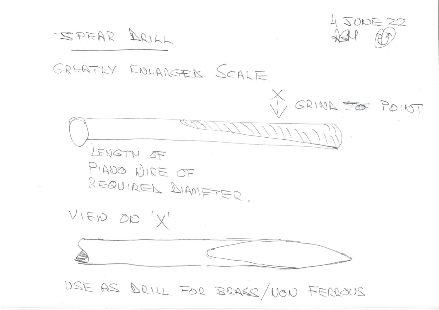
Hi, Pat Don't want to be a nuisance on your thread, nor was I suggesting that you make a fluteless drill by forging and quenching in the blood of a red-headed virgin (the best type) Its probable/possible that you already have the necessary tools! Alternatives are: High-speed (preferably Carbide) burrs (liberate from your friendly dentist, if necessary) Diamond Burrs Needle files or a home-made spear drill - see sketch attached I hand-drill small holes using an Archimedean drill as a holder - generally centre-pop them with extremely sharp point (think compass point ground from a masonry nail or dead small drill shank) then turn over and needle file the back to remove the pip. This often leaves a pinhole to be enlarged Then any of the listed gadgets (and rotary broaches) will enlarge the hole to your desired diameter without applying much torque Note 1 - the spear drill is an excellent reamer of holes in sizes up to 5 or 6 mm (I use a dead drill shank rather than Piano wire as cutting piano wire in these sizes is very little fun) Note 2 - grinding a spear drill in 0.5mm (20 thou) diameter needs to be done slowly and with copious cooling as you grind to avoid overheating the high carbon wire. Have a deep mug or water and keep cooling the wire before it needs it. Note 3 - If you get the whole end red hot - heat it white hot with a blowlamp and quench in the water ! Viola! Glass hard again! Note 4 - You COULD grind both sides to a chisel point, then grind it elliptical like a glass drill but IMHO life is too short and I, for one would not presume to measure the diameter or cylindricity of your holes (which will no doubt house a shackle pin, or similar)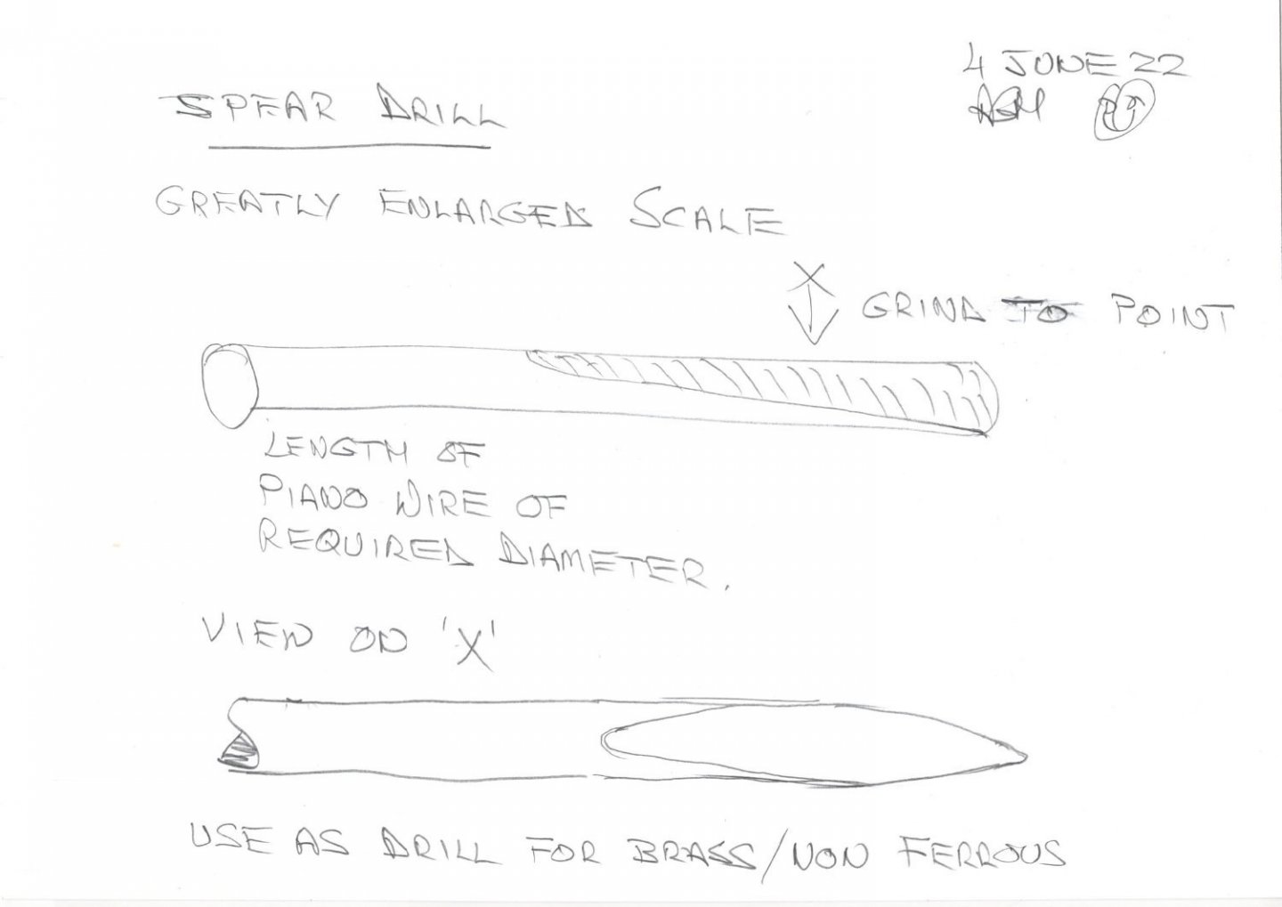
- 1,013 replies
-
- 3
-
-
- gun dispatch vessel
- victoria
- (and 2 more)
-
HMCSS Victoria 1855 by BANYAN - 1:72
liteflight replied to BANYAN's topic in - Build logs for subjects built 1851 - 1900
Pat, I can see the problem! As usual I do not know the whole answer, but can suggest some directions which might lead to the answer! When a twist drill breaks through, it has a strong and inevitable tendency to “grab”, especially in brass. Quite possibly it is this grabbing, in association with heat, that breaks the solder joint. Perhaps use a drill which does not grab - ie, not a twist drill. Examples of this are the centres of spade drills, glass drills and/ or make your own from a length of piano wire of the correct diameter (I will sketch and send later) Solder in a less breakable way. Silver solder with the correct flux and a micro flame torch ( together with extreme cleanliness) will make the joints in seconds ( and as a bonus anneal all the material so that it is softer to drill) . Drop the hot assembly into pickling solution and viola! - soft pink and strong spider band! Cheat royally! - make the lugs of the spider band of small “U” shaped wire bends so that they are born with a hole. Solder as above and if necessary flatten after pickling to flatten the wire and reduce the size of the hole. I made the jib traveller on my Thames Sailing Barge by a modification of (3). One radial hole drilled at each lung position to fit wire lug. U shapes bent with one Longer leg which went in the hole. All jigged and solder soldered, pickled and cleaned up. Bore cleaned up removing the longer legs of wire I have rambled a bit. Hope some part may be useful. Underwood’s book on rigging shows his method of making these - essentially a hybrid os 2and3 above with a drilled hole in the band and a nib on the Sheet lug to fit in the Hole. Jigged with a twist of wire to hold all the lugs compressed into place and silver soldered on charcoal block andrew- 1,013 replies
-
- 1
-
-
- gun dispatch vessel
- victoria
- (and 2 more)
-
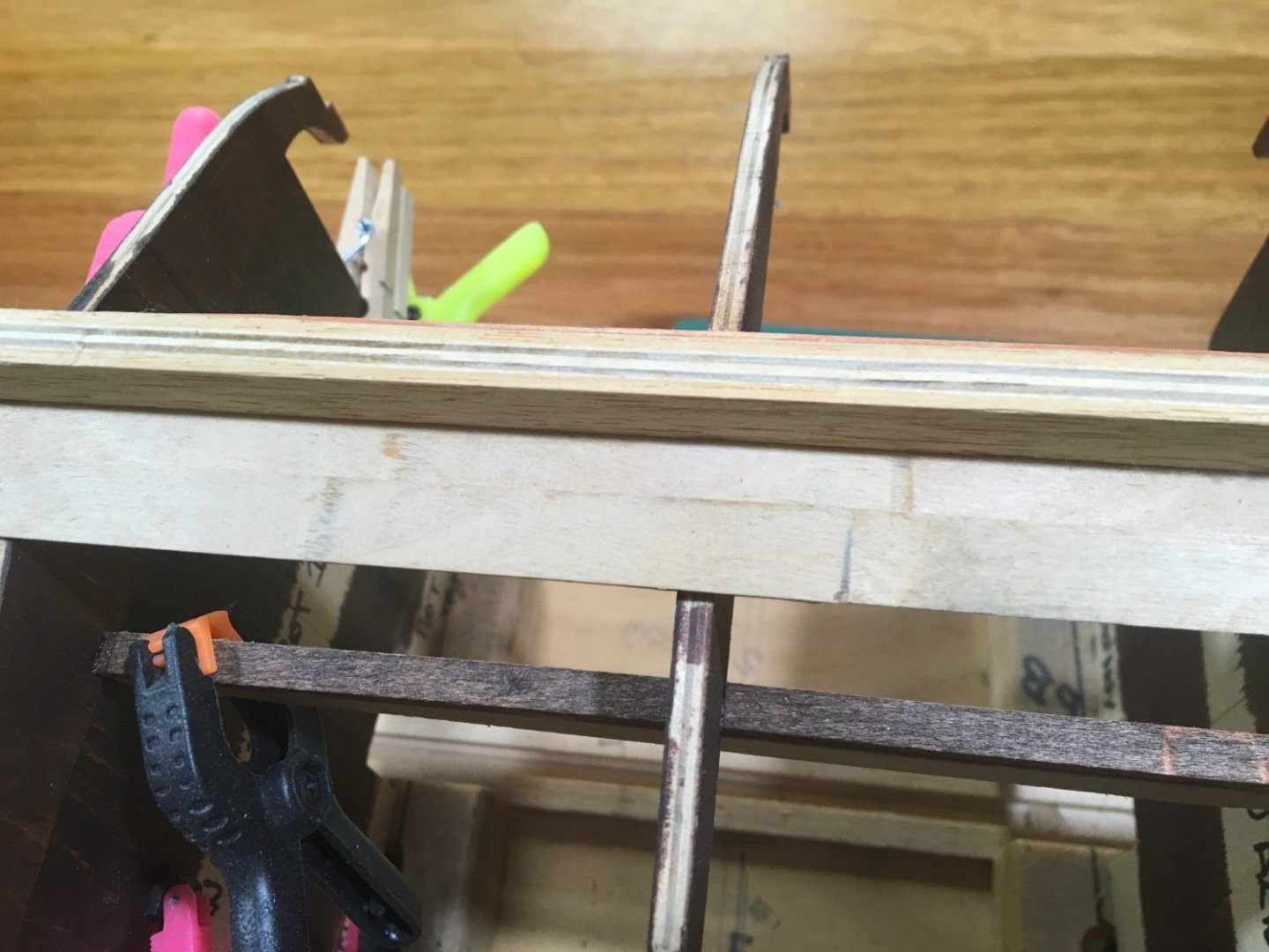
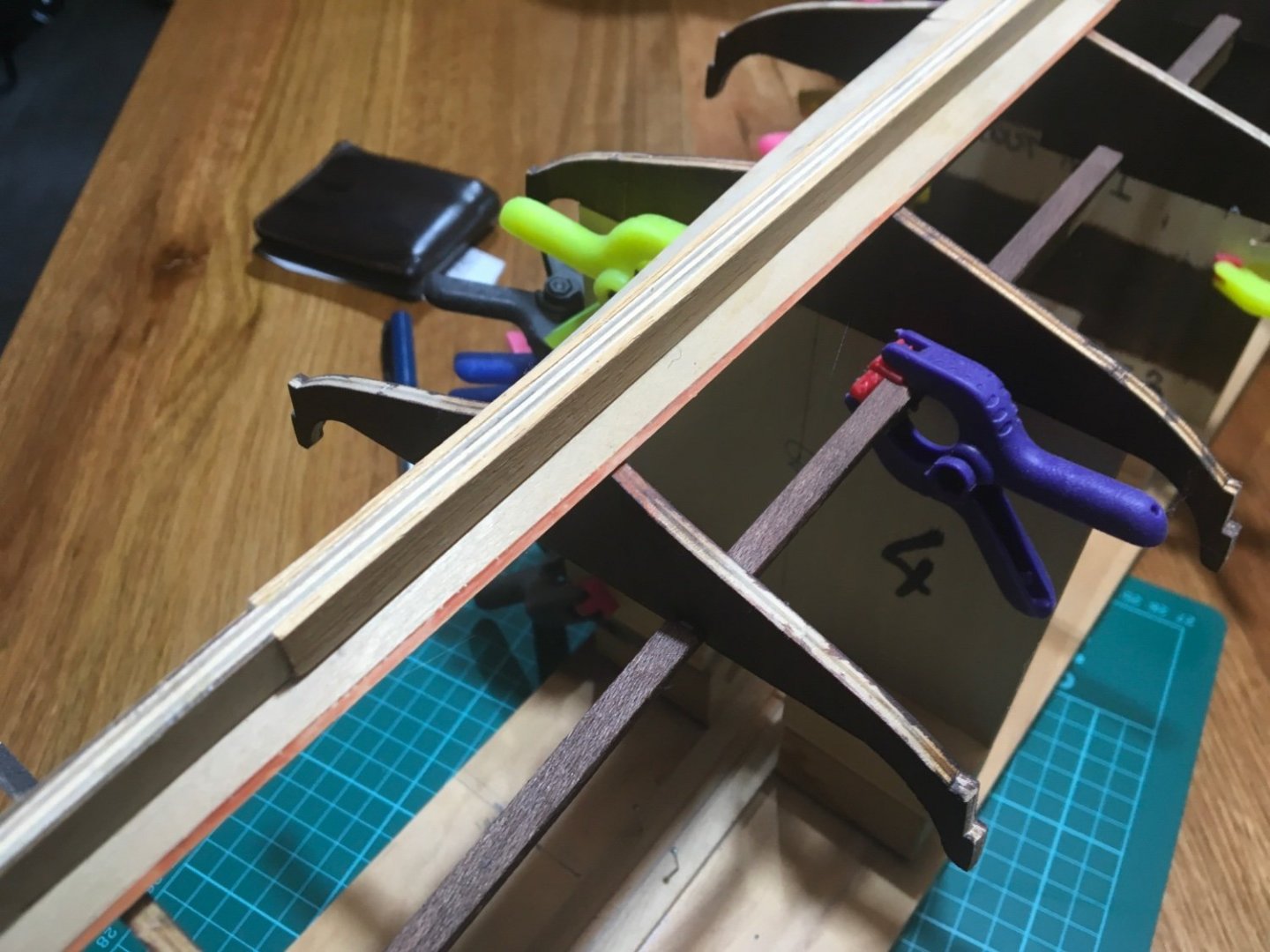
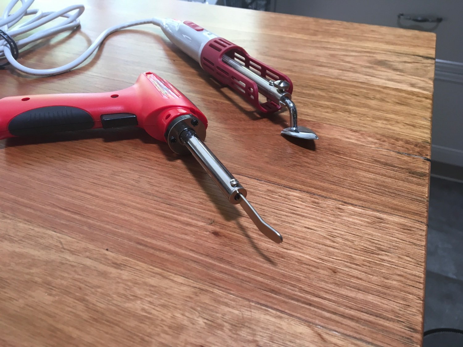
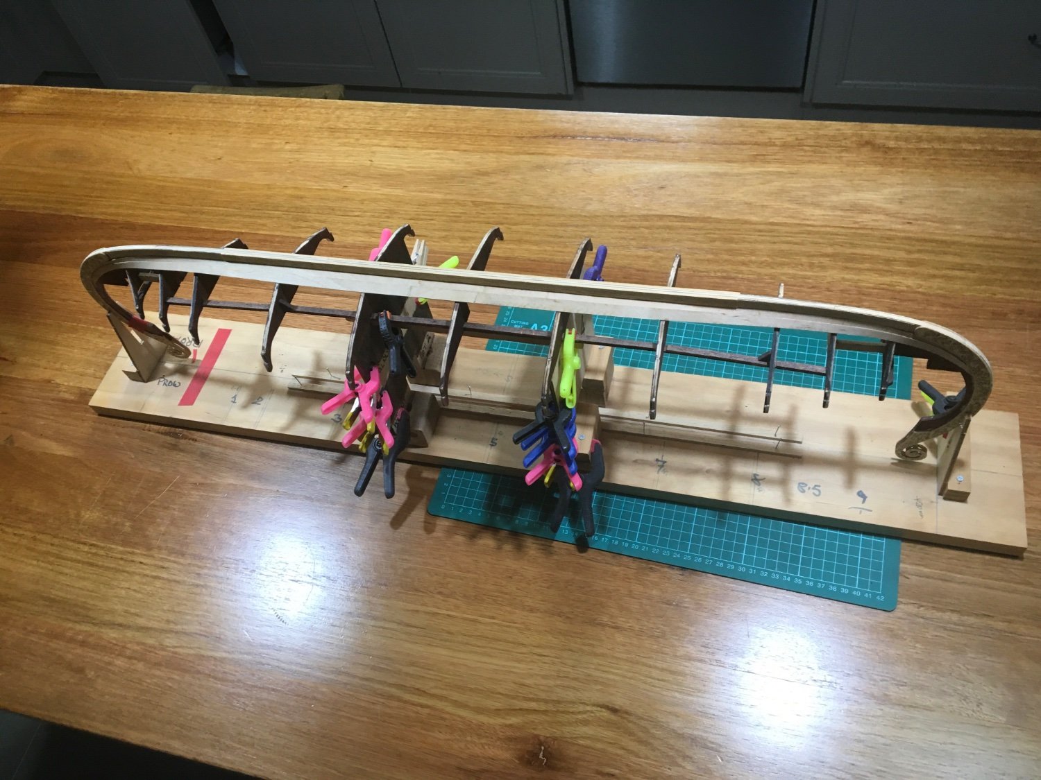
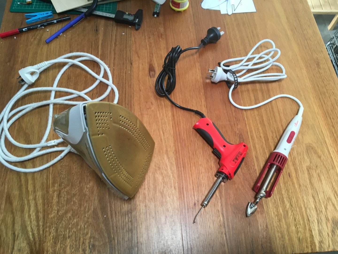
I am in the middle of a major tidy and sort of the entire house and garden, triggered by the death of a modelling buddy. He died leaving a VAST air-conditioned modelling shed packed with 40 years of many fields of modelling hardware. I and flying colleagues have sought to clear the shed, convert the contents to cash, and return the proceeds to his widow. Among the relevant items are two electric covering irons, photos attached, which I expect to be a neater and more manageable heating tool. Both of these are sealing irons used for the smaller corners and seams of heat- shrink covering for model aircraft. Normally they would be temperature-controlled, but these may be the “economy” models. Easily rectified with a mains dimmer in the supply. I included the household iron Originally used for the first strakes. Not easy to use among a line of clamps! Now to make progress! 1) Test the new heat sources on scrap materials 2) Obtain dimmer if required - the household iron was set to “max” if I remember right so dimmer may not be required 3) clamp up and carefully reheat the strake which is not fully stuck down 4) Prepare next half- strake, scarf end where it joins existing strake 5) Mark, mask and apply coloured PVA ( carpenters) glue to the fat 1mm overlap I think five steps is sufficient for now andrew

-
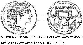
I went hunting for Illustrations of the rostra And this is what I have so far
-
My Admiral used to refer to this as his “ row of pink tents” voice And we digress! I am sure none of us has ever done that before Having looked at the resource on rams, I went on to check out the rest of the site - interesting stuff and a great resource andrew
-
Thanks, Steven it was the Atlit ram that I remember being found and discussed The list is interesting and the thumbnail pictures take you to high-quality illustrations When people addressed the crowds in the forum of Rome, they did so from the “rostra”. I was always taught that these were the bows of warships captured by the Romans ( presumably complete with ram). And I assumed that they were the whole bow of the ship, with enough deck to orate from. Does anyone know of any illustrations of a rostrum in the forum? My main source is the film “ Carry on, Cleo” and I would hardly claim it to be authoritative ( although it did ascribe to the dying Julius Caesar the memorable line “ Imfamy! Infamy! They’ve all got it infamy”) sorry andrew
-
Came across this while scanning the general news https://www.livescience.com/medieval-cargo-ship-estonia First picture in the article seems to me to show thwartship beams passing through the sides, and generally the parts pictured seem to be complete and intact. Interesting to see how the investigation proceeds andrew
-
I noticed that the article mentioned a large number of anchors all aligned in the same direction, suggesting this might have been the Roman fleet cutting their cables to close the ambush. I am also so old that I remember much debate about “rams” ( rostra) when Olympias was built. If I remember aright there was one found in shallow water somewhere near Tyre at about that time, and I think it may have been the only one identified. And here is at least one, potentially several more. I imagine that a bronze casting of this size would a) last forever underwater* b) be a significant part of the total cost of a warship *before metal detectors and greedy scavengers andrew
-
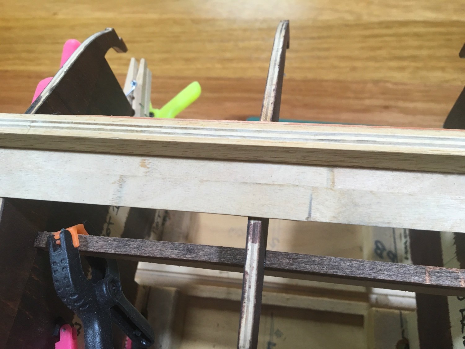
Thanks Steven, I have now! Thank you for that. Warm thanks, too, to everyone who contacted me with messages of sympathy and support. Much appreciated and very valuable to me at a difficult time. So, as I was saying....... I have reviewed Oseberg as she is and I find good news and less good news. I had commenced the clinker planking, having decided that “my” overlap would be a thick 1mm Easy decision, but how do I do that precisely and repeatable? + the current state of play: both garboard strakes fitted with scarf joint between the two ( precut) parts of each strake (just for reference, the clamps are merely parked where they are) i have added a second full strake on one side, using a method which I have not seen before, so probably worth describing ( even if only to give you a larf) I aimed to scribe my fat 1mm overlap on the garboard strake. First attempt was using compasses, of which as a former Engineer I have a modest plethora. None of them were designed to work or be rigid with a 1 mm gap. Most were designed to use a lead about 2.5 mm dia, sharpened to a chisel point by arcane methods known (only) to draughtspeople. However sharp the lead it gave a bad result! I then remembered cutting thin styrene sheet using a hard pin pushed through a balsa sheet with a ply edge guide. So postage stamp size bit if hard 1/8 balsa with a length of thin ply sticking down 2mm to slide along the edge of the plank to be marked. Lay it on its back and put a strip of fat 1mm width against the shoulder. Push pin through touching the strip replace pin with 0.5mm drawing pencil lead and adjust till it barely protrudes ( or if you prefer - till it sticks out a wee bit) Viola! You have a cunning device which marks a fat 1mm from an edge And yes, it works only when the curvature of the edge is very gentle. And also yes, this concept can be developed to work with sharper curves, both concave and convex - but no need here. So the edges of both garboard strakes are clearly marked with the overlap. A cardinal principle of my build is that I don’t want glue anywhere but in a joint, because it would require clean-up. IMHO even a careful clean up of a wood glue is likely to afffect any subsequent finish, so I aim to avoid that by removing the possibility of glue being squooged out of joints. My strakes will be fixed by heat-activated wood glue. I believe it would be helpful to know Exactly where the glue is, so I mixed acrylic paint with neat PVA wood glue ( I seem to remember it was an umber) Like this i had masked to the pencil line with fine masking tape and applied two coats of the coloured glue Reason for that type of colour - the future holds dark staining of some sort - and any accidents of a generally wood-like hue should be unobtrusive. The less good news On careful inspection, I found that a part of the glued strake is not stuck. I’m not downcast, however because: I activated the heat sensitive adhesive with a full size family steam iron I cannot be sure that these areas were ever stuck - this was nearly 18 months ago. I have since been given not one, but two neat little devices intended for applying delicate heat shrink film to model aircraft ( airplanes to American friends) photos to follow Please feel free to guide me in matters of technique or writing style. I have written at length in this post to catch up with where the ship sits today, and because the PVA/ acrylic ( or watercolour) trick may help someone else. andrew