

liteflight
-
Posts
206 -
Joined
-
Last visited
Reputation Activity
-

 liteflight reacted to Louie da fly in 10th-11th century Byzantine dromon by Louie da fly - FINISHED - 1:50
And on to the lashings for the side rudders. The diagrams of lashings in the TAMU paper I mentioned on the previous page weren't much help, so I worked up something of my own. Remembering back to my days as a Sea Scout at the age of 14 I remembered a lashing we'd used. But first I had to re-teach myself how to do a clove hitch, something I hadn't tried for 57 years, and even back then I'm not sure I really mastered it. Took me two or three goes with the instructions in front of me, then maybe half a dozen tries without. And I think now I can do a clove hitch from here on in - something I think is going to be very useful in future models involving ratlines(!). The clove hitch starts the lashing:
Then round and round:
This is a sort of universal joint made from rope. It allows the rudder shaft to pivot left and right for steering under the influence of the tiller, just as in a stern rudder. And it can also swing upwards around the beam so the rudder lifts out of the water - either when only one rudder is in use, or to enable the dromon to be pulled up onto the beach stern-first.
Then for the lower lashing - this one is made of lighter rope. According to the TAMU paper on the previous page of this log, if the rudder hits a submerged obstruction, instead of the rudder shaft being shattered the rope will break allowing the rudder to swing up out of the way. Before beaching the ship this lower lashing is untied.
That's all for now . . .
-
liteflight reacted to Louie da fly in 10th-11th century Byzantine dromon by Louie da fly - FINISHED - 1:50
Thanks, Wolf. That's very flattering (blush)
Okay, I bit the bullet and installed the anchors and cables without involving the windlass - they're catted and fished, and the cables vanish under the forecastle as though they're coiled there.
I'm not sure if I should cut the free end of the anchor cable a little shorter. It looks like it might be a little long.
And I did something I've been wanting to do for a long time, and which I wasn't willing to do until I was near the end in case I broke it while working on other things - I've finally added the chain that supports the ramming spur at the bow.
I attached the chain to one of the eyebolts I'd prepared earlier.
Then made an "iron" (actually thin aluminium from a catfood container) strap to go around the spur. And drilled a hole in the front face of the forecastle, inserted the eyebolt and added a dab of CA glue to keep it in place.
I cut the chain to length and added another ringbolt on the other end. Then put the strap on the spur and glued it on with CA, and drilled a hole in the top for the second ringbolt.
And inserted the ringbolt and glued it in place.
VOILA!
And I've started making the tillers, using the "poor man's lathe"
That's all till next time.
-
 liteflight got a reaction from Keith Black in 10th-11th century Byzantine dromon by Louie da fly - FINISHED - 1:50
I feel that I should point out that your remediation was not technically bodging, as that profession works with green timber.
But we know what you mean, and I am being pedantic
Did the repair involve sawdust and glue?
-
liteflight got a reaction from Keith Black in 10th-11th century Byzantine dromon by Louie da fly - FINISHED - 1:50
Wonderful, Louie!
Very glad you decided to carve the active men in the rig - they are shaking out the furl and loosing the gaskets, I expect.
Well carved. I expect that you mentioned the wood you are using. It looks home cut and dried.
Pity about the ankle; but I realise that if it was all easy it would not need your talents
-
liteflight reacted to Louie da fly in 10th-11th century Byzantine dromon by Louie da fly - FINISHED - 1:50
While I'm thinking about the anchors, I'm also working on the side-rudders (steering oars if you prefer) .
I'd originally intended to attach the rudders to the lower through-beam on each side, but I realised it wouldn't be able to pivot upwards if I did, so I used the upper beam instead. So I had to cut a hole in the planking on top of the support structure, for the rope that fixes the rudder to the beam.
The rope allows the rudder to pivot around its vertical axis (for steering), and with a bit of luck it will also allow it to swing upwards out of the way when only one rudder is in use. The kind of lashing or whatever that was used is (of course) unknown, so I'm going with the theoretical one from the TAMU paper "The Development of the Rudder, 100-1600 A.D.: A Technological Tale" by Lawrence V. Mott ( https://nautarch.tamu.edu/academic/alum.htm) to see if it works.
I drilled a hole in each rudder and inserted a brass pin.
and a corresponding hole in the upper beam on each side of the ship
Here are the rudders dry fitted
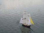
There is only one Byzantine picture that shows a tiller on a side rudder:
I'm probably going to copy that for my own. To get the tillers at the right height I put the steersman in place next to one rudder and marked where the hole for the tiller would have to be.
Note that I haven't yet finished the steersman's arms - I'm holding off till the tillers are in place. I wasn't sure if I wanted one tiller to be swung up out of the way, but I think it'll look better with them both in operation. Which means I have to carve another steersman.
-
 liteflight got a reaction from mtaylor in Bohuseka by bolin - FINISHED - scale 1:12 - Swedish west coast rowboat
The spar is ( perhaps not surprisingly) a sprit. Probably a Dutch word I think, and pronounced “spreet” on Thames Barges.
Gloriously the rope holding the bottom end of the sprit is the snotter.
Beautiful work on the boat, Bolin. Extremely clean woodwork and a good result.
-
liteflight reacted to vaddoc in 21 ft Yawl Longboat for a Sixth Rate by vaddoc - FINISHED - Scale 1:10 - Plans from the National Maritime Museum
Well, two new things to announce. First that the hull is finished. Secondly, I discovered another mistake!
This one was in front of my eyes since the beginning. Simply, the body plan lines are indeed to the inside of the skin, but all other lines are to the outside! This is dead obvious looking at the drawing.
What a mess! I have drafted all lines to the inside of the skin. Still, with a plank thickness of 2 cm (so that in 1:10 would be 2 mm), the error is not significant but could explain why I had such difficulties to get the hull to work.
Still, lofting the profile view to the inside of the skin instead of the outside, creates some unique new problems that I had to overcome. I will try to explain these with some images.
As I have defined the inner skin, I can easily get the shape of the frames at any position. What is left is the rabbet line at the keel, the stem and sternpost. To get this line, the outer skin is needed. This was very easy to get by asking the computer to offset the inner skin by 20 mm which is the plank thickness.
Now, the rabbet line (the line the outer skin meets the keel) should be horizontal at the keel. The reason is that this line is given straight and the lofting is done on this basis. But I lofted considering that the bearding line (the line the inner skin meets the keel) was straight. So the skin pivots against the bearding line and the rabbet came out curved in two planes. The next snapshots show the problem.
This is the face view of the two skins, the keel area is magnified in the second snapshot
Nothing I can do for the bend downwards. To level things off however, the keel surface needs to come out and meet the outer skin. So I trimmed all lines to the same level. No idea how this will work when planking but the difference is about a mm or so. I think it will be fine.
In profile view, the rabbet takes a small dive but it should not be visible. The black line is horizontal and the red line is the rabbet
After this there is not a lot really to do. I projected the part of the transom that meets the planking just to see the bevels and the shape of the sternpost. There should not be a need to fair the frames at all as all the bevels will be known and cut in advance.
Joining the two halves with a keel 80 mm wide gives us the final boat shape with the inner and outer skins
I now need to decide whether I will use steam bent ribs or solid frames. The position of the temporary molds for the lapstrake planking will be such that the same screw holes would be used for the molds and the permanent frames. I would like to leave the planks unpainted so no rogue holes allowed. This might change though.
What is needed now is to finalise the shape of the stem and the transom and to figure out the positions and shapes of the frames and subsequently the positions and shapes of the molds. I ll do this when I am ready to start building this boat. A couple of cant frames will be needed as well
I ve learned a lot from this exercise and I dare say I now understand boats better. The error in lofting did not change the shape of the boat significantly as it was limited only in the rabbet and also due to the small thickness of the planking. This is good as I do not think I could start over for a fourth time!
Thank you all for your likes
Vaddoc
-
 liteflight got a reaction from Louie da fly in Oseberg Viking Ship by liteflight - Billing Boats - 1/25 Scale - 9th Century
Thanks, Kris
I’m going to think of that as a large 1mm.
Tonight I made two versions of a “marker of lands” having discovered that the compasses I have are not accurate with their jaws so close together.
-
 liteflight got a reaction from KrisWood in Oseberg Viking Ship by liteflight - Billing Boats - 1/25 Scale - 9th Century
Thanks, Kris
I’m going to think of that as a large 1mm.
Tonight I made two versions of a “marker of lands” having discovered that the compasses I have are not accurate with their jaws so close together.
-
 liteflight got a reaction from Sea Hoss in Oseberg Viking Ship by liteflight - Billing Boats - 1/25 Scale - 9th Century
The road to Hell (should probably be calling it Hel in posts about a Viking ship) is indeed paved with good intentions.
This post, much delayed by family business, is about more preparation to plank.
I got to thinking about joining the two halves of each strake, and a method of making repeatable scarf joints - ideally I will have a couple of "rivets" through each joint, but that will emphasise that there are very few strake joints in a large and long ship. To be considered.
I have a Microlux palm belt sander, and its "dock" so I proposed to make up a jig for the correct angle of scarf, and thus produce repeatable, neat joints.
The little belt sander, with the jigsaw and drill in the same series were wonderful presents from my Admiral, who positively encourages me to build boats, planes, anything. They are useful little tools, running on 12 to 18VDC.
The variable speed drive (VSD) for the whole range of Microlux tools naturally runs only on 110VAC as it is sold by MicroMark in the US. The VSD, is in fact German made , so the original was probably 240V, or more likely dual voltage. It always seems sad and a little ironic that a lot of natural flexibility is lost when US companies sell them as 110V only.
I'm an engineer - I have a large 240/110 transformer to power the Micromark gadgets (I have their Table Saw as well, Japanese manufacture and 110V only).
So with a little fitting and fettling, I have a scarfing jig which sands a 23 degree angle on the ends of strakes
This is the Microlux belt sander in its dock
Wooden part slides towards belt, guided by three bamboo pegs in the slots in the baseplate
Well, I tried the contraption with 1.5mm obechi, and found that the belt was nothing like vertical, so a little packing of the recess that the sander fits into took care of that.
It was noticeable that the belt was not running smoothly, so I took it off to investigate
2 evident problems:
Nylon idler wheels each had a large "pip" standing up on the surface - looked like the injection gate, but who in their right mind would put an injection gate on the running surface of a wheel? Cut off and dressed down. The abrasive of the belt is joined by a long scarf and held together by thick, strong adhesive tape. This thumps each time it crosses the pressure plate whether you are sanding or not - I'm still thinking about that and a solution for it So with the belt running as smoothly as possible, the jig produces a square and reliable 23 degree scarf.
Why 23 degrees? I hear you ask. Well I am aiming at a similar scarf length that I have seen in many builds of replica Viking boats, and they seem to vary between 1:1 (length of scarf to thickness of strake) to 2:1. I choose 2:1 and for that the angle is arctan 0.5 which is 23.5 degrees, give or take a milliwig.
It is also very close to the earth's inclination from the normal to the ecliptic plane. Hence the Tropics are at Lat +/- 23Degrees 16'.
Must be some cosmic significance there, but it escapes me for the moment.
Each of the stakes is supplied as two halves, hence the entire Garboard Strake is 4 pieces of preshaped ply in total.
And
For reasons of economy, they are cut as part of 4 identical ply sheets
So
Two parts will be this way up, and two will be t'other way up
Logical
But the T'other side carries considerable laser splash from the honeycomb that the sheet is supported on
So a little sanding is called for before being in all respects ready for action.
So: I'm ready to strake
"Let the wild rumpus commence"
-
 liteflight got a reaction from bigpetr in Oseberg Viking Ship by liteflight - Billing Boats - 1/25 Scale - 9th Century
I will re-read all the relevant Billings kit builds again tom see if a 1mm overlap on the strakes is a good aiming point. The strakes will end as marked at the bow and stern, so the 1mm overlap will govern where the midships strakes land.
My plan is to:
Mark the 1mm "land" on the GS, Mask the rest of the strake with masking tape Apply thinned glue to the land and allow to dry completely Clamp the new strake (already sanded with the scarf joint) in position Activate the glue with heat - applied with an appropriate electric device* Since the new strake will be clamped in place I will iron between the clamps, allow to cool and then remove the clamps and iron down those areas *Note: I will try this before spending money on a suitable heating gadget. The household Iron (with protection) or a modified soldering Iron will be used for trials. Good shapes of tool appear to be a Plank Bending Iron, a Covering Iron or a tiny craft/ travelling iron
Amati Iron - good shape but expensive. Not variable heat, but a dimmer would take care of that.
Covering iron for film covering. Good controllable shape to apply (a little) force. Excellent temperature control (said to be within 4 degC) I had one of these but gave it away as I do not use film! I'm an old-fashioned tissue and dope freak afficionado
Something like this would be manageable. May or may not be temperature controllable (but a dimmer switch would sort that)
I have many soldering Irons, including a solder station I do not use any more with a threaded (M6) iron tip. I think I can make this into a suitable device with a "shoe" threaded into the heater. To be tried!
Sorry no progress photos at present - family challenges. But I can think and sketch while waiting!
Thank you all for the "likes"
-
liteflight got a reaction from KrisWood in Oseberg Viking Ship by liteflight - Billing Boats - 1/25 Scale - 9th Century
I will re-read all the relevant Billings kit builds again tom see if a 1mm overlap on the strakes is a good aiming point. The strakes will end as marked at the bow and stern, so the 1mm overlap will govern where the midships strakes land.
My plan is to:
Mark the 1mm "land" on the GS, Mask the rest of the strake with masking tape Apply thinned glue to the land and allow to dry completely Clamp the new strake (already sanded with the scarf joint) in position Activate the glue with heat - applied with an appropriate electric device* Since the new strake will be clamped in place I will iron between the clamps, allow to cool and then remove the clamps and iron down those areas *Note: I will try this before spending money on a suitable heating gadget. The household Iron (with protection) or a modified soldering Iron will be used for trials. Good shapes of tool appear to be a Plank Bending Iron, a Covering Iron or a tiny craft/ travelling iron
Amati Iron - good shape but expensive. Not variable heat, but a dimmer would take care of that.
Covering iron for film covering. Good controllable shape to apply (a little) force. Excellent temperature control (said to be within 4 degC) I had one of these but gave it away as I do not use film! I'm an old-fashioned tissue and dope freak afficionado
Something like this would be manageable. May or may not be temperature controllable (but a dimmer switch would sort that)
I have many soldering Irons, including a solder station I do not use any more with a threaded (M6) iron tip. I think I can make this into a suitable device with a "shoe" threaded into the heater. To be tried!
Sorry no progress photos at present - family challenges. But I can think and sketch while waiting!
Thank you all for the "likes"
-
liteflight reacted to PhilB in Nef by PhilB - scale c. 1:50 - Early Medieval Ship
The side rudder is finished, and the glue is drying. I also finished two ladders, but one of them is too uneven and has to be discarded - gotta make another, for the sterncastle. I also gave the hull some painting love: dark caulking, and hundreds of dots for the trenails. A little drybrushing over the top, and it looks much better than before.
Also, I received the Amati rope I ordered, looks great, but I can see I'll need some larger sizes. I ordered 0.25mm, 0.5mm and 1mm, but I think some 1.3mm or ever 2mm are in order.
-
liteflight got a reaction from mtaylor in Barco Catalan by Gbmodeler - FINISHED - 1:48 Scale - Mediterranean Fishing Boat
Apologies- you had shown us clearly that it is silly putty on previous posts
Nice little boat, beautiful clean woodwork by you.
-
liteflight got a reaction from mtaylor in Barco Catalan by Gbmodeler - FINISHED - 1:48 Scale - Mediterranean Fishing Boat
I plump for reason 4 as the true cause of the putty’s intransigence. It would follow naturally from Murphy’s Law. It is a well known fact that model aircraft fly perfectly and endlessly until a stopwatch is started.
What sort of putty is this? Is it the linseed based ‘glaziers‘ putty?
-
 liteflight got a reaction from Binho in Oseberg Viking Ship by liteflight - Billing Boats - 1/25 Scale - 9th Century
I will re-read all the relevant Billings kit builds again tom see if a 1mm overlap on the strakes is a good aiming point. The strakes will end as marked at the bow and stern, so the 1mm overlap will govern where the midships strakes land.
My plan is to:
Mark the 1mm "land" on the GS, Mask the rest of the strake with masking tape Apply thinned glue to the land and allow to dry completely Clamp the new strake (already sanded with the scarf joint) in position Activate the glue with heat - applied with an appropriate electric device* Since the new strake will be clamped in place I will iron between the clamps, allow to cool and then remove the clamps and iron down those areas *Note: I will try this before spending money on a suitable heating gadget. The household Iron (with protection) or a modified soldering Iron will be used for trials. Good shapes of tool appear to be a Plank Bending Iron, a Covering Iron or a tiny craft/ travelling iron
Amati Iron - good shape but expensive. Not variable heat, but a dimmer would take care of that.
Covering iron for film covering. Good controllable shape to apply (a little) force. Excellent temperature control (said to be within 4 degC) I had one of these but gave it away as I do not use film! I'm an old-fashioned tissue and dope freak afficionado
Something like this would be manageable. May or may not be temperature controllable (but a dimmer switch would sort that)
I have many soldering Irons, including a solder station I do not use any more with a threaded (M6) iron tip. I think I can make this into a suitable device with a "shoe" threaded into the heater. To be tried!
Sorry no progress photos at present - family challenges. But I can think and sketch while waiting!
Thank you all for the "likes"
-
liteflight got a reaction from Binho in Oseberg Viking Ship by liteflight - Billing Boats - 1/25 Scale - 9th Century
Progress, and a few learning experiences on the ship ( wish I had a name, everything needs a name)
Dark now, so no new photos
good news - I have tried fitting the garboard strake, and it seems to want to belong, and the near 90 degree twist is easy in the 1mm ply good news - a quick inspection shows that the end frames will not need much fairing, but maybe more as I get up towards the gunwales Good news- the prow is near enough straight after some brutally honest discussion involving boiling water and clamps Less good news, - the ply snapped we discussed the required degree of straightness, but has been fully repaired less good news- the stain I had commenced using is the mixture of mahogany and walnut, not the walnut alone. AND it causes both the Billing’s ply and obechi to expand considerably! Unexpected, as it is spirit-based, but rectifiable
Photos follow of the frames finally fitted, marking height on each frame for the deck support batten, the longitudinal stiffeners ( which I managed to break as a result of notching them to half their depth so that they clear the final floor
Can’t find a way to drag images into text on the iPad, so I won’t
photos in better order tomorrow
-
liteflight reacted to Brinkman in A small cog c. 1410 by Brinkman - FINISHED - scale 1:20
The gangways lets the crew cross the hold without having to crawl over the cargo and a sturdy beam spans the hold to keep the hull from bulging out. Rosebolts keeps it in place.
The twin mast steps for the bipod mast are in place, and they act as steps to get up on the gangways.
The hold has a nailed down ceiling to keep the cargo out of the bilge, but the planks in the middle are loose for cleaning out dirt. The planks are roughly sawn with natural edges.
I've started with the mast and will have a boom for lifting cargo, here shown with the bowsprit in its place. Calculations in the thesis about the wreck calculates that the ship reaches it's cargo limit when filling up the hold with bricks, so I imagine the ship was made for smaller amounts of high density cargo rather than large amounts of light. And then a lifting boom would make sense and the bipod mast could be there as support.
Bulkheads are of course needed to keep the cargo in place and I did sides for the gangways for this purpose and a simple bulkhead aft of the hold. But it's hard to fit a bulkhead in front as the boom intervenes with anything higher than 40cm ( 1 1/3'). I must come up with a better solution here.
-
liteflight reacted to Rodolfo Bigoni in Coca by Rodolfo Bigoni - FINISHED - Amati - Scale 1:60 - XV century Spanish cargo vessel
I've tried a further reduction of the pictures.
The first planking of the hull will be completed applying one strip at a time on each side on it; the lime wood strips are very easy to work:
As I wrote, it is very important to maintain the symmetry, because the second planking in Walnut strips will be not as usual.
Have a nice afternoon,
Rodolfo.
-
liteflight reacted to Louie da fly in 10th-11th century Byzantine dromon by Louie da fly - FINISHED - 1:50
I've been having a few problems with the rigging - particularly with belaying points, but I'm making slow but steady progress. My original idea for the foretacks was to run each one to a turn around a "bollard" on the forecastle which acted as a fairlead, to a point aft of the mast so the yard could be pulled back behind the mast when tacking.
Only problem was - it wouldn't have worked (which I realised when I was in bed, where all one's best ideas arrive - usually at some ungodly hour of the morning). I had run the tack under the benches would have made it impossible to pull the yard back.
So I re-ran the tacks, still with a turn around the "bollard", but then outside the shrouds. (The clothes-peg is just holding the rope in place while the glue dries on the bollard.)
Fixed the "bitter end" around an upright of the pavesade aft of the mast, and tied off the free end to the pavesade rail nearby.
Then the vangs. One end of the port vang is fixed around an oarbench, the other to the rail of the pavesade. The starboard vang is still loose:
And both fore-vangs tied off:
Now for the after yard. I added the crewmen hauling up the yard:
Unfortunately the rope they're all holding just couldn't be a straight line due to the one of the guys standing on the hatch cover. In the real world they would have adjusted their grip to allow for that. Not so easy with carved figures . . . However, it's a small issue and I'm not going to bother about it. I know about it, and now you do as well - but I doubt anyone else will ever notice . . .
Here all the ropes for the yard are loose - bosun very unhappy.
So I put the fellow in yellow to work, holding the port tack so the yard doesn't swing around as it's raised. Sorry about the picture quality.
The other tack will be loose, as will the vangs, as the yard is in the process of being raised.
Now I'm trying to work out how to produce a natural catenary curve in the loose ropes. Cotton thread is "springy" and doesn't naturally fall into such a curve. I'm experimenting with wetting the thread and with soaking it with a weak solution of PVA (white) glue. But if anyone can make suggestions or has been in the same position I'd be grateful for advice.
-
liteflight got a reaction from Binho in Viking Longship by Binho - Dusek - Scale 1:72 - Model based on the 11th Century Skuldelev 2 wreck
For stiffness you cannot do better than carbon fibre, and the version I am thinking of is carbon tissue. It has no mass or thickness (yes, I have been told not to exaggerate a million times) and would bond between two sheets of paper to make a usefully stiff shield.
I use it a lot in my aircraft builds, and had a sq metre or so, but it didn’t get to Australia with me. I get mine from Mike Woodhouse in the uk. He posts everywhere and is an all round good egg and free flight guru.
https://www.freeflightsupplies.co.uk/files/carbontissue.pdf
And this is the relevant page of high tech materials:
https://www.freeflightsupplies.co.uk/index.php/products/hi-tech-materials/cloth-tow
For some reason I expect that Mike is not rushed off his feet by orders from MSW
In fact, if this is of any interest the best and cleanest laminating method would be to spread carpenters glue on one side of two bits of paper, allow to dry then heat-laminate the sandwich together with a suitable heating device ( use baking paper to protect the surface of the iron, or suffer the wrath of the Admiral). I have no idea what this would do to pre- printed shield patterns!
-
 liteflight got a reaction from Canute in Viking longship by Cathead - Dusek - 1:35 - FINISHED
I live, I learn.
I was aware of the Viking love of making a good impression; my observations were mainly that Sihtric had just leaped out of Eric the Masterbuilder's Drakkar after a sea journey of several days and could be expected to be a little on the grey side of skin colour,
I suspect, too that working and rowing on a ship made for inherent grubbiness, as tar, fish oil, lanolin and other pungent substances were everywhere.
Like his helmet and bootees!
As an aside, I have sailed a Thames Barge (Ironsides) in the week after the sails had been "dressed" with the red substance which characterises the "red fleet". Mentionable constituents of the dressing are Red Ochre, fish oil, urine (traditionally horse).
You might be amazed to hear that the dressing transfers itself to halliards, sheets, stays, crew, crew's vehicles, crew's families, etc.
-
liteflight got a reaction from Canute in Viking longship by Cathead - Dusek - 1:35 - FINISHED
Looks good to me, Eric
All natural colours, well shaded. The shield face is particularly good and wooden.
so, yes Sihtric does not have the glowing skin he might hope to have but he has just rowed across the North Sea and leaped out on an unfamiliar beach. He has probably never seen soap in his young life and will not wash on fresh water till the settlement is subdued.
-
liteflight got a reaction from Louie da fly in Oseberg Viking Ship by liteflight - Billing Boats - 1/25 Scale - 9th Century
I will re-read all the relevant Billings kit builds again tom see if a 1mm overlap on the strakes is a good aiming point. The strakes will end as marked at the bow and stern, so the 1mm overlap will govern where the midships strakes land.
My plan is to:
Mark the 1mm "land" on the GS, Mask the rest of the strake with masking tape Apply thinned glue to the land and allow to dry completely Clamp the new strake (already sanded with the scarf joint) in position Activate the glue with heat - applied with an appropriate electric device* Since the new strake will be clamped in place I will iron between the clamps, allow to cool and then remove the clamps and iron down those areas *Note: I will try this before spending money on a suitable heating gadget. The household Iron (with protection) or a modified soldering Iron will be used for trials. Good shapes of tool appear to be a Plank Bending Iron, a Covering Iron or a tiny craft/ travelling iron
Amati Iron - good shape but expensive. Not variable heat, but a dimmer would take care of that.
Covering iron for film covering. Good controllable shape to apply (a little) force. Excellent temperature control (said to be within 4 degC) I had one of these but gave it away as I do not use film! I'm an old-fashioned tissue and dope freak afficionado
Something like this would be manageable. May or may not be temperature controllable (but a dimmer switch would sort that)
I have many soldering Irons, including a solder station I do not use any more with a threaded (M6) iron tip. I think I can make this into a suitable device with a "shoe" threaded into the heater. To be tried!
Sorry no progress photos at present - family challenges. But I can think and sketch while waiting!
Thank you all for the "likes"
-
 liteflight got a reaction from Jack12477 in 10th-11th century Byzantine dromon by Louie da fly - FINISHED - 1:50
So
If the zylocastra had a means of communicating with the captain would that be a xylophone?
very sorry, Steven. Failed to resist.
Wonderful model and backstory. Getting better as you enter the finishing straight as well.
I hope the little man lying down is feeling better in time to carry out his duties