Dee_Dee
-
Posts
290 -
Joined
Content Type
Profiles
Forums
Gallery
Events
Everything posted by Dee_Dee
-
Bob, Popeye, Russ, Thanks for stopping by. I totally agree with you with you that with discreet photos, no one would know where the oop’s are. When I started this build (over two months ago) I had no idea how to make all the changes I had planned. But I just kept on reading and studying other build logs, asked questions and some trial and error. I really like these Midwest boats and have learned a lot while researching them. This build is turning out much better than I thought it would and I’m happy with it! I’m adding some of the oop’s to help anyone who may want to do the same. I do have plans to build another MBLS and make all the changes / improvements that I have mentioned so far and a few more. I’m looking forward to that build and have been shopping for various materials I'll need! Thanks again for stopping by Dee Dee (Edited to correct grammar)
- 89 replies
-
- 1
-

-
- muscongus bay lobster smack
- midwest products
- (and 1 more)
-
(Was hoping to do all updates last night, but Mother Nature’s Light Show put an end to that!) Planking With one minor exception, I’m really happy with the second planking! The exception: The first planking (balsa wood) was crushed on the port side near the fish wells when I left on an extra rubber band while gluing on the cabin roof. The first planking near the bow was sanded down so that after the second planking was added, the bow would be close to the 1/8” thickness and transition smoothly to the cutwater. In hindsight, I should have sanded down the first planking at the deck line the full length on each side. 07 05 2016 Looking for these photos....... The next time I build this boat, I’ll do actual first and second planking and borrow a step from the Corel Sloup. On the Corel sloup, there is a false flat bulkhead, these three pictures tell how I plan to do it. Corel’s false flat bulk head 07 05 2016 Looking for these photos....... Adapting Corel’s false flat bulk head to MBLS 07 05 2016 Looking for these photos....... Planking pattern for MBLS. After the second planking is complete, I’ll add the cutwater. 07 05 2016 Looking for these photos....... This brings me up to date. There are lots of small parts still to make before getting to the mast, rigging and sails. I’m having fun with this build. Thanks for stopping by. (Edited 11/29/2014 to add photos back)
- 89 replies
-
- 1
-
-
- muscongus bay lobster smack
- midwest products
- (and 1 more)
-
Rudder Next time I’ll hold off on making the rudder until the planking is done. This rudder is made from 1/8” square basswood and a bamboo skewer clad with walnut. Funny story about this rudder: After I took some photos out on the balcony, I gathered up the parts and heard a golfer calling ‘fore!’ I looked out to the golf course just in time to see my rudder sailing off my third floor balcony. I ran down the stairs out the door and happily it landed on the grass and not in the bushes. Still need to remake the tiller Cockpit Combing There was no way I was going to get walnut to bend to make these combings. So again, I used the kit part and added a layer of walnut. Per the drawings in Chapelle’s book, the windows were square with sliding covers and consistent with other contemporary boats. Next time I’ll figure this out and get these added. Hatch Opening I’ve resigned myself to the fact that this hatch opening needs a whole lot of improvement. I could remove the cabin roof and try again, however, the real issue goes back to prepping the F2 bulkhead. 07 05 2016 Looking for these photos....... (Edited 11/29/2014 to add photos back)
- 89 replies
-
- 2
-
-
- muscongus bay lobster smack
- midwest products
- (and 1 more)
-
The Centerboard and CB Handle The kit brass handle gives the ‘hint’ of a centerboard. IMHO, the handle needs to be permanently attached to the CB. If you sailed into shallow water or hit a rock shelf that the Muscongus Bay is famous for, the centerboard needs to be quickly pulled up to prevent it from being damaged. Centerboards were made from solid white oak (or similar dense wood) with iron rods or wrought iron straps to weigh it down. But these would rot, swell, jamb and eventually cause catastrophic failure. Half inch boiler plate steel was also used, but prone to rusting. (Need to research timeline on galvanizing and copper paint.) The best material was brass or bronze – but that was very expensive and these are work boats. I found a website with info on numerous classic wood sailboats. One boat on this list, “#5445 – The Rudder 20-Footer by William F. Crosby” is similar in size with the MBLS. The centerboard on this boat was made of 1/2” galvanized iron and weighed 220 pounds. http://www.dngoodchild.com/divide_for_sail_boats.htm There are other boats with lots of info and drawings on this web site. In life size, centerboards were about 1/2" thick – in scale size that is1/32” and begging to be broken off. For this build, I’m thinking of cutting the CB from a sheet of brass or aluminum and cladding it with walnut. In the photos of the Lightning (prior post) you can see the tight fit of the CB inside the trunk. . Here are some photos of an MBLS that was restored / modified. More photo’s available on this link. http://www.davidjonesclassics.com/sail/2053/amaryllis-26-muscongus-bay-sloop-22-19500/ Electrical added and fish wells removed. Note the opening in the centerboard trunk and the rope which is attached to the CB. 07 05 2016 Looking for these photos....... 07 05 2016 Looking for these photos....... 07 05 2016 Looking for these photos....... Not a great photo, but shows the CB
-
Cockpit Floor I added width to the cockpit and esthetically it works, but it’s not right. Per the Midwest blue prints, the cockpit floor is ~18” lower than the deck and the benches are 9” in height – not too comfy nor safe. Chapelle’s drawing shows the benches, but no floor. On page 272, there is discussion about the floor: “Five floors were the most used, and many boats had none. The floors, if used, were of plank and were placed on top of the frames rather than beside them or were located clear of the frames and fastened to keel and planking.” Long ago we owned a four digit wood hull lightning built in the mid 1950’s. I found some pictures of other Lightnings and the light bulb went on! Check out the photos below. Chapelle’s comment is now starting to make sense: “…..and were placed on top of the frames…” I’m thinking the floor planks would look similar to this mock up. This would drop the floor height to ~29” (top of the femur) making it safer, more comfortable seat height and much cheaper to build. 07 05 2016 Looking for these photos....... What do you think? Lightning sailboat cockpit and floor boards – I really like those seats! Note how tight the fit is for the centerboard 07 05 2016 Looking for these photos....... These seat are not as fancy 07 05 2016 Looking for these photos....... (Edited 11/26/2014 to add back photos.....)
-
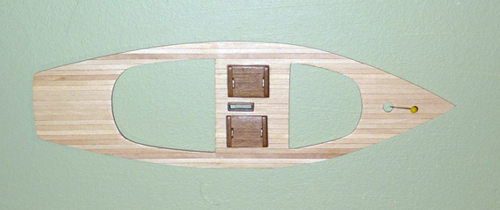
Next Update The MBLS has been a fun build and I have enjoyed reading and researching the history of working boats. Now that I am close to finishing the hull some of the ‘oops’ are starting to show up. I’ll split this into a few posts. (Mother Nature is about to put on one of her “Light Show”, so I might lose power in between posts.) 07 05 2016 Looking for these photos....... F2 Bulkhead Next time, I’ll line the top of this bulkhead with walnut to keep it from becoming deformed. The starboard side ended up being significantly shorter. Also, I should have done more work on the hatch door before gluing it to the keel and then complete most of it after adding the deck. The hatch rails need more work. Fish Well Hatches I like these fish well hatches, but the obvious is they are way too big. Next time I’ll stay with the original size and make them flush fitted. The blue thread is to prevent losing them! (Edited 11/26/2014 to add back photos....)
-
My original question asked why CA glue goes bad and Augie responded – It happens! I’m addicted to breathing without a respirator for the rest of my natural born life. Thanks, but NO THANKS to using CA accelerators. Keep your fumes to yourself.
-
Thanks Augie. The obvious is my bottle of CA is older than I thought! Lesson learned! Going forward, I’ll stick with one ounce bottles, purchase from vendors/stores that should have a high inventory turnover ratio and write the date on the bottle when opened. Thanks again! Dee Dee (Edited to correct spelling ect.)
-
Does CA glue have a ‘shelf life’? Specifically, AFTER the bottle has been opened? Reason I ask, is for the past few months, I’ve been using a bottle of ‘Mercury Adhesives M300M’, orange label, medium viscosity, 2 ounce bottle. Starting yesterday, this glue will not ‘set up’ and 'do its job.' Today, I squirted some on to a piece of cardboard and two hours later, it was still sticky and ‘gloopy’ (a technical term.) There’s about 15% left in the bottle (bottom of the label.) I’m positive I did not contaminate the glue and always keep the cap on the bottle. With just 15% left in the bottle, is there too much air in the bottle? The obvious fix is going forward I’ll stick with the one ounce bottles. But I’m just curious why this happened. ……Yes, I know what ‘they’ say about the curious cat. It sounds like I use a lot of CA, but I don’t. When I do use it, I squirt some onto cardboard and then apply with the tip of a bamboo skewer. More than half of what goes onto the cardboard is still on the cardboard, no cross contamination as one side is for CA and the other for Elmer’s and separate bamboo skewers for each. Thanks Dee Dee
-
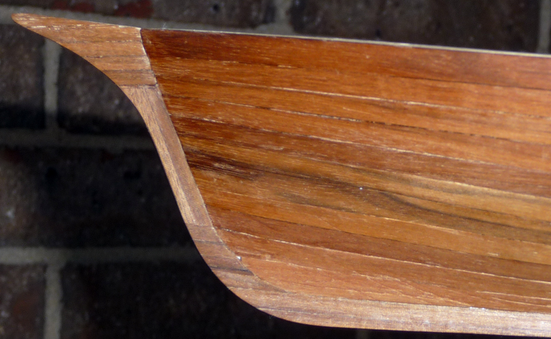
Planking the port side is done and it turned out much better. I took extra time to make sure the top edge of each plank was beveled to get a tight fit. Then each plank was glued in two inch segments (bulkhead to bulkhead.) It was a slow process, but the results were well worth it. I pushed my luck using just 11 planks. At the widest point I had just 1/8” fudge factor. On the starboard side I had to fill in numerous ‘gaps’, but on the port side I only had to use two on the last plank added. ‘Next Time’ I’ll add one more plank for a total of 12 planks / side. I veneered the keel with 1/64” x 1/8” walnut (Looking for this photo....) ‘Next Time’ the cutwater will be added after I’m done planking. The first planking will land on a false flat bulkhead and the second planking will land on the keel. This will give a clean line for the cutwater. (I’ll add a drawing.) Close up of starboard bow Close up of port bow A photo with the fish well hatches What I learned: While walnut is a difficult wood to work with, if I take my time, it is possible to get good results. I need to do more planning with the number of strips needed to plank a side – don’t cut it so close How to prepare the bow / keel for planking I just received ‘Next Time’, so I will be doing some planning, adjusting the print and make the false flat bulkhead. Also, it will have a real, working centerboard. Well, that's it for now. Thanks again for stopping by. Suggestions are always welcome. Dee Dee (Edited 11/26/2014 to add back photos....) (Edited 4/09/15 to add back photos)
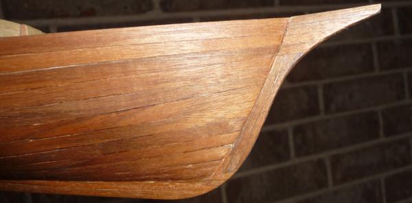

-
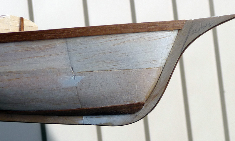
So this is the place where I dive into the ‘dark side’ of modeling…. I was not going to post again until both sides were planked, but I just finished the starboard side and it turned out OK! I started with a full plank at the top and a full plank at the bottom – I think that’s called the gardboard plank. Did some measuring and decided to use nine 1/4" x 1/32” planks for a total of 11 planks. Next I marked off the hull at the bulkheads using the ‘fan’ and started to plank away! As for why am I using walnut for planking – I had a momentary lapse of sanity, but I’m better now and the doctor said I should be off the meds in a month or two… .. I was at the local hobby shop, when I spied a stash of walnut that appeared to be orphaned, so I purchased a stash and bought it home with me. I had no idea where I was going to use this, until I started this build. Next time, walnut will be great for deck fittings, but I’ll use a different wood for the planking. After I did a few planks, I figured out that the first planking can be done with strips. I’ll make a drawing and add it later the small changes needed. This would eliminate the bow blocks, the cutwater can be added later, giving a much cleaner bow. The walnut frequently splintered resulting in some ‘gaps.’ But these were filled in using the 1/64” strips. Next I scraped and sanded the hull and wiped it down with a damp cloth. While still damp, I burnished the hull with a hardwood block. There’s a couple of glue marks that I’ll need to remove. Also, there are a few gaps that I will pack with thread and watered down glue. The transom was veneered in 1/64” walnut strips. When the port side is done, I’ll veneer the keel and cutwater with more of the 1/64” walnut strips. Also, Midwest keels are made from basswood and the keel is going to get nicked / deformed during the build. So before I started this build, I glued a 1/64” strip of walnut to the edge of the keel and cutwater to keep its shape. I highly recommend! The first two planks The transom veneered with 1/64” strips What I learned: Yes it is possible to do the first planking with strips. I need to make a drawing so I remember how to do it next time. Be careful when planking over the balsa first layer – balsa WILL bend very easily! Walnut is nice – but I’ll keep it to deck furniture. Not sure if I should have veneered the keel before planking, so, on the port side I’ll veneer the keel first and find out! Since this boat does not have shrouds, I could have added a rub rail below the top plank. Well, that's it for now. Thanks again for stopping by. Suggestions are always welcome. Dee Dee (Edited on 5/27/2013 to add photos back) (Edited on 11/26/2014 to add photos back) (Edited on 4/09/15 to add photos back for the third time)

-
Bob, I’ve seen this photo and read about Ranger. Since you are the closest, I think you need to take a ‘road trip’ to the Penobscot Maritime Museum. If needed, Keith & I will write you a ‘note’. FWIW, before I saw Bob’s photo of his rudder (page one) my plan for attaching the tiller to the rudder was beyond wacky! Bob’s picture bought me back to reality. As for the rudder post – I think it could go either way. I’m thinking it depends on how the rudder is secured to keep it from ‘floating up’ and off the keel mount. Another reason why a road trip is in order! ~~~ The first planking is done. I soaked the planks by wrapping them in a few paper towels, dousing them in water and into the microwave for a minute. When done, they were wrapped in tin foil and a thick towel for five minutes. This worked great, except on one piece I used ‘heavy duty’ paper towels and that left an ‘impression’ on the wood. Ooops! I'm happy with the snug fit of the cockpit floor and the hull. Per the blueprint, the cockpit floor is 18” below the deck and the benches are maybe 9” high. Next time, I’ll drop the height of the cockpit floor. I could have done a better job with beveling the top plank – there are a couple of thin spots and pin holes. If I was not doing a second planking, I would definitely take these off and start over again. Since the second planking will be walnut, the rudder will look sort of ‘weird’, so I am remaking the rudder and tiller. I was playing around with this rudder assembly and decided the new tiller will be closer to print. The original tiller does not ‘clear the deck’ and would reduce the maneuverability of the boat. The blank is made, but will wait until the second planking is done before shaping it. Next up is gluing and carving the bow blocks. After that, the fun begins with the planking! Thanks for stopping by - Any comments suggestions are welcome. Dee Dee (Edited 5/27/2013 to add back pictures) (Edited 11/26/2014 to add back pictures) .
-
Børge Your Dragon build is an inspiration! Thank you for reposting! Dee Dee
-
Harvey, Thanks for chiming in on the book info for Pete. Pete, The book Harvey referred to is the one! This book is a fascinating read and filled with detail. You can find it on Amazon (5 star reviews) and also on eBay. Check out the reviews on Amazon: http://www.amazon.com/American-Small-Sailing-Craft-Construction/dp/0393031438/ref=sr_1_1?ie=UTF8&qid=1364258059&sr=8-1&keywords=chapelle+American+small+sailing+craft David, Thanks for the info on the gesso and sliders. I’ll pick up some gesso and experiment. I’ll also experiment with layering for the window covers. Thanks again! Popeye, Thanks for stopping by. I have been struggling with the planking. I decided to use the kit supplied planks as the first layer and walnut strips for the second layer. Three of 4 planks are done and I was close to abandoning the idea of a second layer. But I went back to the prints from the Corel Sloop that I just built and I think I figured it out. The second planking has no place to ‘land’, so the cutwater needs to be added before doing the second planking. I taped the cutwater on and dry fitted a couple of strips and that works! So now I need to decide to remake or veneer the cutwater and rudder / tiller! Great point about the rudder being the same thickness as the stem post / keel. The kit rudder is only 1/16” thick while the keel is 1/8” thick. Keith, I’m having a lot of fun building this boat. I took a bit of ‘artistic license’ with the shape of my tiller. Measuring the tiller on the drawing, it starts at 3” at the rudder post and tapers down to 1½”. This is a working boat and IMHO that is just too thin. In height, my tiller starts at 4” and tapers to just over 2”. I did not make any structural changes. The difference is I have already faired the bottom of the transom and hexnut has not. Hexnut’s hull will look the same after he fairs the transom. I reposted the two pictures together for easy comparison. Follow the line of the keel strip and you will see what hexnut’s hull will look like. I appreciate all who stop by to take a look. I appreciate any and all help / suggestions / guidance. Dee Dee Dee Dee (Edited on 5/27/2013 to add back photos)
-
David, Thanks for reposting your build - I really like you color scheme. Do you reccomend using gesso before painting? Would it be possible to post a 'close up' on the cabin sliding window covers? I plan to add these to my current build and would like to see how you made yours. Thanks again! Dee Dee
-
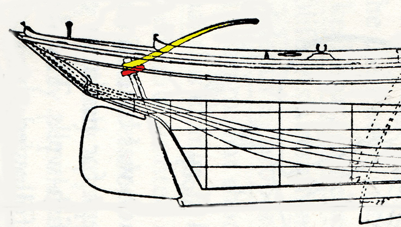
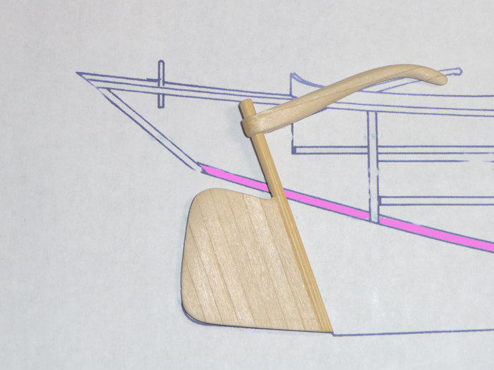
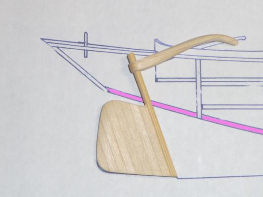
Back from Colorado Springs and it was a great to meet up with colleagues in a relaxed environment! The rudder, tiller and collar are done and I’m happy. The tiller was carved from a block of 1/8” basswood stock glued up. The collar was made from a thin strip of paper cut from a dollar bill and made just like a mast hoop, glued up with CA then sanded smooth and to thickness. And as expected, I broke off a section of the chine, but that was easily fixed. A picture is worth a thousand words… These three photos compare my rudder / tiller assembly against Midwest blue prints and Chapelle’s drawing. Yep! I Need to add wood filler to the keel. I did a sloppy job on sandwiching the keel for the rudder post. Next time, I’ll make the ‘keel sandwich’ from one piece of wood on each side (shown in YELLOW). The PINK is the keel strip and the GREEN area will be cut away for the tiller and collar. Compare Midwest’s blue print to Chapelle’s drawing. Love them or hate them, there is no denying that Midwest has done a great job to preserve our history. Dee Dee (Edited on 5/27/2013 to add back pictures) (Edited on 11/26/2014 to add back pictures)
- 89 replies
-
- 1
-
-
- muscongus bay lobster smack
- midwest products
- (and 1 more)
-
Bob, - Our posts crossed! You are right about rudder retention – it’s very simple. As for the ‘knife and comb’, I think this is correct, if not hope someone will correct. I’m borrowing these two pics from hamilton’s build of Pinky Glad Tidings. The knife fits into a slot on the comb to lock the tiller. Have a GREAT weekend! Dee Dee That's the ‘knife’ hanging off the tiller And that's the 'comb' on the deck
-
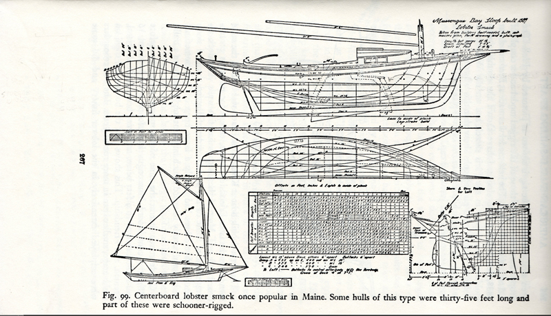
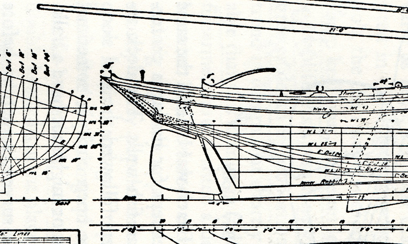
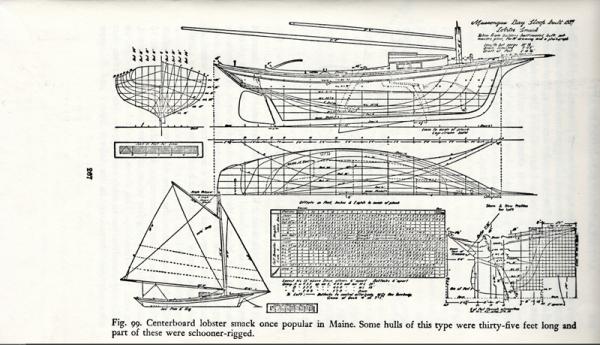
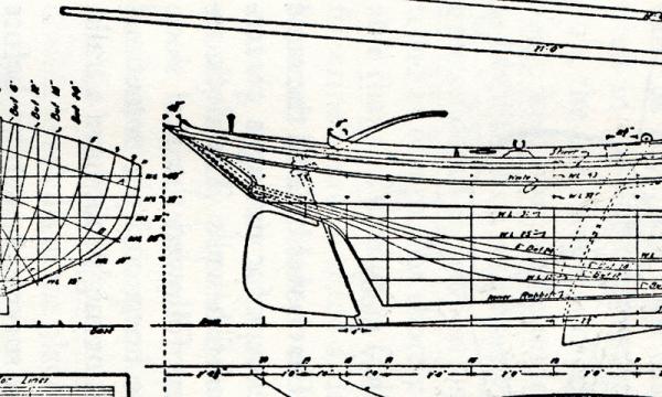
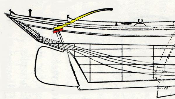
Mario! Yes, that rudder! I really like the color and finish on that beautiful model! Michael! I really appreciate you stopping by and checking in! Your Bristol Pilot Cutter build is inspiring! Buck, Your whale boat is stunning! A 1927 Martin D-18 – Wow! I love my 1970 Martin D-18S. Harvey, Thanks for the input on the planking. I think you’re right, caravel/traditional planking would probably be better (but the lap planking would look really kewl, maybe on the Flattie.) I’ve built the Corel Sloup which has a similar shape and each plank had to be beveled to get a tight fit going around the chine. ~~~~ I’ve been dinking with the line drawing Chapells’ book and I think I have a plan to install the rudder as if the model was life size. This is the line drawing of the MBS from Chapelles’ book – Even with a magnifying glass, detail is difficult to see. I scanned the page and zoomed in on the rudder area. Then removed excess lines, connected some of the dots and added a bit of color for clarity and VOILA! My interpretation of this drawing! It appears a ‘collar’ (in red) was used to secure the rudder and the top of the rudder post butts up against the underside of the deck. On the unaltered kit keel, the slot for the tiller is at the same angle as the collar which now makes sense. Here’s my ‘Game Plan’ – A new rudder was made from 1/8” square basswood strip and a bamboo skewer for the post. But will be remade once the hull is planked so the lines will follow the hull better. The opening for the rudder post is being enlarged similar to how Bob did his in the photo above. In the pic above, (top green arrow) the space behind the rudder post will be a bit over 1/16” to accommodate a ‘life size’ collar 1½” thick (drawn in red). The bottom of this opening will be at 90* to the rudder post. Yep! I should have done this before I added the chine and deck! Oh well! The bottom green arrow shows the section of the keel that will be replaced with a longer section to form the keel extension which the rudder sits on. But this will have to wait as ‘PLAY TIME’ is over until sometime next week. In the AM I’m off to Colorado Springs for a USA Cycling Officials Summit Meeting Hope everyone has a great weekend! Dee Dee (Edited on 5/27/13 to add pictures back in.) (Edited on 11/26/2014 to add pictures back - again!) (Edited on 4/9/15 to add pictures back - for the third time) .
-
Mario, your Smack build was my inspiration! And yes, Chapelle’s “American Small Sailing Craft" book priceless! Wayne – Adding detail is the fun of Midwest kits. Keith – You are the eagle eye! Yes, the well covers are 1/4" wider and 1/4" longer (1/8" on each side). Hers’s a pic of the underside, that solid piece of wood is the original well cover. Buck – Thanks for looking Pete – Yes, the deck planks are 1/8" x 1/32” basswood strips, sanded to half the thickness, clear coated with Krylon Matte Finish Spray, (craft specific & available at Michaels), then buffed the finish with a paper towel. My first wood boat was also the Sakonnet daysailer – that little model taught me a lot! As for the blueprints being compatible, the Midwest Muscongus Lobster Smack kit is for the centerboard smack which went out of favor in the mid 1890’s and quickly replaced with a keel hull design. Per the info on the prints, Lucille was built in 1905, so I think these prints are for a keel hull boat. Same thoughts with the Satellite which was built in 1916. You will definitely enjoy building this boat! Bob – I dithered about too with the position of the well covers, until I started thinking in “life size”. Per the blueprint, the fish would be two feet (life size) from the cockpit and 2” from the cabin door: that would make it difficult to reach or see into the fish wells from the cockpit and awkward footing at the cabin door. For the rudder, I modified the keel by cutting out a 1/8” strip in the keel (before adding the bulkheads), then sandwiched the keel back together with two layers of wood (grain running 90*). The picture on page 268 of Chapelles' book shows the rudder rests/sits on a keel extension and no gudgeons used. I’m going to cut out a section of the keel and add a strip to form a keel extension. My dilemma is how (in life size) would I install / remove the rudder when the boat is in dry dock. The obvious is lift the rudder post into the opening, then drop the pin into the keel extension. But when the boat is in the water, I need some means to prevent the rudder from lifting up / or floating off the keel pin. Does that make sense? To think this through, I need to make the keel first. Thanks all for looking and your comments! Dee Dee (Edited on 5/27/2013 to add back photos) (Edited on 11/29/2014 to add back photos) (Edited on 4/09/15 to add back photos for the third and last time)
-
Bob, Love your drawing! Is this your drawing? Your build is looking great! Hope this helps. 1. Caprail & planking – I added planking, but my planking is horizontal. I’ll also be adding a cap rail. 2. Filler? Open Gap? Bilge Pump? See the photo and notes in my build log about the cockpit floor. Essentially, the floor is too small, I added width to my floor, but a lot of it was sanded off when fairing the frame 3. Eliminate Seating? Can’t find anything definitive, however, I’m inclined to believe these boats DID have seating since you can’t sit on the deck. Also, the lobster traps (if used) would sit on the seats while baiting. 4. Traveller, nailed to deck w/feet. The traveler would threaded on both ends, the ends go down through the deck, another piece of lumber and then bolted with a wide washer. The purpose of the additional piece of lumber is to distribute the load that the mainsail puts on the traveler. If the traveler was just nailed to the deck, it would rip out. I’m going to be adding feet / trim to my traveler. 5. Lobster wells. The drawing on page 267 show the centerboard trunk is correct and it also shows the handle. I like your idea of hinged doors, but they might be impractical since this is a no frill work boat. I moved my wells closer to the cockpit. As for ergonomics of the fish wells, these boats are long before ‘safety in the work place.’ 6. Centerboard hook – this is right, the hook is attached to a short length of chain which is attached to the centerboard 7. Companion way. The door is one piece, slides up and out and stored in the cabin. At full size, this door is 15" - 18" high 8. These centerboard boats did not have shouds (see page 266, second to last line.) Shouds were added on the keeled boats. 9. Stovepipe – It appears the stovepipe was not on this boat, but was added to the Friendship sloop. Check out the windows on the drawing on page 267 – The windows appears to have a sliding cover and your drawing also appears to have a sliding cover. On your drawing, it looks like the bow spit would pivot on the Sampson post, which is common on European fishing boats Again, love your drawing! Dee Dee
- 86 replies
-
- 1
-
-
- muscongus bay lobster smack
- Midwest Products
- (and 1 more)
-
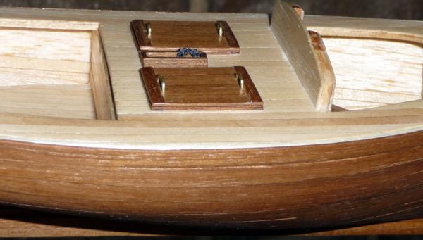
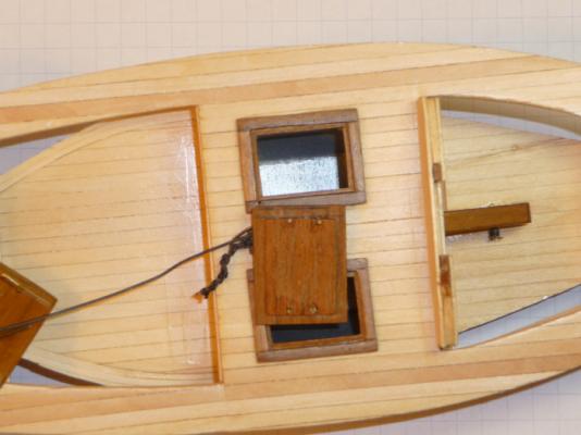
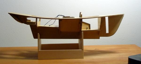
Once upon a time, this build log contained a lot of high quality photos showing lots of detail. But many photos have gone repeatedly missing - The photos in this first post have gone missing / been replaced three times. It's more than just a glitch. I try to keep up with restoring the photos...... There are lots of photos on pages 3 and 5! Most of the build photos, I also posted on Picasa, so if you have a specific question, please send me an IM and I will send you the link to Picasa. Midwest models are amazingly close to the drawings in Chappelle’s book, they’re fun to build and learning. Following Mario’s lead, I’m adding lots of detail to my Muscongus Bay Lobster Smack build and having fun! I’ve added the fish wells, a cabin with floor and centerboard trunk. The rudder will also be a working rudder. At this point, I checked the instruction book to see just how far along I was – It was a shock when I realized I was only on step 17. These fish wells are too deep and the cabin floor should have been lower. This would have given the space to add the bunk on the port side. I added a second layer of decking and fish well covers. The original deck consisted of three pieces of wood: the deck and two well covers. This deck consists of 68 pieces of wood. There will be full access to the cabin. You can just barely see the centerboard hinge pin at the base of the trunk. Also added a ‘step’ for access. If the floor was lower, I could have added the bunk on the port side. It was fun adding the fish wells, centerboard trunk access and the covers. The covers will be held secure with a piece of chain. These wells are much too deep. I painted the wells with silver paint to simulate tin lining. For the centerboard trunk, I carved away some of the keel, then added some sides and painted it black. I attached an eye hook for the rope and I’ll attach the handle. In almost all Midwest sailboats, the cockpit floor is too small. First I added planking to the kit floor, then added width to the kit floor, but had to sand a lot off when fairing the frame. Now this cockpit floor will fit tight against the sides of the hull. This brings me current. At this point in the build, the kit calls for ~20 individual pieces of wood. So far, I think I am close to 180 individual pieces of wood used in this build. I need to install the rudder and tiller before finishing the hull. I think I should have done this before I added the deck. As for the hull, I’m thinking about doing the hull in lap-strake planks. Any suggestions would be appreciated.. Thanks for looking, your thoughts, suggestions are always appreciated Dee Dee (Edited on 5/27/13 to add photos again) (Edited on 9/07/13 to add 'SMALL' to title) (Edited on 11/26/14 to add back photos - again!) (Edited on 4/09/15 to add back photos for the third time) .
- 89 replies
-
- 2
-
-
- muscongus bay lobster smack
- midwest products
- (and 1 more)
-
Hi Bob, I’m also working on a Muscongus Smack and am at the exact same spot in the build. I’m also using Chappelle’s book and added a working rudder, centerboard trunk deck access, fish wells with lids, cabin with centerboard tank. I might have made a mistake by not adding the rudder before the deck, but I think I know how to fix that. I also added a floor in the cabin and widened the cockpit floor. Midwest boats are a great way to learn and fun to add detail. Mario built numerous Midwest boats, here are some links to his builds: Moscongus Lobster Smack http://www.modelshipbuilder.com/e107_plugins/forum/forum_viewtopic.php?3900 Chesapeake Flattie http://modelshipworld.com/index.php?/topic/988-chesapeake-bay-flattie-intarsia-124telemancompleted/ I’ll get some pics of my build posted later today. Dee Dee (Edited to update link to Chesapeake Flattie)
- 86 replies
-
- 2
-
-
- muscongus bay lobster smack
- Midwest Products
- (and 1 more)