
HOLIDAY DONATION DRIVE - SUPPORT MSW - DO YOUR PART TO KEEP THIS GREAT FORUM GOING! (89 donations so far out of 49,000 members - C'mon guys!)
×


kmart
-
Posts
195 -
Joined
-
Last visited
Content Type
Profiles
Forums
Gallery
Events
Everything posted by kmart
-
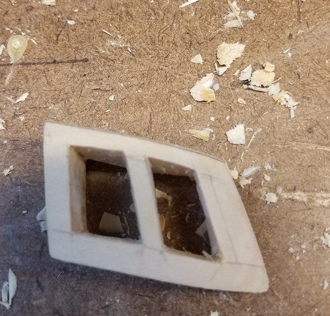
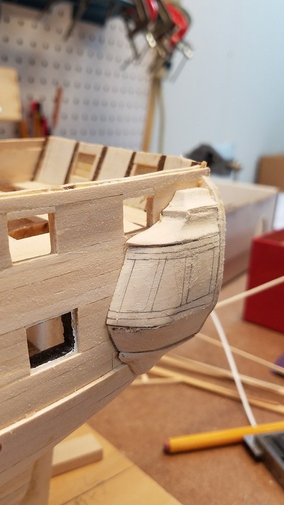
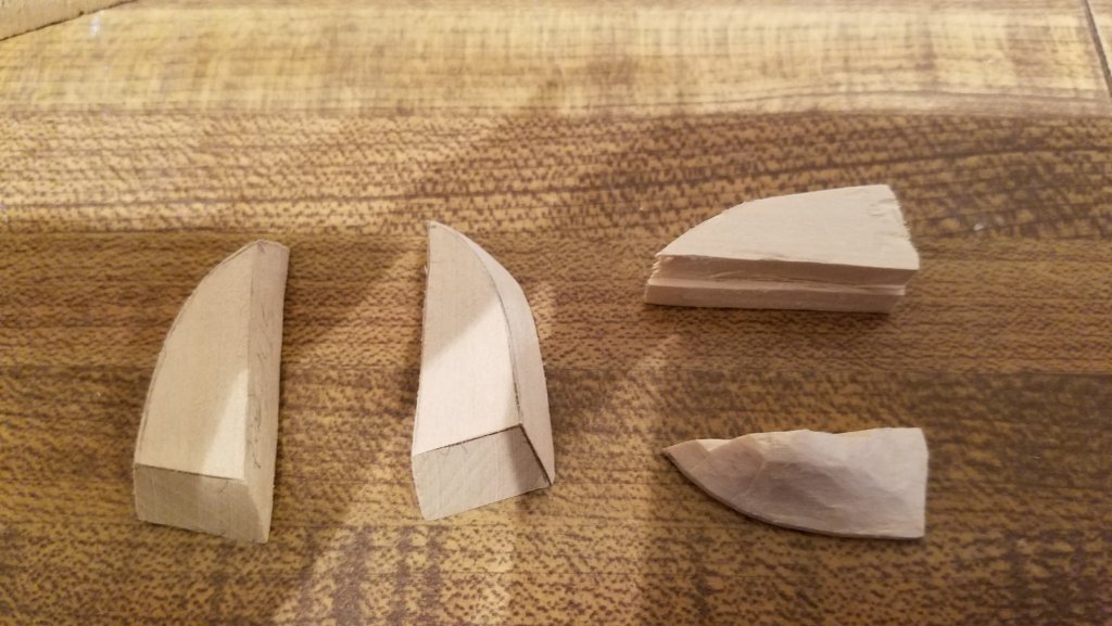
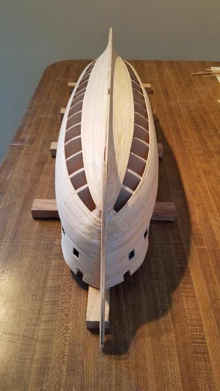
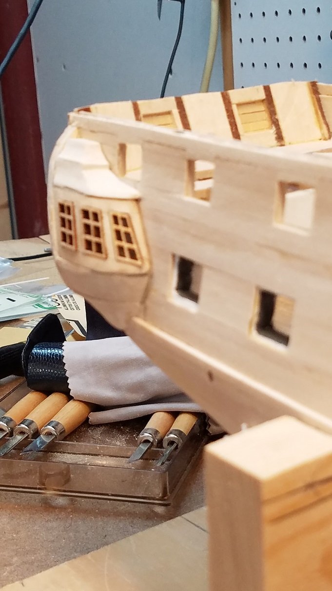
Jonathan and GrandpaPhil... Thanks for the feedback. The more I'm looking at it, the more I like it. Once cleaned up and detailed it will work. So onto my progress. slow but moving forward. I needed to prep the quarter gallery windows. so after tracing out where the windows will go... I drilled a bunch of holes in the block Then carefully carved, cut out the openings From the backside both Quarters with windows roughed in Set on the Hull And the port side Once cleaned up and painted.. I think they will come out looking decent. I cant believe how long a 4 small block took me to make. (days) That's it for today. And Happy Veterans Day for all of you who have served. We owe you more than we could ever possibly repay! Thank you.
.jpg.f4b76dde7364b9015dd5142a041ed532.jpg)
.jpg.2c64e47e572b90456e4b0f7f0a72c59a.jpg)
.jpg.3eb93cd3f50881a7ea5709ca4728d72f.jpg)
.jpg.43a13e5a4363bb96c31d9b3c8b910739.jpg)
.jpg.dbaa9e0fed115be0318edc6aef6a376c.jpg)
.thumb.jpg.21d0359fd8a8d550bc5966e5e01c6521.jpg)
-
I just went and checked my picture library. ... This is how Connie's roof currently looks today. This is in line with the simpler version of the roof. Now the fancier version the roof extends higher up and has another white trim line in the middle. So my last attempt isn't as far off shape wise as i thought. hmmmm
-
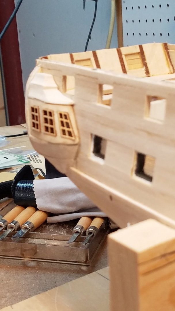
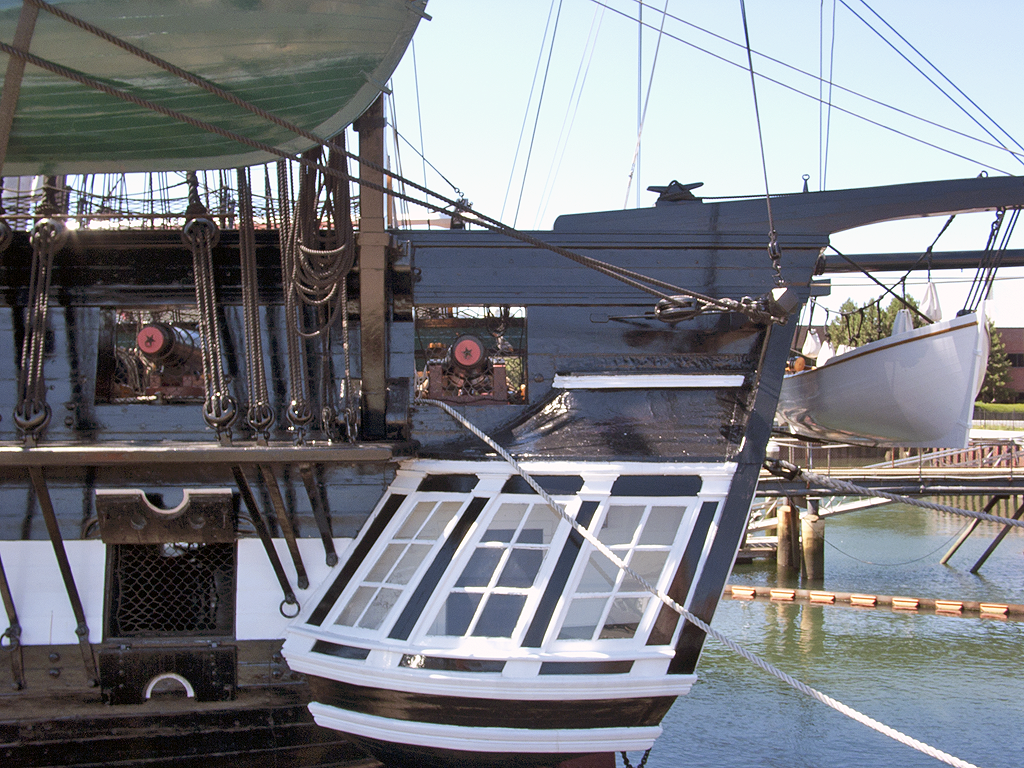
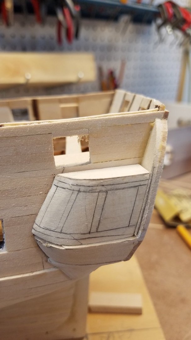
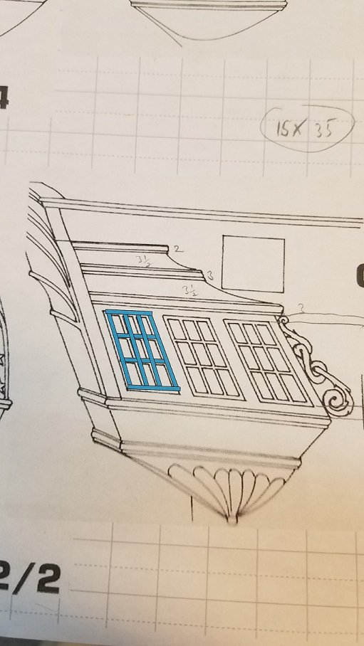
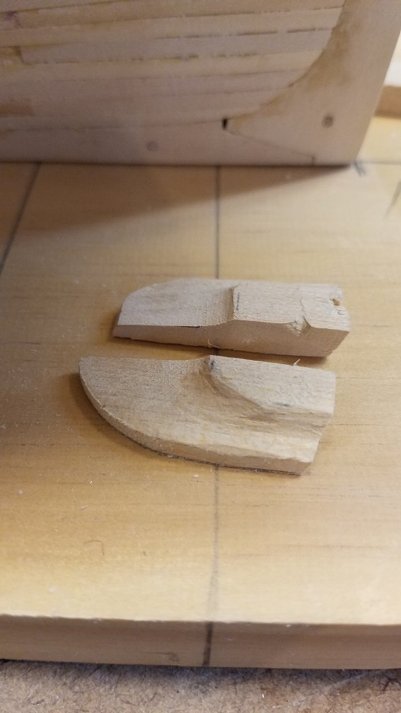
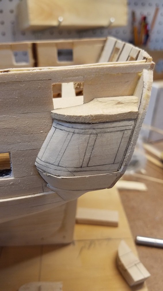
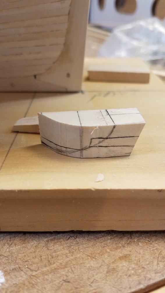
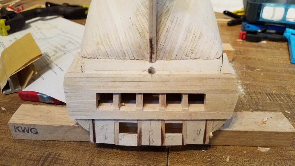
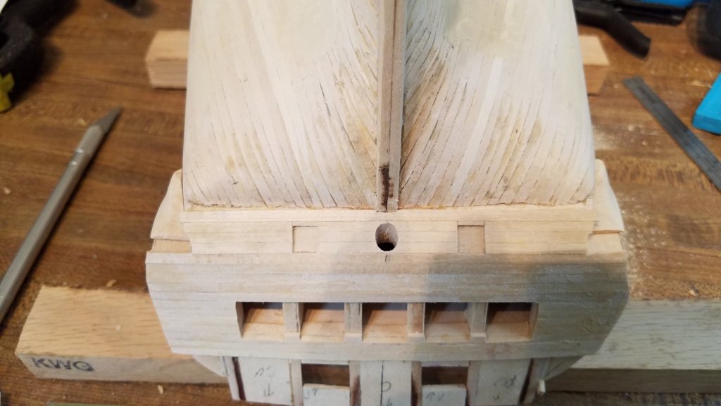
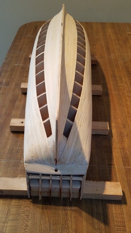
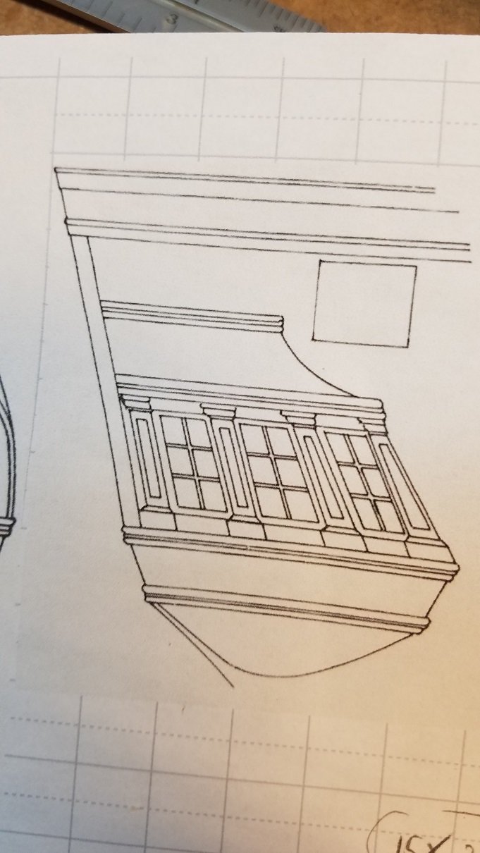
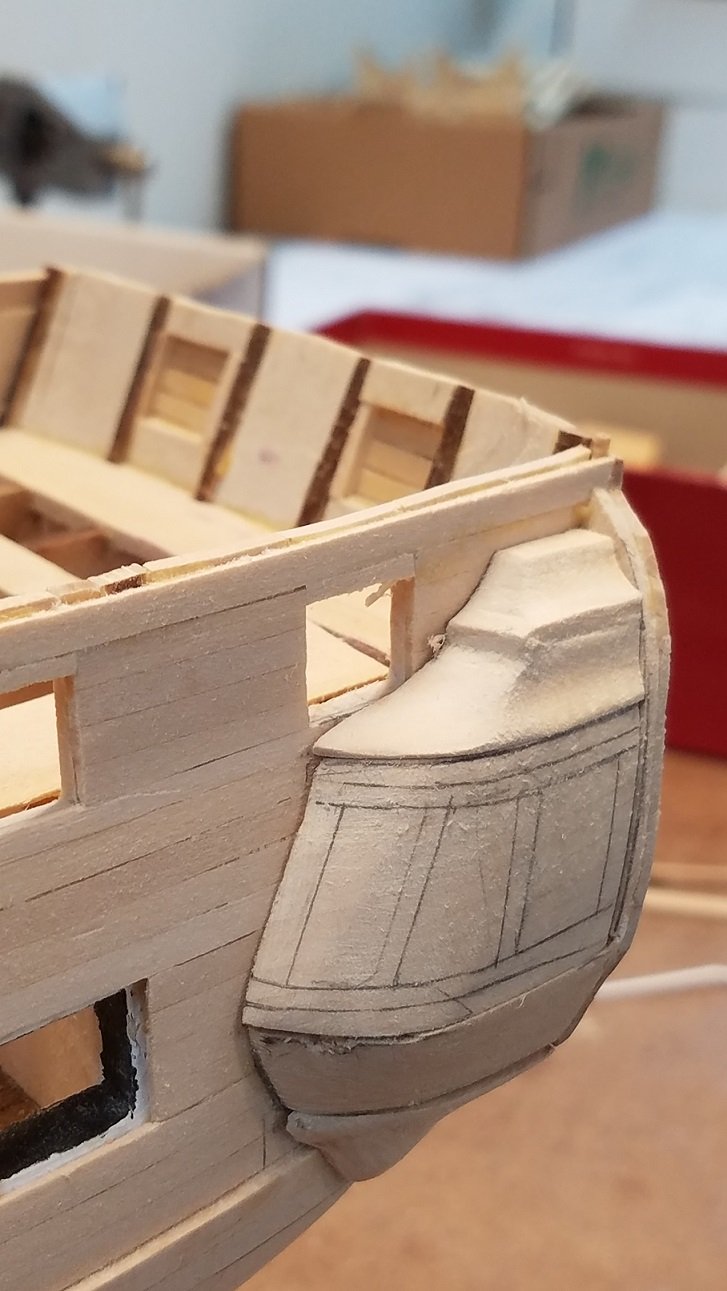
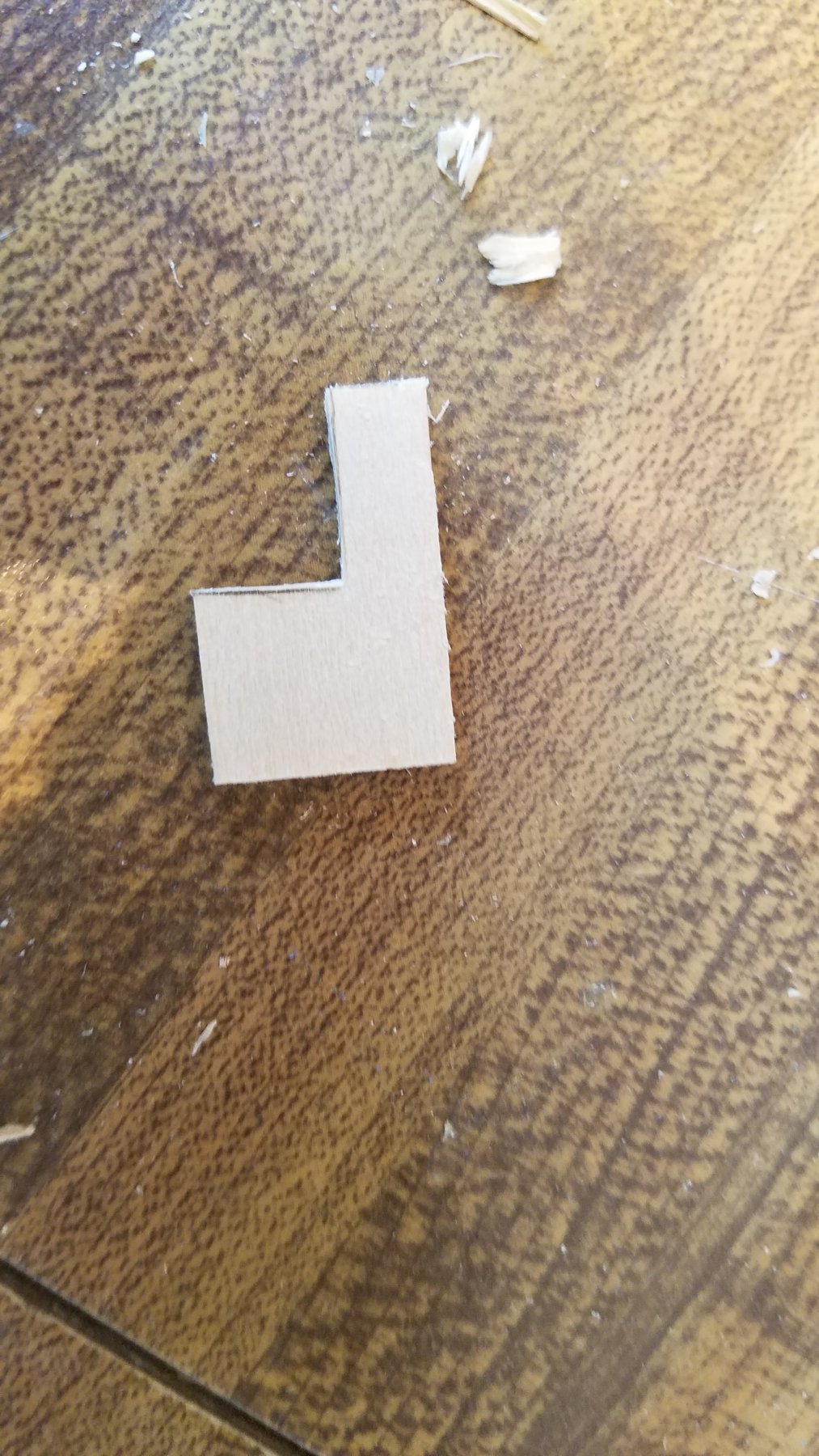
So,,,last spring, when I left off, I had started working on the quarter galleries.. I had just completed the lower piece, and the decorative piece underneath it. Next After several attempts I made the main part where the windows will go. I made out of a solid block. The challenge was fitting the three surfaces properly .. All of them angled and not square with one another. Bottom, inner side towards the hull and then the back towards the aft. After several attempts, I got the block to fit. After that, shaping the front curved side was fairly straight forward. Using the kits window frames, I traced in where the windows will go. leaving 2 mm under and over the window frames, Then another 3 mm for the trim. You can see that marked up on the block Next up comes the Roof. I have two options with this. The easier one... or the harder version... I'll give you 3 guesses on which one I chose to attempt. Attempt #1 : i thought I could model in two pieces to make up the roof. First piece breaking of the trim in the middle So attempt #1 failed. I didn't like the looks, and the top of the roof was not sized to have the second layer. Attempt #2, and #3, all failed as well. I cant believe how much time I've wasted on making 2 little pieces of wood. Grrrrrrrrr Now onto attempt #4 came out a bit better: This attempt is with a single piece. Because doing one big complex block couldn't possibly be harder than doing smaller , simpler shaped pieces ) Laying out the cuts to make on the block After cutting and rough shaping It has potential.. But it kinda looks more like a shoe or sneaker that a fancy roof. Both at the bottom and then at the flat selection in the middle , I'll put a trim piece. That might make it look better. But I'm not convinced yet. Still considering to another attempt. This is a really hard part to make. Really testing and frustrating me. Thoughts , opinions.... look good enough once cleaned up and painted... or start over.? FYI for the main piece.. the plan is to cut out where the windows will go. Then use jig saw to cut away the inside of the block. That will leave the outer wall... say 2 mm thick, with all the proper curves and fitting and window frames as one piece. ( I still think the roof looks like a sneaker!) That's it for now. And please comment on the roof. keep the roof or toss it and try again.


-
You build is looking good. Off to a great start. Will be following you progress! K
-
Hello all, Sooo sailing season (real sailing as apposed to model sailing :-)) is wrapping up in the next few weeks here in New England. Hoping to get a few more days on the water before hauling her out. Then it will be back to work on the Connie after the summer hiatus. I already started cleaning up the basement workshop to start getting my brain back into modeling mode And thinking about where I left off . My goal for this winter modeling season.... is : Finish the hull Finish the stern windows/ details/ quarter galleries Paint the hull Detail the main gun deck And just maybe get the spar deck planking in At my speed of modeling that's ambitious. but that's the goal. Especially as I'm trying to do a respectable job and up the quality of my Connie build over my past builds as apposed to fast... Should start having real updates and (modeling) pics in the next few weeks. K
-
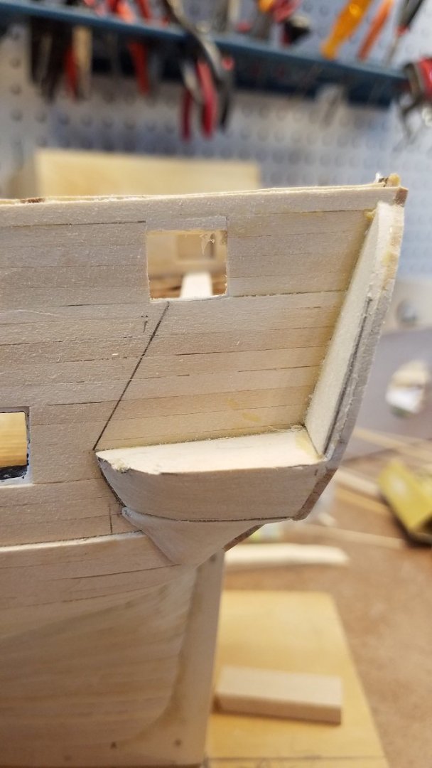
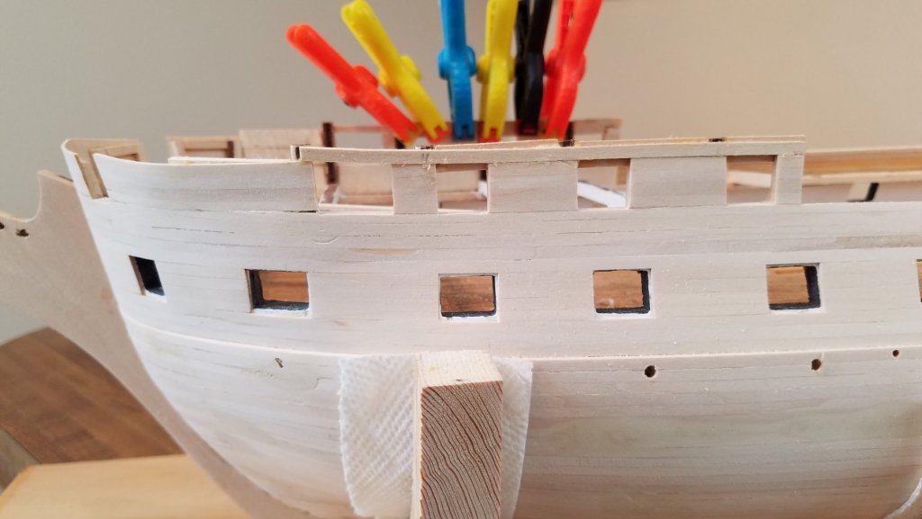
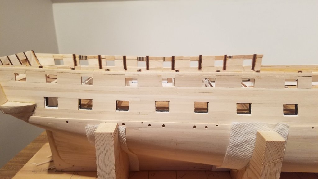
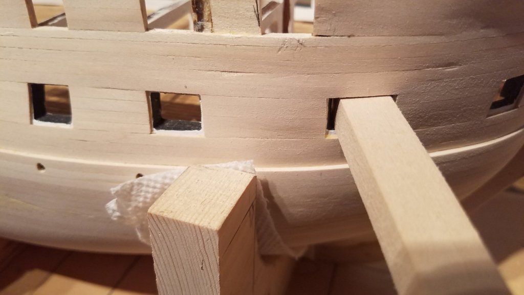
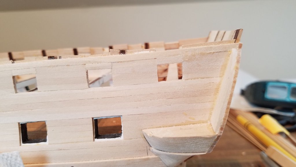
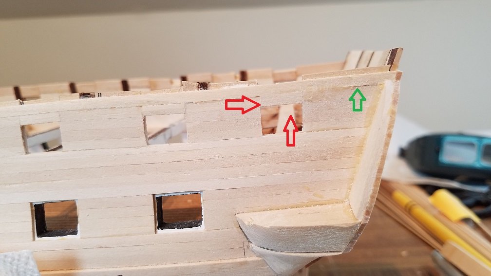
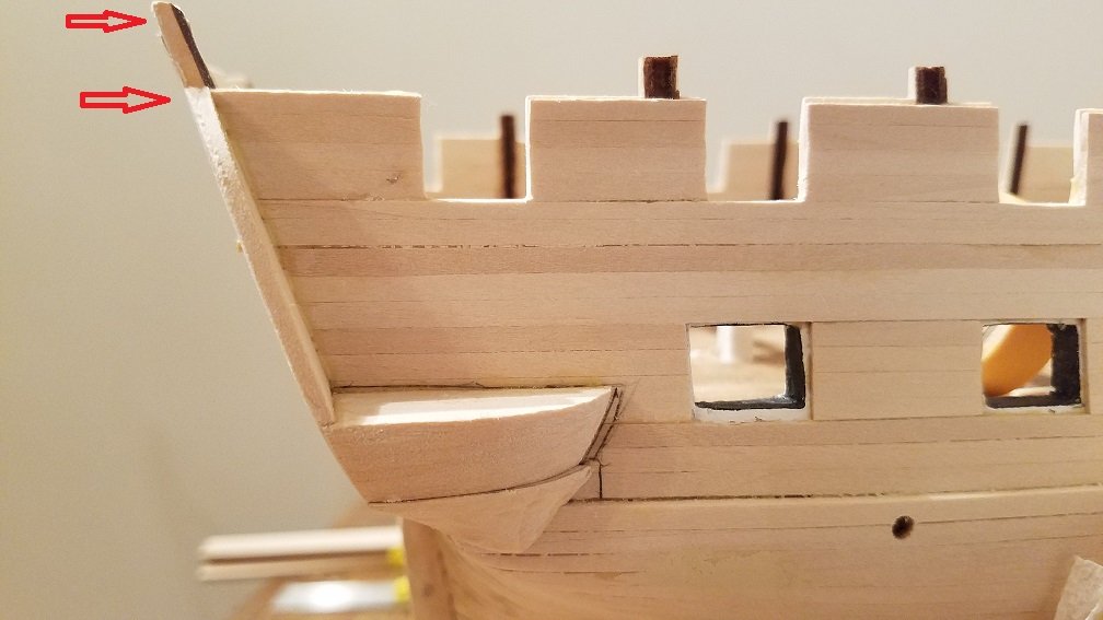
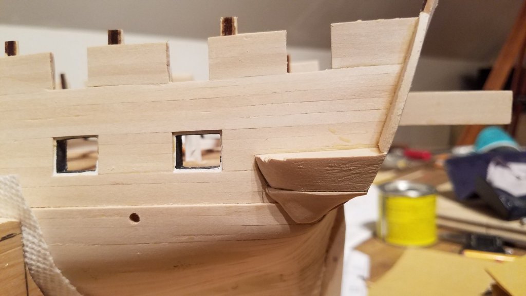
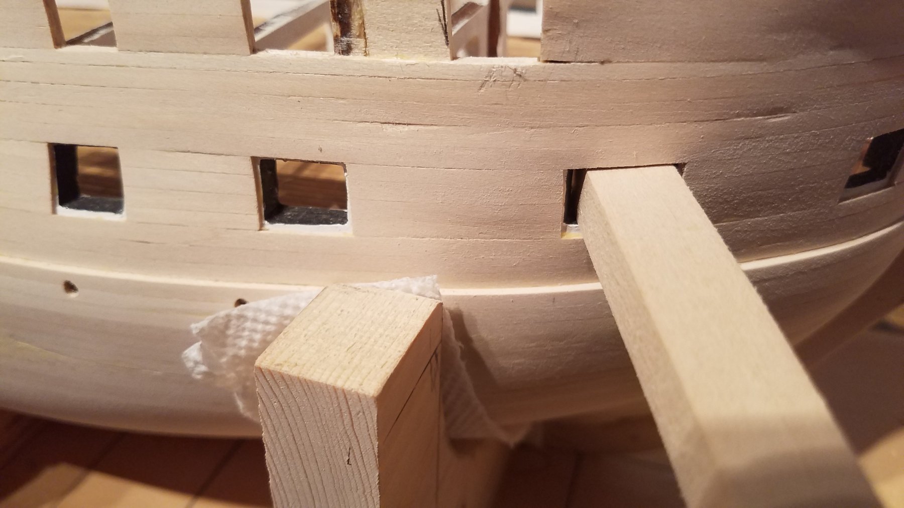
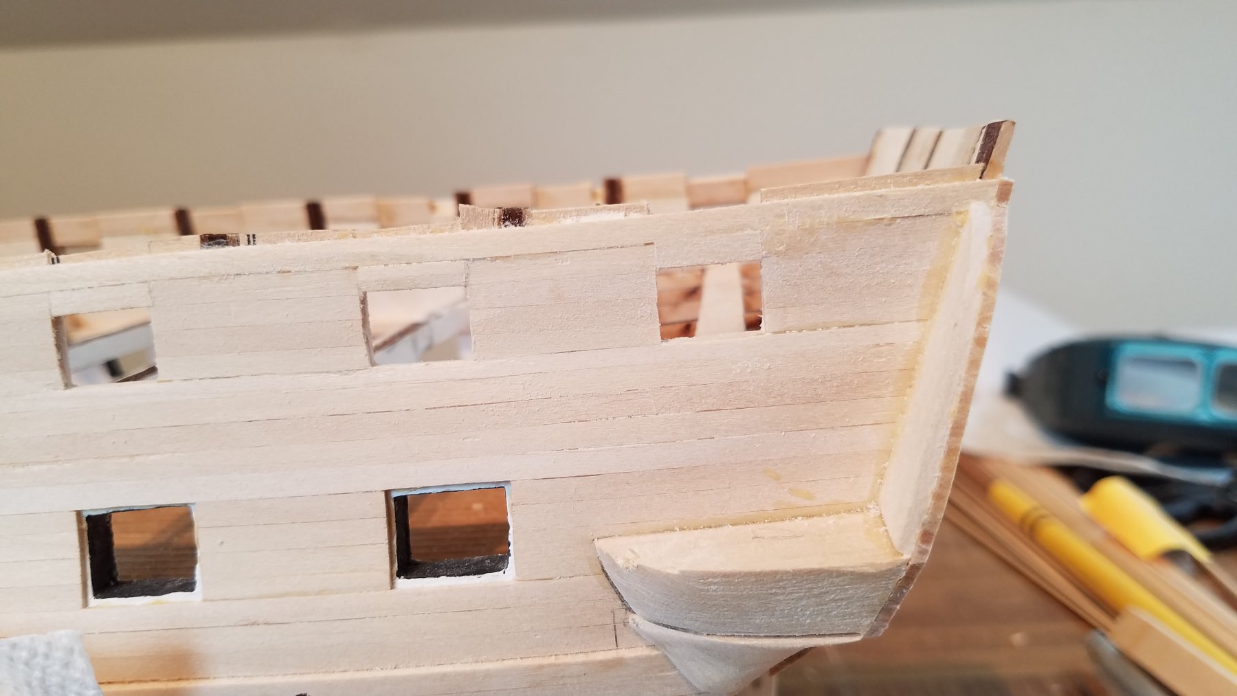
Another view of the aft extra plank in place Screw up #3 This was done prior.. I just noticed it now. Well since I'm adding the extra plank aft .. it needs to go all the way around so I'm making same update at the bow. Look at the first gun-port... that's closet to the bow. That's Not actually a gun-port.. its where the anchor gets stored. Notice its a larger size than the gun-port. That's correct per the current 2019 version of the ship. But all the Corne paintings and AOS pictures show it as the same size as a normal gun-port.... So not correct for 1812. Plus I really didn't like how it looks. not symmetrical with the rest of the ports... Soo demolishing time. Made a new backing piece Glued in place Next session I'll plank it over.. Screw up #4 Also just noticed today. Waaay back when I was framing the main deck gun-ports. I was so pleased with myself for my framing method and my jig for perfectly square gun-ports... Well As you can clearly see... quite a large gap. This is for both gun-ports on both sides. The way I framed them two at at a time port starboard... worked great for rest of the ship. Because of the steep curvature at the bow, If I run the jig all the way through both ports.. its square and proper sized, but because of the curvature of the hull, if I put the jig in at 90 to the hull... the ports too wide. Fortunately is just the one pair that suffers from this. I can build up one side of the frame to the right side. Not sure how to add extra planking to cover it up. Grrr. I'll figure something out. The past week is NOT what I had been expecting to do in the wood-shop. Oh well. Fix and move forwards.

-
Trying to fix screw up #1 let me to Screw up #2. Sooo as mentioned about earlier in my log. I chose to go with the 1812 version of the ship that does NOT have that top-galleon Rail. On the model expo plans of the current ship... the cap-rail sits right on top of the spar deck gun-ports.. and then there are 3 more planks... and then their is the second ( top-galleon) rail. That's where I messed up. I positioned my stern based on the model expo plan... Not adjusting for the different stern and lack of the extra planks. i.e. 3 more planks. Looking at the AOS and also several other models. I notices that while they don't have the top galleon rail... some models DO have 1 maby 2 planks over the spar gun-ports under the mail cap rail. That's it. that my way to fix... Add a plank or two over the ports, but still under the main cap. Sooo Look Close again The green arrow is the extra plank. All good. But red is screw up #2. I forgot I had not completely cleaned up the gun ports. they were planked higher than actual size, The plan was to pair it back down to proper size, when I put cap-rail on. Well when I added the extra plank,, all my gun-ports became too tall. I had to go back and add extra plank and as well as a header behind it. You can see I used small scrap pieces to put in in backings as well as gun-port header the full length of the extra plank. So when I get to the cap rail.. it will be a solid 3 pieces top to attach to, outer plank+ backer+ inner plank.
-
Well,,, it was bound to happen. I screwed up... but if your going to do something.. do it right... So I screwed up a second time. Then I identified my 3rd and 4th screw up that I made earlier in the build...but just identified now. So. Screw up #1: The stern. Hear is what my intended goal is/ was. Looks like everything is lining up well so far. In my prior post.. I showed how I had all the stern prepped to plank... All the windows and gun ports framed in etc. soo For the stern scuppers, portholes. I cut a small square piece of wood. half the thickness of the planks and positioned /glued.. them on the stern. Then I planked around it. This will allow me to have those ports open. or if closed they ill sit flush with planking. either way, I have options. Getting there. Will cut out upper gun-ports later. But they are all properly framed under the planking. But wait. Look above pic where the topmost plank is at this point. I still have 3 more planks to reach the top where the Cap-rail will be. However ... The top of the gun ports on the spar deck are already lower than the current plank on the stern. The cap-rail has to run in 1 level from around the side to the stern. My stern is 3 planks to high. Ugg My current stern planking ends at the lower red arrow. 3 more planks will end up way over the side cap-rail at upper red arrow. What to Do???


-
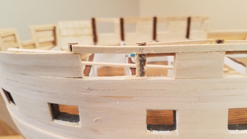
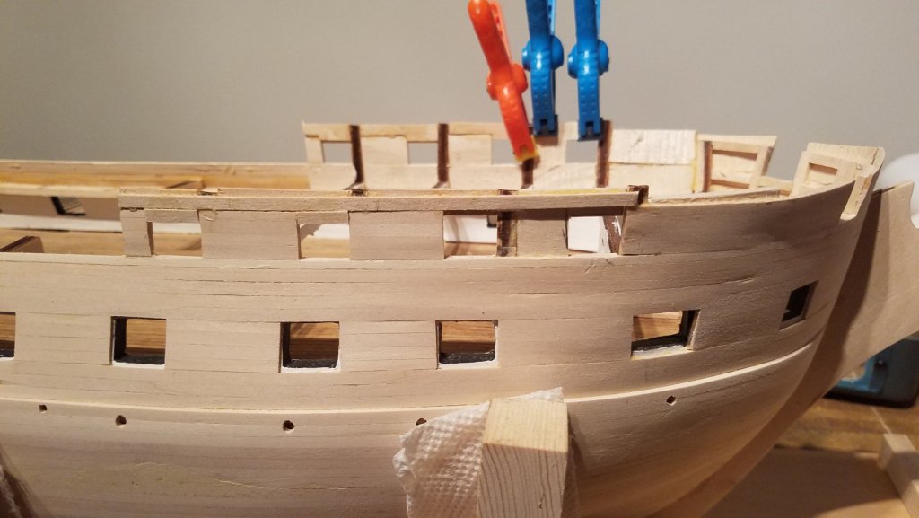
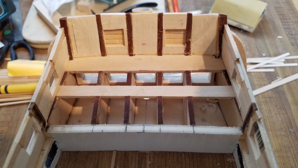
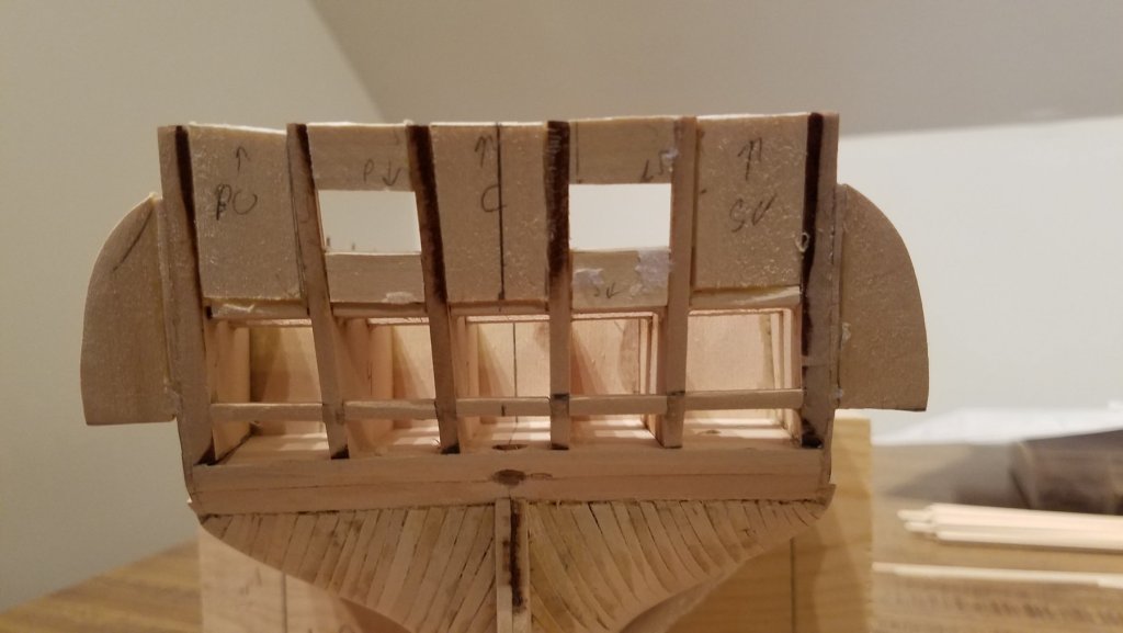
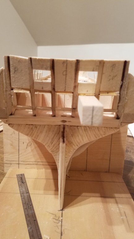
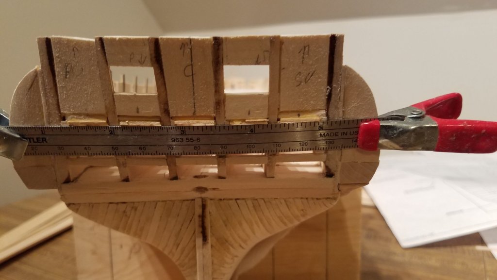
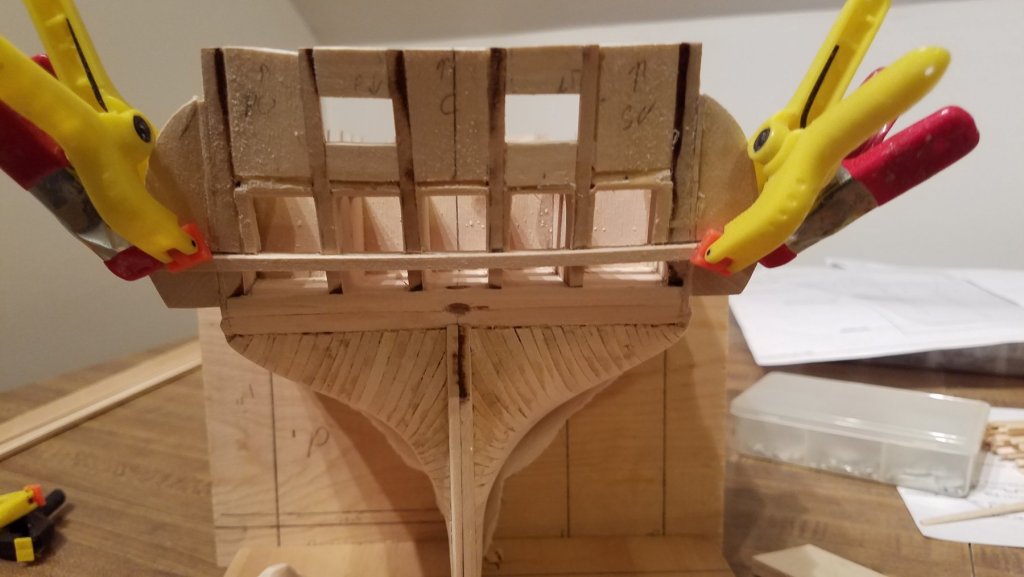
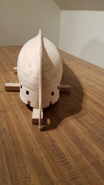
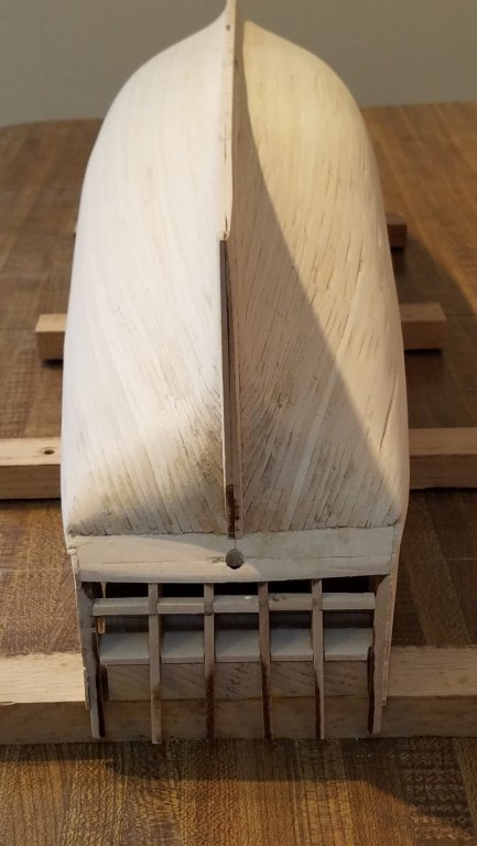
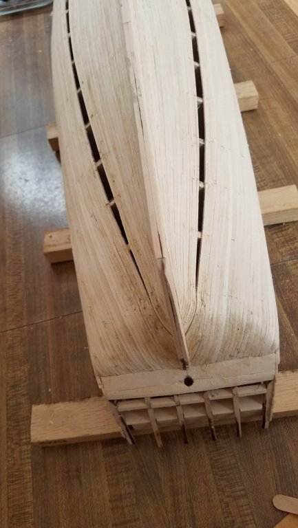
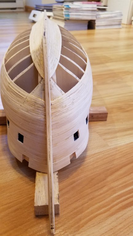
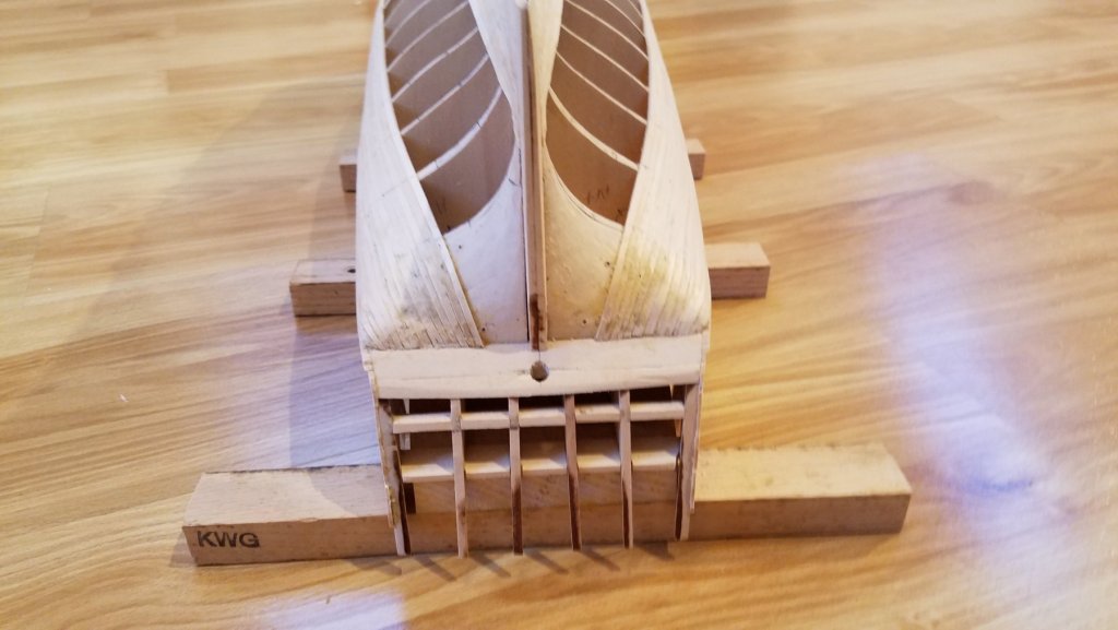
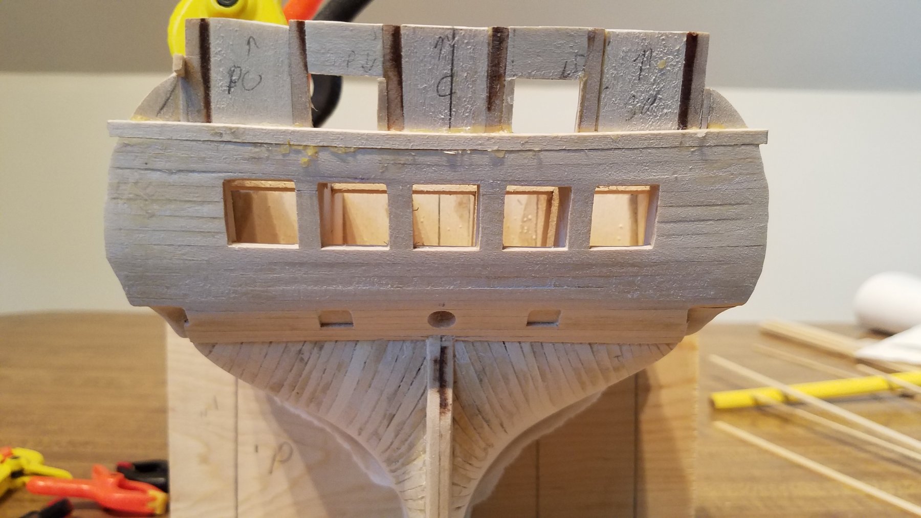
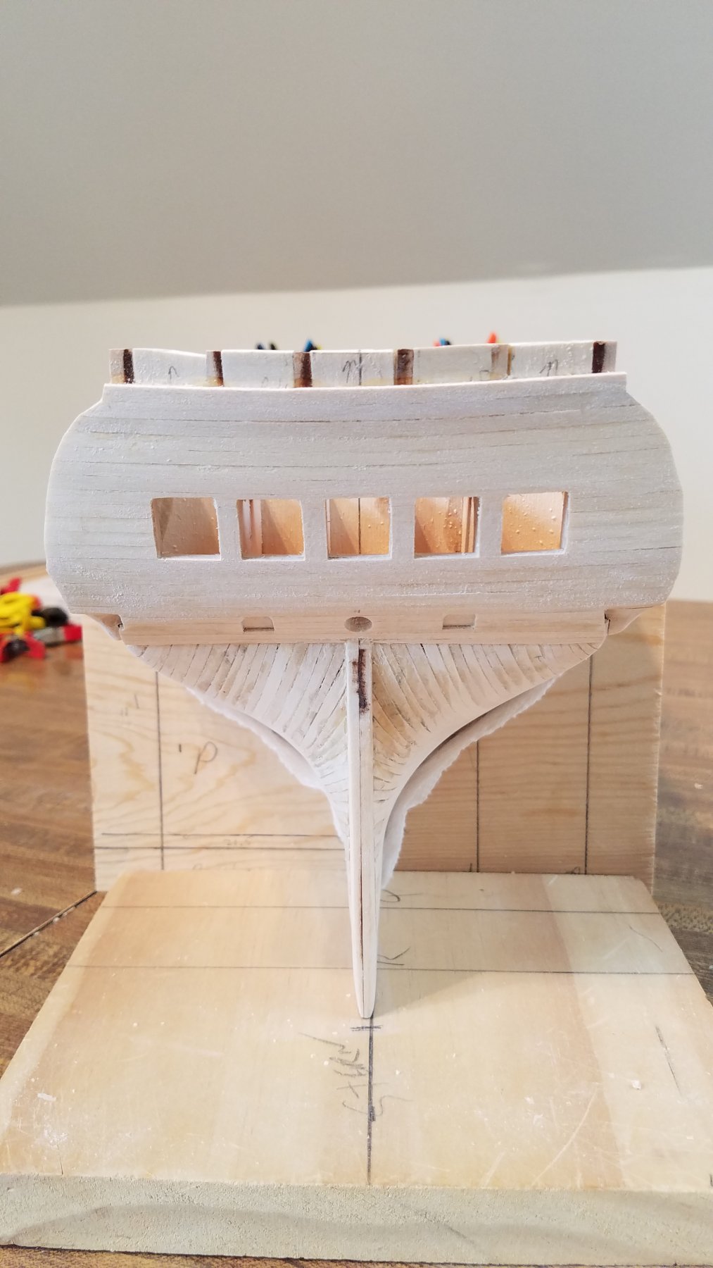
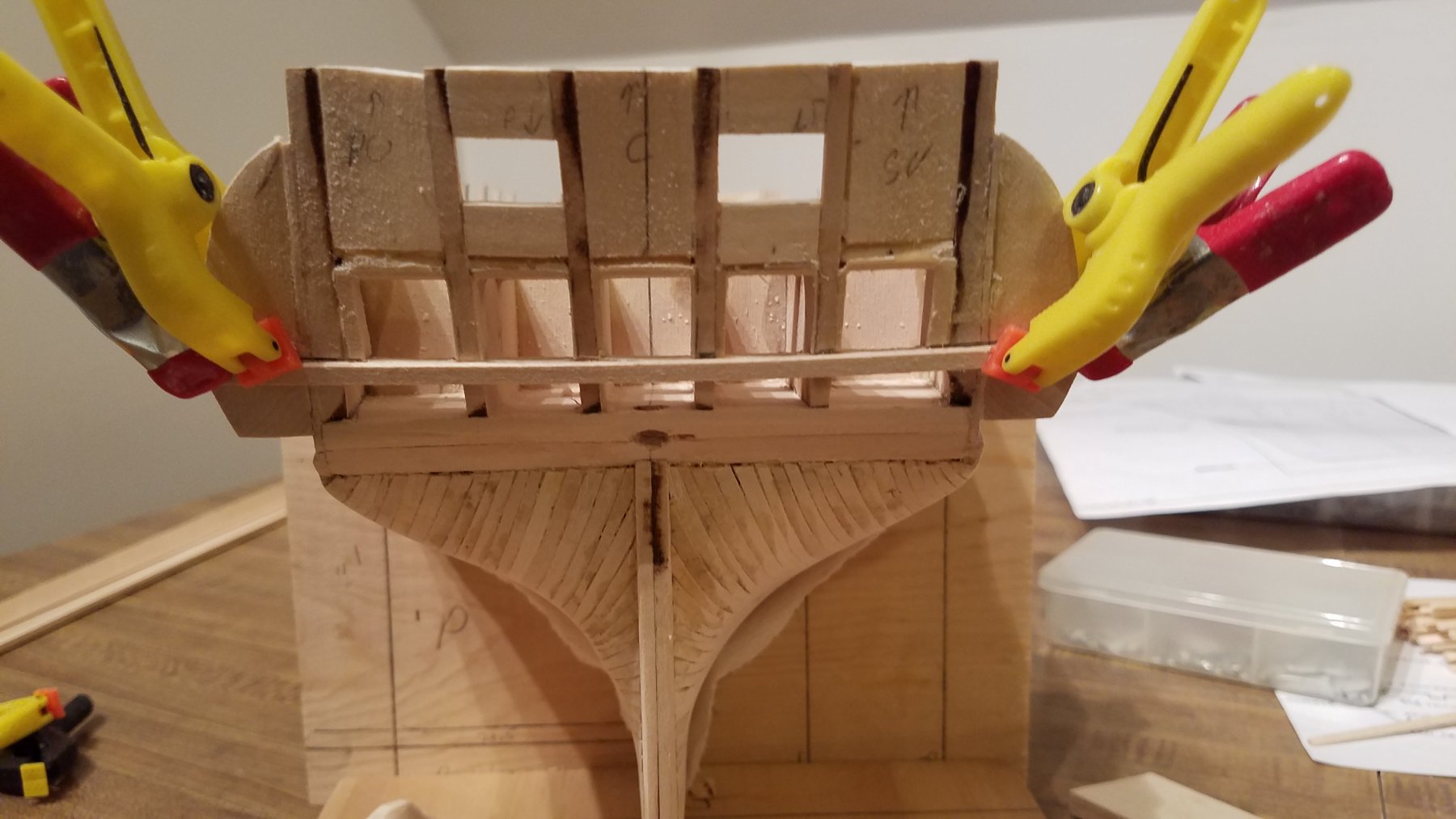
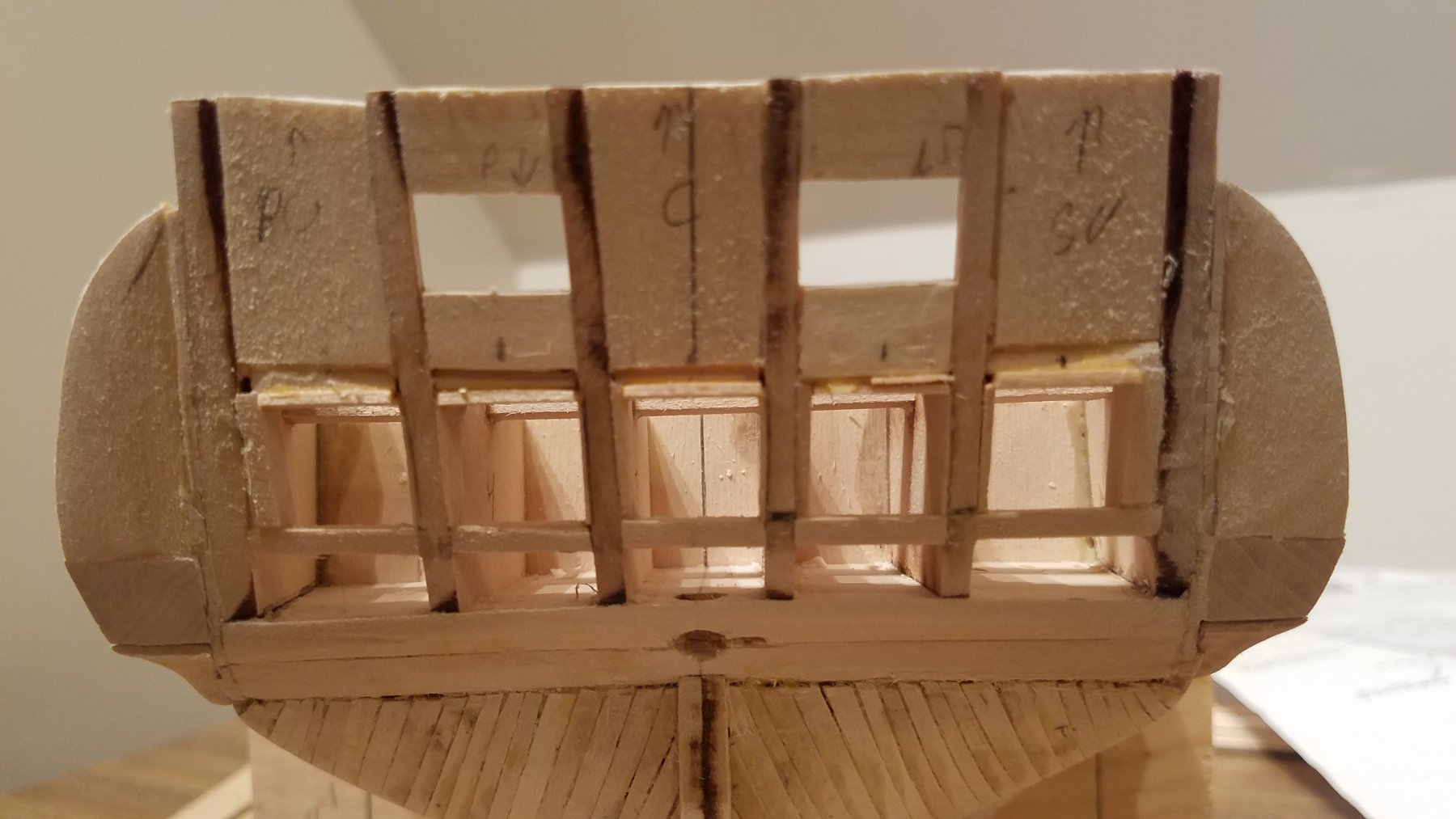
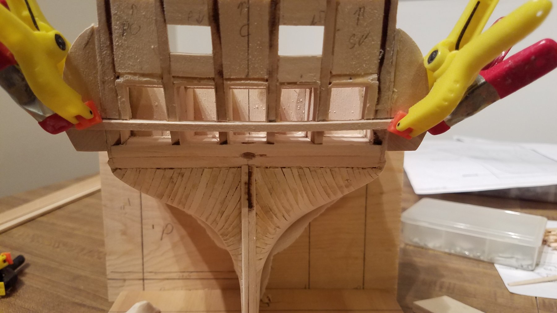
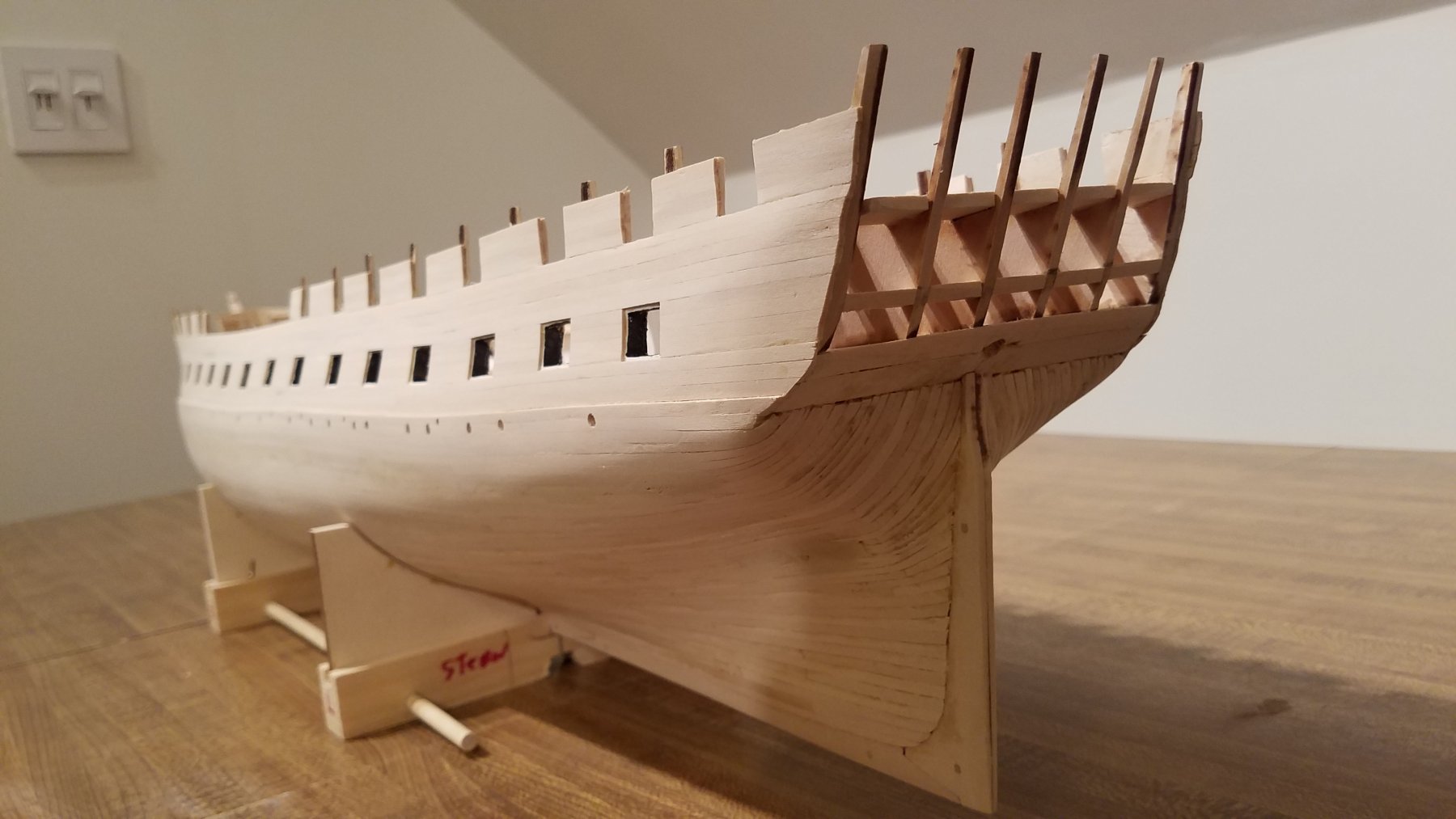
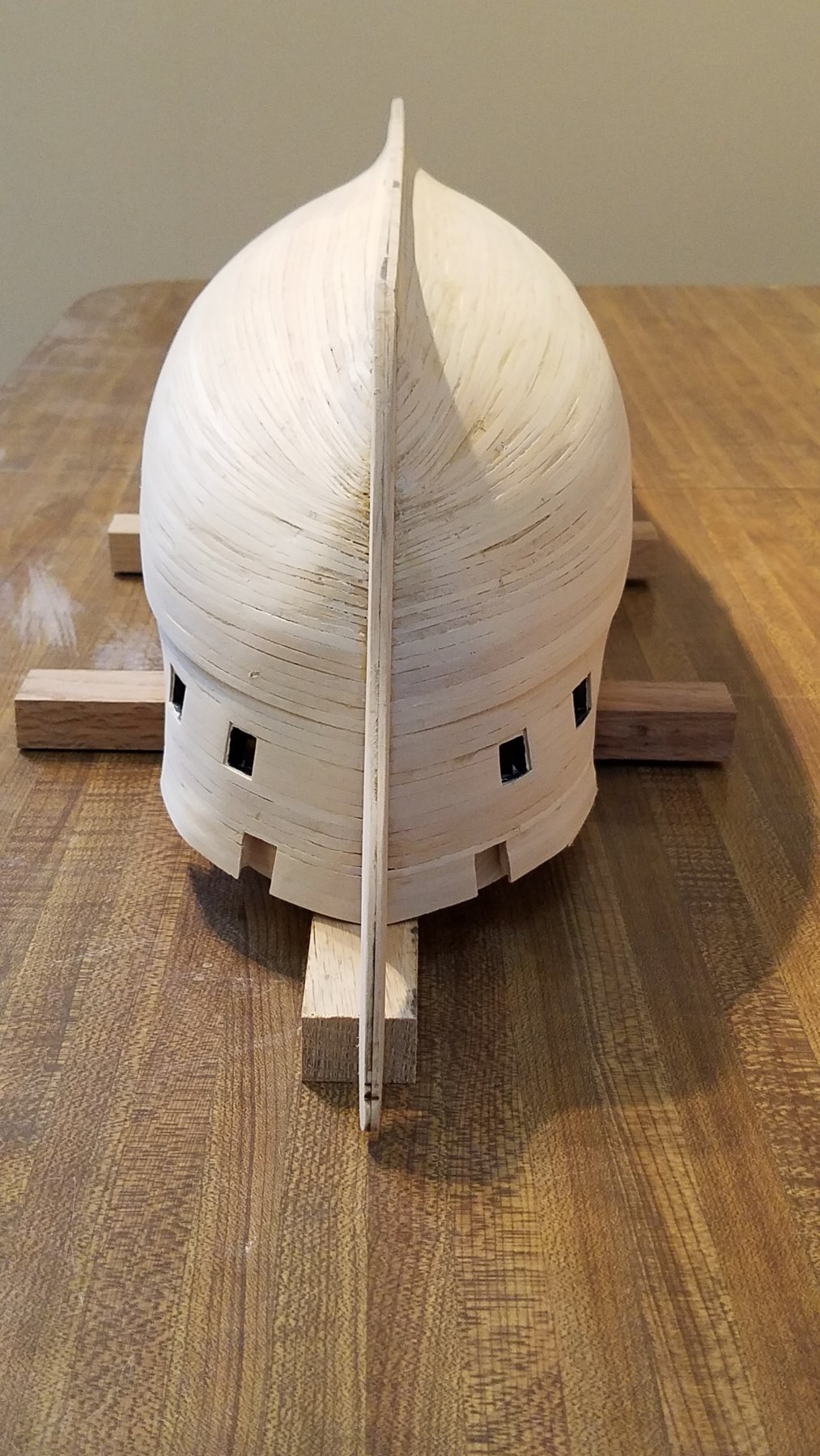
So time for my next update. The stern... Well after being thoroughly pleased with myself for how the hull planking came out..... I though finishing planking the stern would be quick and easy... boy was I WRONG. (again) First pic.. The old Gal back in her build cradle. Now for the stern First I glued on the ears. Even as I was doing that , I knew sooner or later I would wind up breaking off the tops of the stern "risers"?? tops of the stern bulkheads. They are really thin, fragile and not supported by anything. Since I needed to frame in the stern gun ports on the Spar deck anyways... I used the same technique as the other gun-ports.. Basically made them solid! Note the filler pieces are not rectangular. That would be to easy. The spar deck port openings are just roughed in at this point. Latter on I'll clean them up to proper size . Right now they are there to prevent me from breaking off the stern timbers. Before I can go much further, I knew I had to position the quarter galleries. So I cut out and shaped two lower solid pieces. This was done similar to how the bow and stern spaces were made. Square block... mini table saw to right size, Then scroll saw to get close to the right shape. Then table sander to finish up. Then I started the decorative fitting that goes underneath. For the lower pieces, I dove into hand carving with a number #7 exacto blade Notice the lip on the upper right piece. That fits over the wale . The lower pieces will sit on the wale. and then the upper pieces will sit on those. So If I measured right.. They will all align and be at same height and symmetrical relative to the wale Like So... Note at this point, the upper blocks are glued on. The lower blocks are just dry fitted. They lowers do need more fitting and sanding to be flush with the upper pieces. Those lower pieces were my first ever free hand carving. 🙂 Next, Need to frame the 5 stern windows. Like the gun-ports, I made a jig. basically a piece of wood 14x14 mm. That's the size of the stern window frames. The challenging part is that 1. The stern angles outwards (further to stern) as it goes up to the top rail 2. That the stern framing is NOT straight up and down. They cant outward port and starboard 3. The stern framing are not exactly parallel to one another. They are at slight different angles. So with those three challenges... Need to frame 5 perfectly square 14 x14 mm ports , that are aligned and spaced properly. Ugg I know it looks rough, but you can see all the shims of various sizes in place. pretty much all 5 windows needed shims on 3 sided. The bottom sill was correct and my starting reference point. You can see the tick marks above each window. My methodology was I basically measured and marked the center-line of the stern. Then measured from there and marked where the center of each window should be. My Jig also has the center-line marked. So I aligned the center-line of the jig with the center-line mark for each window. Then positioned the shims around the jig. Easy ... NOT! Now.. Finally, I glue on the first plank. First one is aligned with lower window sills. So much for stern planking being quick and easy!! 🙂 And that's where I'll leave it for today. Hopefully next update will have most of the stern planking finished.


-
Well I must concede. Captain Steve is an honest man. For he said there be more redness to come for a royal barge it be. At truest he was.. for not only more a redness hue there be, but the Capt Steves barge is looking most regal indeed! And while the barge may not have the contrast of blackish and whitish the old gal Connie will someday haveth... The redish hue does grow on one and the bardge be most hansometh Congrats to Capt Steve!
- 48 replies
-
- 5
-

-
- queen anne barge
- Syren Ship Model Company
- (and 1 more)
-
Congrats Used2Sail You made a true work of art. And a fittimg case to show her off. Thanks for the your build log. Its both a source of inspiration and my go to log as I reach each new step in my own build. Congrats again. Looking forward to following your next built. K
- 1,350 replies
-
- 4
-
-
- constitution
- model shipways
- (and 1 more)
-
Src Excell to build model wooden boats. Whoda thunk. But thats what you get when you put an IT guy in a woodshop. Grin Excell is helpful. But visio is actualy great. Scan in the model blueprints. Then you can scale to 1:1. And draw out and then print components to scale. Poor mans cad.
-
Capt Steve. Ur hero's planking and nailing tis looking mighty fine. But i,'s got to say that red is looking mighty err well Red 🙂
- 48 replies
-
- 4
-
-
- queen anne barge
- Syren Ship Model Company
- (and 1 more)
-
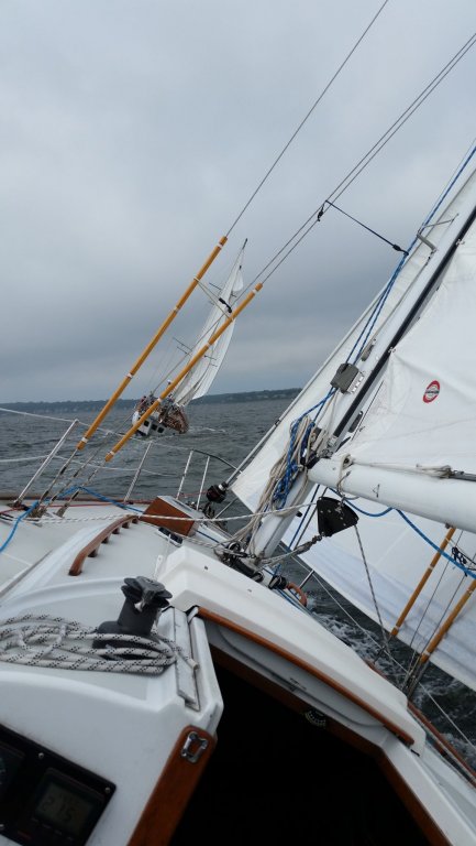
Jon, Jon, Cpt Steve, Used2Sail.... Thanks all for the kind works / Encouragement /Likes. Currently I'm working on framing out the stern window openings and and making the quarter galley lower pieces right now. I'll post some more pics this weekend. With us heading into Spring and warmer weather here in the New England... My time spent and motivation on Connie will go down to a trickle as I switch gears from model boats to preping and maintaining and then sailing the real sailboat.. Here is what I Imagine I'll be doing soon!!! HMS Surprise (Ex HMS Rose) Which I actually did get to sail on once for 2 weeks as crew (it was amazing!) Here is what I will eventually be doing this summer I'm at the helm taking the picture. Would have been better if I was taking a picture over the stern of him chasing me with a stern chaser run out (grin) And here what real boating is about. And what I'm actually doing ..LoL Sanding , scraping, painting, fixing. Then more scraping, more sanding, more painting and more fixing. K


-
Tom Looking case is looking awesome and Massive!!! couple of questions -How did you secure the pexi in the panels. I see you have a channel.. bu I did you use some sort of adhesive to keep in place? -How will you get the model in the case when she is done. I'm guessing one panel will be hinged or removable? K
- 1,350 replies
-
- 1
-
-
- constitution
- model shipways
- (and 1 more)
-
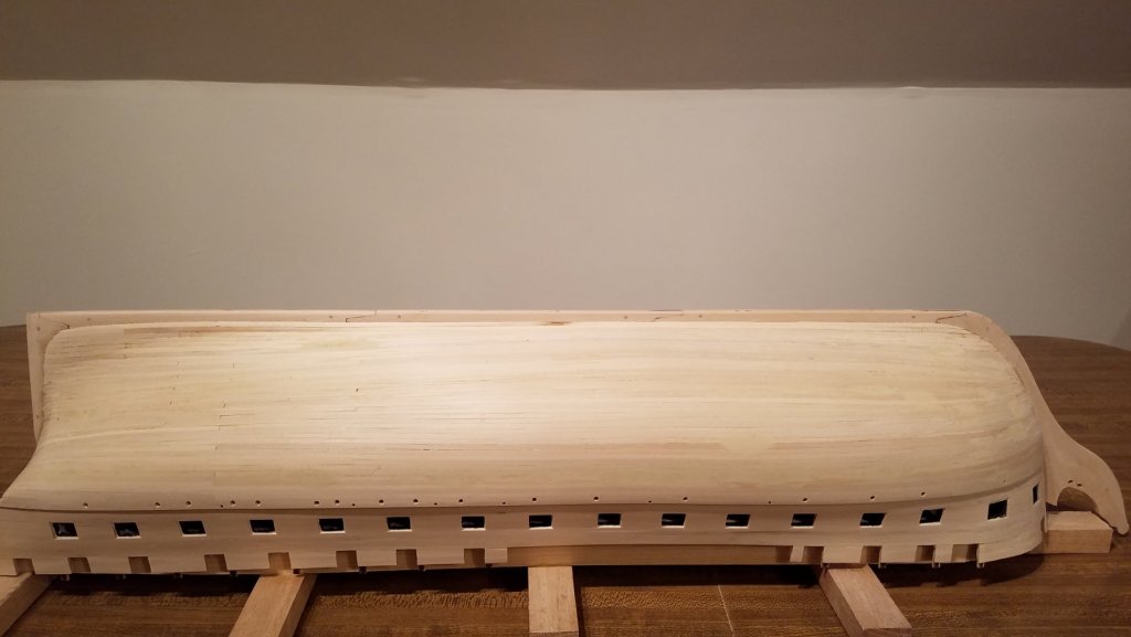
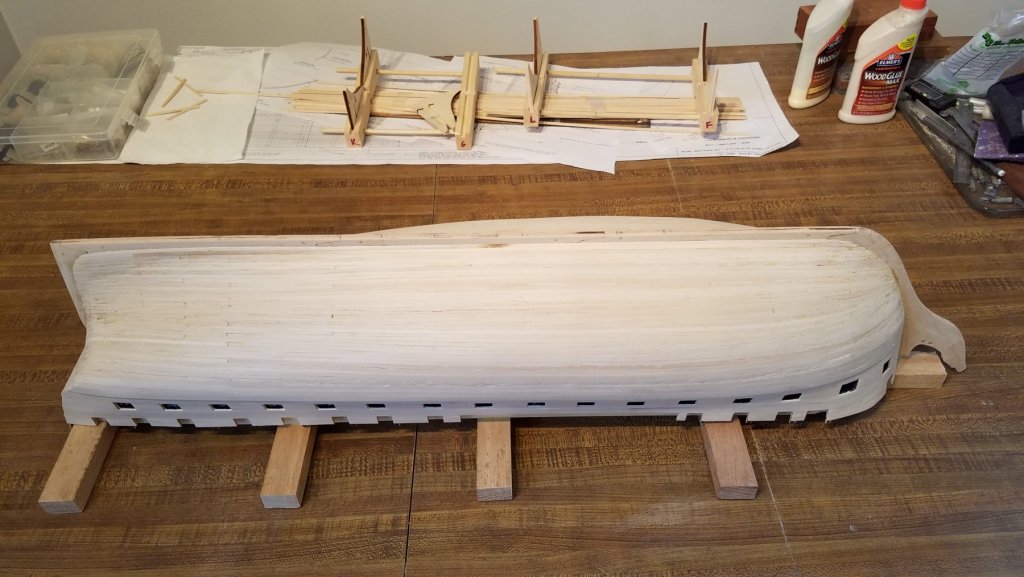
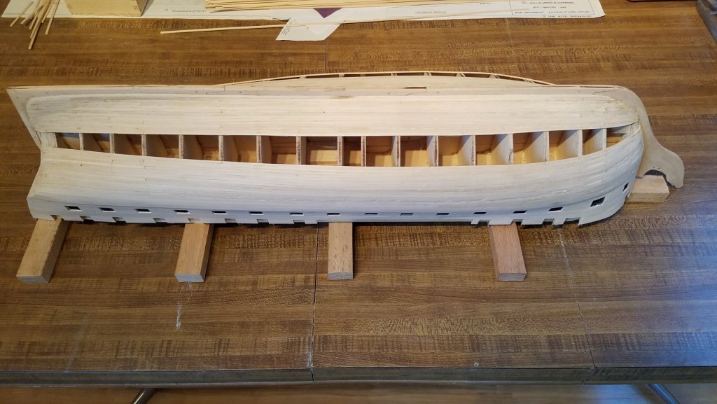
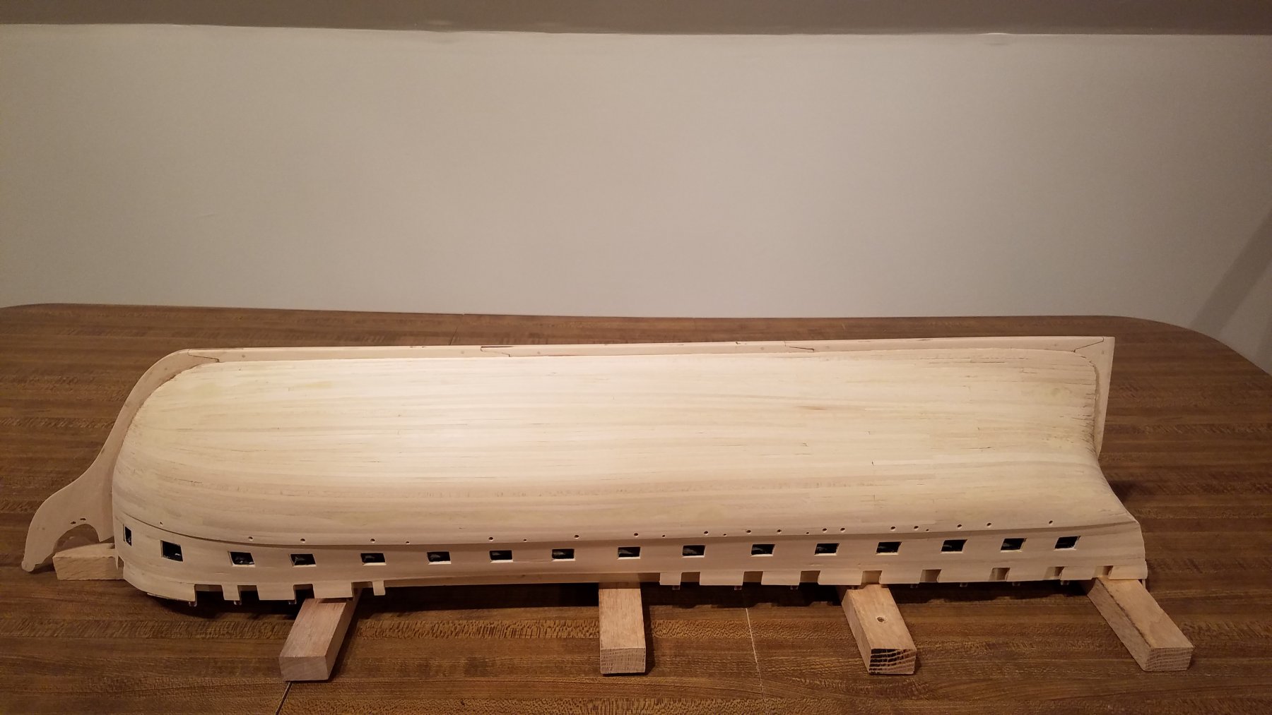
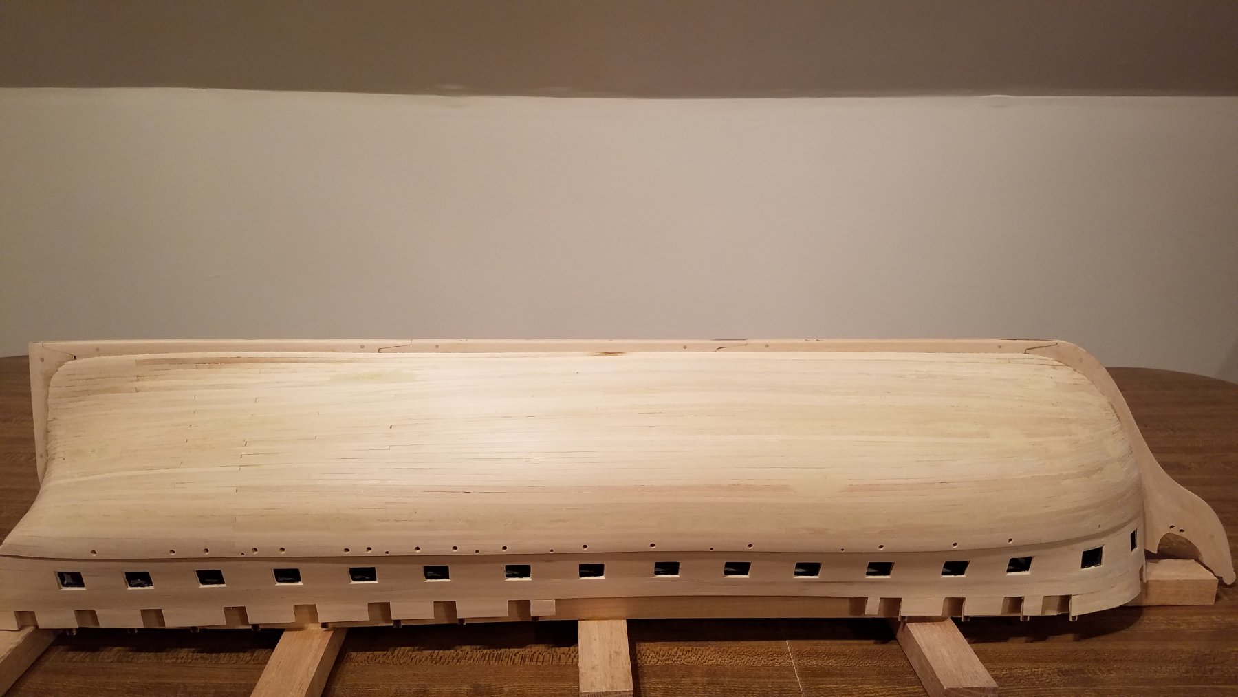
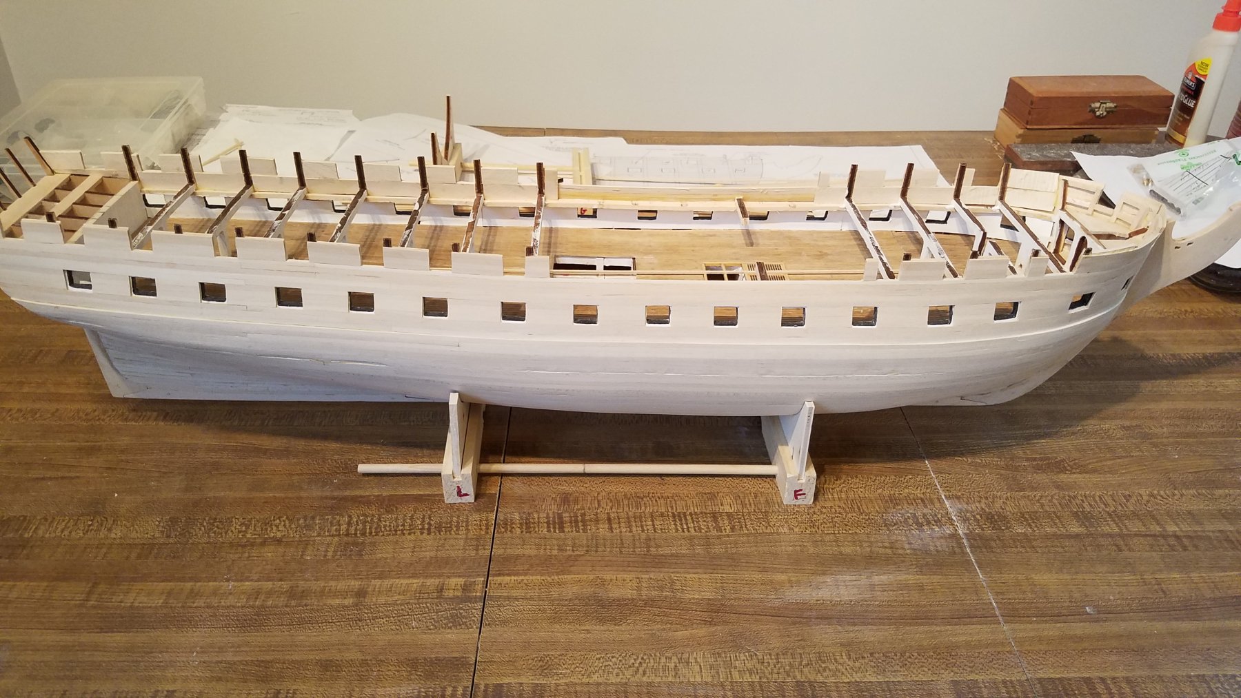
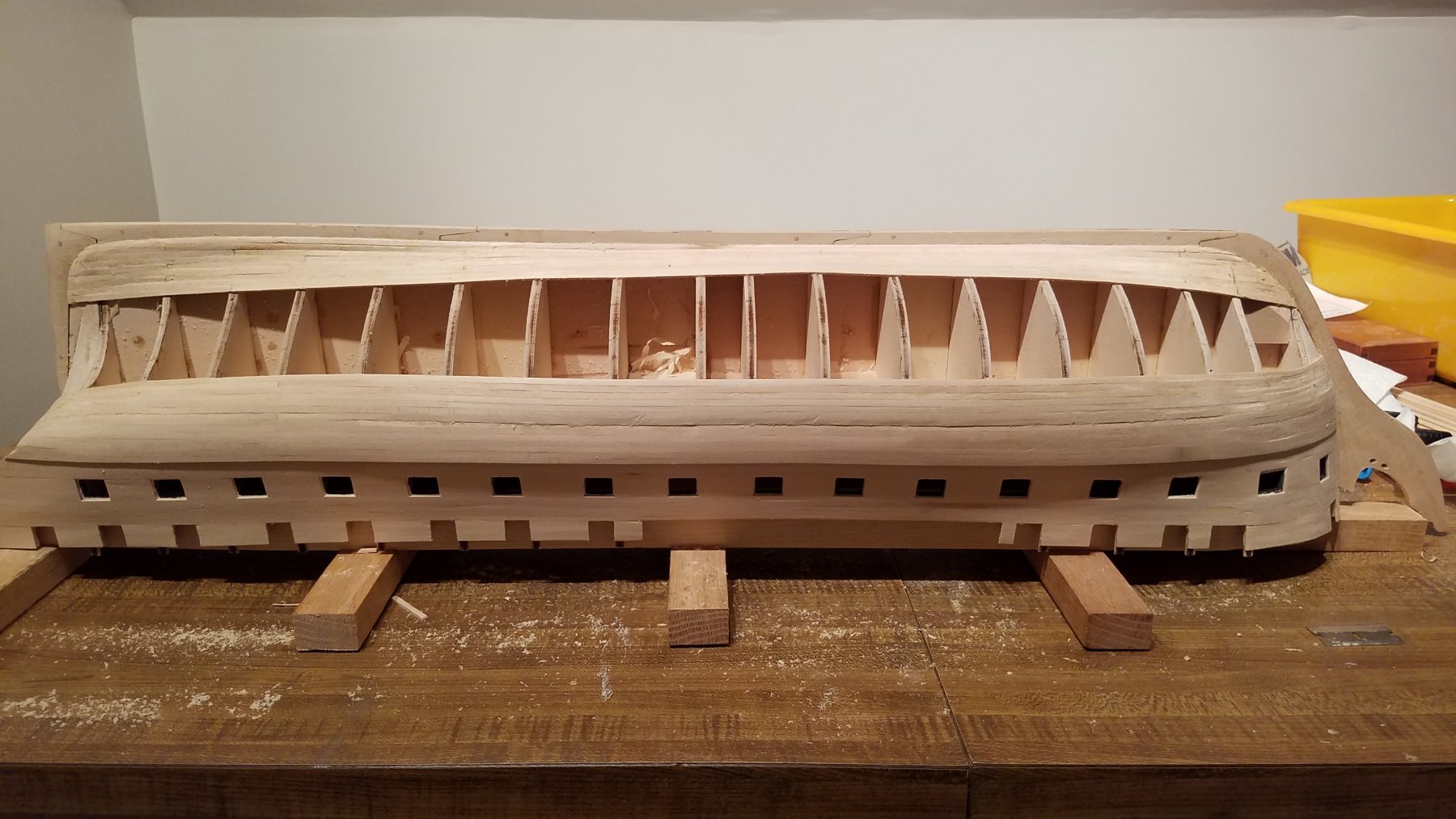
Part #2 Cleaning up the hull. So again.. I didn't take any pictures during. not much to see. Just pics when process was done. Basically I sanded the hull down with 220 grit sandpaper. After sanding.. I vacuumed the hull to pick up all the sawdust Then I used plastic wood wood filler to fill in all the dings, nicks, and low spots etc. I was quite generous with the filler. i.e filled in so it was proud on the hull. After the wood filler dried... sanded it back down to smooth again with 220. It actually sands quiet well and easier/softer than the wood. So I was able to sand off the excess filler without thinning the wood further. Next I repeated the filler/sand process 3 more times. Each time the areas that needed filler were fewer and smaller. After the last time when I was happy with the hull, I did a final sanding with 320 grit sandpaper. Vacuumed again And the result is.... Next up... I'll clean and install the mettle port-lights and scuppers fittings in holes that are already drilled out. Then I'll be plank the stern. Just frame the windows.. No stern decorations yet. At that point I'll be ready to prime the hull. Still have some work to do before I'm there, but i'm getting eager to see her with the black hull and white gun-port stripes... That's it until next time.


-
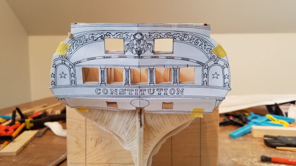
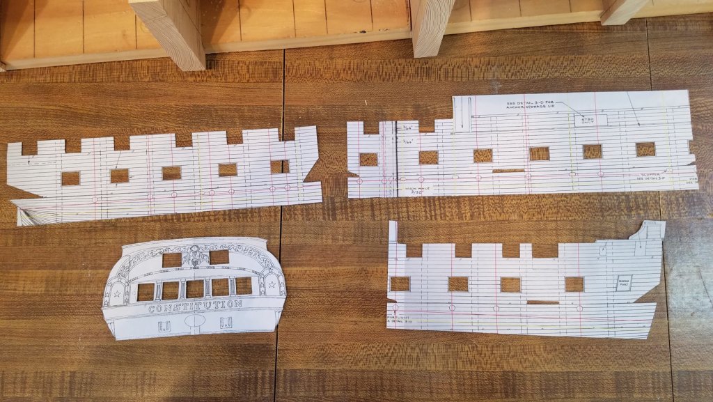
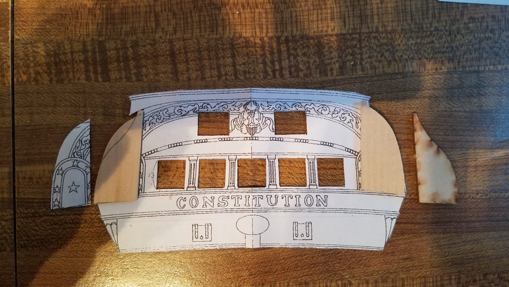
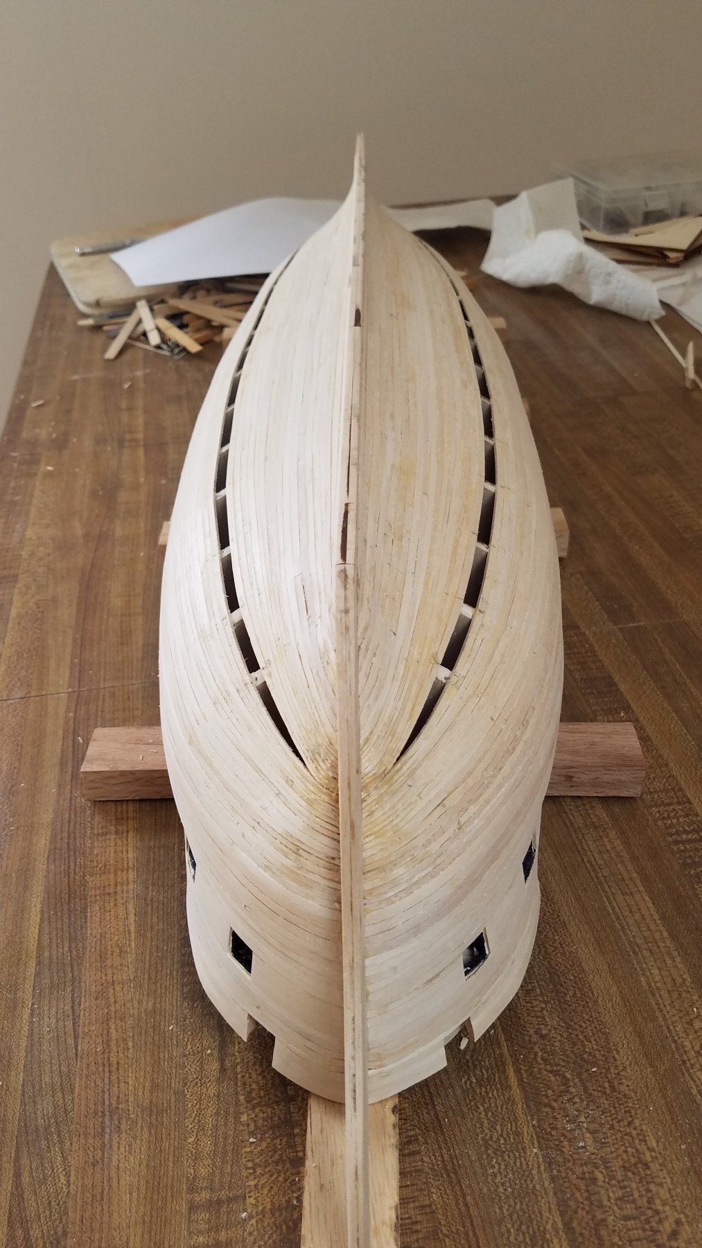
Alright.. time for my next update First.. I made a few templates I printed to scale... the 5 window stern from AOS The side view of the hull from the kit plans. Cut this into 3 pieces Cut them out For the stern... I still need to ad the ear pieces to the side of the hull that are the back of the quarter galleys The laser cut pieces that came with the ship are a good match for the present stern. but is smaller/ less rounded than the 1812 5 window version So using the template and some scrap from the kit... I made new ones that are the proper shape. So those are ready to glue on now. I'm holding off working on the stern and adding the ears to the hull until hull is all sanded. Otherwise they will be in the way of sanding and sure to be broken off. The other template.. side of the hull... I used to locate the position of the scuppers and port lights on the side of the hull near the top of the wale. Sorry I didn't take any pics using the template.. but here is the result after marking and drilling the holes. The lower, but larger holes are all set to receive the port lights. The upper holes I need to enlarge, and make more oval to fit the scuppers. Used same template for both sides. but needed to look at the back side of the template when working o Port side. No big deal.. As I did starboard first. holes were already in the template. note when using the template....line up the closest gun-port. then mark the holes. As the blueprints are 2D and the hull is 3D. They dont line up along the whole length of the ship. That's the reason for cutting into 3 pieces and doing in section. Note in the last picture.. you can see the hull needs quite a bit of cleanup. A good number of gouges and uneven planking. Especially around the transition from the bottom of the wale to the lower hull. Will need lots of filler and sanding
-
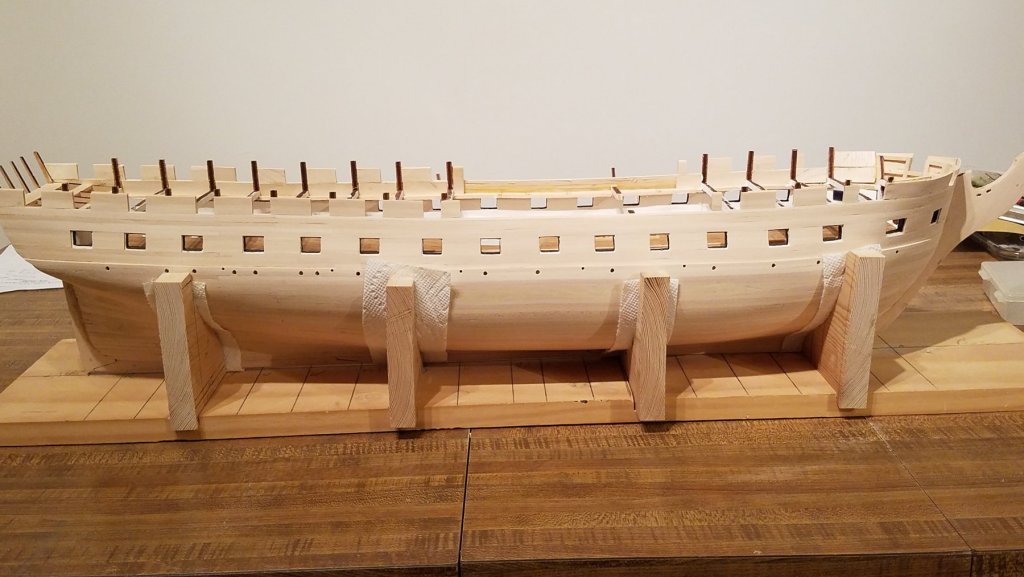
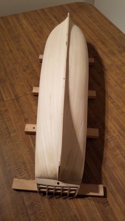
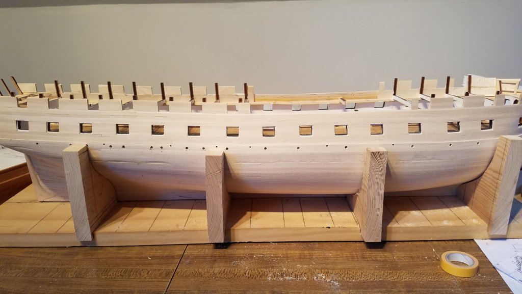
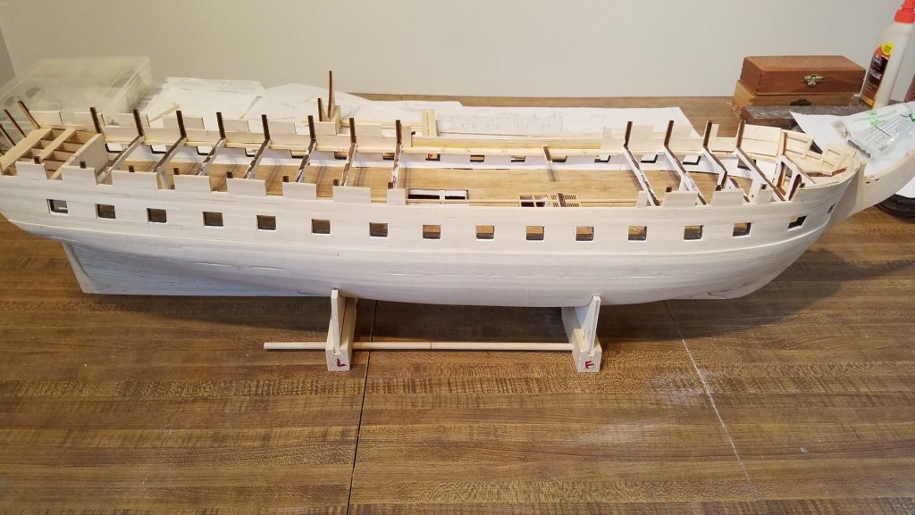
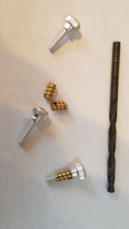
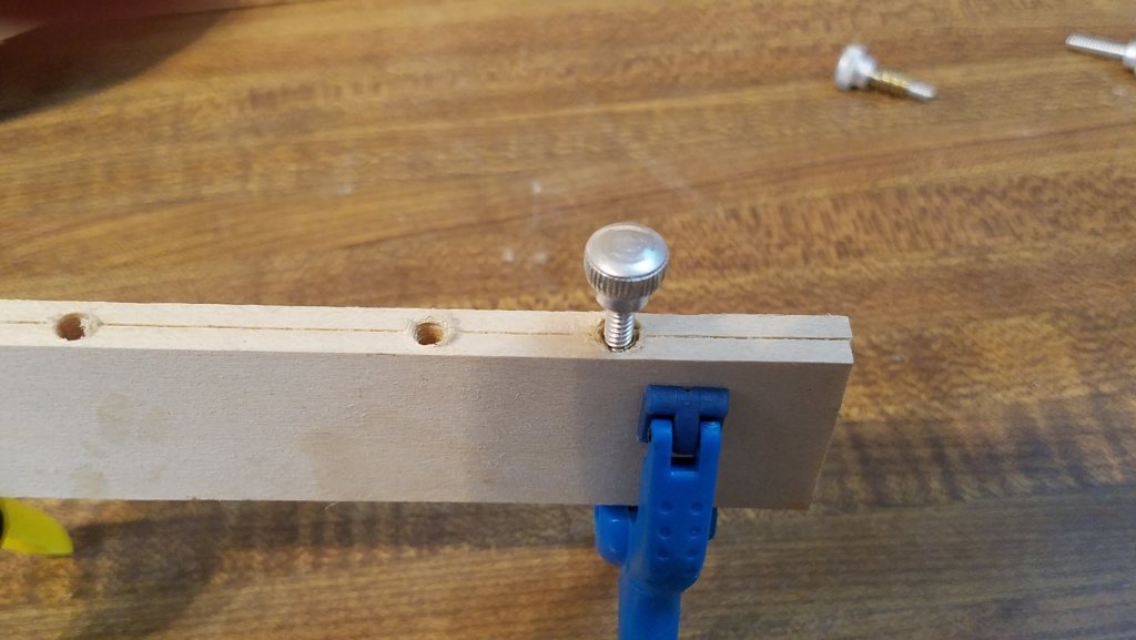
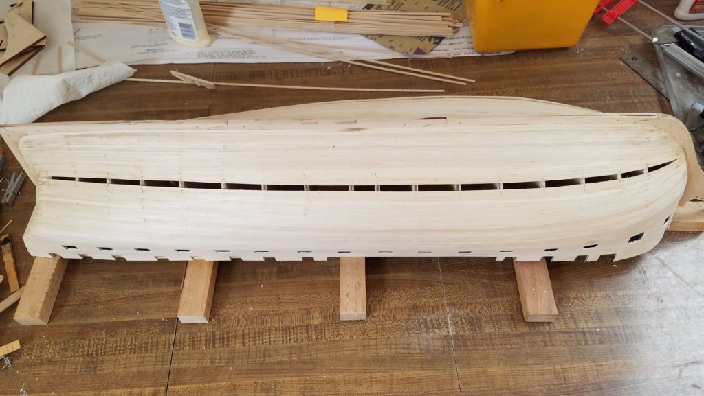
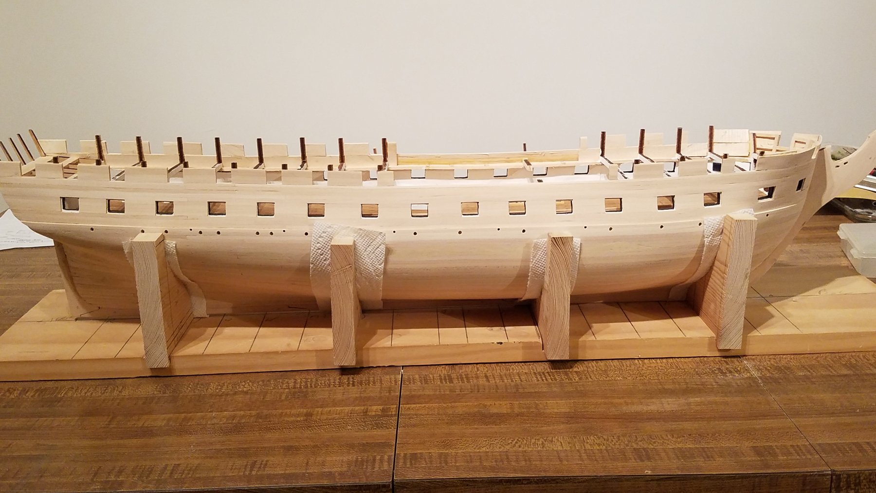
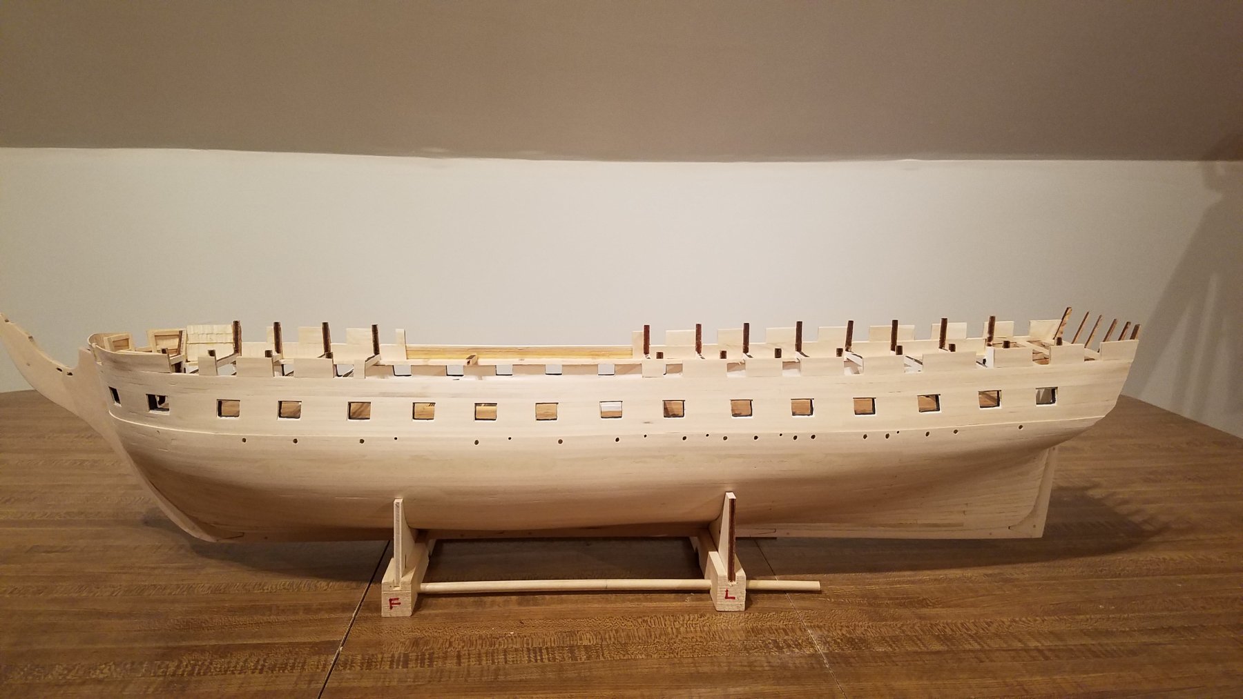
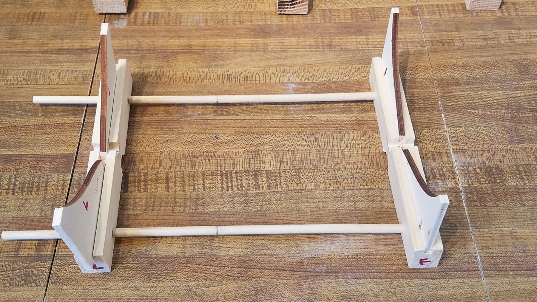
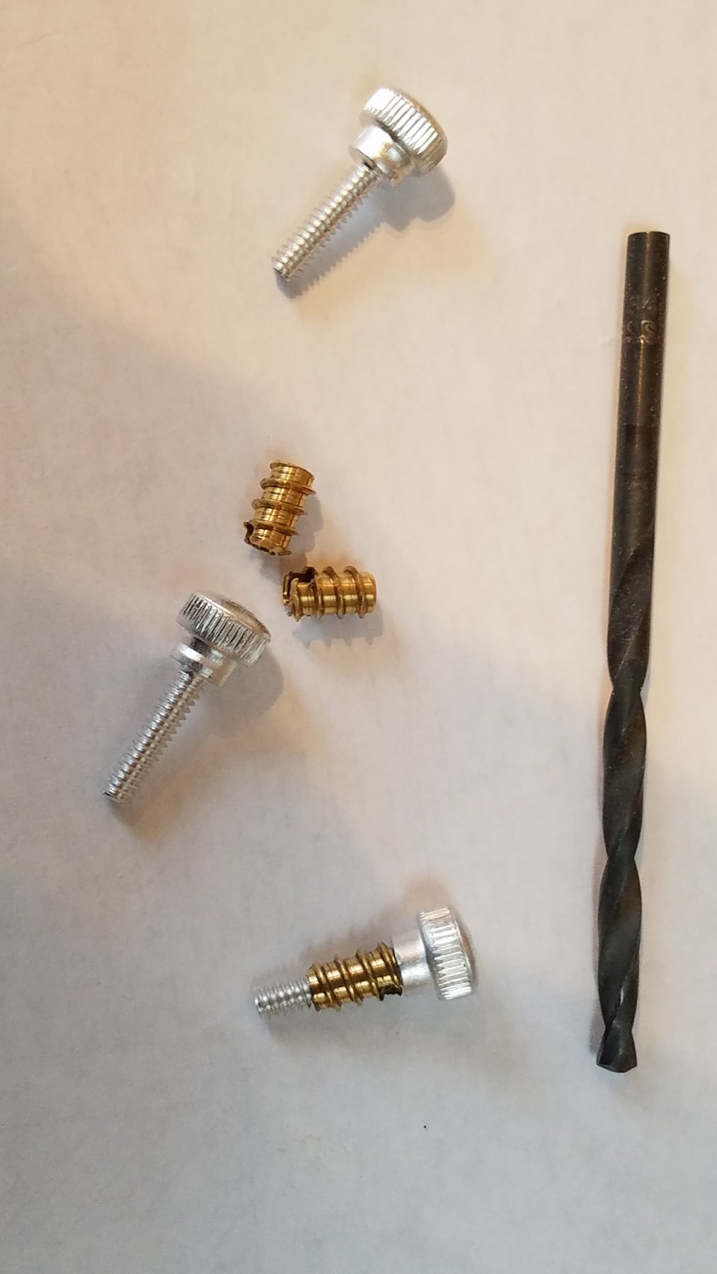
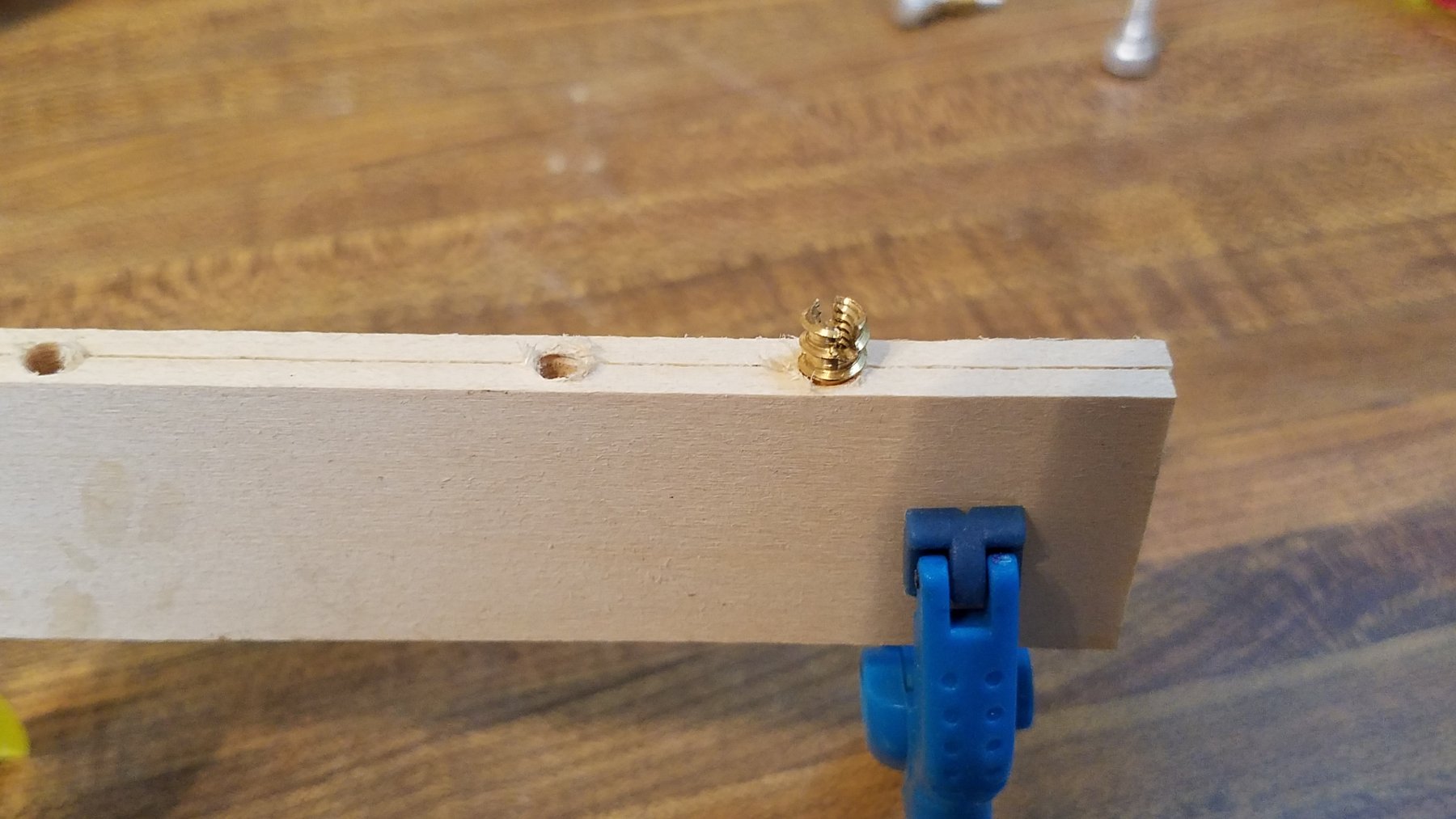
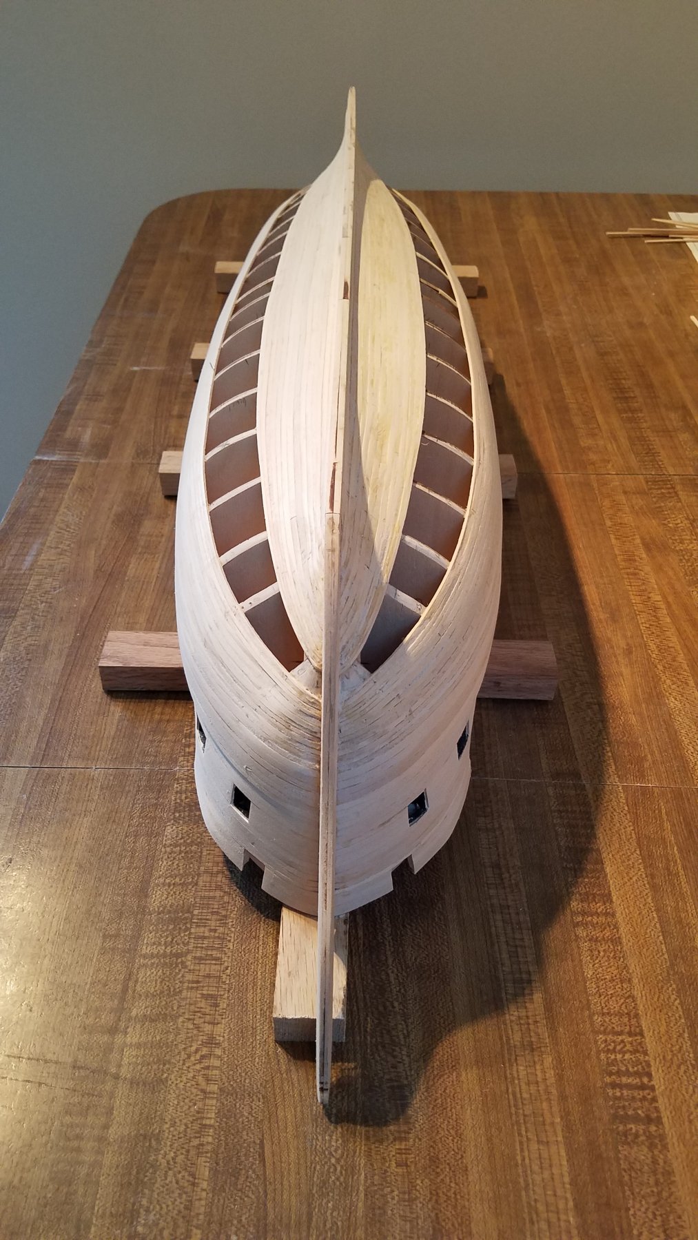
Planking done.... not counting the stern. Still needs quite a bit of sanding and cleanup. Really only 1 plank (each side) that didn't run from Bow to stern. And not a single stealer. Will need a bit of wood filler to fill in a few spots Overall... I'm really happy how she came out. also made a prototype stand. just to get the shape/position right.. And I found these threaded sleeves. and thumb screws made a test piece..same width as the keel Now I can drill 2 holes in bottom of keel. Thumb screw will go through the stand into the sleeve in the hull. And I'll have a secure but easily removable way to secure the stand. (when I get to that point in say 3 or 4 years . HeHe


-
Thanks Tom. Soo close to finishing planking.

-
Great Reference photos. Thanks Guys! I didn't realize they took off the top gallant caprails on the last refit.. Now If they would just put her stern windows and quarter galleys back to one of the 1812ish various version... 🙂 FYI, USS Constitution Model Shipwright Guild currently having their annual Model show at the Museum through March. I Highly recommend to the show if your in Boston. Some really exceptional models .... and craftsmen. I'm going to go see the show and this ship again either next weekend or weekend after... depending on work and weather. In New England.. we expecting snow storm tonight. The good news is I can stay in tomorrow and do more modeling!!! (after shoveling) Now for My update. I finished my next set of planking bands. There were 5 planks in each band. So another 10 down per side. I did some basic cleanup of the planking so far. Used a razor blade to scrape off the glue on the surface and the ridges where the plank edges meet.. Then did some initial sanding with 200 grit sandpaper. Finally I re-calculated the remaining space. and the plank widths at each frame At this point, the gaps at each frame (port/Starboard) are either a match or within 1 mm of each other. I'm really happy how its coming out very symmetrical. I am down to 10 more planks per side remaining... then planking will be complete... soo getting close. The remaining gap is definitely getting noticeably smaller... I'm at the point where I will only be able to do 1 plank per side at a time and not two. So it will be a bit slower progress. The Stand At this point.. before I finish up the planking...I need to start thinking about the final stand. I'm going to make some sort of cradle. And I want it to solidly fixed to the hull. I thinking 2 bolts that go through the stand and up into into some sort of threaded sleeve in bottom of the keel. If I can find such a sleeve, I can drill a hole in the bottom of the keel now and glue it in. Also, each of the 2 pieces of the cradle will need to be a form fit to the hull ... and align on a frames/bulkhead. Sooo... need to make it now, while hull is upside down and before I finish the planking.. I'll finish the model in its working cradle ( pics earlier in my log) ( It is much more supportive while working on her then final stand will be) And not attach the final stand until she is done. But that means it needs to be easy to on the finished model. One of the reasons I enjoy this hobby. I have to think about and plan for something that is still several years ahead in the process. HeHe Some Current Pics:
-
Zappto, Looking Great. She is really turning out beautiful. Looks like your close to completing her! K
-
Thanks mtdoramike. Actually, the xls chart didn't really take me that long. The basic sheet I borrowed from Used2Sail. Its all formulas, so after taking the measurements off the ship, the rest just calculates! That said, there's a lot of planks on Connie.. so you must be pretty fast planker 🙂 On to my status. In the middle of planking the hull, so nothing really that interesting to post. One plank, two plank, three plank, four, then repeat.... It seems like forever!! I was able to finish bands A and D. Working from the wale towards the center and then from the gardboard strake to center, Port then Starboard.. Basically sets of 4 planks at time. I've completed 17 planks total per side so far. I then re-measured the remaining gaps again at each frame and re-calculated. Staying accurate so far. port to starboard are within +- 1 mm across all frames I have 21 planks left (per side) to go That's it for now. It will probably be at least another month before I post again. Not much to see, document while I'm planking away. K

.thumb.jpg.04ca062ab6ec5a3d21524c5d47defeeb.jpg)
-
Jon, another.. welcome back. Glad to hear your surgery went well. And glad to see you back to working on Connie. No more surgeries or breaks! 🙂 I'm relying on your log, and progress to keep me moving on mine! 🙂 Best K
-
Vince, I'll repeat my early comments I made . Truly Magnificent!, Inspiring! I love the sails. They look great. Really adds to the model, makes it come alive from a static model to a real ship ready to sail out of port! K.
- 593 replies
-
- 1
-
-
- royal william
- euromodels
- (and 1 more)
-
LowSodiumSailor, Welcome to the Connie Builder Club. 🙂 Search this site. There are a number of us currently building and many more that have have already completed building the Constitution. Sooo lots of great resources, and help available to you. As this sounds like your first wooden kit... and your first tall ship model... you jumped right into the deep end! 🙂 Take your time, ask for help, ask lots of questions, enjoy the build... and you'll end up with a showpiece model at the end. And stick with it. Model ship building is a slooow hobby but worth it. I expect my Connie built to last 5+ years. I think that is typical. YMMV. Connie really is a beautiful ship and makes a beautiful model. Best and good luck! Ken
- 23 replies
-
- 1
-
-
- constitution
- mamoli
- (and 1 more)
.jpg.7b23da6b951a7564eb00c8e43e36f025.jpg)


.jpg.000d47a3a2ac308774c3111fdf717888.jpg)

