HOLIDAY DONATION DRIVE - SUPPORT MSW - DO YOUR PART TO KEEP THIS GREAT FORUM GOING! (89 donations so far out of 49,000 members - C'mon guys!)
×


kmart
-
Posts
195 -
Joined
-
Last visited
Content Type
Profiles
Forums
Gallery
Events
Everything posted by kmart
-
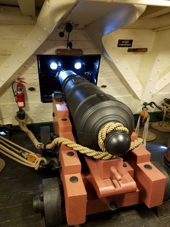
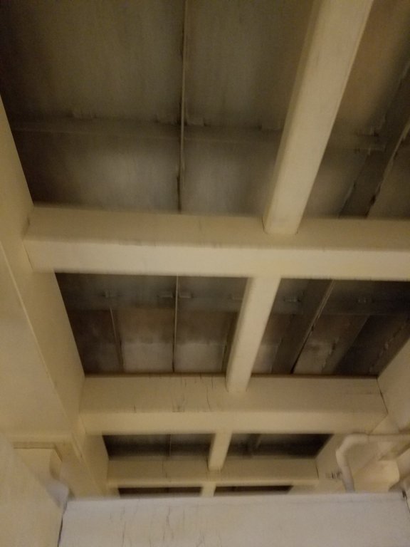
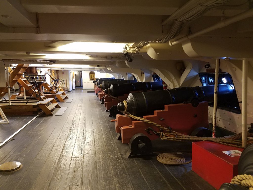
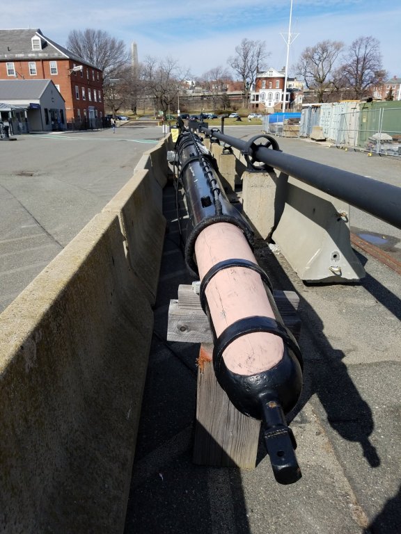
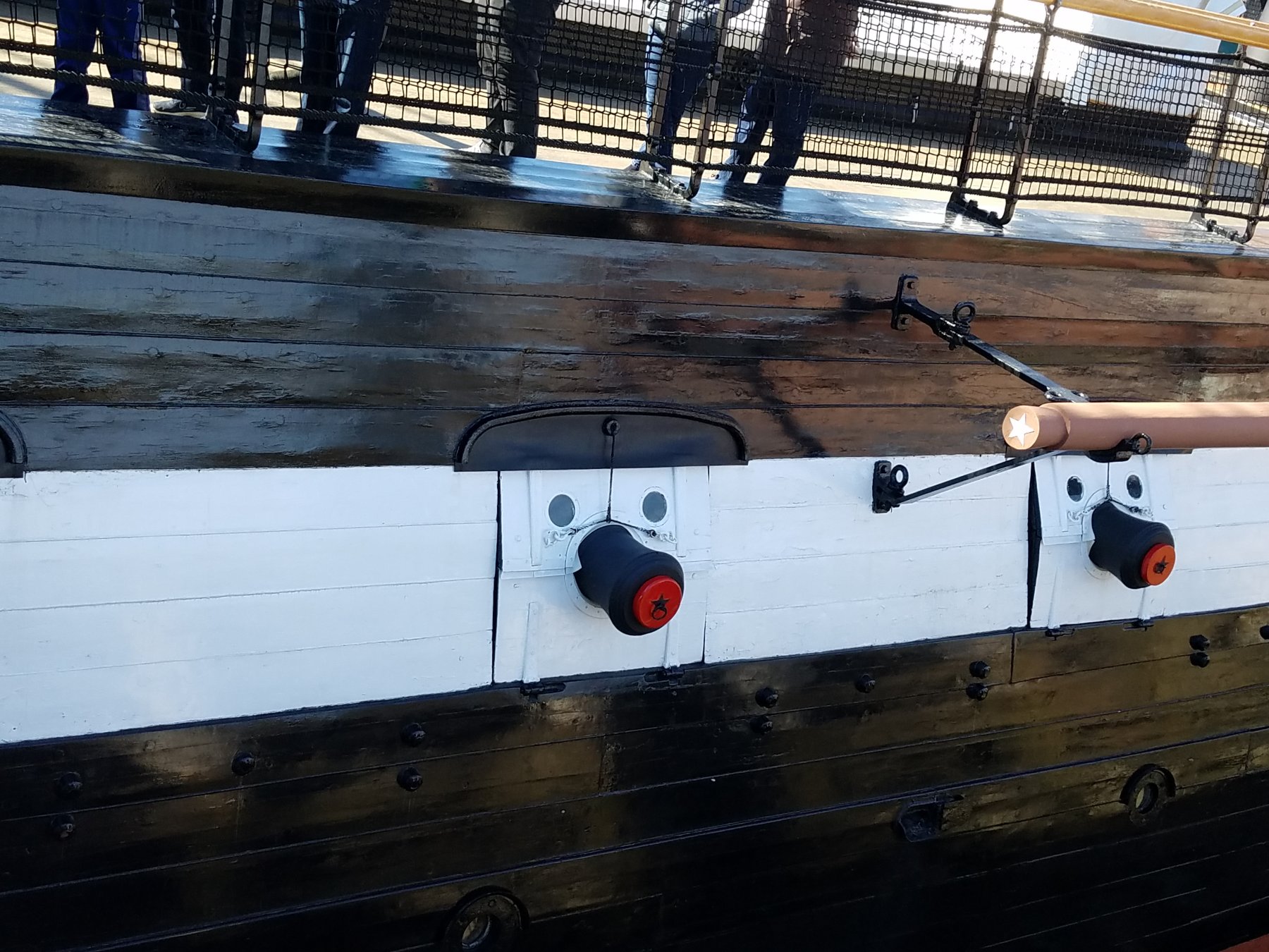
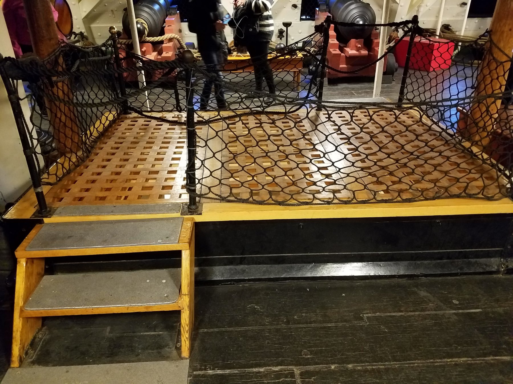
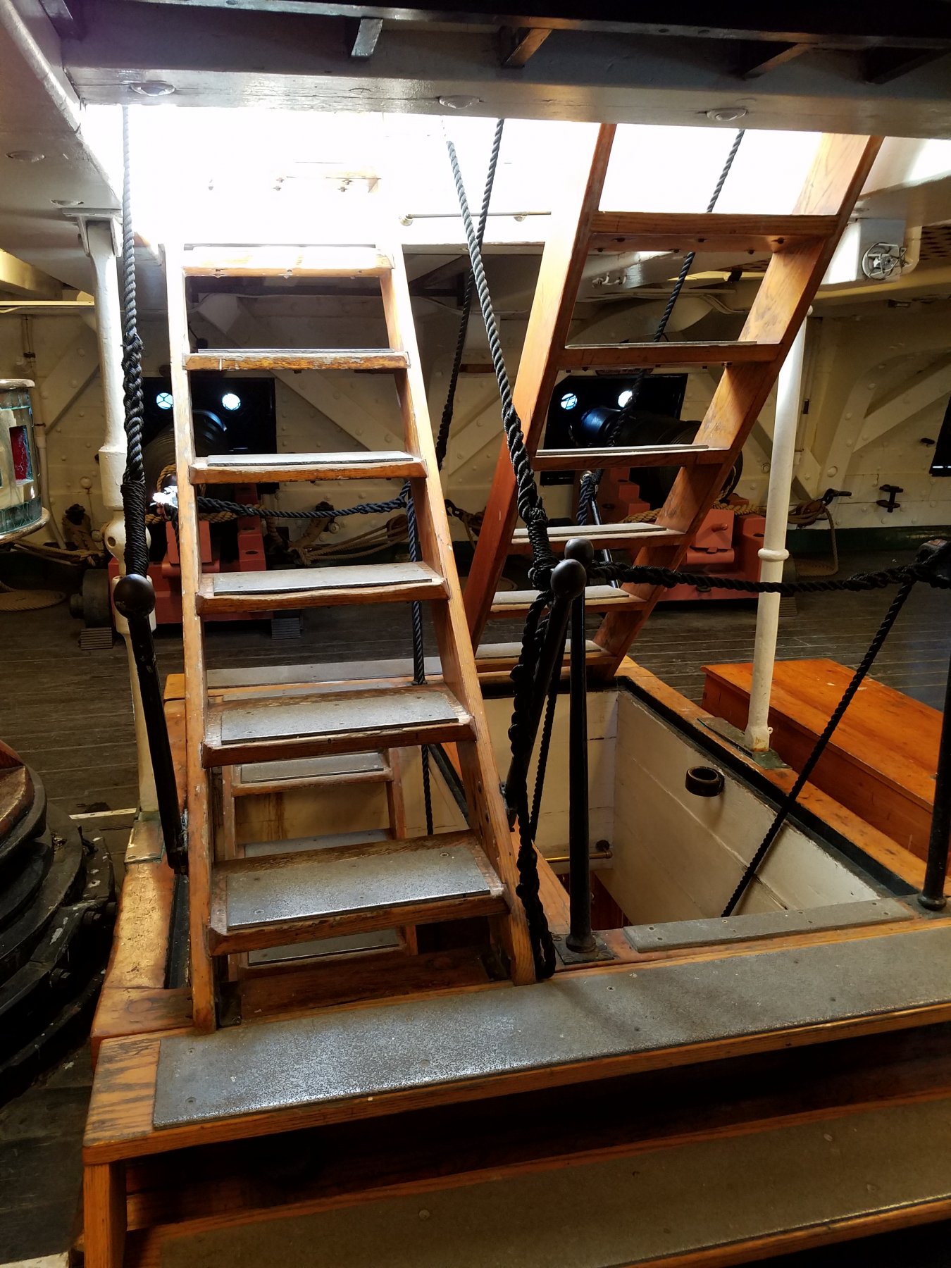
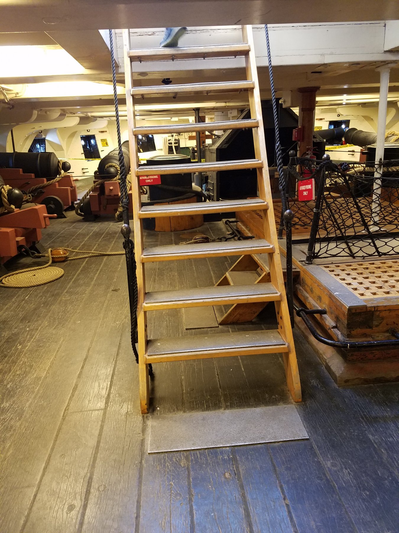
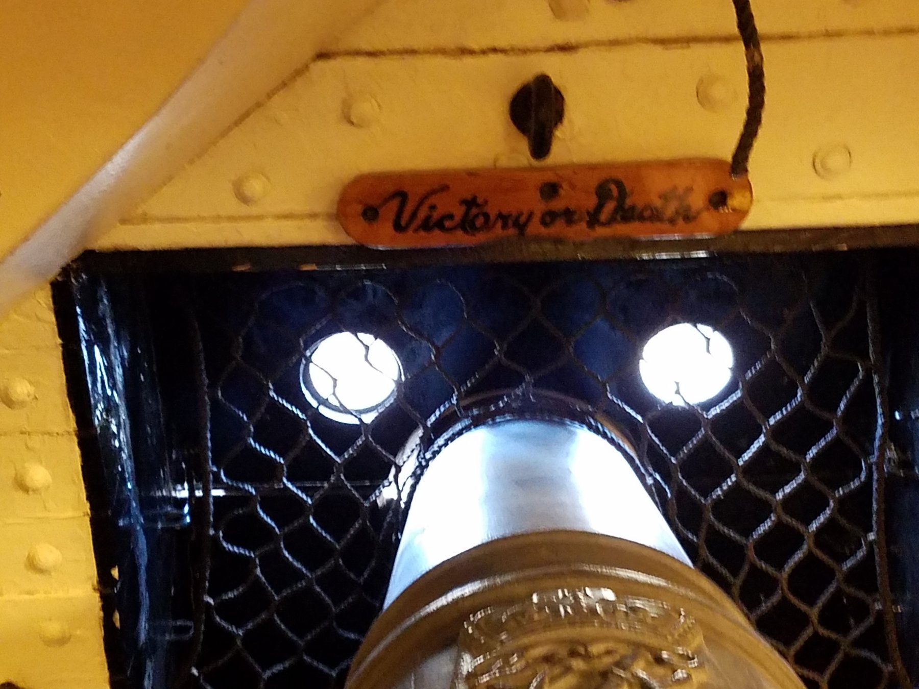
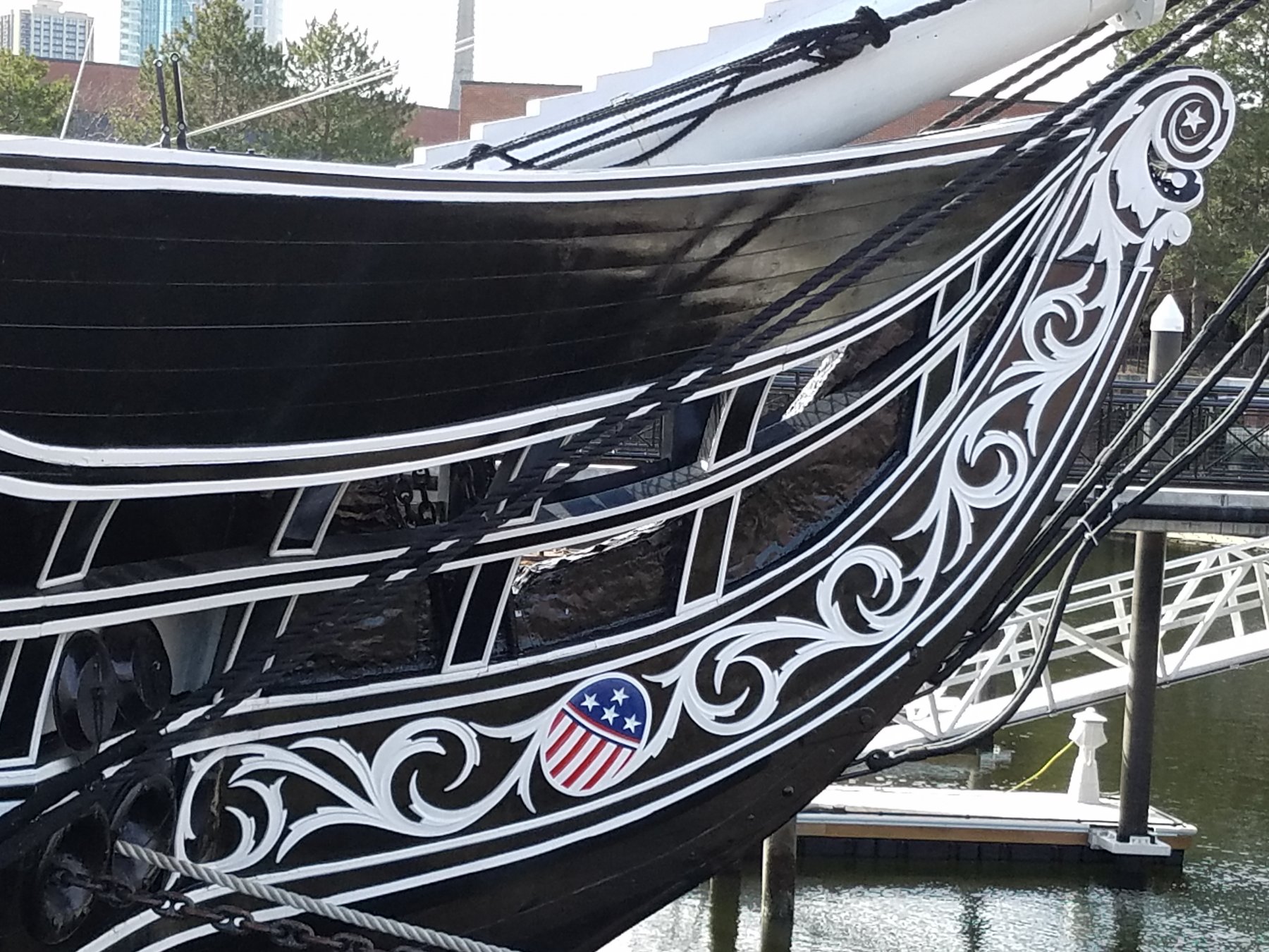
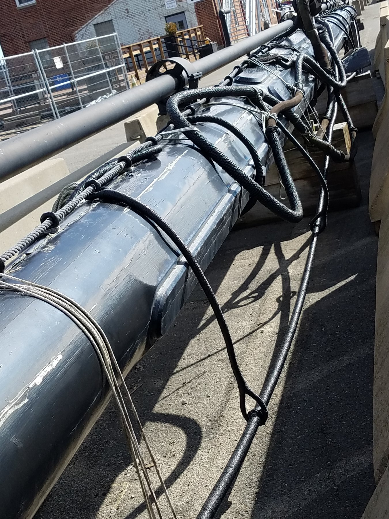
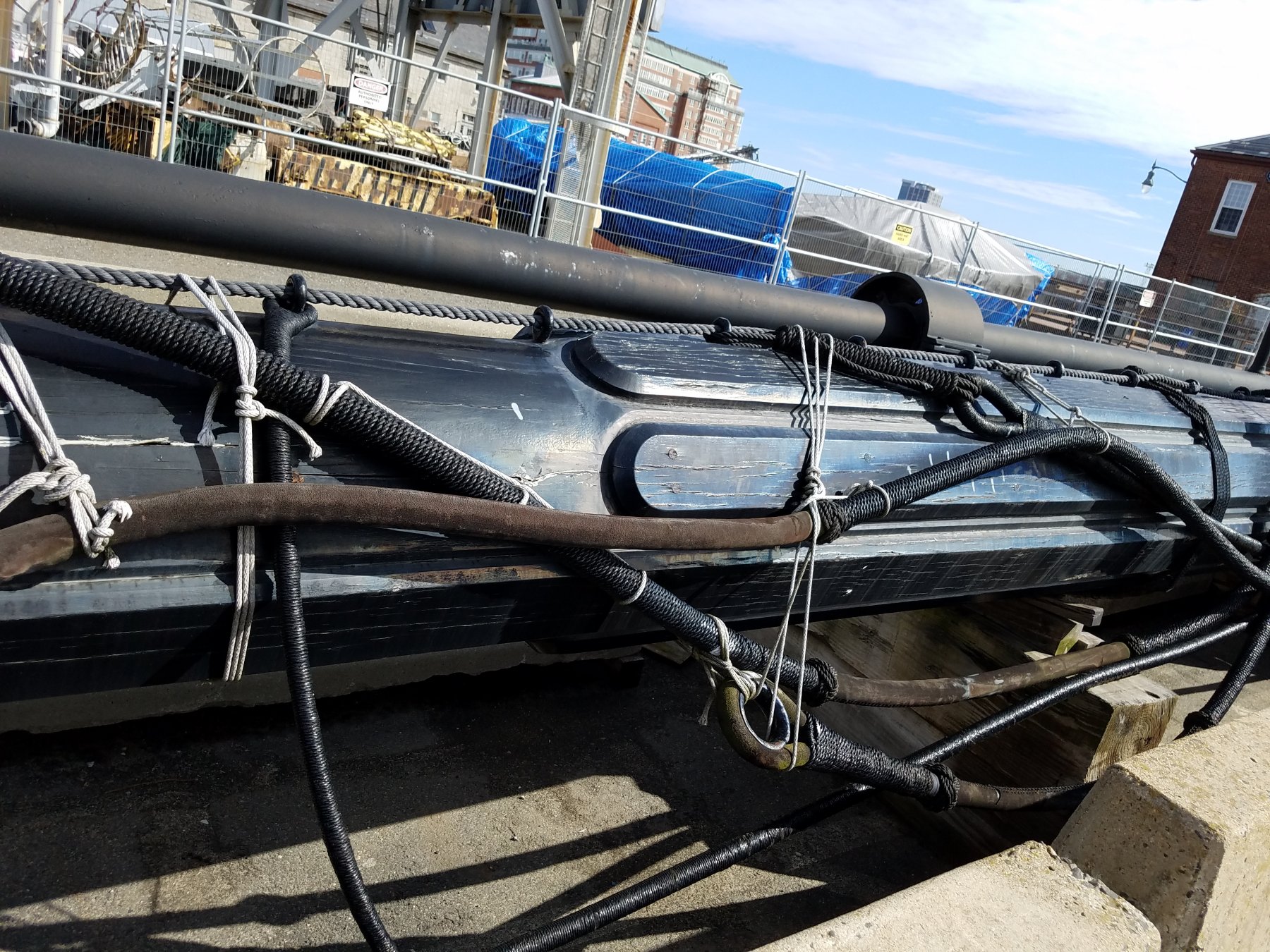
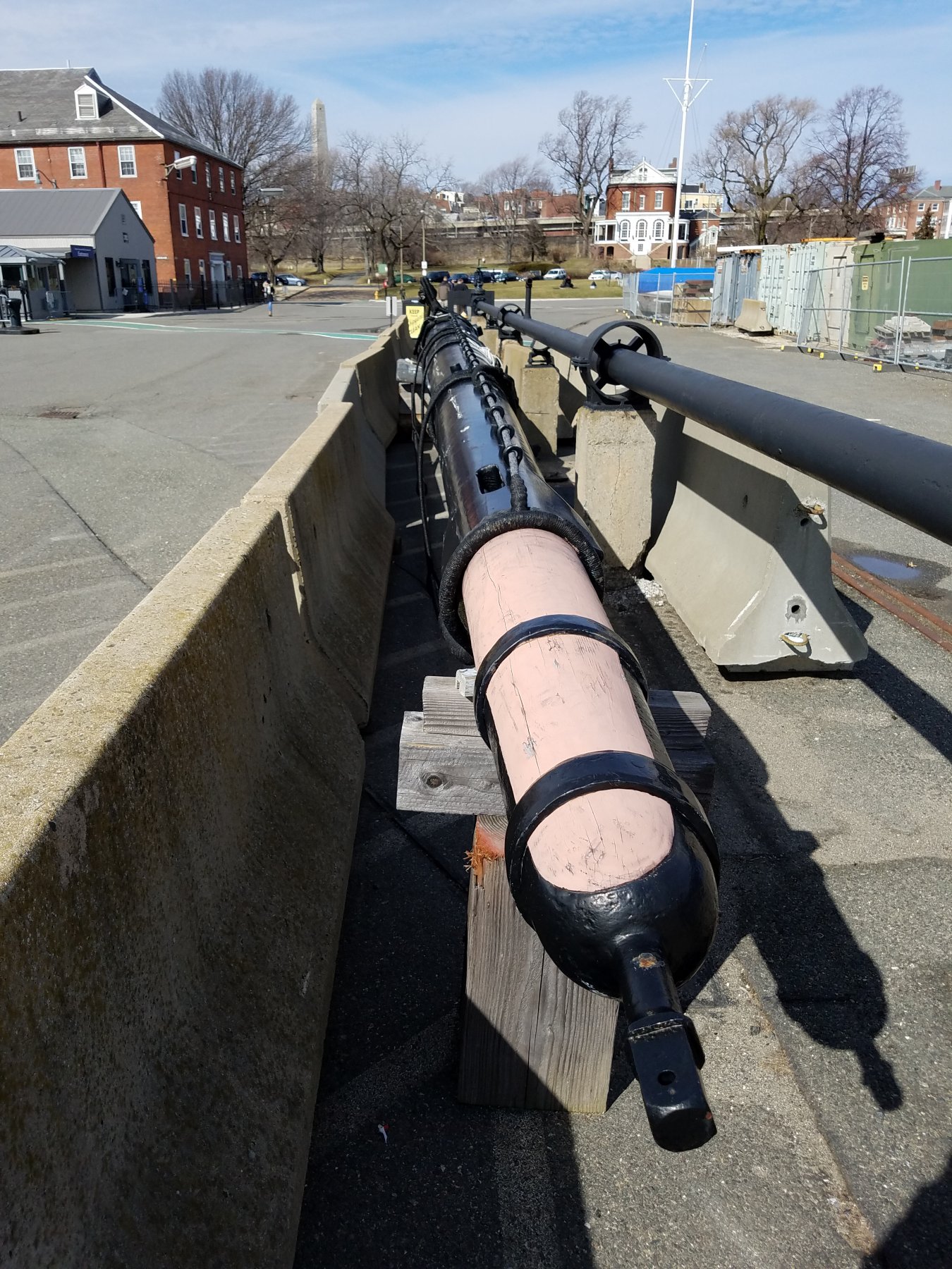
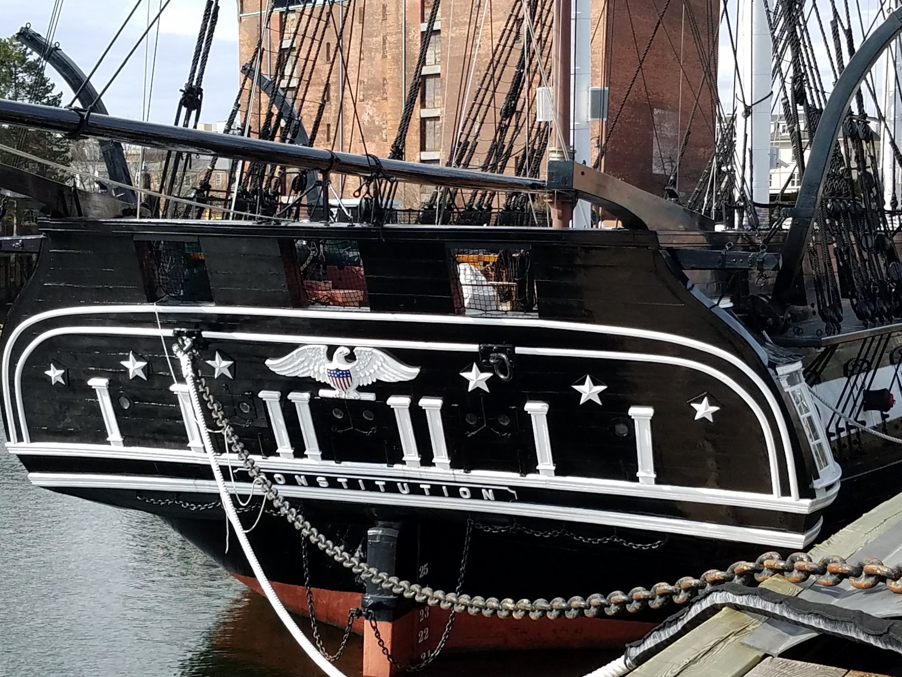
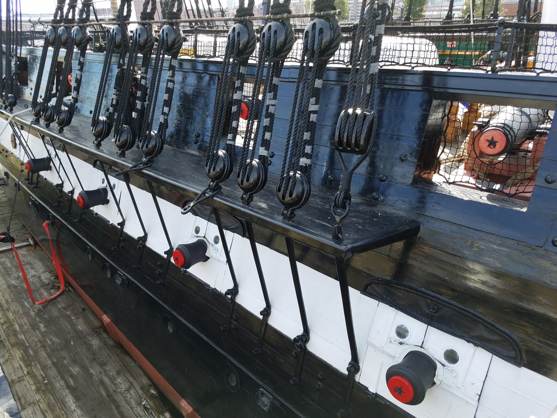
So I was away from the workshop for a bit.. but now I'm back at it. At least until May when I launch the real sailboat. Made some progress. Since I am at the point of working in the gun deck, figured it was time to go to visit The real Connie and take some pictures. (Of the gun deck) She is out of dry-dock from her last round of refit in 2017. Gun-ports from outside Bow scroll work Since they haven't yet put the full rig back up, Several of the spars were on the grown. Very cool to get this close to them! Main Yard And of course the stern windows Guns from inside /Gundeck Victory or Death (It looks yellow in the pic because of flash, but bulwarks are all white!) Hatches/ Stairs and gratings on the gundeck This set of ladders will get modeled. Both the ladders going up to the Spar deck and the ones going down. Those deck beams I made to for the open gratings.... And the real ones This is the ladder that is from the open spar deck grating and the main gun deck hatch under that grating. And just a nice shot looking down the deck to the Great Cabin in the Stern


-
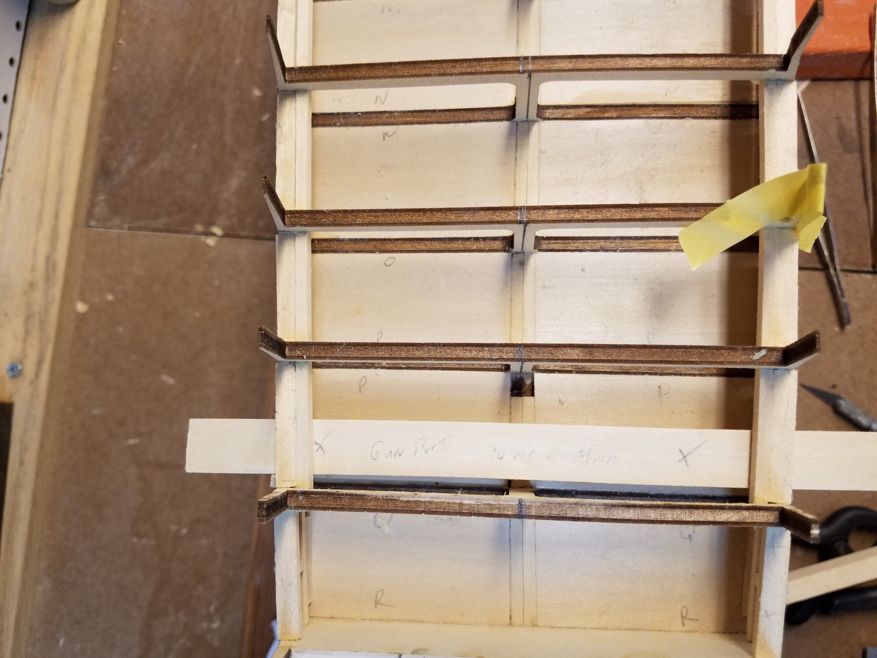
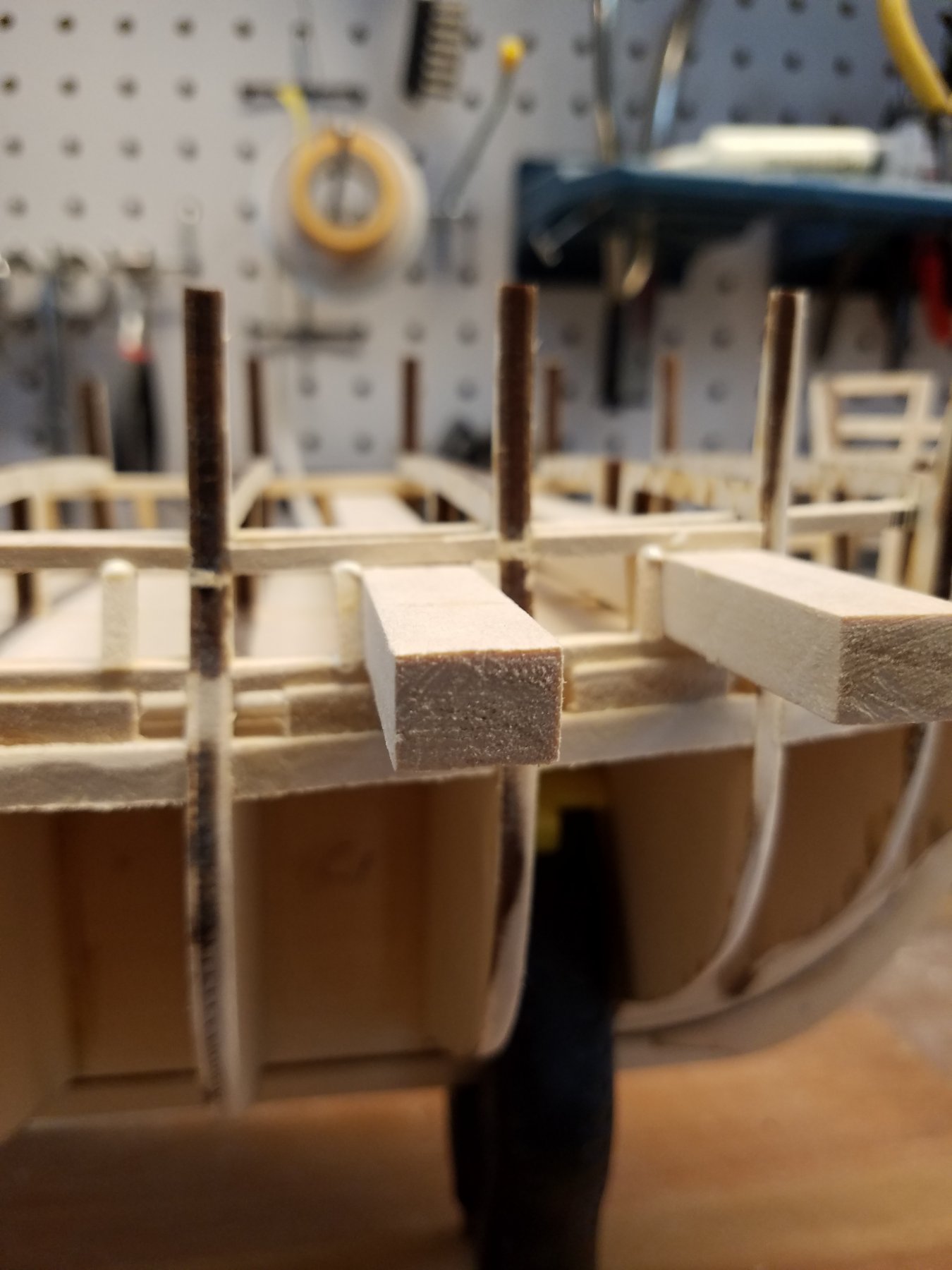
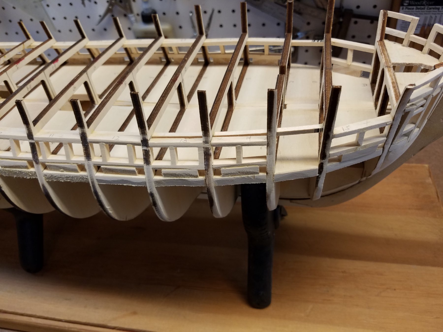
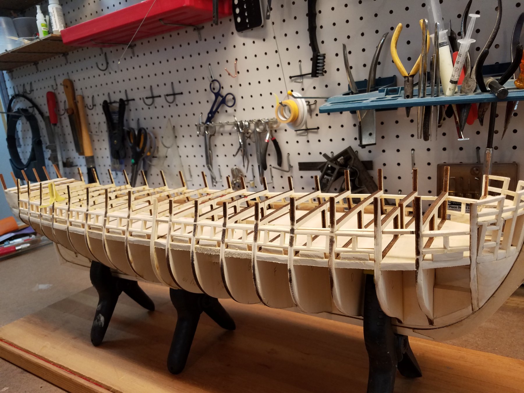
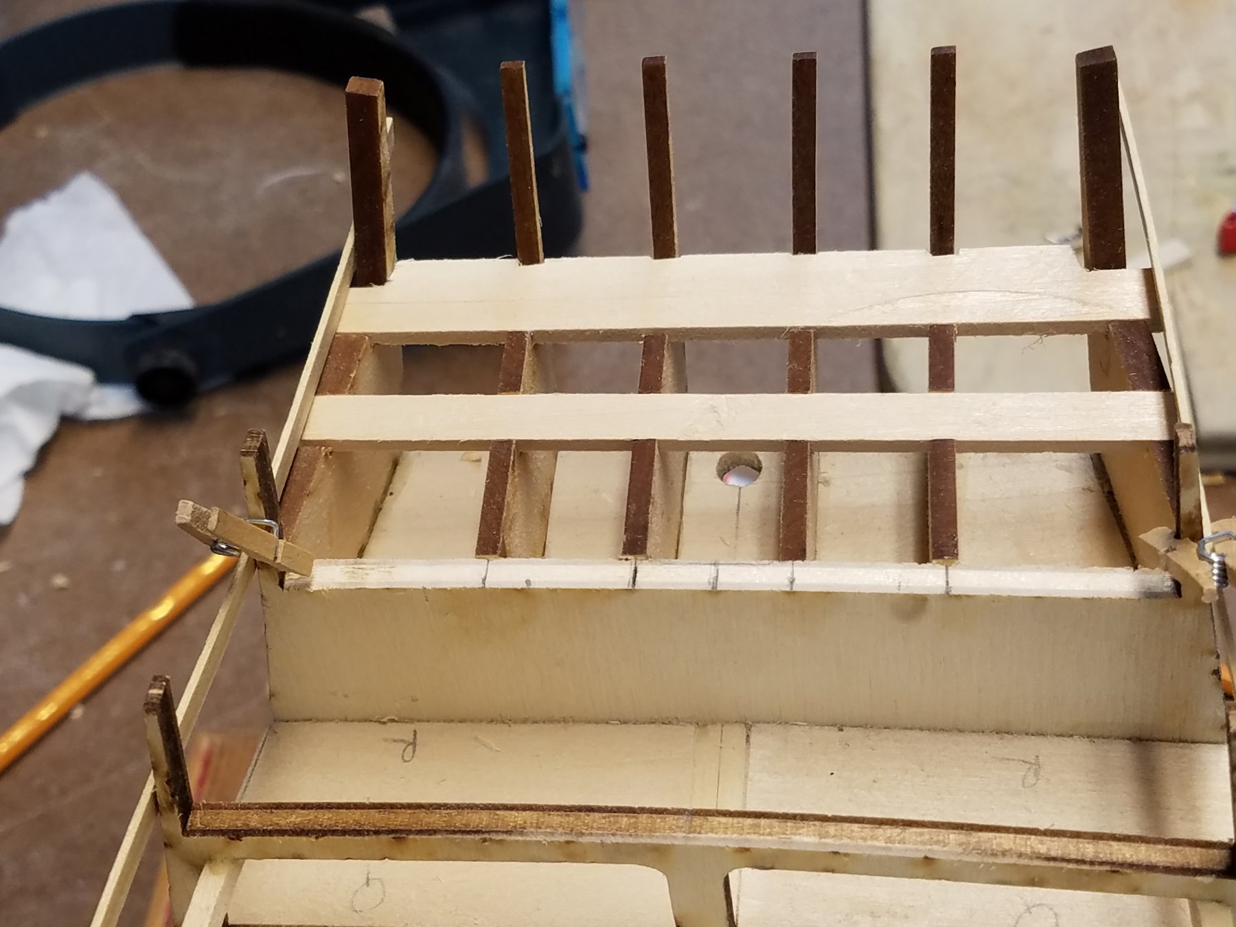
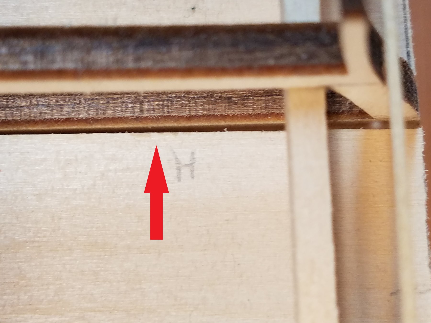
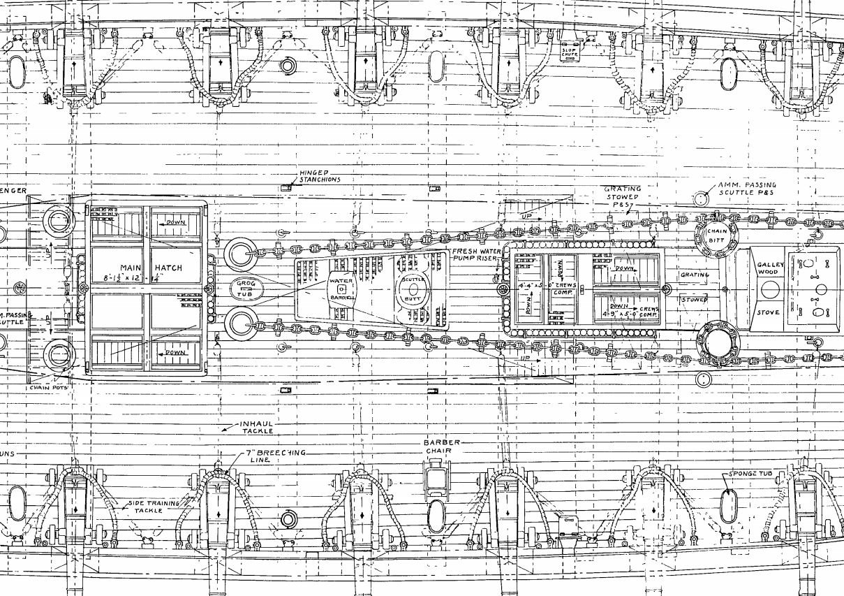
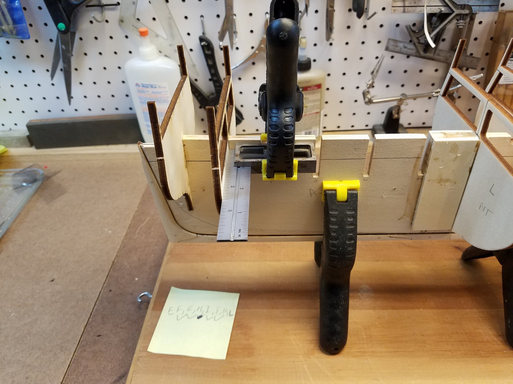
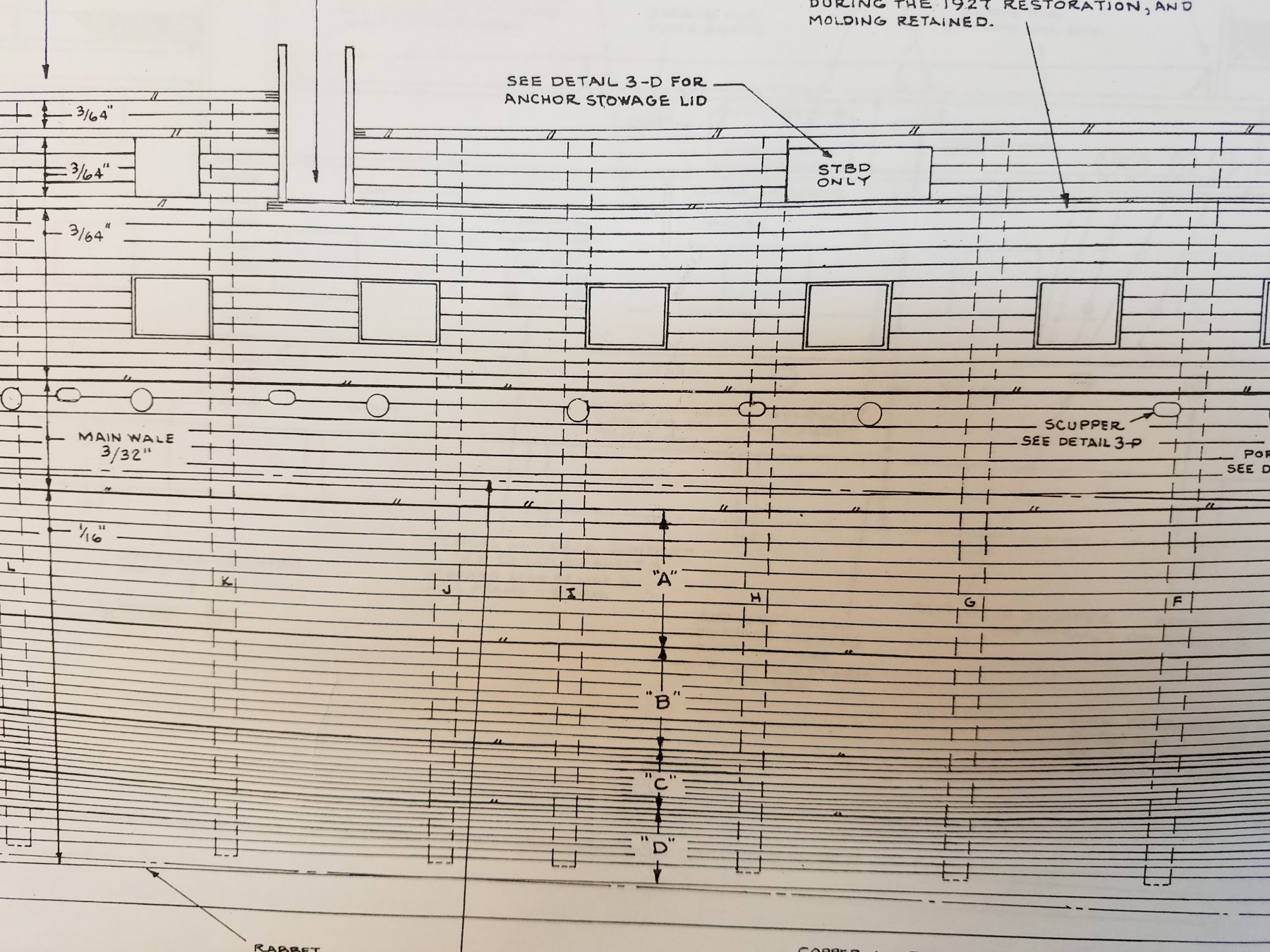
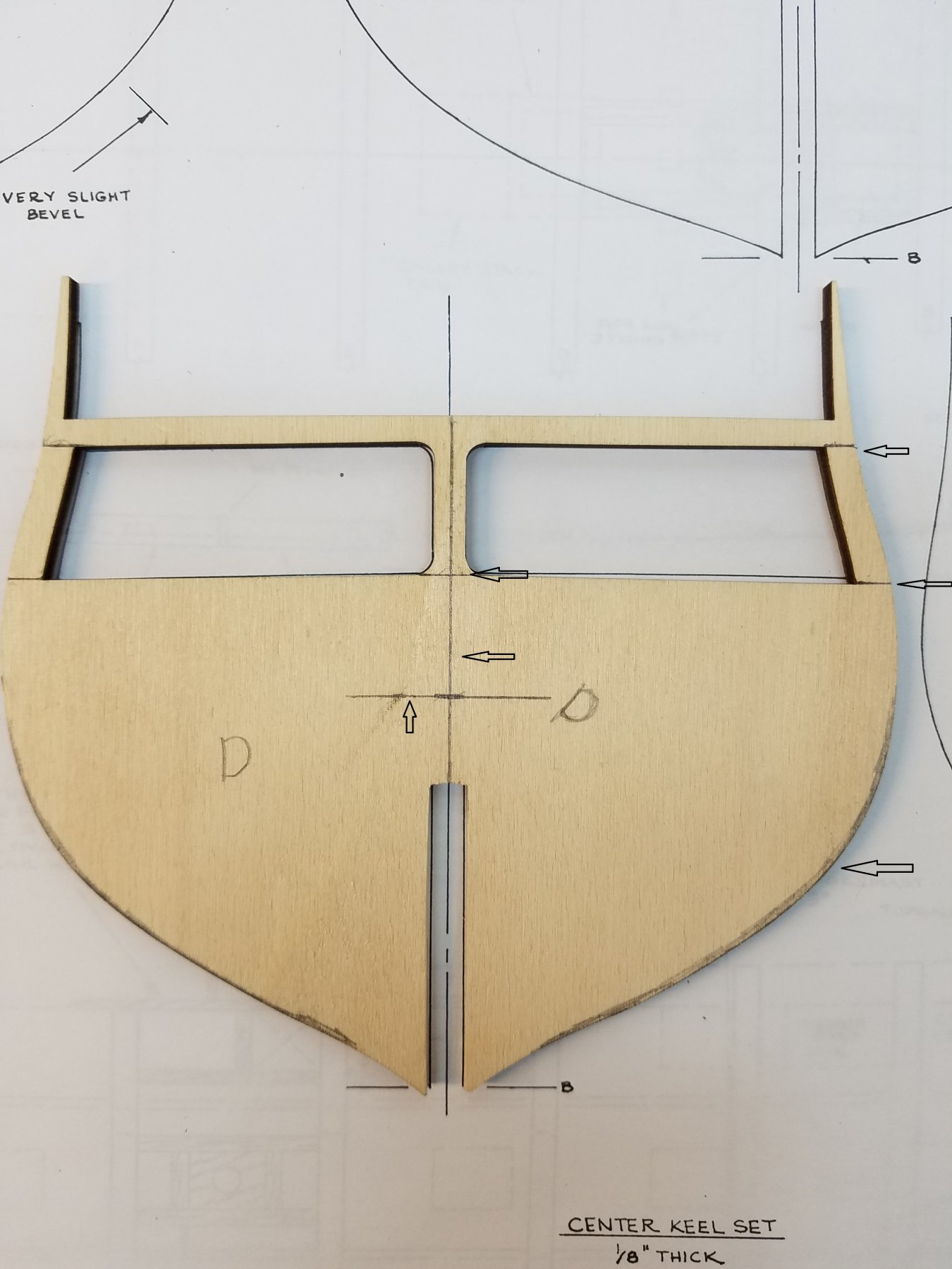
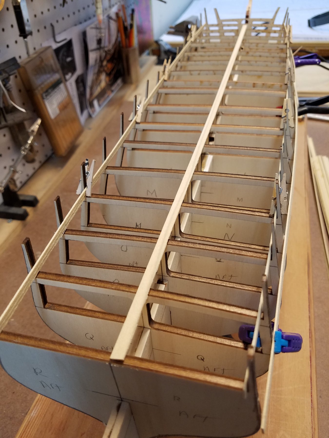
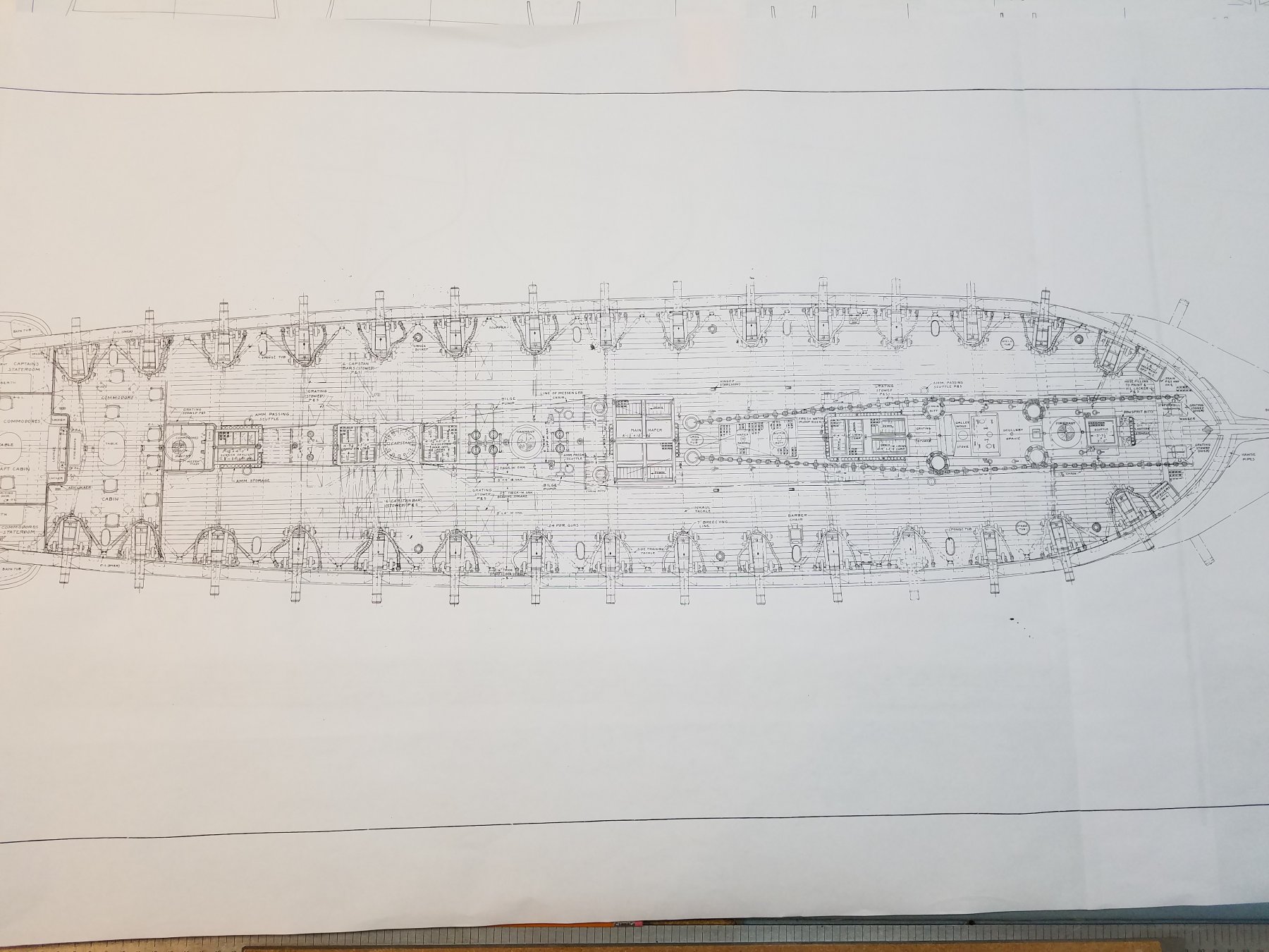
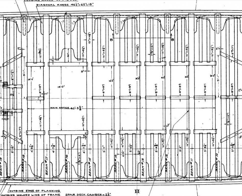
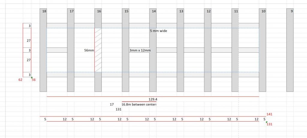
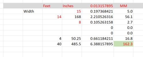
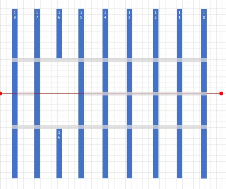
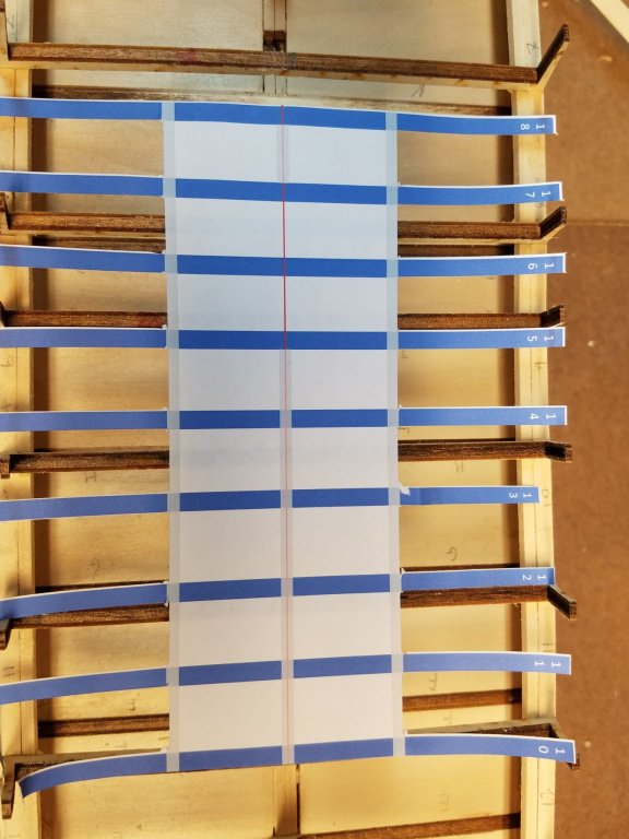
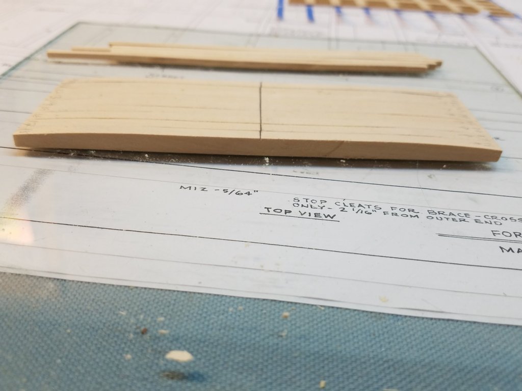
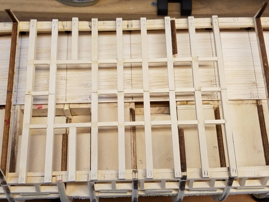
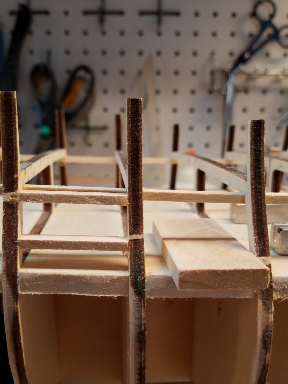
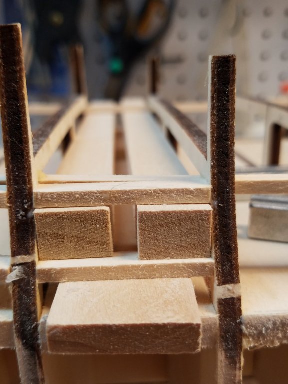
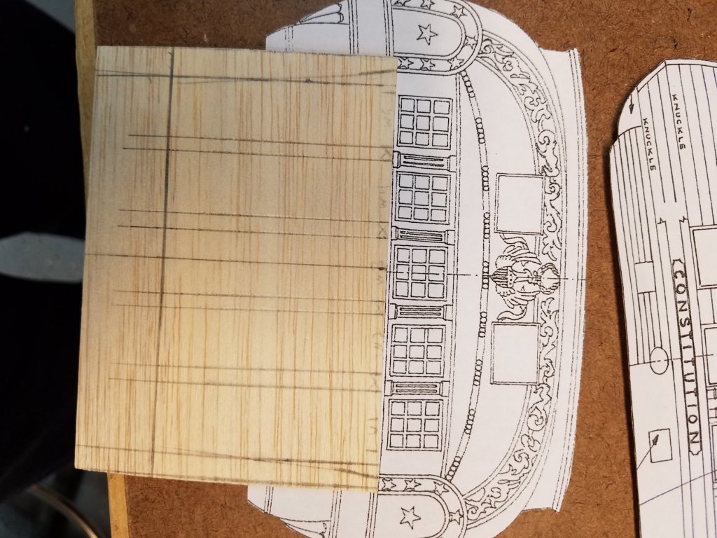
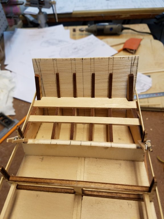
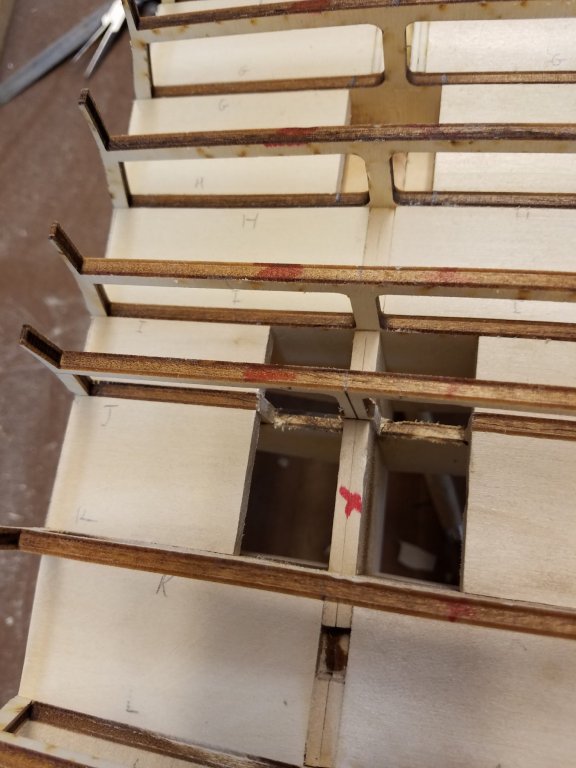
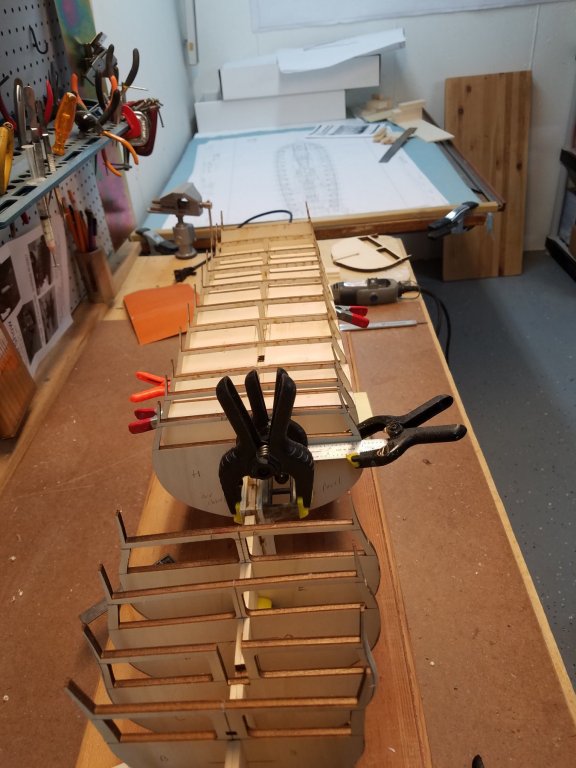
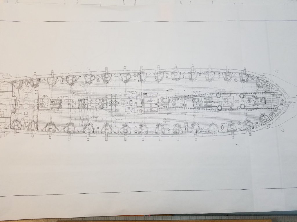
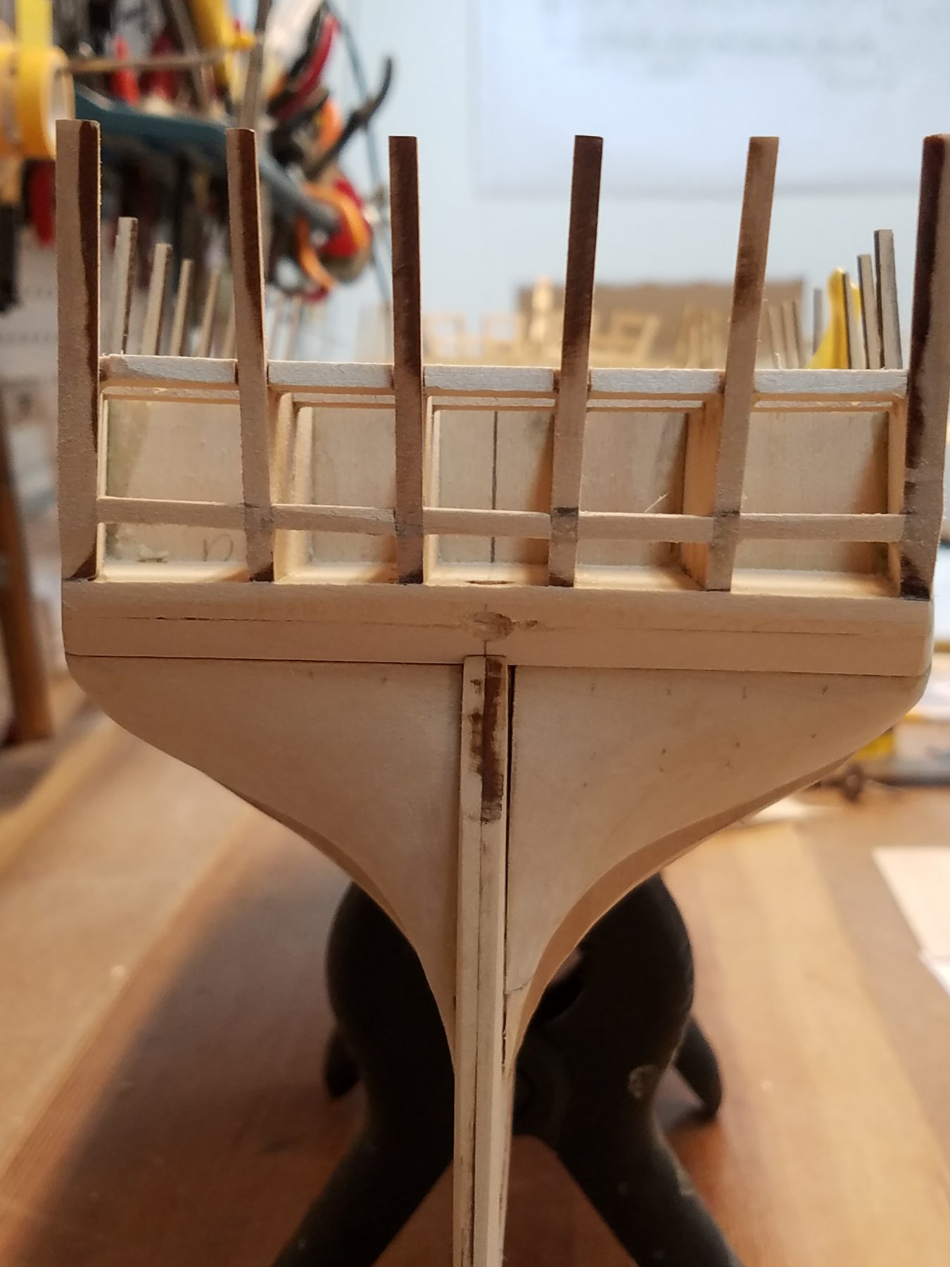
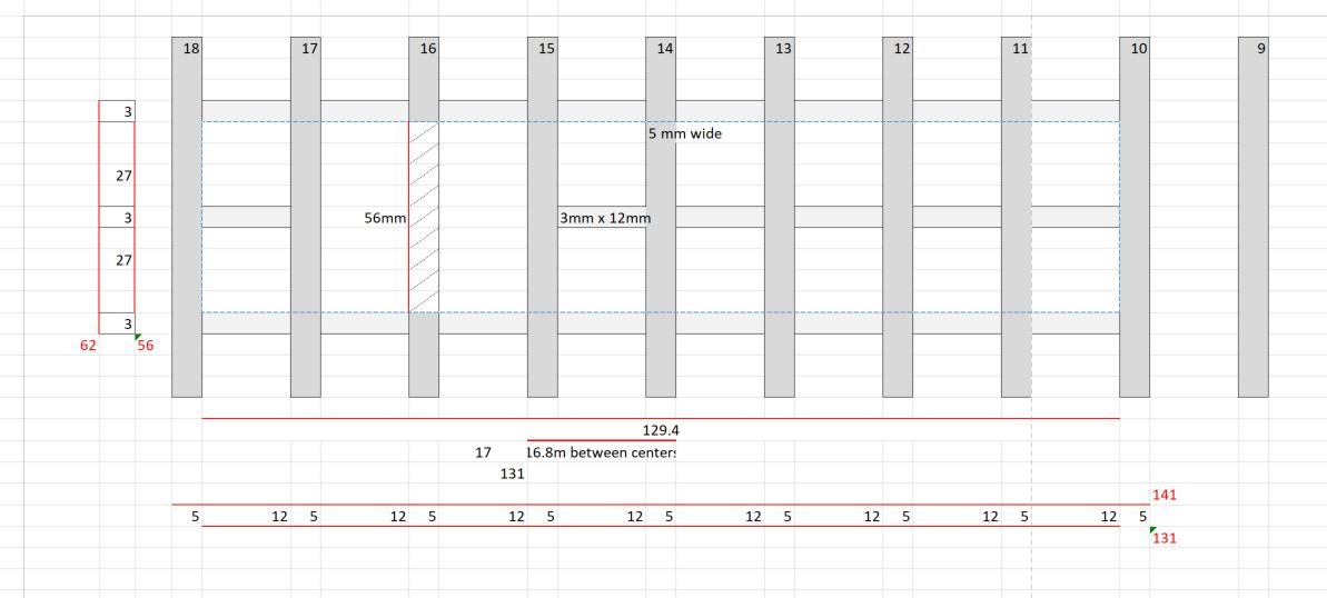
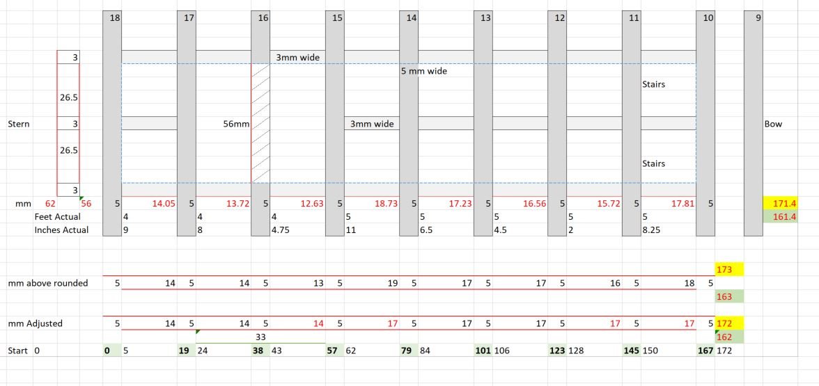
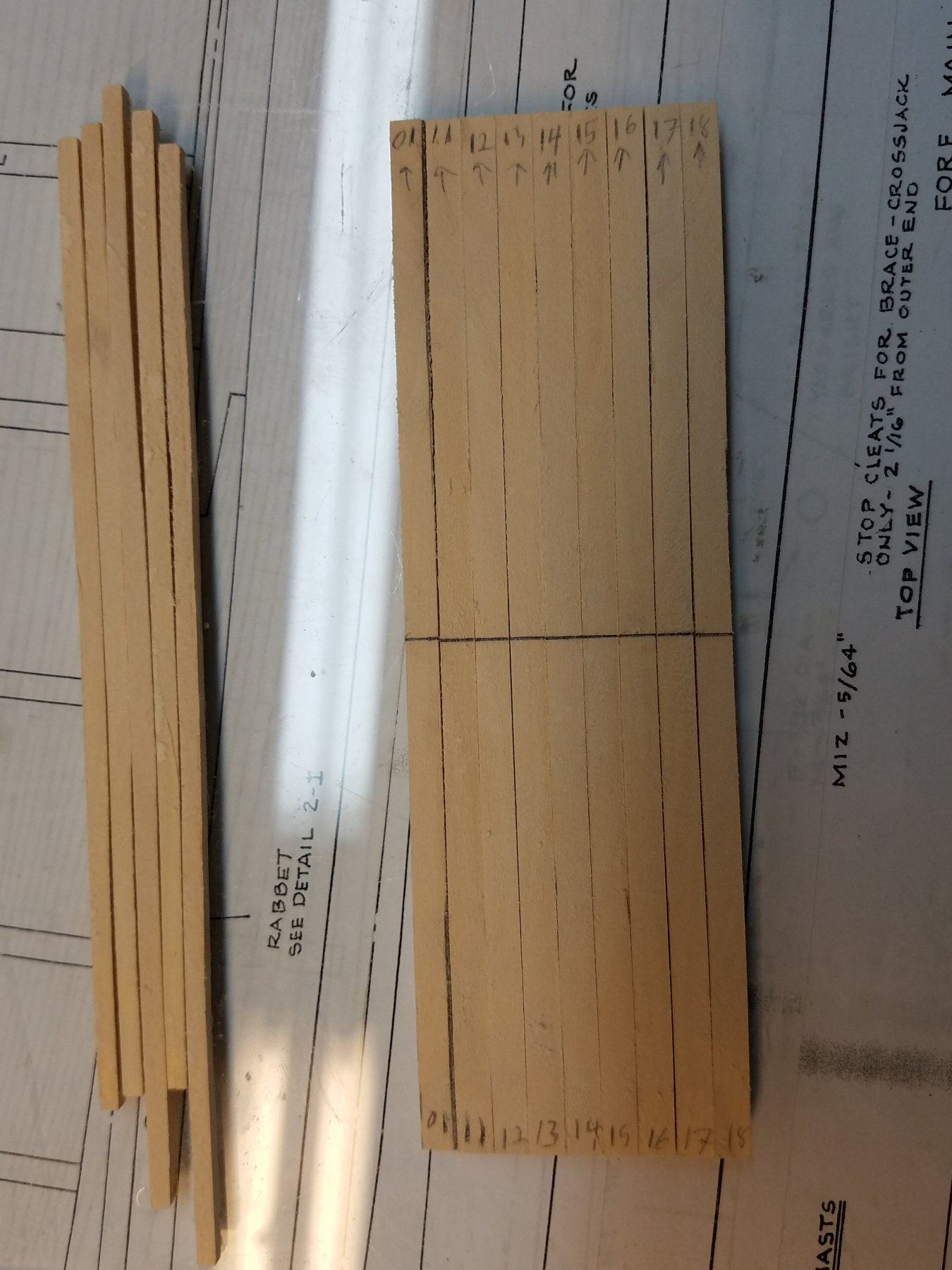
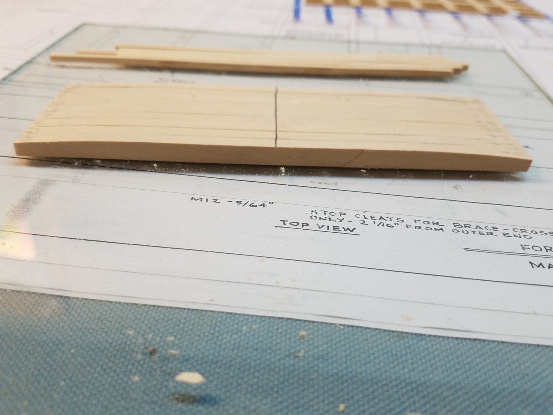
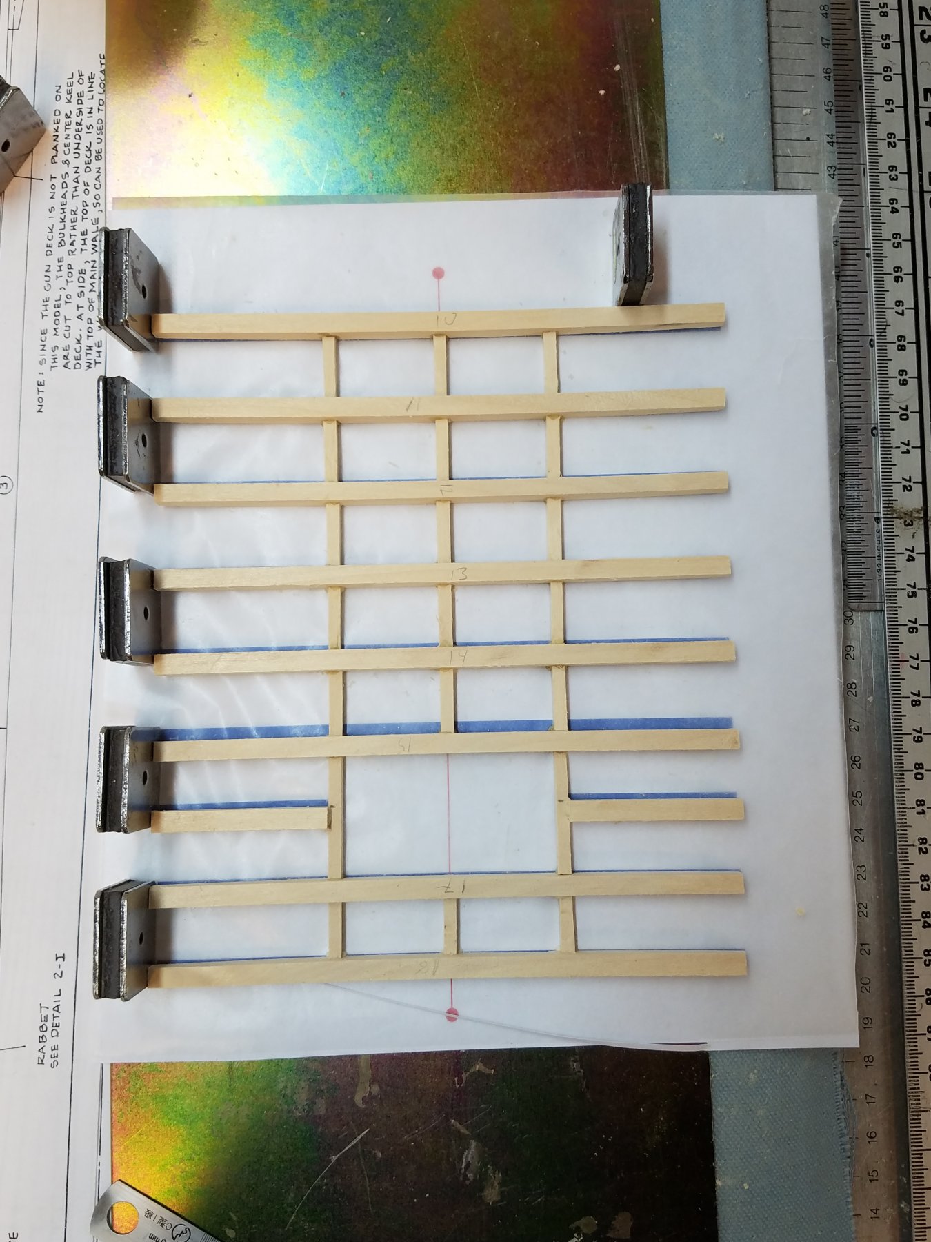
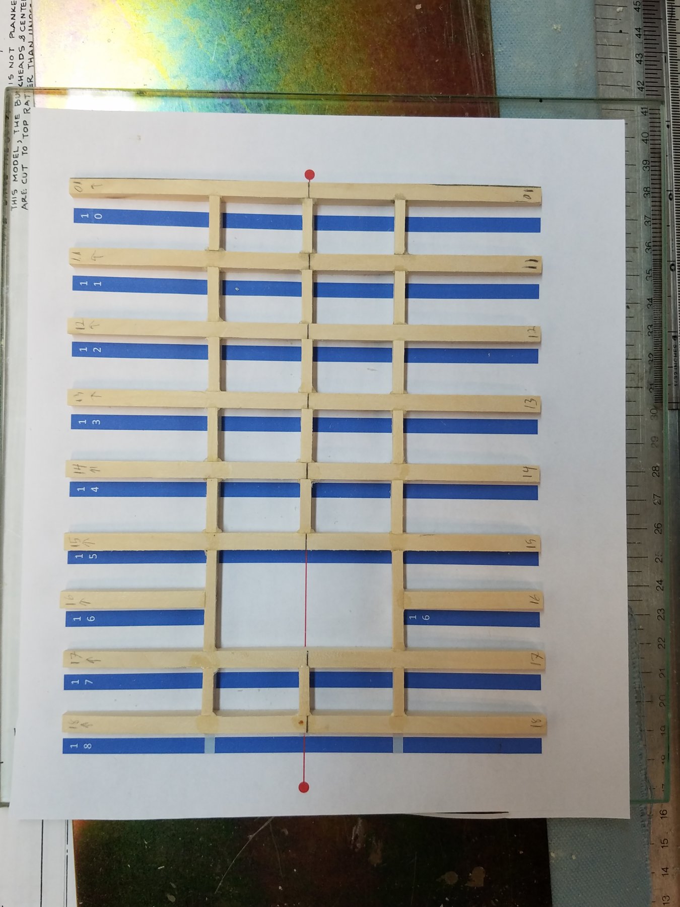
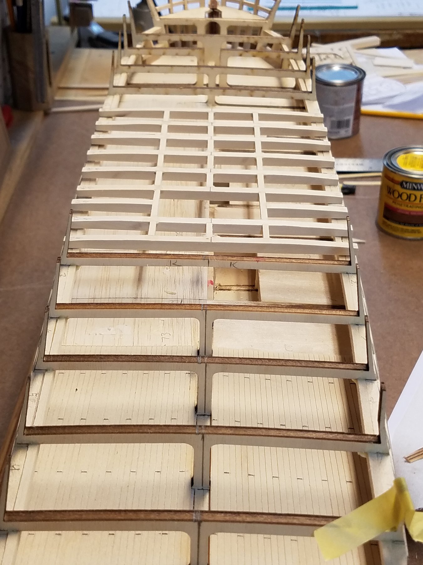
Time for next update. First. Did a bit more on framing the stern windows.. Wow, in the picture , they look, not square, or level. I'll have to check again. They should all be 13 mm high and and level. Hopefully its just the angle of the camera making it look off. The stern does have a curve... As many have pointed out. :-) I've been eager and scared to start to the next part of the build. That is working on the Gun deck. Scared because that means cutting those spar deck beams. At that point I'm committed. Well... I actually had dremel in hand with cutter bit running, about to start cutting, and stopped. One thing that has been bugging me is how will I be able to put in the new beams later, center the hatchways etc without those existing beams as reference points. And to further complicate things: The existing beams as per the kit are not accurate to the real ship. # or location. Since the kit, has the gratings on the spar deck, the beams are never seen, so it doesn't matter. With the open gratings and visible beams.. they need to be reasonable accurate. So after pondering awhile.. (Dremel still in hand running) it hit me... Build the whole spar deck beams, and framing for the open hatches FIRST off the ship. Ensure proper fit,location... Only then cut into the existing beams. Now I had a plan Step 1: From the Connie CD/Planes.. study the Spar deck plans... re:deck beams around the open waist Nn the blueprint above.. if you look close has all sizes and distance between centers of the beams and carlings?. The beams are NOT equally spaced... Step 2: In MS Excel map out my new beam layout Note this lays out the beams and lists the lengths and widths. but Excel not good at making to scale. Also in Excel.. convert from the CD plan measured in actual Feet and inches Convert to right scale 1:76 And then convert to MM in the new scale. (In my models I find it easier to work in metrics ) The number with the green background represents the length inside of the opening (dashed blue line). So from Actual(from blueprint) scaled down is 161.4mm With rounding of all the summed individual lengths is 163mm After some tweaking 162mm The last row labeled mm adjusted is what I actually wound up using. Minor changes.. +- mm here and there. My conversions: Next step is to make a scale drawing. MS Visio Unlike excel can have a metric ruler and print to scale. So I can use the layout and measurements from excel.. to make a to scale version in visio. Next, I printed out the visio and used it as a template to verify on the mode. It took a few iterations and tweaking to get the right.l Milled some basswood for the new beams and cross pieces. Used the existing beam to get the right camber of the deck And then glued it up using the printed visio template shifted so you can see the template Just placed on the model on top of existing beams to verify all looks good. NOW I can safely cut out the exiting deck beams. Went back to the Dremel... with cutting disk and started surgery. Note I started at bulkhead E. On E I cut only the center support but left the original beam in F,G,H,I,J I cut out the beams On K I also cut the center support but not the beam. Also note... Prior in the build I put a ran a 2x2mm strip of wood under all the deck beam in preparation for this. (To support the new beams.) Those turned out to be level with the top of the gun port header as well. You can see this below. And now, With the new beams just set in place (No glue): You might have notices I also started making templates for the Gun Deck deck. I'll save that for the next post. probably next weekend.


-
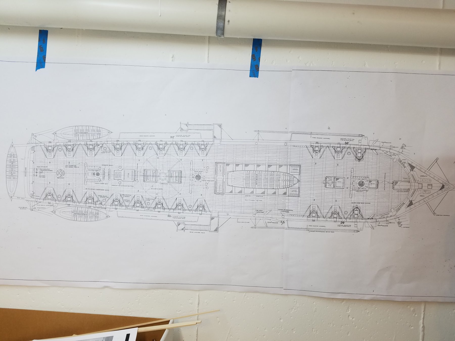
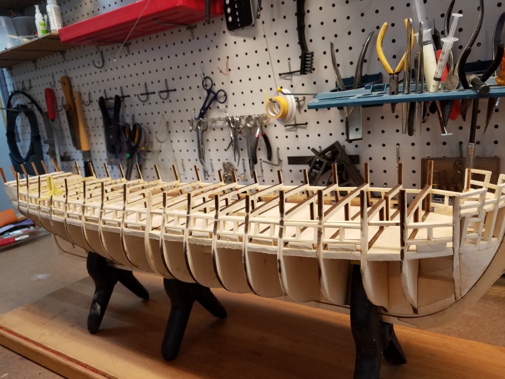
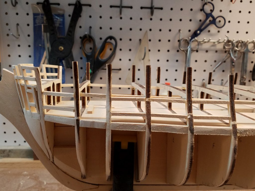
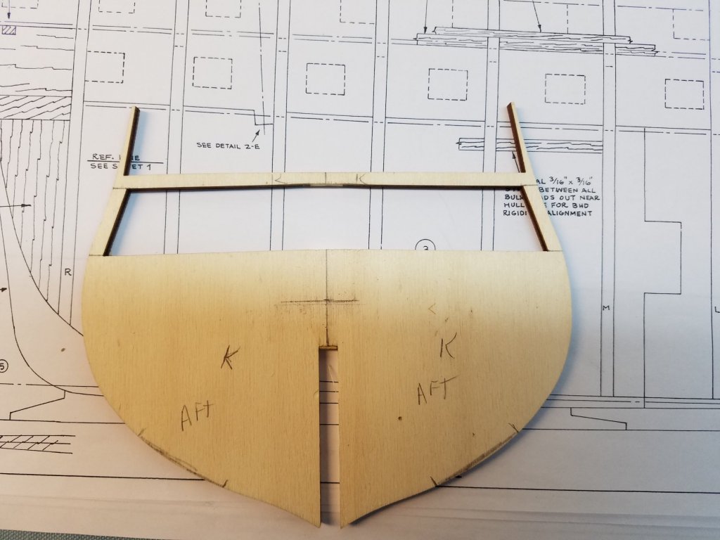
TigerSteve: The grain on that particular piece doesn't really matter as its a Jig only used to space the stern pieces. Wont actually be used on the model. JS Gerson: I did the same as you. went and checked the Connie CD with the historic and restoration plans.. Also, I was looking at your log today.. Saw the discussion on the stern. Along with Cpt Steve's comments. By luck maybe... I didn't have the curve problem.. or I should say I dealt with it without seeing it as an issue. As you mention, the transom block is curved. But the 4 stern pieces are identical. When I was fitting those 4 (6 if you include the 2 outside pieces) As I was fitting them, I trimmed the end of each one (the side toward the bulkhead) so that the bottom outer edge lined up with the stern block edge. And thus all six of the stern pieces followed the intended curve. Now I'm not detailing the Great Room / Captains Quarters as you ans Steve are........ (But then again...maybe its not to late to re-consider ;-) Sooo... Today the wife was out of the house the entire day. That means I got to spend the whole day in the shop!! Excellent! And back to the gun port spacing issue. And I have an answer.... :-) The diagrams in the AOS book are too small to decern any difference. The various ME plans are all consistent in that the spacing is inconsistent. (Although the ME plans are consisting among each of the sheets (if that makes sense) So I went to the plans off the CD. Awhile back I had the ones for the Gun deck printed ...scaled up bigger than the ME Plans. and taped to my wall actually. (How did I miss that !) On this plan in the larger scale is was clear that the spacing was Inconsistent. Some minor. some not so minor. I was also looking at another view of the ship from the CD to compare. Its a historic line drawing showing the profile of the ship with all the masts and rigging. I believe the port locations are adjusted to avoid the shrouds and dead eyes on the chain plates. So with that figured out. I'm just going to follow the spacing as layed out on the ME plans afrer all. So back into the workshop.. With the entire day to myself. I finished framing all 30 gun ports on the gun deck. In progress Basically working 4 at a time... two on each side Only trick was that the sides of the ship have some tumble-home. And the amount of tumble home changes over the lenght of the ship So while the length of all the pieces were consistent (10mm). I had to cut both ends at angles (not square) for sections where the tumble home was significant The end cuts varied from 5 - 35 degrees. After doing a few , I got into a rhythm .. they actually went a lot faster than I expected. After I finished them, let the glue set for a few hours then sanded them all down to be fair with the frames ahhhh ...Nice square gun ports. My OCD at work :-) Now back to work tomorrow. And the work week to think about and plan..what to tackle next weekend K
.thumb.jpg.2d1125399c28f0ef72e069d5f374213b.jpg)


-
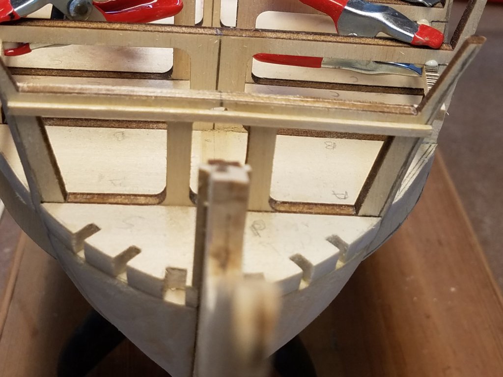
Used2sail. Thanks for the tip. You just saved me a future mistake. I went and checked. You were right. No curve in the top of the forward gun header. Put a batton on it and the flat spot jumped right out. Easy to fix now. Would have been a major pain to fix had i planked it
-
Nikbud, Welcome. Your off to a great start. Your planking turned out beautiful. Even more Impressive considering its your first wood build. I'll pull up a chair and follow your build. Ken
-
TigerSteve: The grain on that particular piece doesn't really matter as its a Jig only used to space the stern pieces. Wont actually be used on the model. JS Gerson: I did the same as you. went and checked the Connie CD with the historic and restoration plans.. Also, I was looking at your log today.. Saw the discussion on the stern. Along with Cpt Steve's comments. By luck maybe... I didn't have the curve problem.. or I should say I dealt with it without seeing it as an issue. As you mention, the transom block is curved. But the 4 stern pieces are identical. When I was fitting those 4 (6 if you include the 2 outside pieces) As I was fitting them, I trimmed the end of each one (the side toward the bulkhead) so that the bottom outer edge lined up with the stern block edge. And thus all six of the stern pieces followed the intended curve. Now I'm not detailing the Great Room / Captains Quarters as you ans Steve are........ (But then again...maybe its not to late to re-consider ;-) Sooo... Today the wife was out of the house the entire day. That means I got to spend the whole day in the shop!! Excellent! And back to the gun port spacing issue. And I have an answer.... :-) The diagrams in the AOS book are too small to decern any difference. The various ME plans are all consistent in that the spacing is inconsistent. (Although the ME plans are consisting among each of the sheets (if that makes sense) So I went to the plans off the CD. Awhile back I had the ones for the Gun deck printed ...scaled up bigger than the ME Plans. and taped to my wall actually. (How did I miss that !) On this plan in the larger scale is was clear that the spacing was Inconsistent. Some minor. some not so minor. I was also looking at another view of the ship from the CD to compare. Its a historic line drawing showing the profile of the ship with all the masts and rigging. I believe the port locations are adjusted to avoid the shrouds and dead eyes on the chain plates. So with that figured out. I'm just going to follow the spacing as layed out on the ME plans afrer all. So back into the workshop.. With the entire day to myself. I finished framing all 30 gun ports on the gun deck. In progress Basically working 4 at a time... two on each side Only trick was that the sides of the ship have some tumble-home. And the amount of tumble home changes over the lenght of the ship So while the length of all the pieces were consistent (10mm). I had to cut both ends at angles (not square) for sections where the tumble home was significant The end cuts varied from 5 - 35 degrees. After doing a few , I got into a rhythm .. they actually went a lot faster than I expected. After I finished them, let the glue set for a few hours then sanded them all down to be fair with the frames ahhhh ...Nice square gun ports. My OCD at work :-) Now back to work tomorrow. And the work week to think about and plan..what to tackle next weekend K 116678001.pdf
-
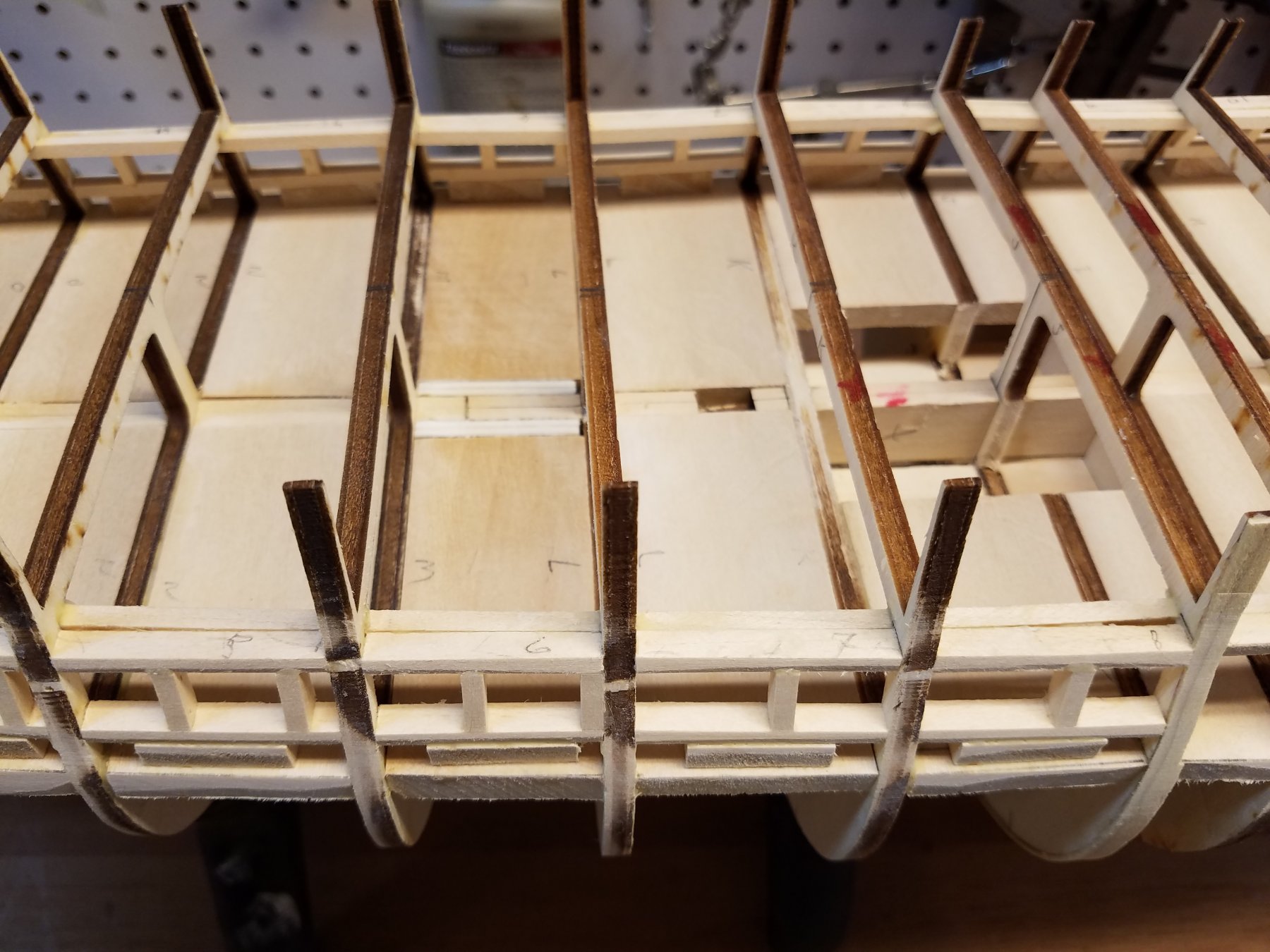
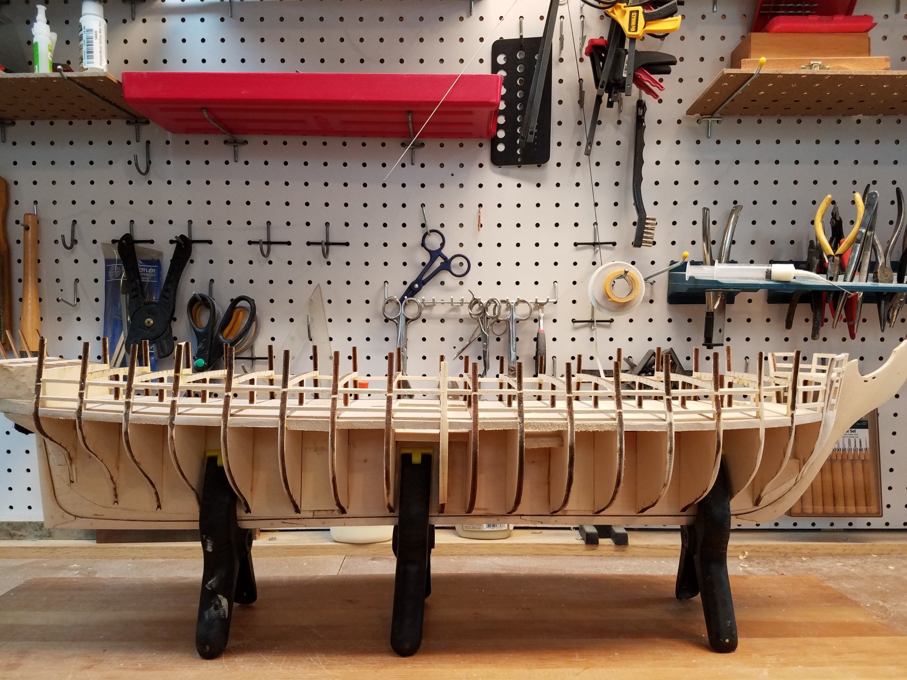
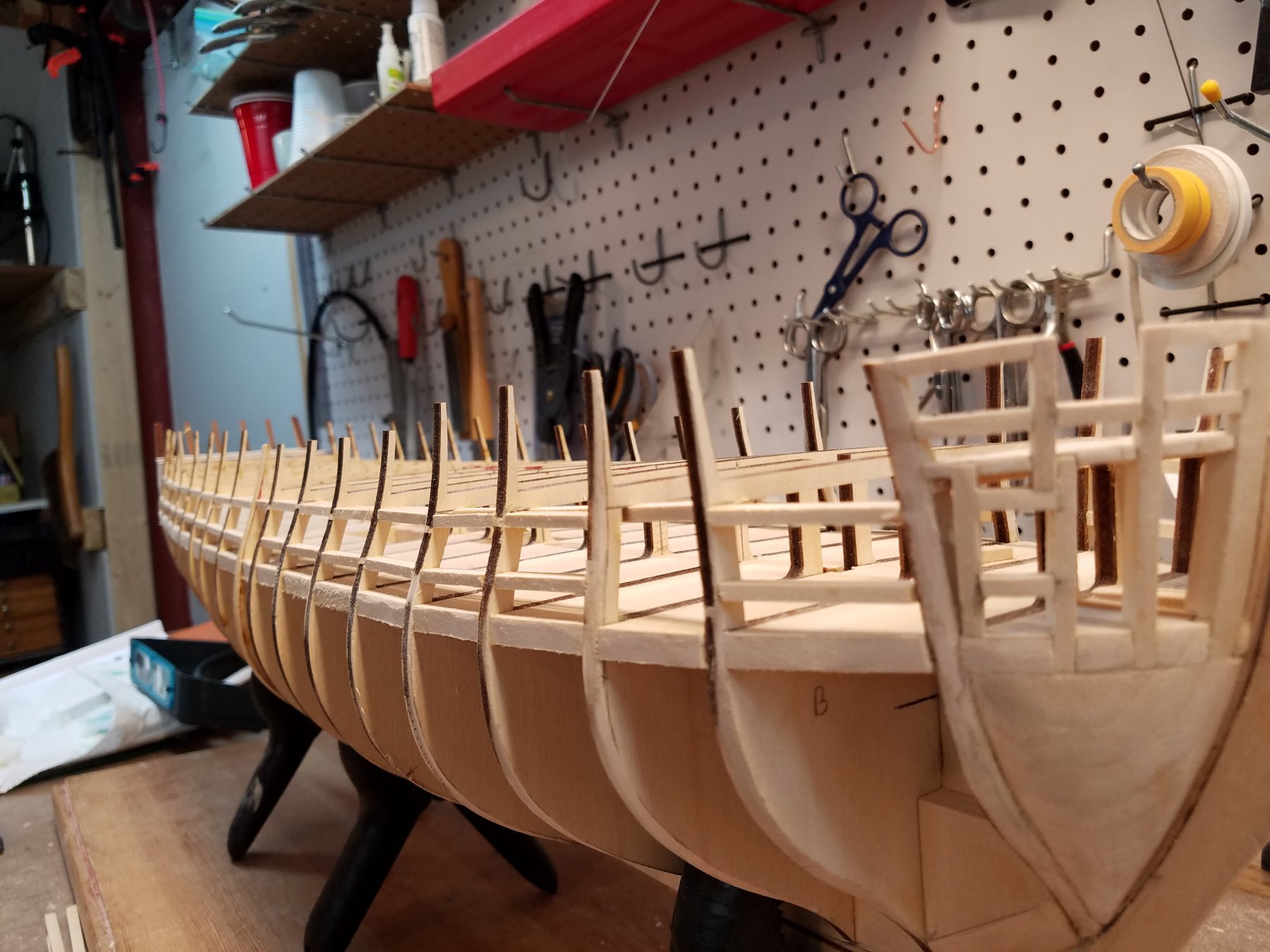
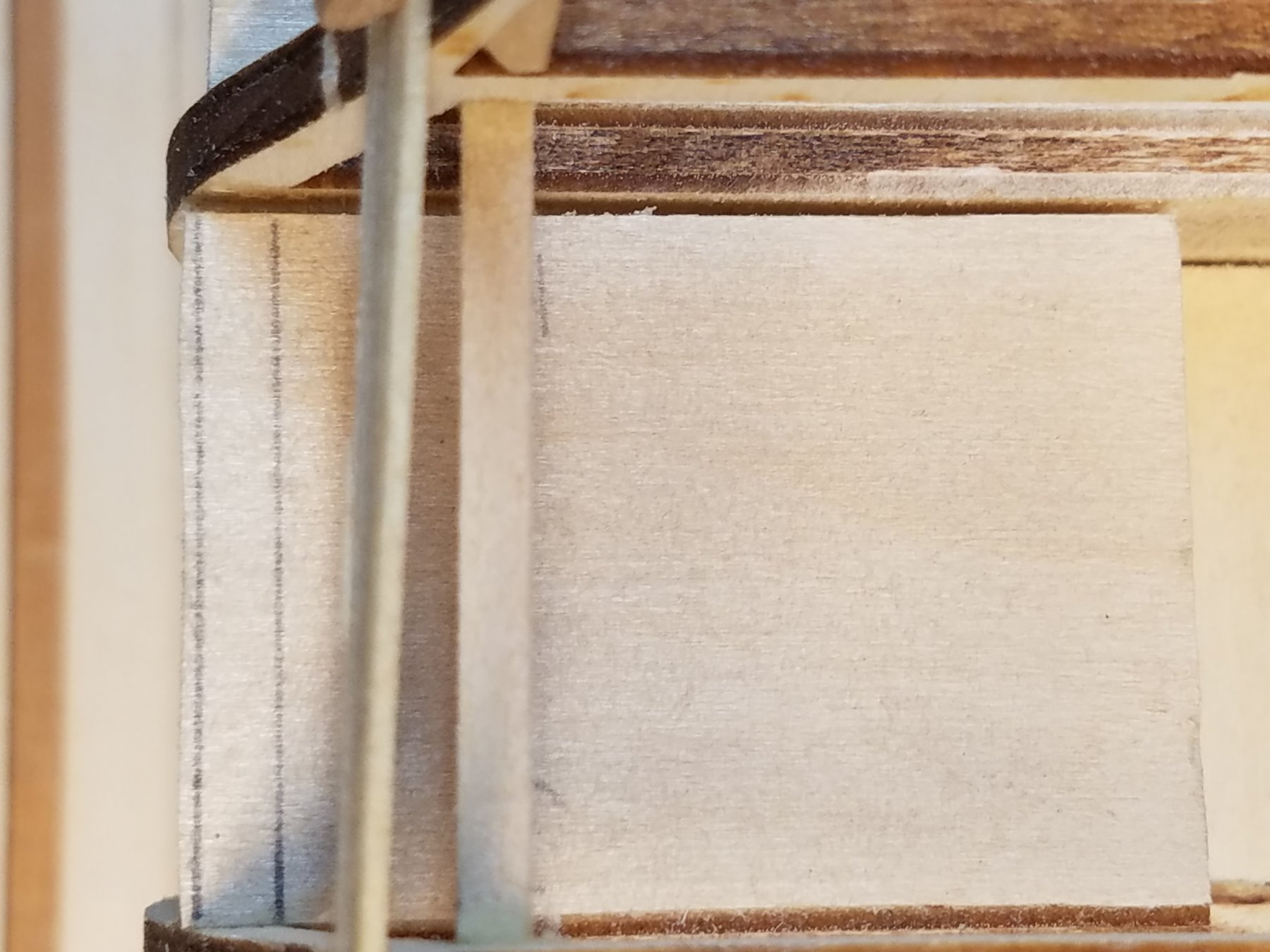
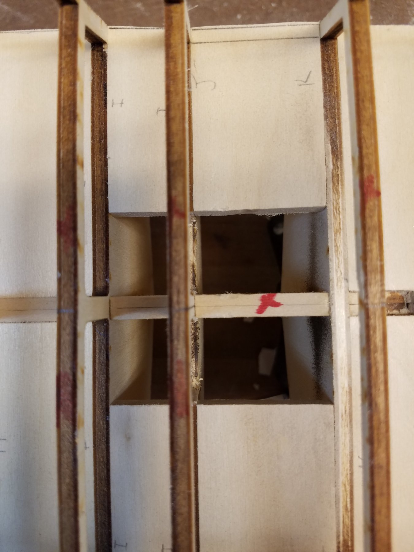
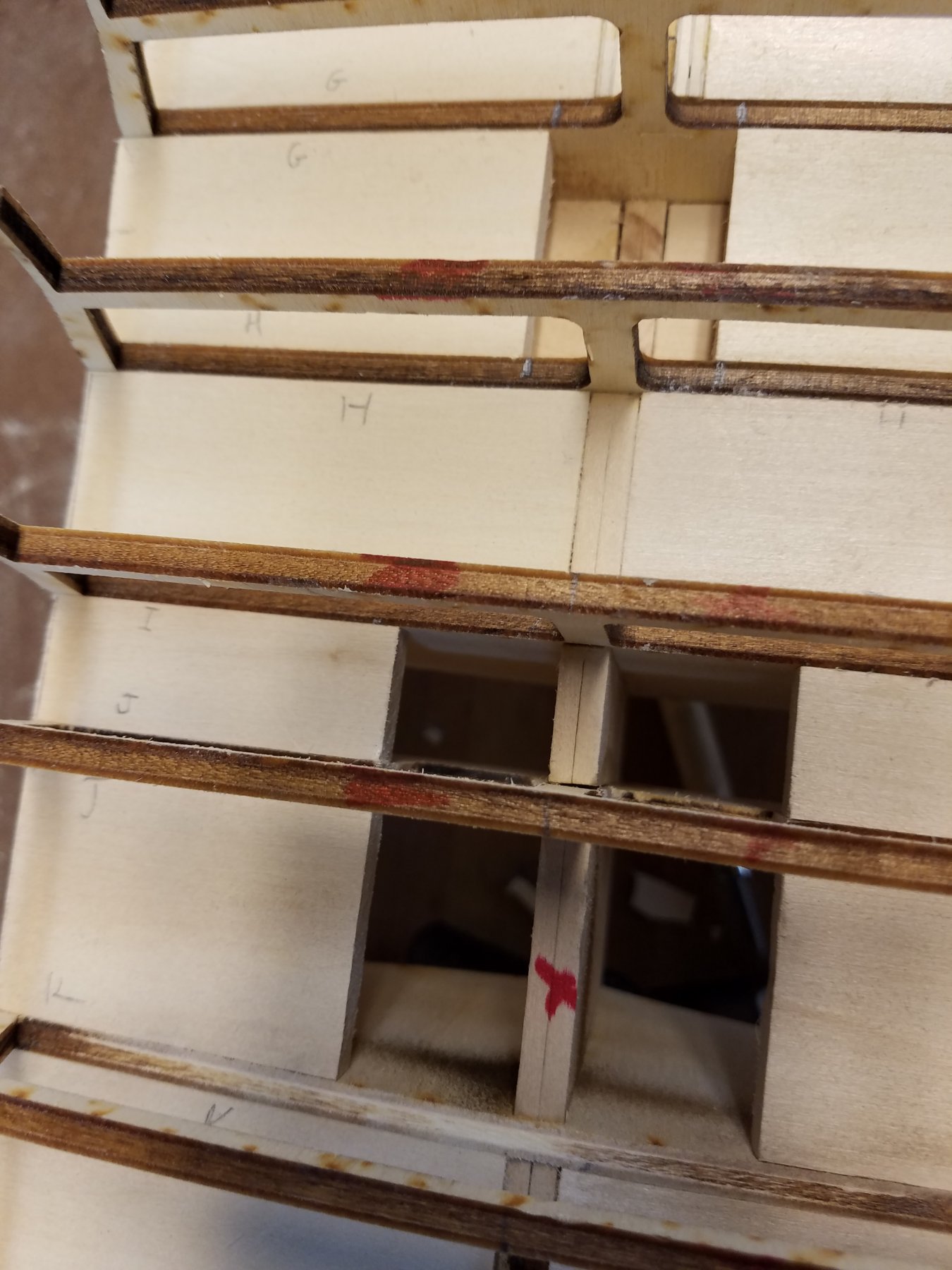
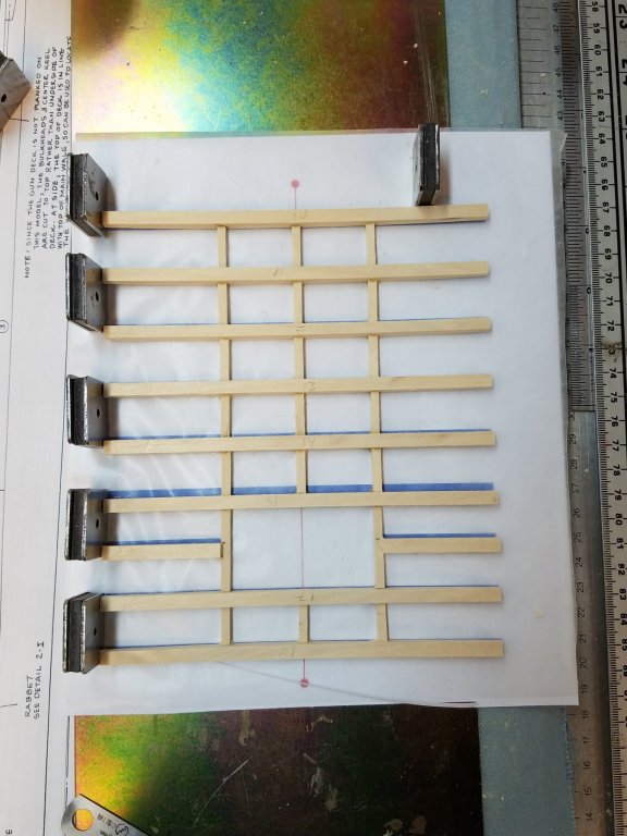
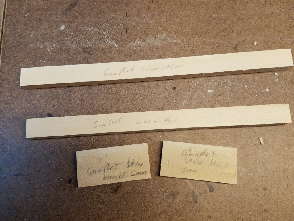
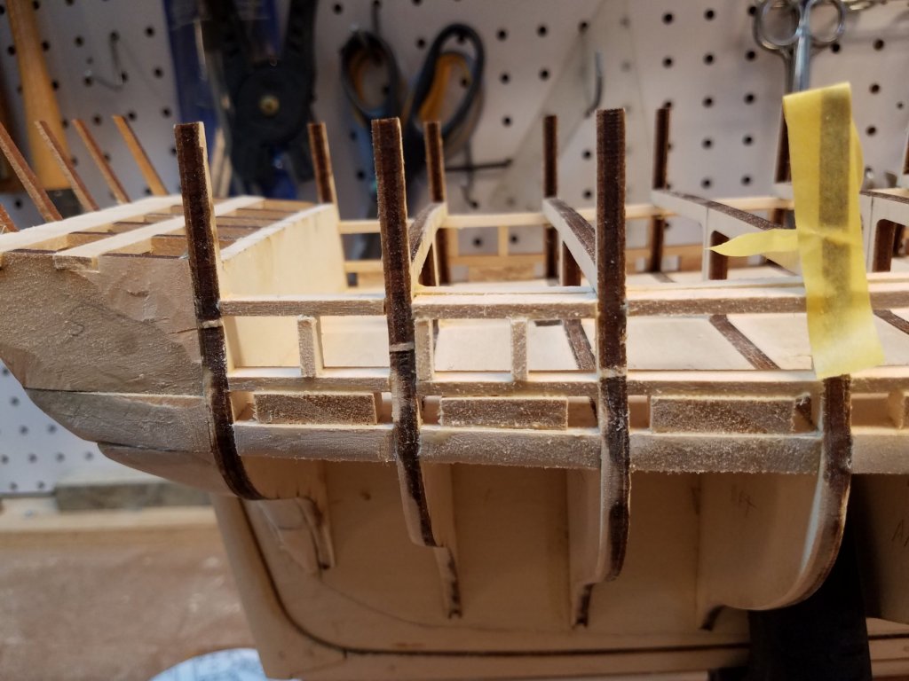
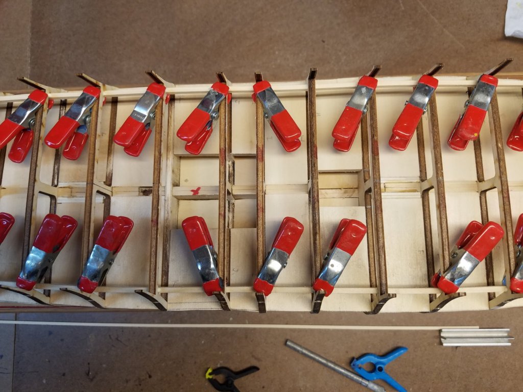
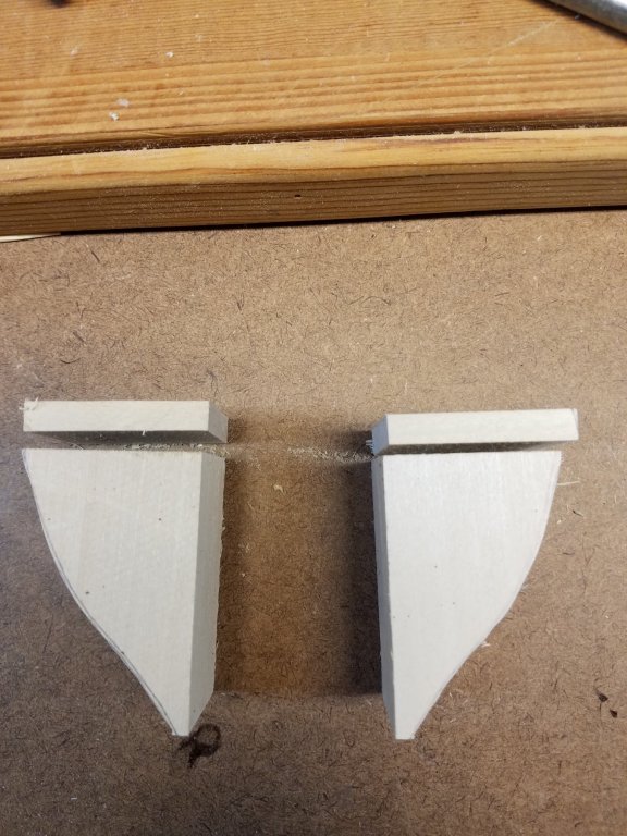
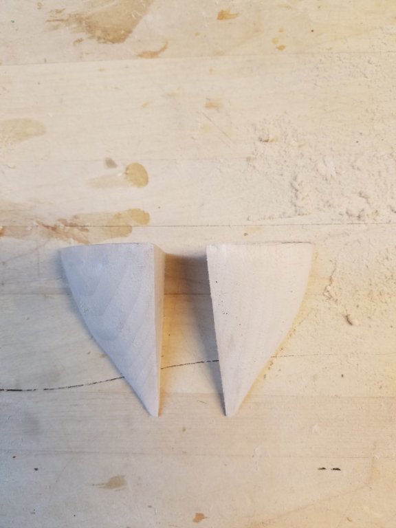
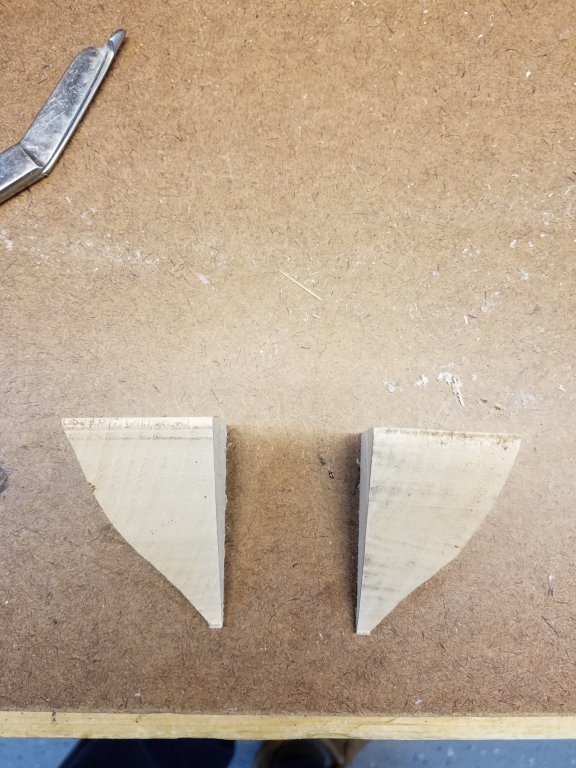
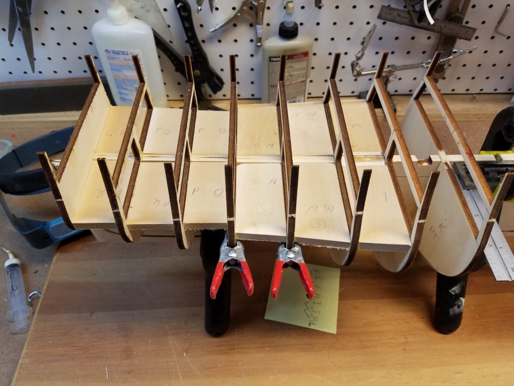
Posting Continued So the incident with the struts opening I'm concerned. but I need to continue on. I'll keep watching to see if they re-open. Hopefully the infusion of the glue helps solve it or at least stabilize it. For now at least. the gaps are all closed and have stayed that way for the last week+ post re-gluing. I decided the next part I would work on on is the gun deck gun ports. I figure that putting these in will help strengthening the thin upper parts of the bulkheads before I start cutting out deck beams to model the gun deck. First, I made some jigs I cut a piece of stock to 10mm x 14mm. This is the inside dimensions of the gun ports. So as I frame the gunports... this block should fir in snugly and tat will ensure they are framed square and the proper and identical size. Now I cut these into 2 lengths. Each piece is longer than the width of the ship. This lest me frame the mirror gun ports on each side of the ship. The Next two pieces are spaces. they are narrow enough to fit between the bulkheads. and they are 6 mm high So .... to make a gunport 1) place the spacer on the strut. 2) Cut out 4 pieces to be the sill and header of the gun port. (they should all be the same length. the distance between the two bulkheads Note these need to be 3MM thick( hight) 3) Glue in the sill by placing it on the spacer. -From the plans, the top of the sill needs to be 9mm off the high of the gun deck -remember my struts are at the same height as the bottom support on the bulkheads. -And from the plan. The bottom support of the bulkheads are at height of the gun deck Sooo The spacer = 6mm, the sill's 3mm 6+3= 9mm. (higher math :-) ) The top of the sill should be at the right height. 4) Repeat process between the same bulkheads but on the opposite side. 5) Now take the two long gun port jigs and place them on the sills. Make sure they are facing the right way up. 6) You can now glue in the header piece on both sides by placing them on top of the gun port jig. 7) Give the glue a 1/2 to set. Then carefully slide out the jigs.... You now have the gun ports sill and header, the proper and equal height off the deck and the header also equal and the right height above the sill. In two sessions in the workshop. got all 30 gun ports in. (hearer and sills only) Looking down the side, by eye , they look to have a good run. Now I still have to do the side pieces of the gunport. again using the jig., place it back on the sill and all the way across the hull cut and and glue the side pieces. Both port and starboard. So I was able to get the first 4 ports done. 2 on each side starting at the stern. Using this method. The sills , header and side pieces are all square and identically sized and proper height and symmetrical with its pier on the opposite side of the ship. In case you cant tell.... I've become kinda obsessive about making sure the gun ports look right :-) This is from my experience building the Friesland... ( a Dutch 2 decker 80 gun ship) Try aligning 13 guns per deck, om 3 decks , crossing 4 wales all with cambers... and make them look symmetrical. I digress. Also note... An added piece under the sill. There is not a lot of surface area at the ends where the sills are glued to the bulkheads. I was afraid that when working on the side pieces, they would be susceptible to breaking off. So with some scrap wood. I cut a bunch of filler pieces. 6mm high and same depth as the sill. Glued them underneath the sill. Now much stronger. To do all 30 gun ports took <2 hours . Now... If you've lasted this long and are still reading this..... You spent too much time here and should be in your own shop working on your own models :-) Just kidding! Final thought/ question before I end this post. When looking at the ME planes, the gun-ports are NOT evenly spaced across the length of the hull. Some have 25mm between gun ports . others are 30, 32, 28... However, when looking at the AOS side view.. They are all consistency spaced. So which is right? Did you other Connie builder experience this and what did you do??? Need to figure this out before I do any more work on mine. Till next post. K


-
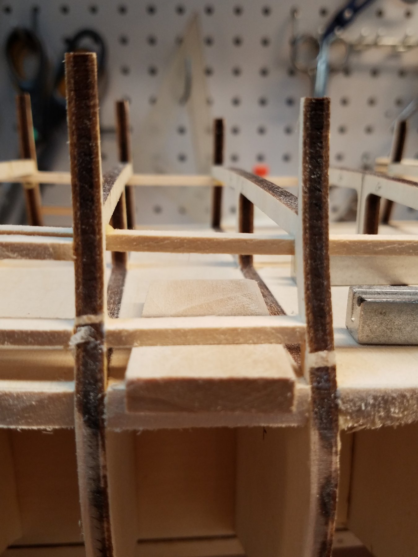
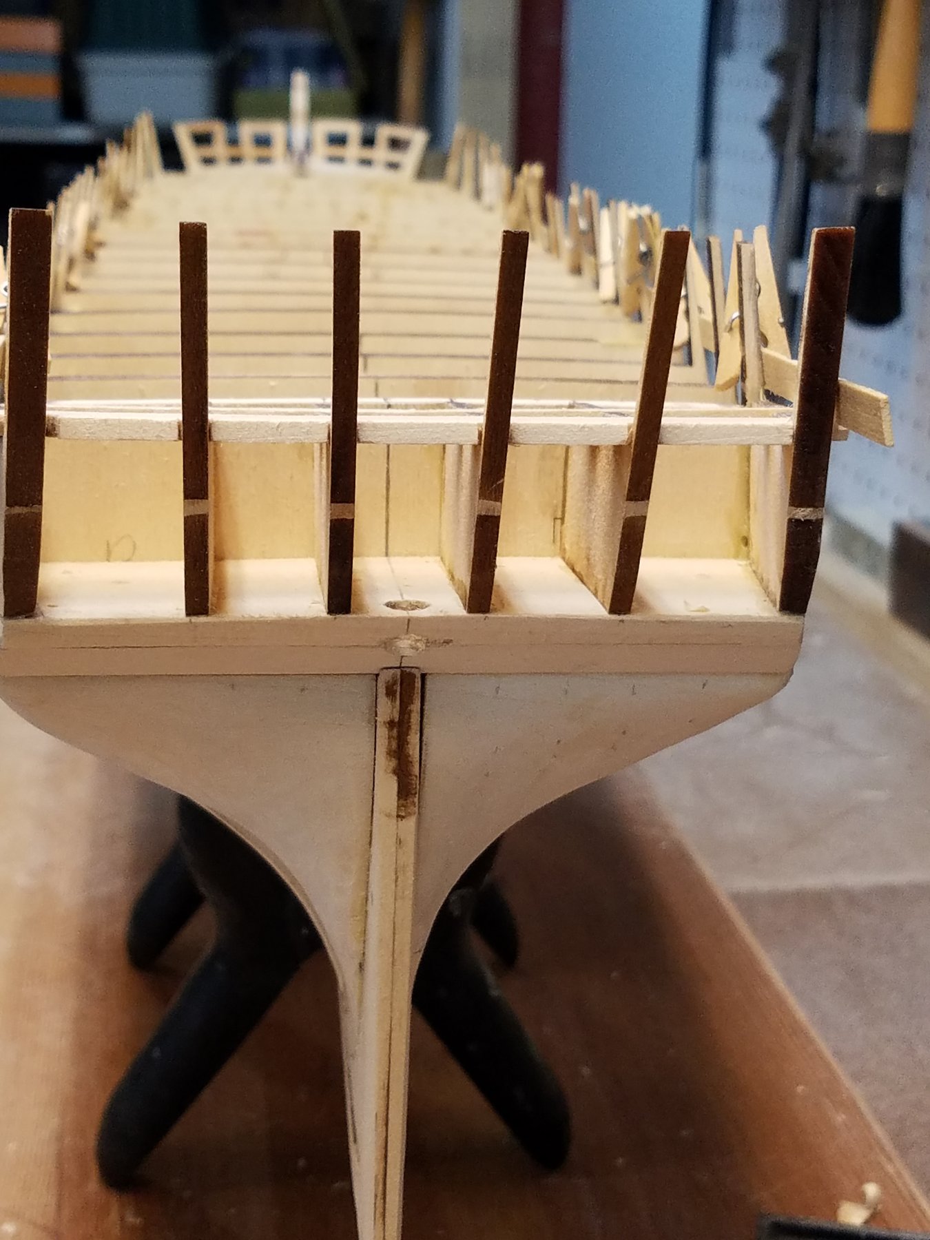
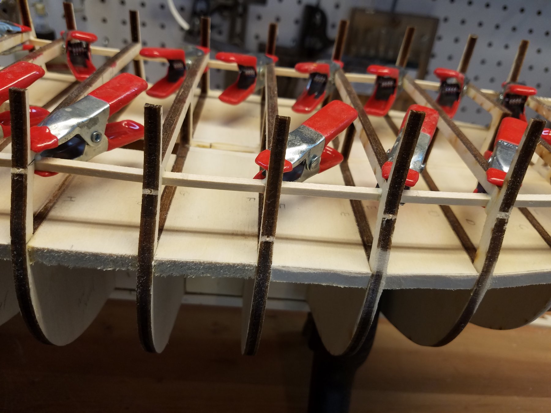
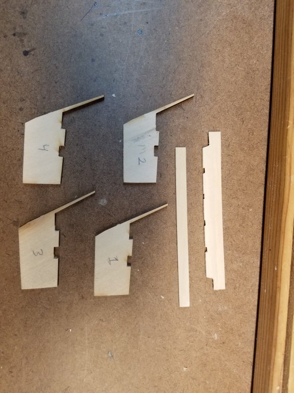
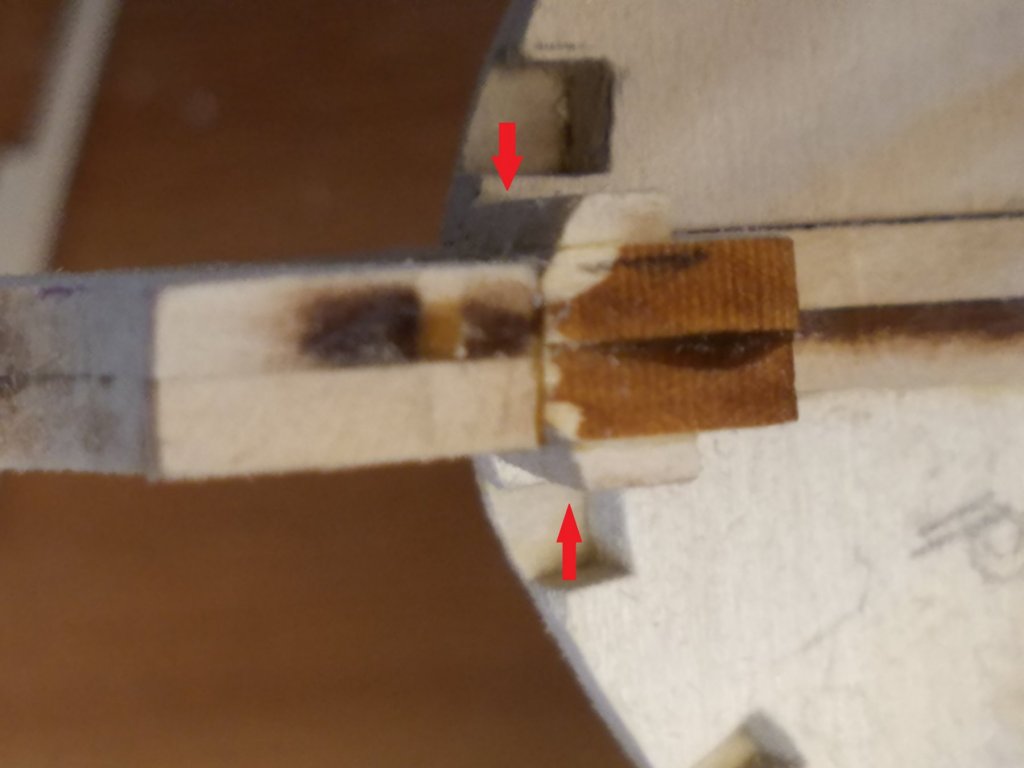
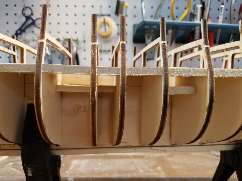
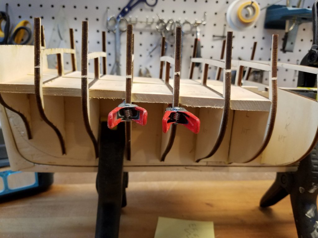
Thanks for the likes. And the Comments. I'm just glad people are taking an interest in my build :-) Have spent some more time in the workshop. Progress on the stern continues. I did decide to go with the 5 window stern. First step was to update my template with the positions of the stern pieces to match the proper position for 5 windows. Did this by comparing it to the scaled up stern plans from AOS With template in hand... Prepped the stern pieces. I made a Slight modification from the plans. I made the stern crosspiece wider, and then notched in where the stern pieces need to fit. This will help hold them in proper position when gluing in. gluing them in And checking with the template Was Progressing along. Then I got a big scare. Went to work on the model one night. (This was after recent cold spell we had New England.) Remember those struts I put in between the bulkheads.... Look Close Six of the struts. 3 on each side pulled away from the bulkheads. Note these were glued in with wood glue that is as strong as the wood . And the struts had a nice snug fit between the bulkheads and the frame. There was really no way , no where for it to expand or move. My first fear was the frame was now warped and ruined. But after checking and checking. it dosesnt appear to be. I put a square against the frames. The ones with the spaces were off... but very very minor. < 1mm. Not enough to ruin the model. And they seemed to offset each other between port / starboard sides. Now the funny part is. A few days later.. I went t to do some work and they went back to normal...The spaces closed up. Over the next week, this cycles repeated with the space opening up, and then closing again. I am baffled. My one though was maybe the struts "shrunk" due to humidity or lack of in my shop. But the wood had been in the shop for more than a month and had time to acclimate before I used it. So that shouldn't be the cause. My next thought is that the temperature varies in my shop greatly. My workroom is in the basement in a semi finished room. When not in use.... the baseboard heat is turned off.. and the room temperature hovers in the mid 50's. When I'm going to work (mostly weekends) I put the heat on and it goes up to 65 degrees. Would 10-15 degree swing make basswood expand/contract that much??? Anyhow... While the space was there... I filled it in with more glue. For the last week or two, the space was gone. I have not seen it open back up again. I keep watching. I don't know what I can do at this point or if it will re-open. Any ideas???? Anyone?


-
Looking good Tom, We are pretty much in the same place in the build.
-
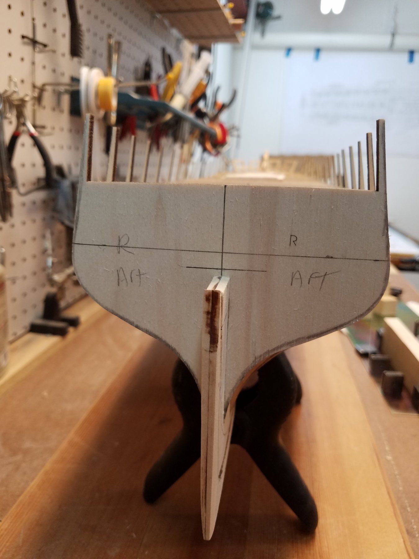
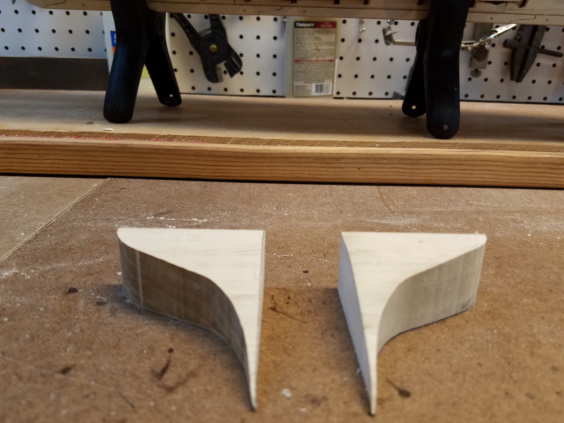
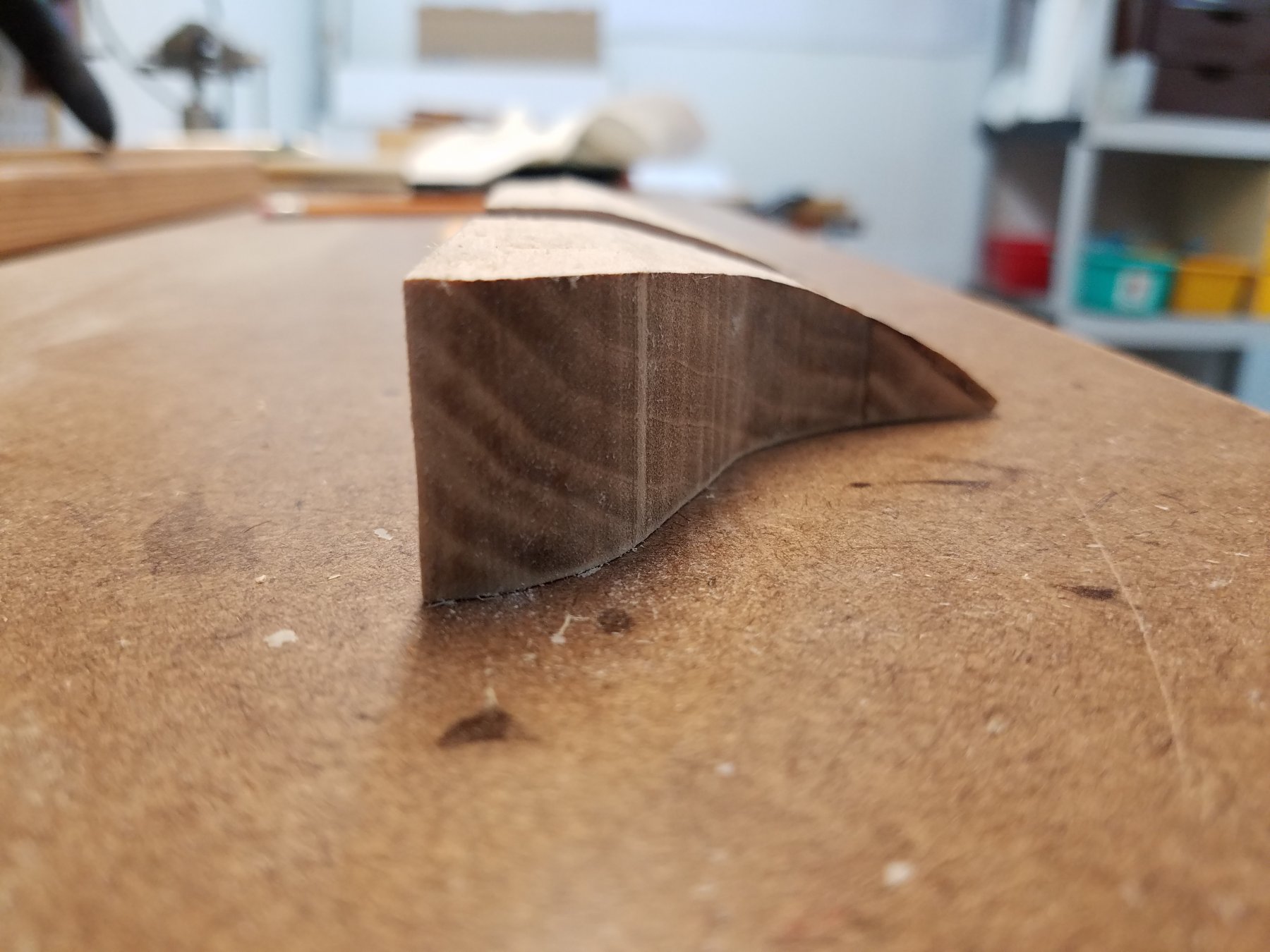
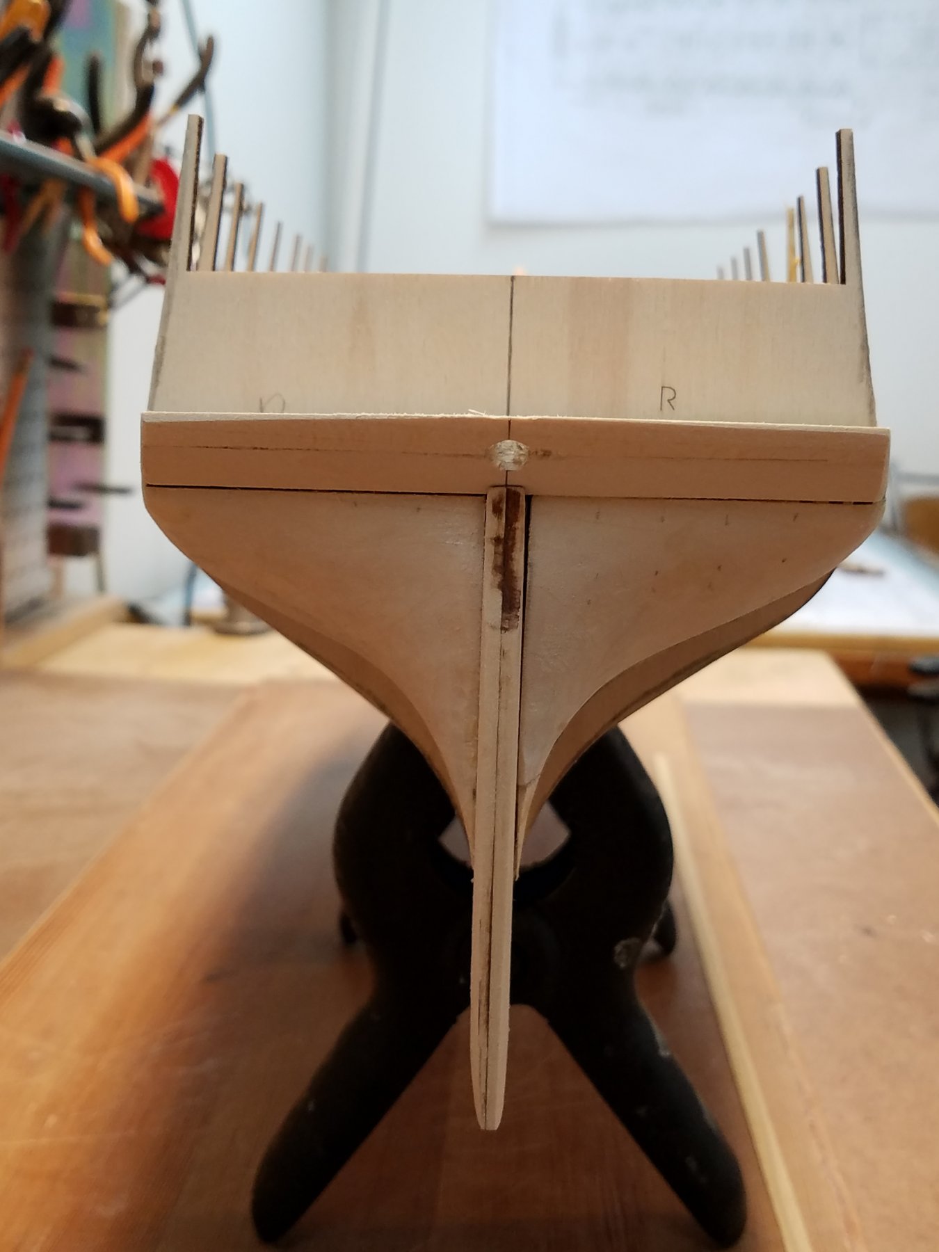
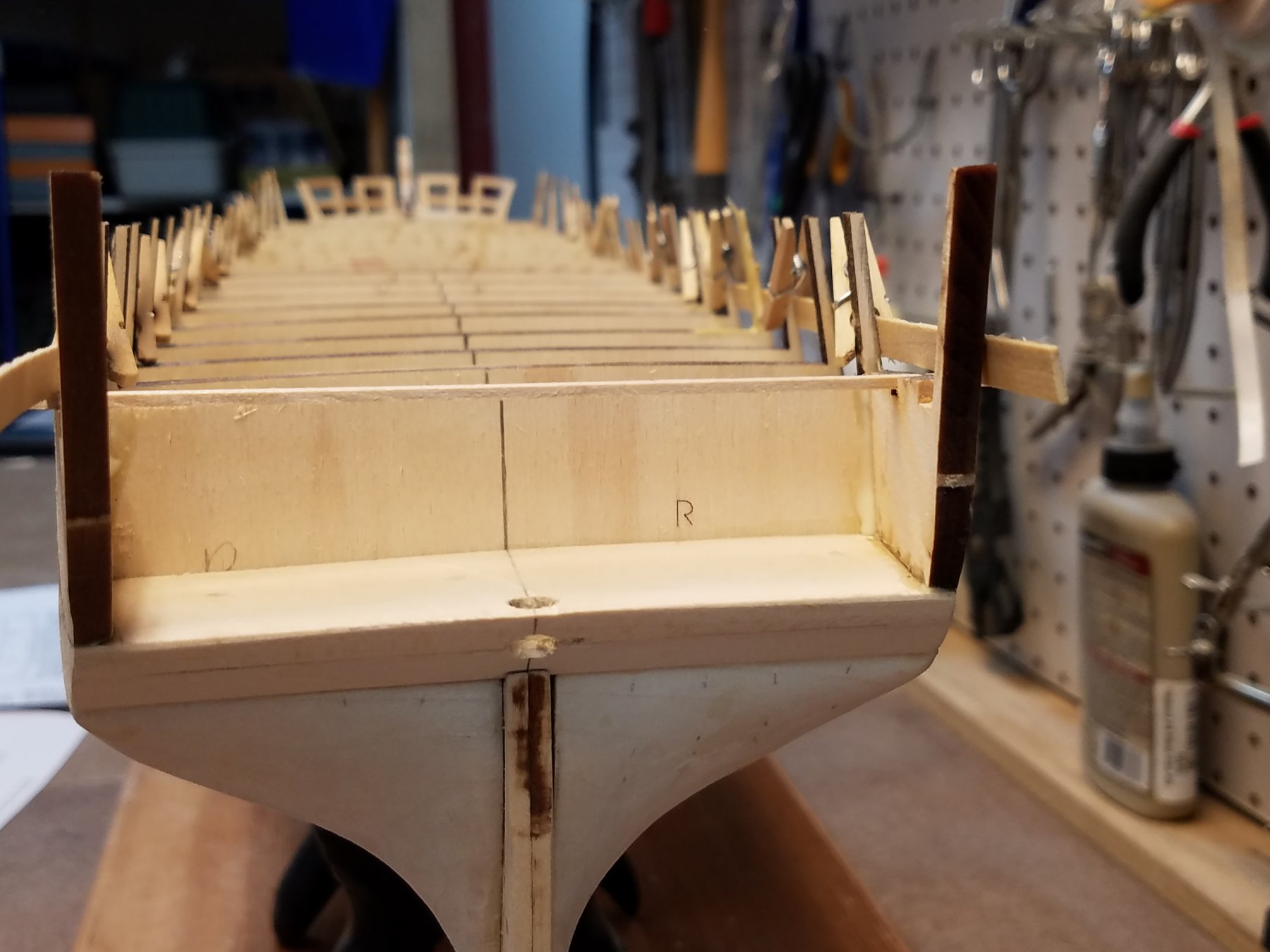
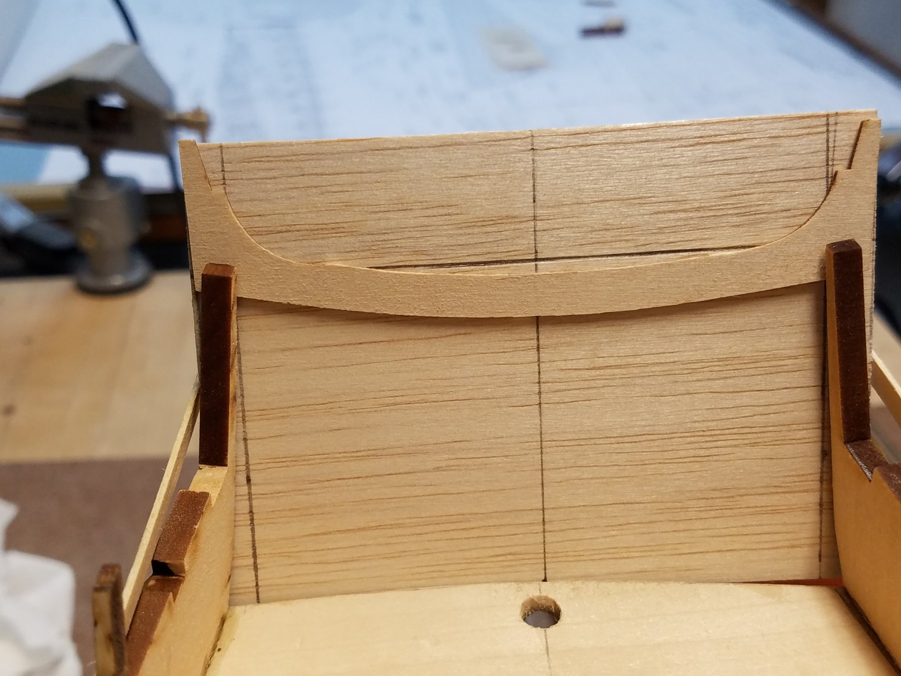
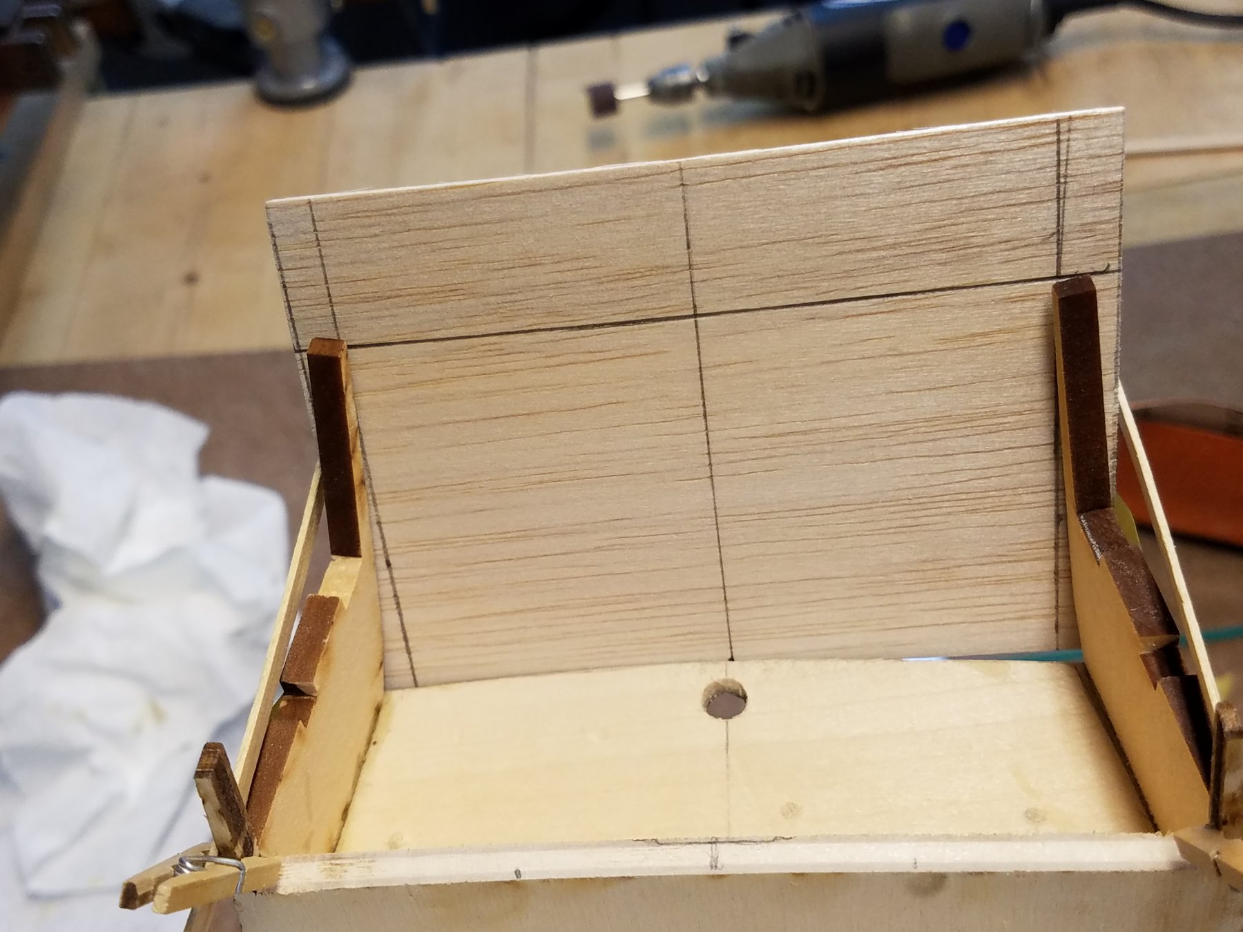
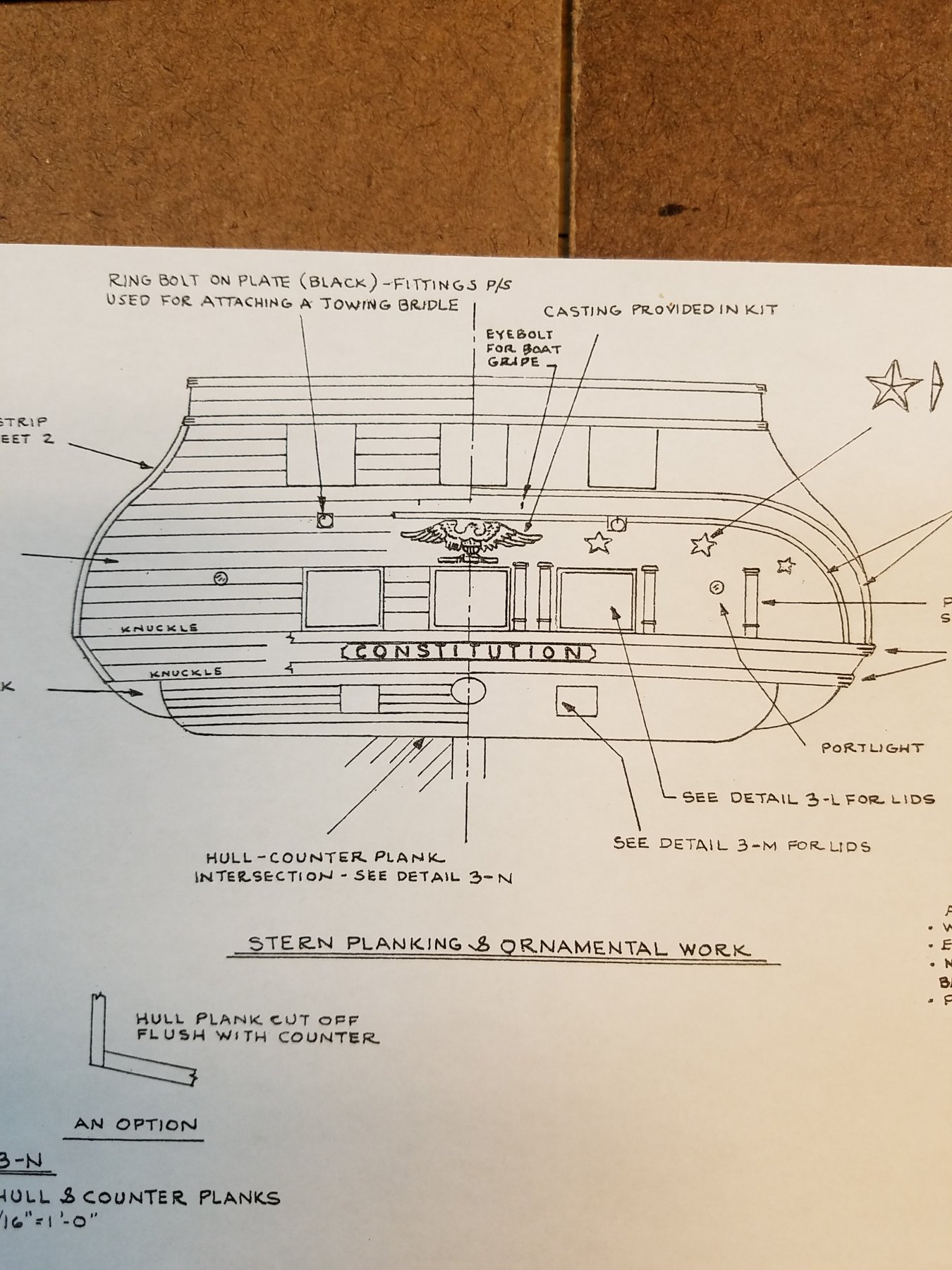
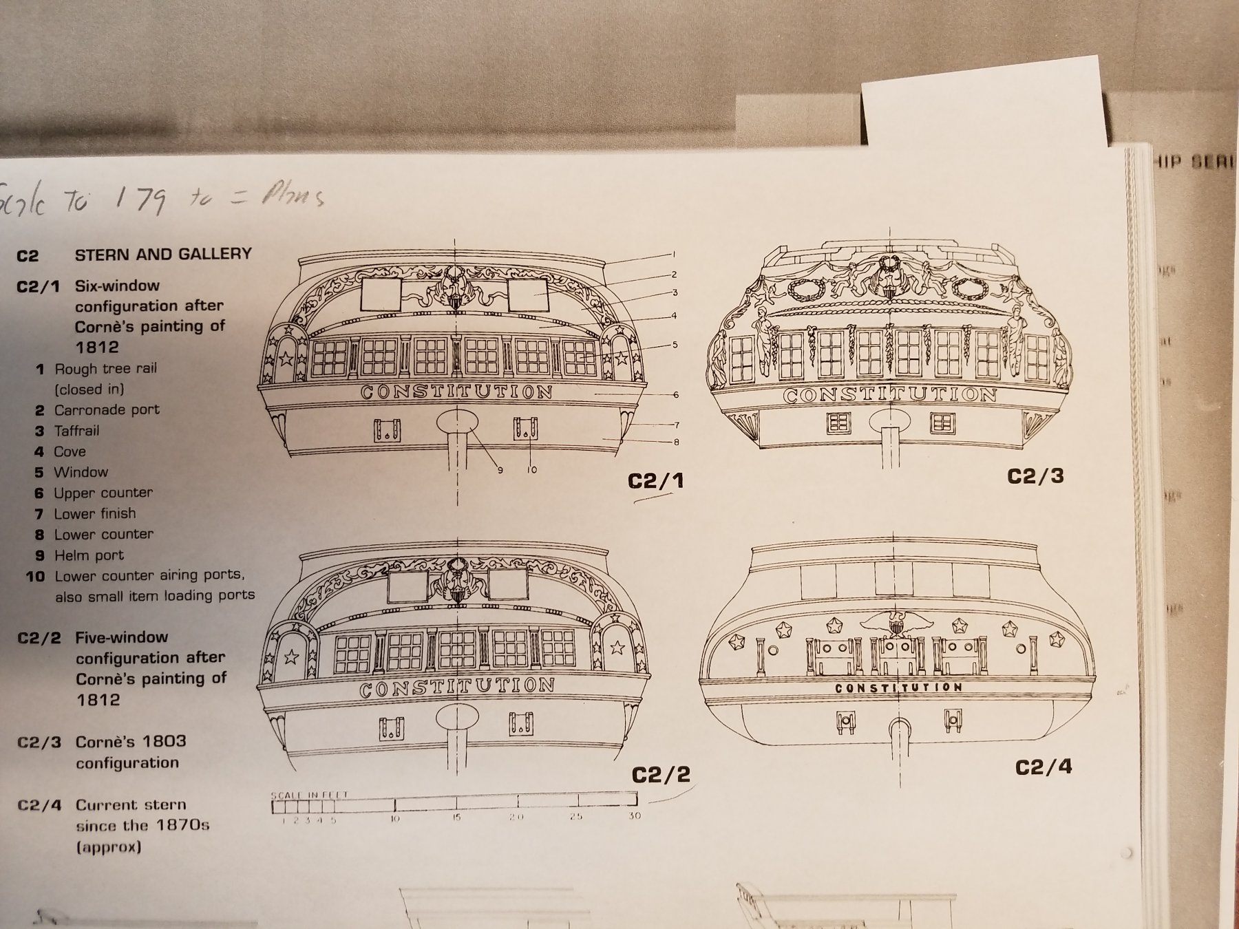
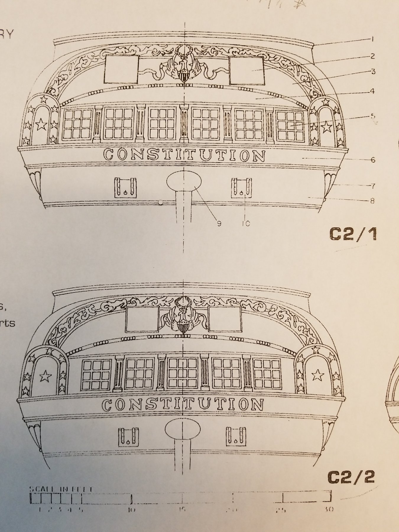
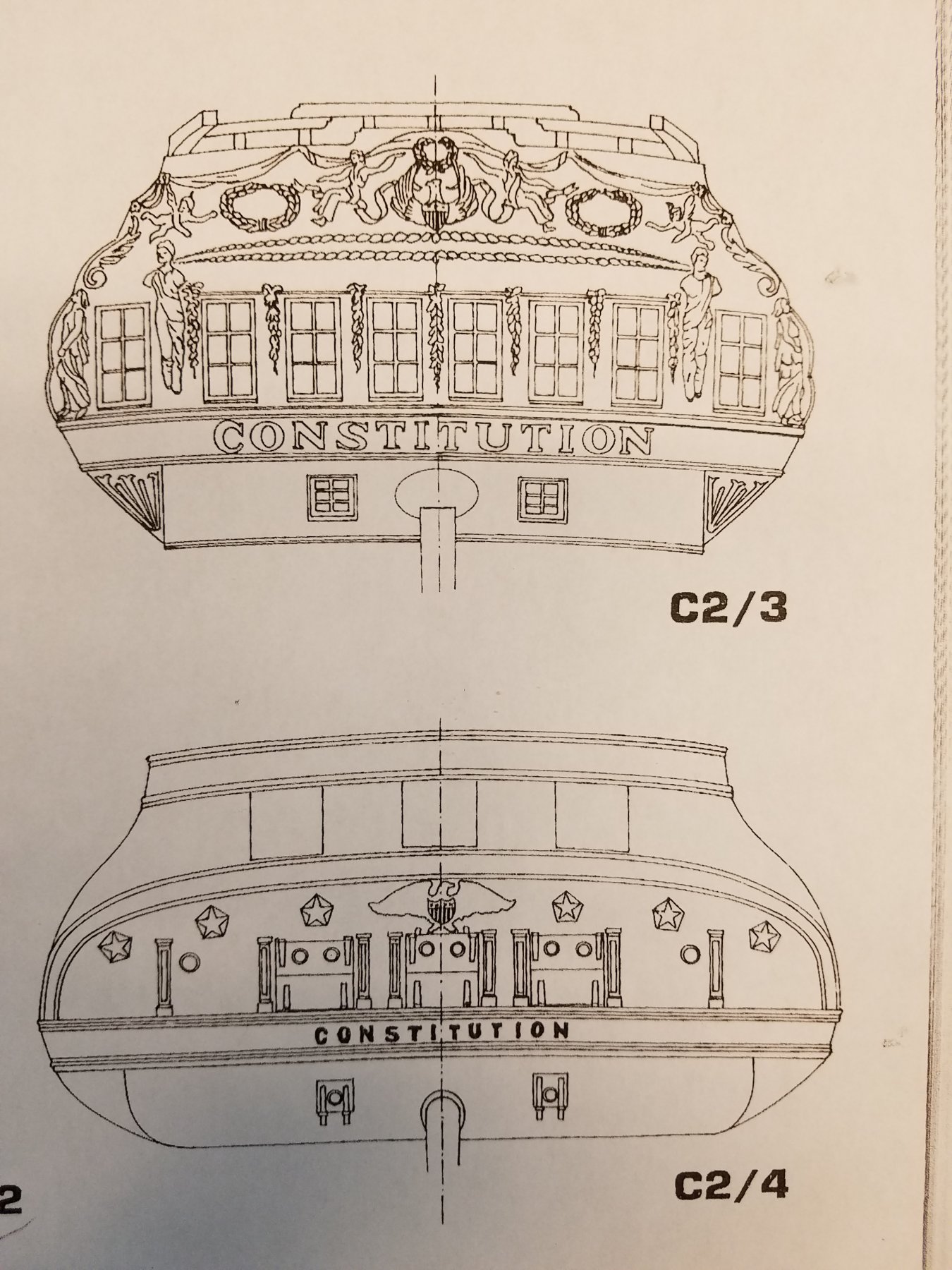
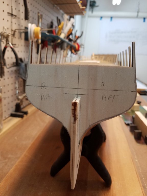
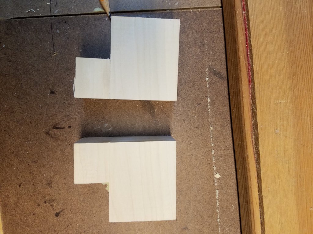
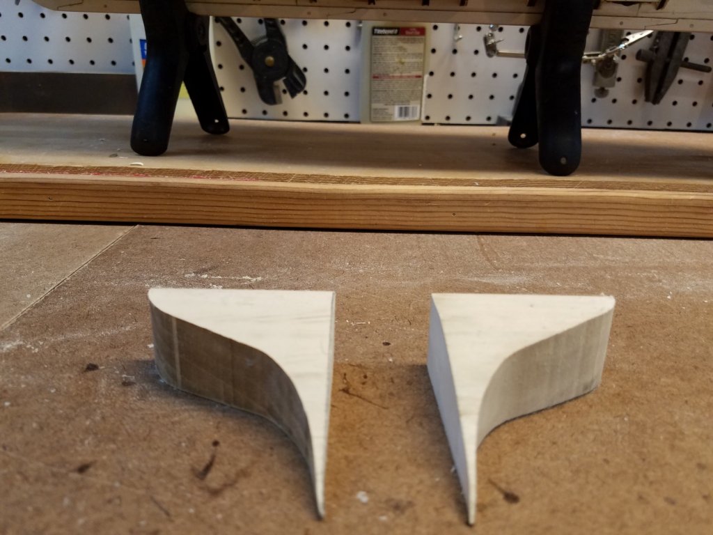
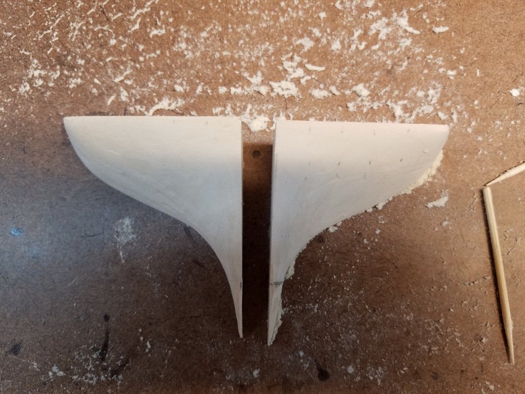
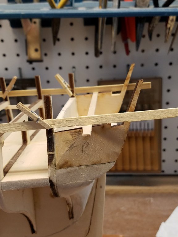
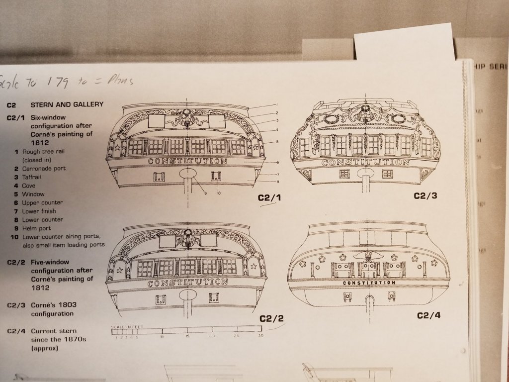
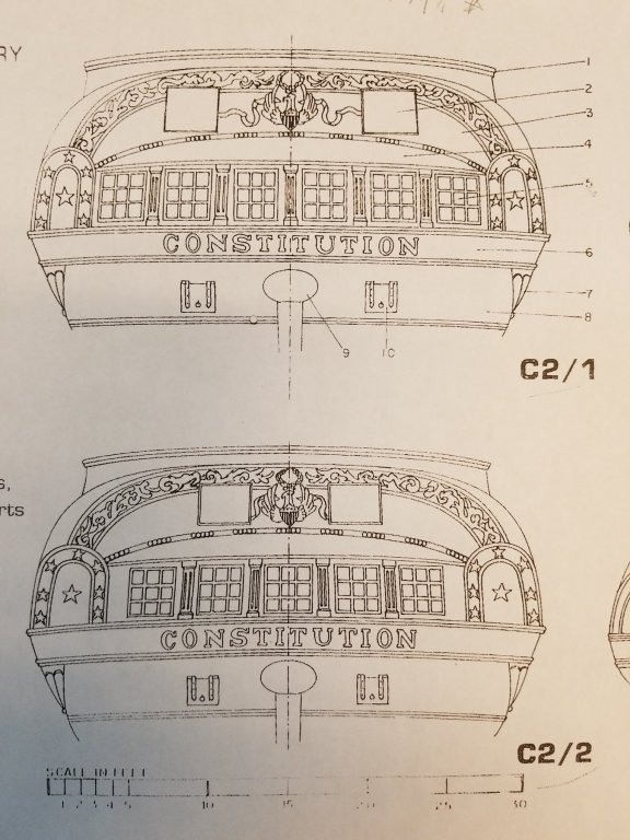
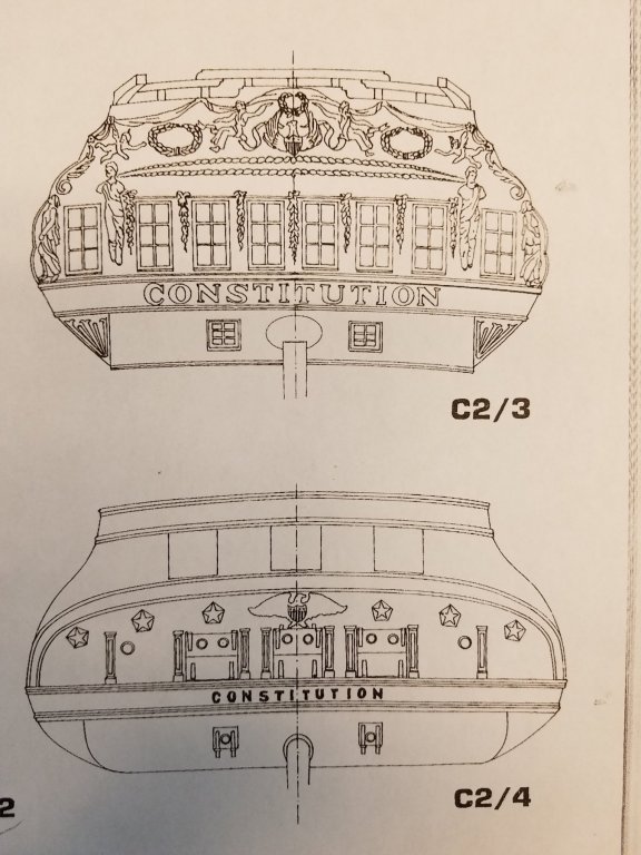
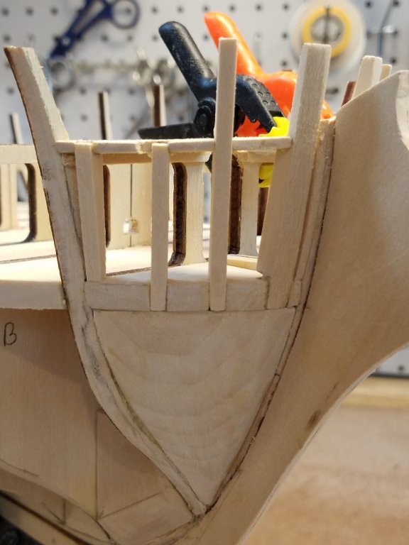
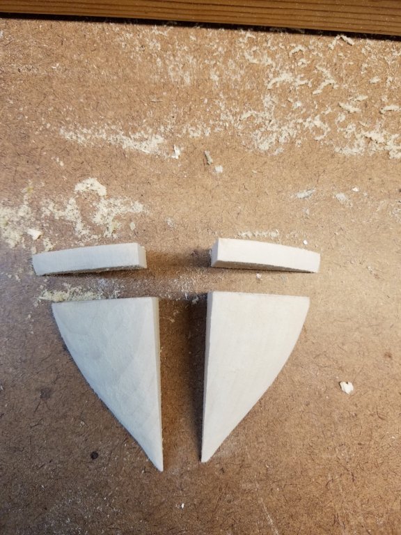
Thanks Usedtosail. Yes, I found the bow challenging. I'm glad how it came out. Now on to the stern. I figured it would be easier after working on the bow.. But I'm finding that its a real bear. I've spent hours and hours staring at the plans trying to figure out the stern. First I started on the filler pieces. Marked up the R bulkhead with some reference lines. G Glues some blocks together to be larger than the shape I needed. Rough cut them on bandsaw to the approximate shape Made lots of sawdust using a dremal tool and sanding drum and sand paper to get to the right shape The lower tips broke off. they get quite thin. I was able to glue them back on. But they are supper fragile unlit they are glued in place. Before I glue the filler, started working on the counter block. The counter took me awhile. and several attempts. The main reason being I tried a different approach than the directions. What I was thinking was to make the counter in two slices instead of 1 thick piece. The lower slice was cut to a thickness that would make the top surface the same high as the gun deck. What I was trying to plan for was the quarter galleries. The floor of the galleries are at the same level as the gun deck. I was going to keep the counter block wide and extend it out to include the floor of the quarter gallery's. This would make positioning and building the galleries easier. However after a week of struggling with it, I gave up and went back to and following the instructions after all. Through all this...I failed to take any pictures..... So I'll jump ahead to pics with the counter block and the filler blocks installed If you look close at the counter block. You can still see that it is made up of two slices still. But the two pieces together still match the plans shape and size. Next I added the 2 outside frames of the stern. Actually I had to do this twice. Uggg Again, I spent hours looking at the plan, measuring and trying to figure out how to position these two properly. The difficulty being they cant inward, as well as its edge follows the angle of the bulwarks on frame R. And because of the angles, you need to bevel the edges so that they sit flush. and of course both sides need to be symmetrical but mirror. Well after all the planning, I glued them in places... they looked good. so I walked away and let the glue set. Come back a few hours later to admire my work. All looks good. But then for kicks...I take out the stern rail piece that lazer cut. This will sit on top of the stern bulwarks. My bulwarks were canted in way too much and were too narrow at the top. didn't match the top rail piece, Swear, swear some more. Then pry the pieces off without breaking them. (Thankfully the Glue was not yet completely cured yet and I got them off ) Soo Attempt # 2 I learned my lesson and made a template /jig to position the pieces properly. You can see in the pic the actual top-rail piece that the bulwarks need to align with. and a template with the positions indicated. With the template, the second gluing attempt was much easier and accurate. This time... much better. And some batons in place to make sure the run looks good as well. Now, I'll let those dry. And start planning for the next part. As this is a 1812ish version... I need to pick the stern so that I can adjust the other stern frames to account for the sternwindow configuration. The big question 3 or 5 or 6 windows. I made a copy of the plans, and then a copy of the AOS stern versions. Then after an hour playing with scale, I determined the AOS picture scaled to 179% will math the ME plans. Or close enough. So I printed the AOS versions to the same scale as the ME plan. C2/3 (1803 version) and c2/4 (current day) are both out of consideration. But I used C2/4 to size and compare the scale to the ME plans. At this point, I like and would be happy with either c2/1 or c2/2 they are basically the same except for the 1 extra window. I'll play around with adjusting the frames to see how I can make either of them work. Right now I'm leaning towards the 5 window version just because it makes the framing easier. I'll let you know what I decide in my next post. K


-
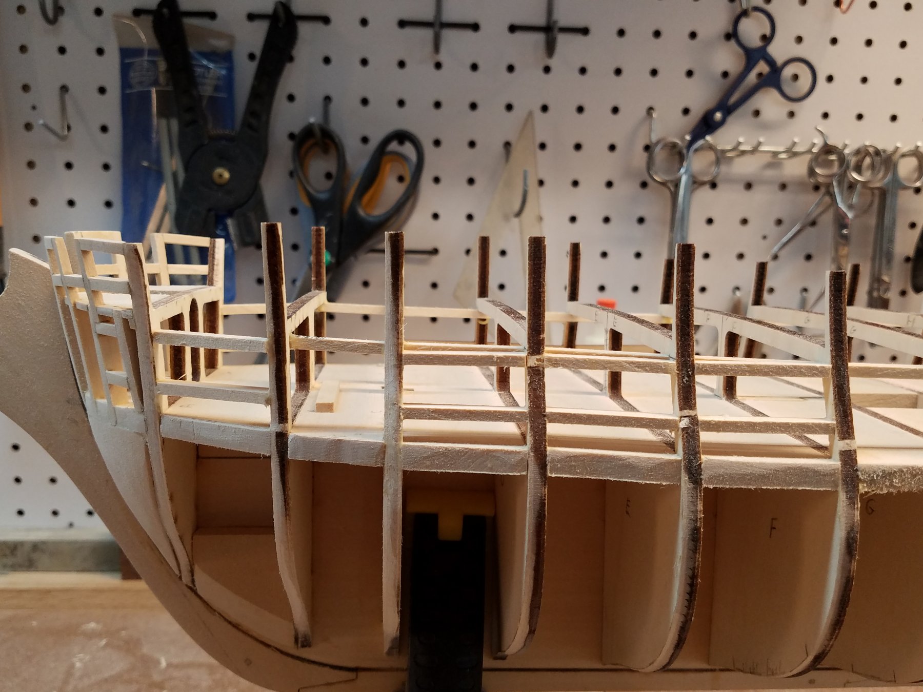
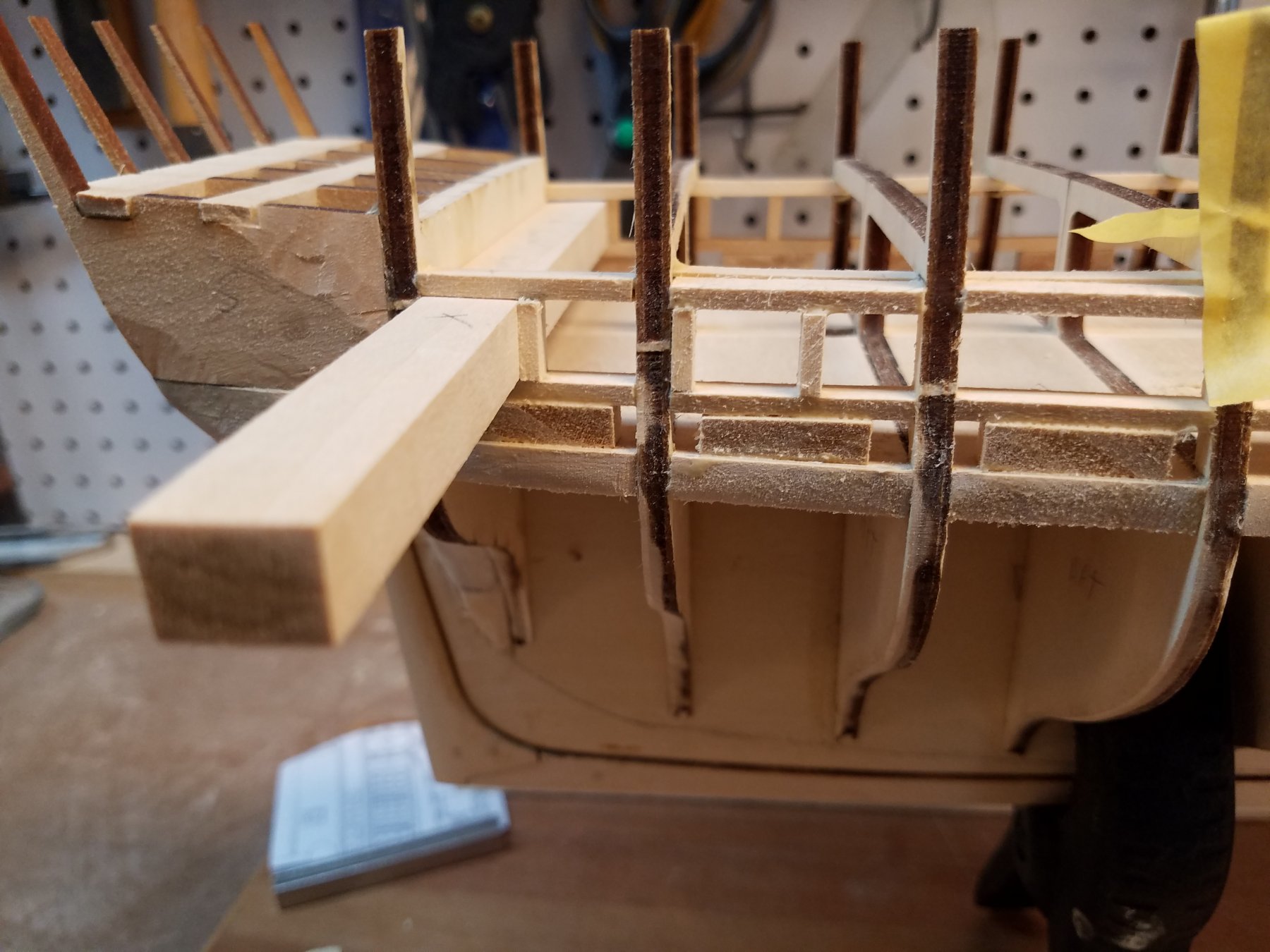
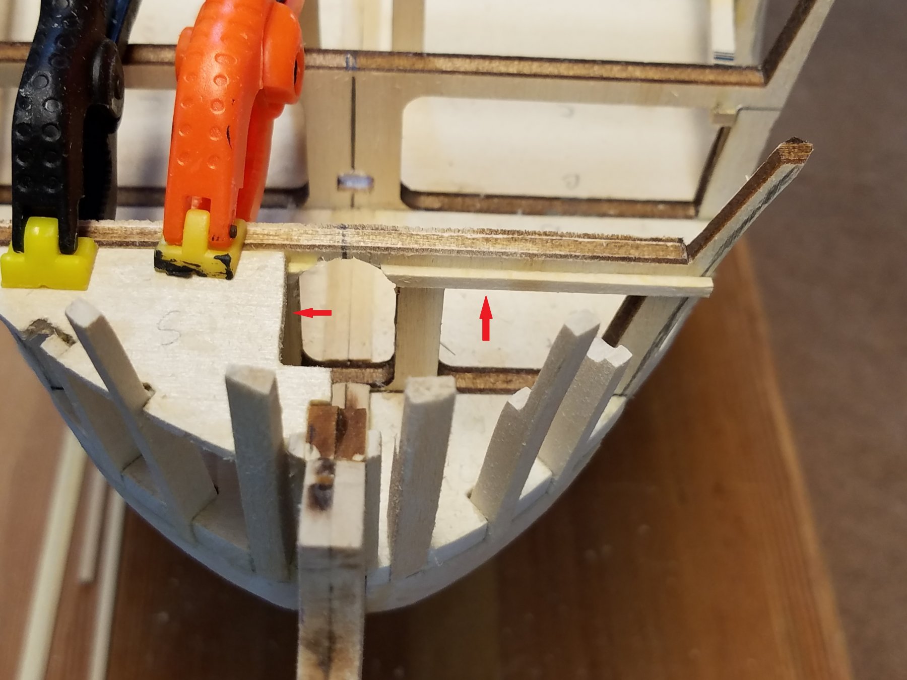
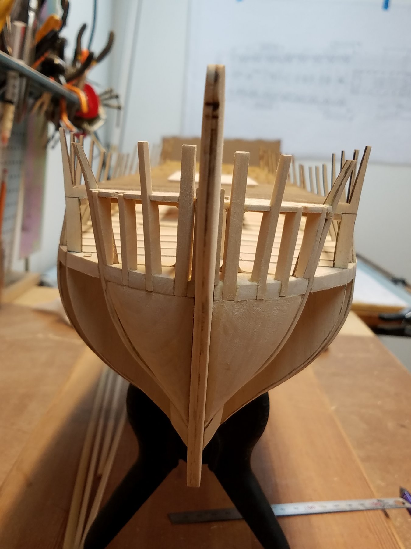
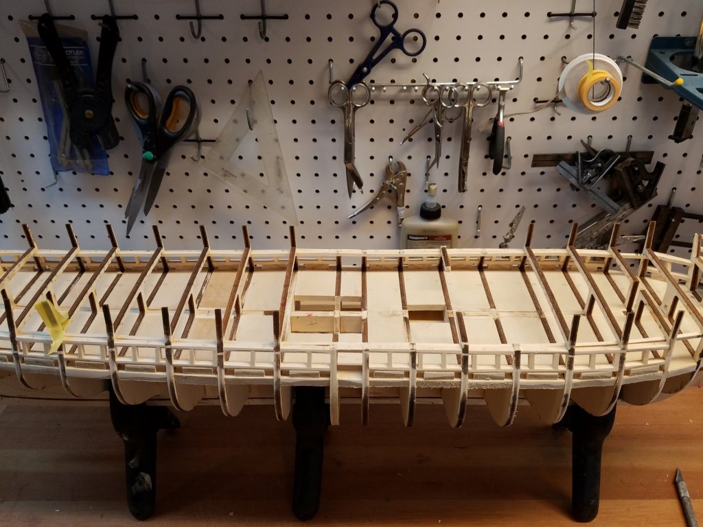
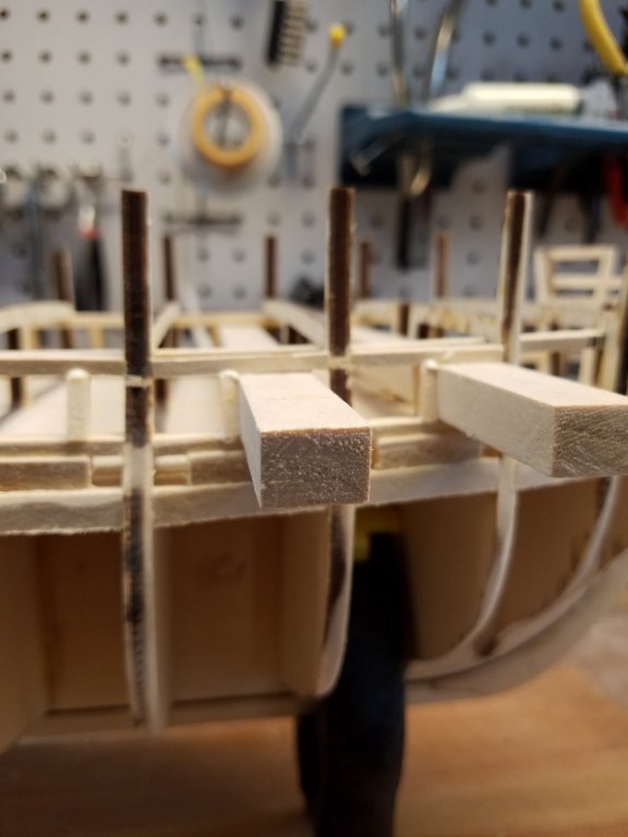
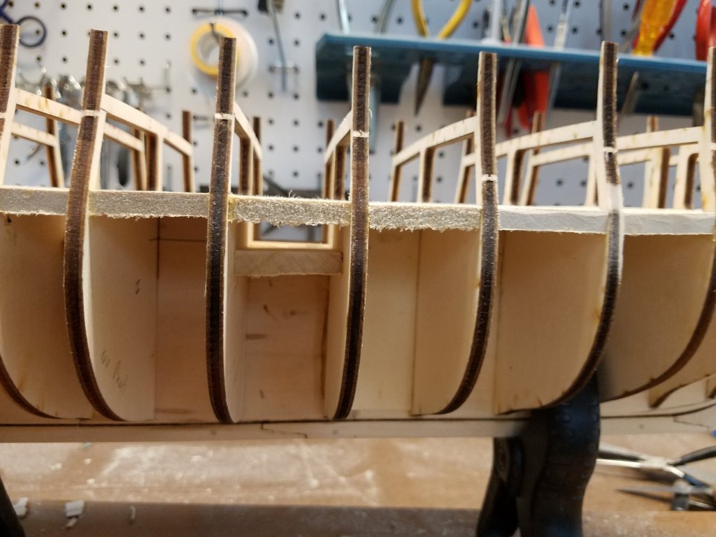
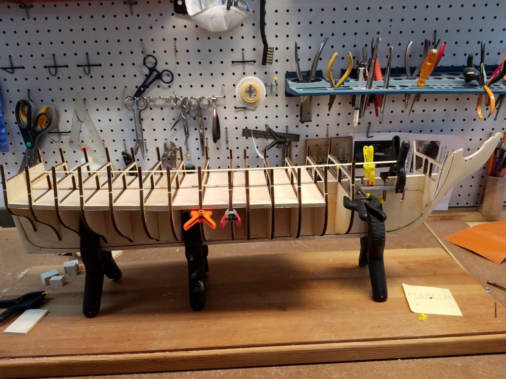
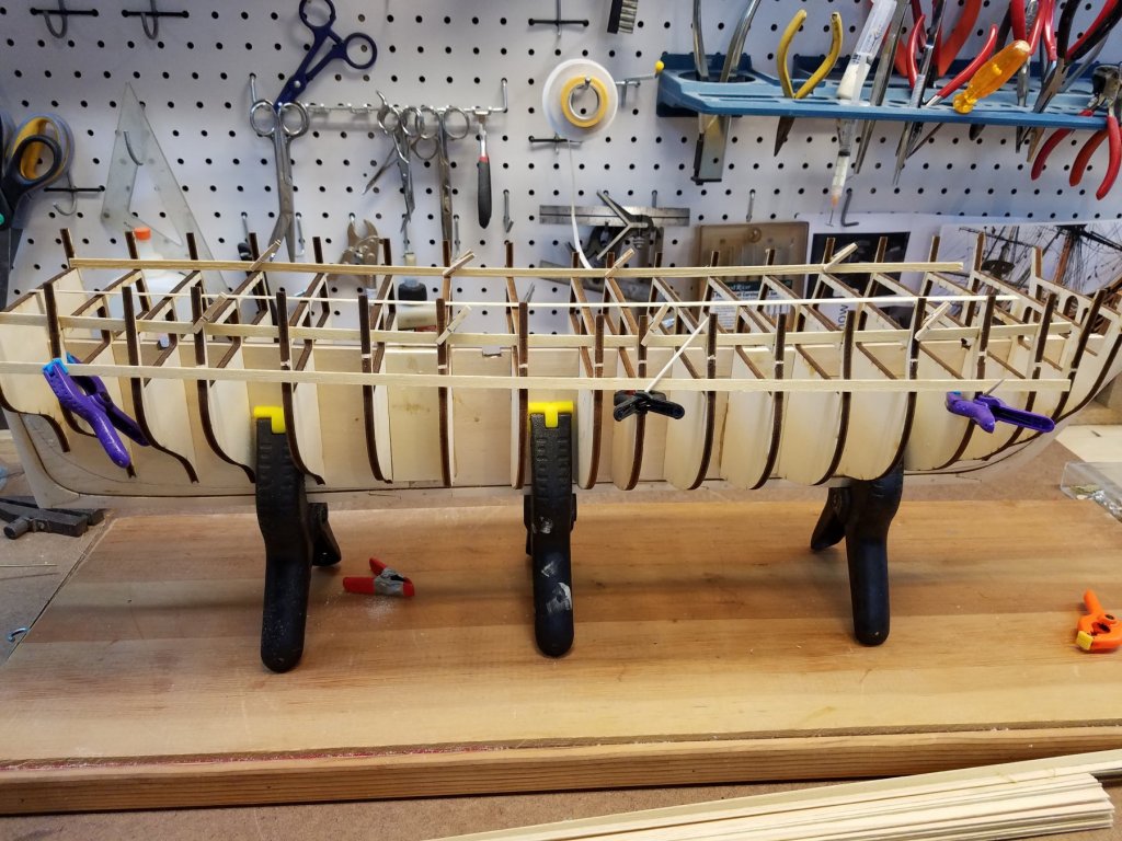
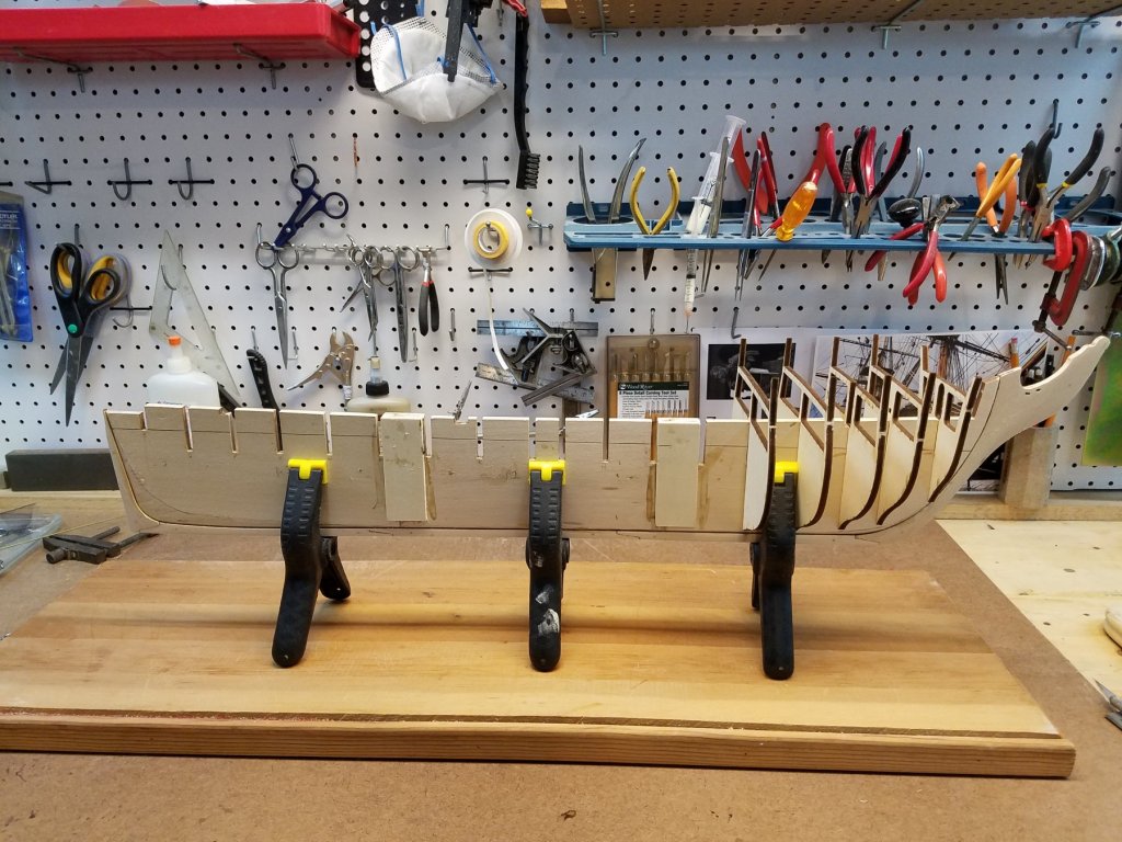
Next Update I added a stringer on the underside of the spar deck beams. Reason for this is that I will cut out several of the deck beams center support in order to detail the gun deck under the open waist The stringer will help make the beams less fragile. Second because some of the beams over the center grating area don't match the actual beam positions from the plans. And the grating will be left open. these beams need to be replaced/moved with beams in the proper location. The stringers will be used to support the beams. Moved on to the bow frame area Notches cut for the bow frame I added strips on either side of the stem just behind the bevel. This is to add a bit more surface area to plank against I added a strip of wood just under the deck beam on A. This will support the filler piece that supports the bow frames, Also, I made the filler piece bigger than the instructions show. I made it square against frame A and resting on the wood strip I added. With the ports framed in ... Both gun and spar deck Yes , I know starboard side is higher. There is enough wood there that I'll sand it down to be level. The ports are actually at the same height and all square even though they don't look it in the picture. Next up... the stern framing. but that's for my next post.


-
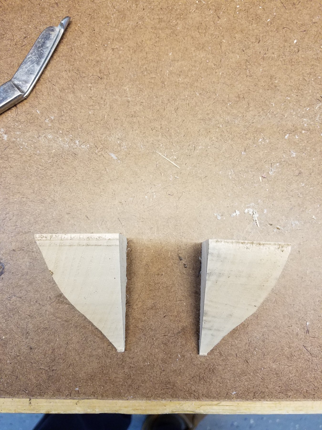
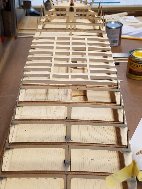
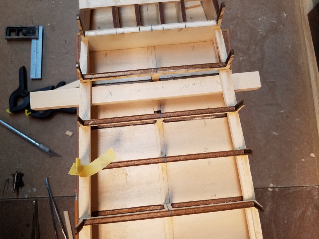
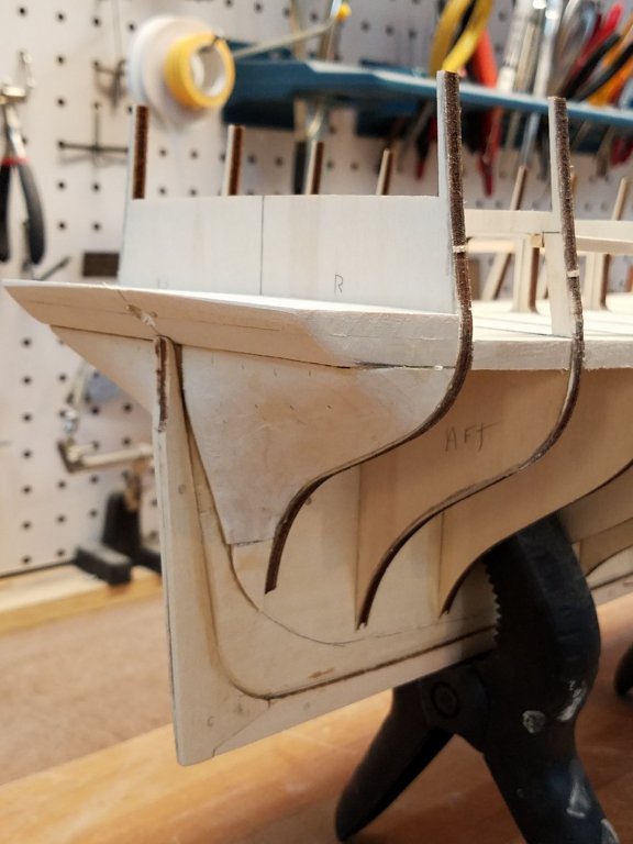
OK spent a lot more time cleaning up the bow filler blocks than I thought I'd need. They are as good as there going to get and ready to be glued on. Now, Due to poor planning, had to do the first surgery on the boat. As I'm going to have the open waist, I'll model whats visible underneath on the gun deck. That is a set of gratings. I'm going to cut up and use the kit gating that are not needed on the spar deck. I was just going to box around the gratings and put down on the deck. .... However..looking at the CD plans... There are several open stairways down to the Birthing deck. Well that means I need to add ladders and at least look like there is something below. Soo that means I need to cut holes in the false deck And then put a floor bellow that that the ladder will rest on II had to cut part of the bulkhead and part of the frame where the stairs will pass through. The aft stairs run parallel to the ship and go through one of the bulkheads. The forward stars run athwart ship and pass through the frame, Wow .. in the picture the run of the false deck looks wavy. But that's an illusion. (I've quadruple checked them :-) Ill paint the boxs later.


-
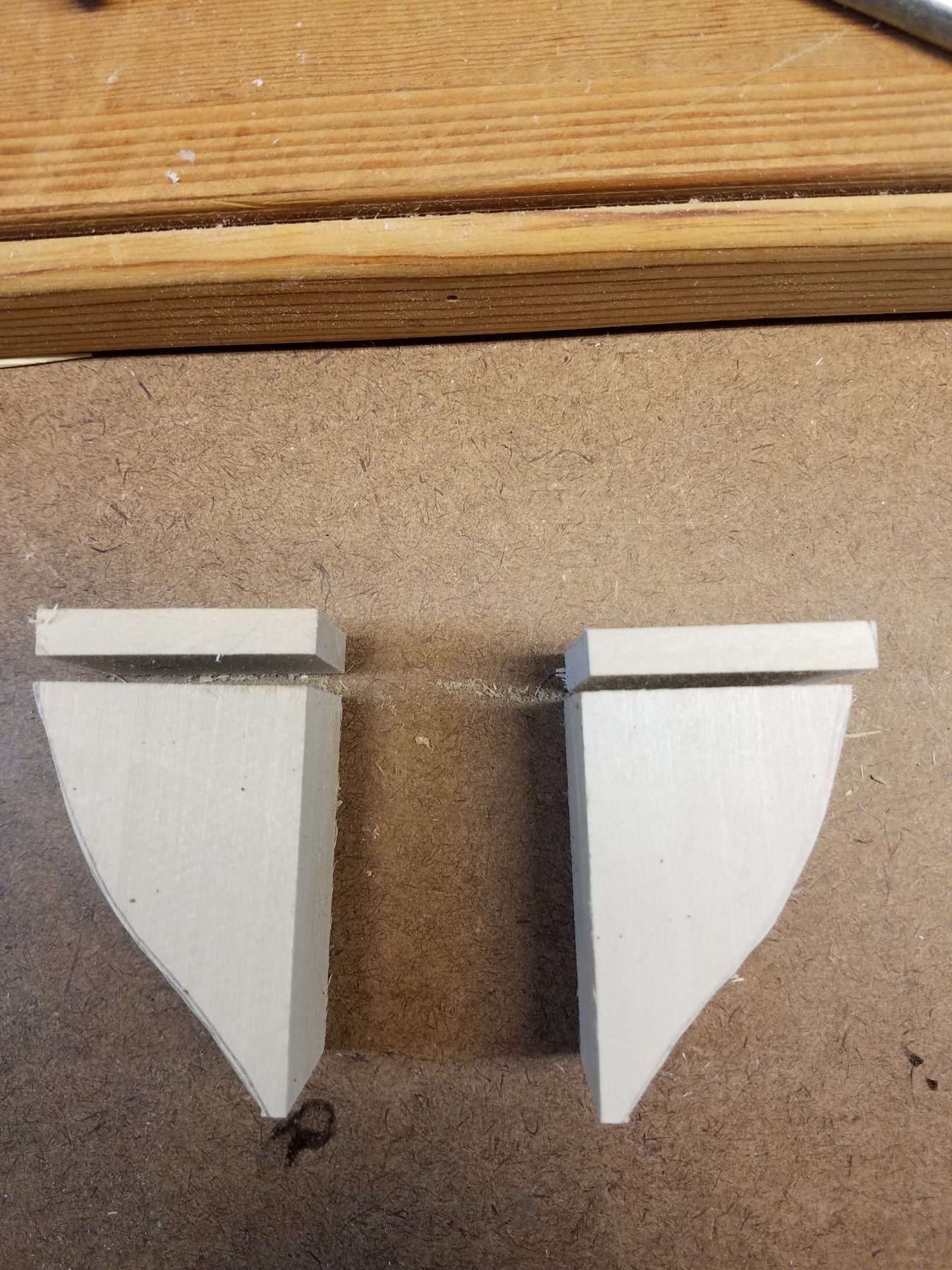
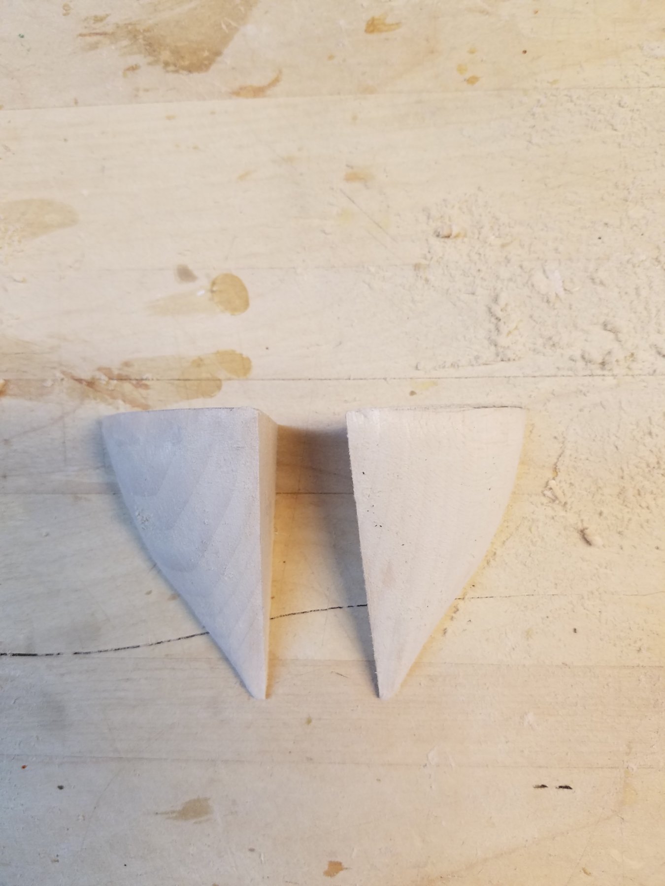
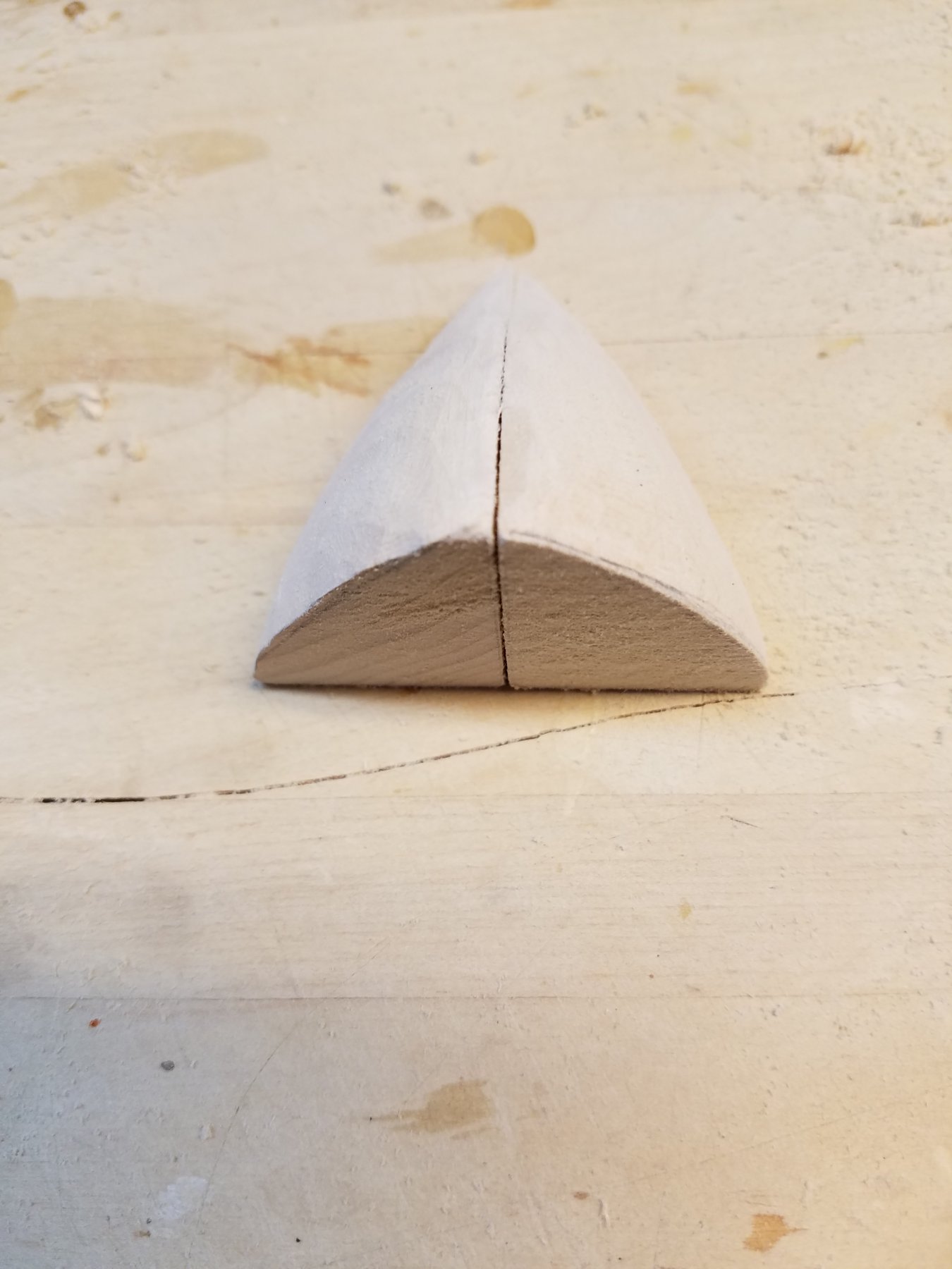
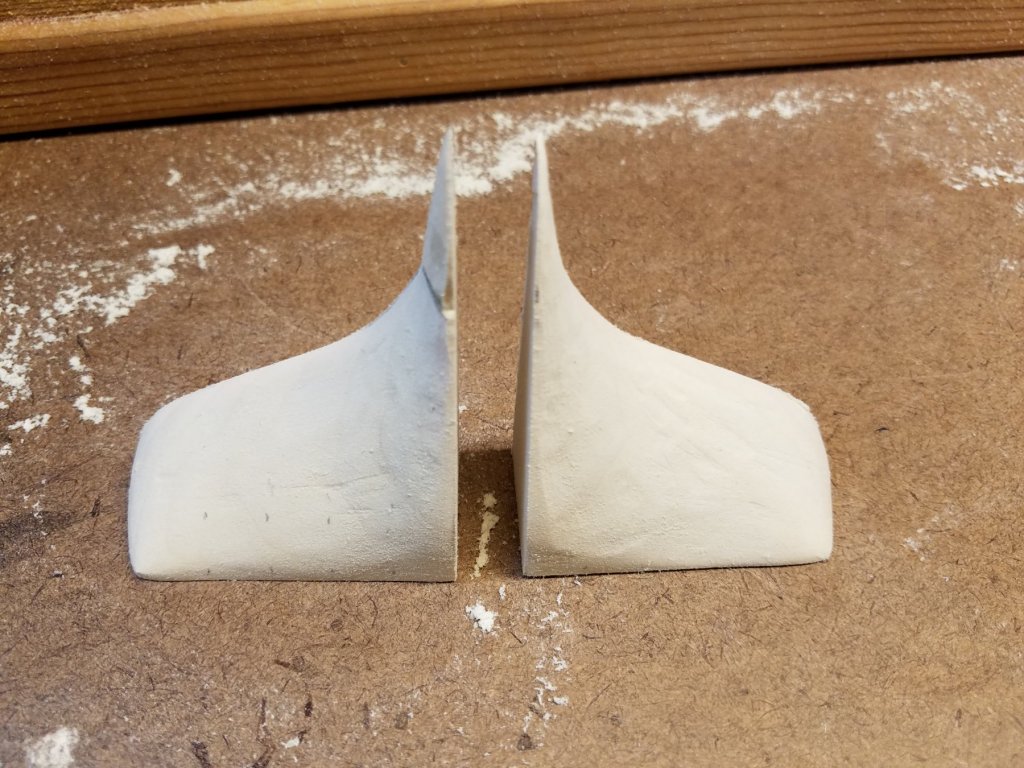
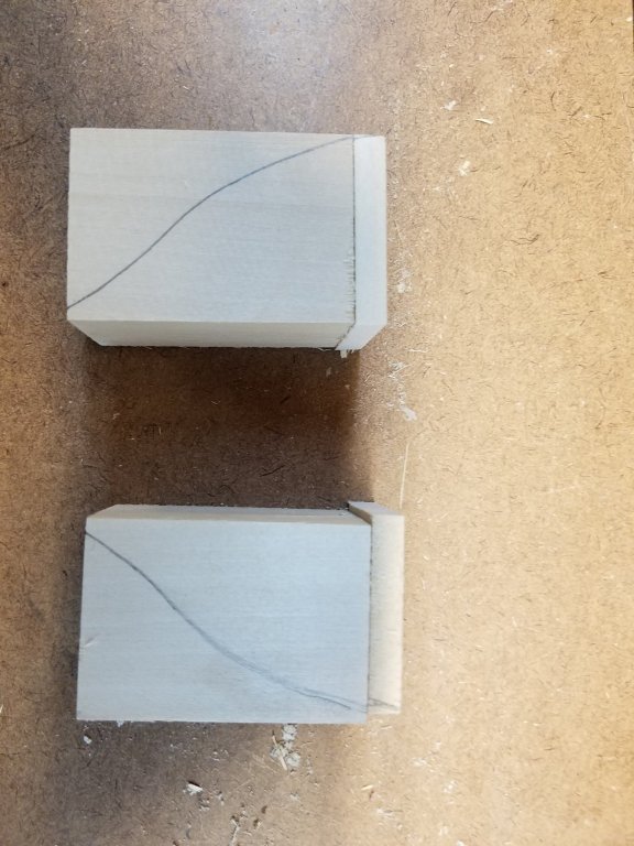
Time for progress update. Gluing the frames.. After adding the glue. used small squares on both sides to keep the bulkheads square to the keel. Kept them there till glue dried. which means this was a slow process. Only did 1 per day. As I went along, I also cut and fit/glued the struts for the prior bulkheads that was glued the day before. I measured the distance between the two bulkheads along the center line. Used that measurement to cut the width of the struts. That guaranteed the struts are same width on both sides (port/starboard) and the end set square against the frame. This ensured all the bulkheads were dead parallel and square. Also note, they were glued level with the top of the bulkhead gun deck beams. thus giving me a false deck. They took awhile to add but the Struts really add a lot of strength and rigidity to the whole structure. Frames don't flex or move at all. Also keeps the keel from warping. Starting to wok on the bow filler. Drew the pattern that faces against the bulkhead A on the blocks. Then cut out on a bandsaw Notice the two pieces of wood above the over the filler pieces. So the filler is supposed to have several notches cut into the top. I figured i can't cut them in until the pieces are shaped to fit first. But once shaped.. I'll have no way to hold the pieces square against a drill press or desk making it hard to accurately cut the notches. Soo, my thought is. Make the bow filler as the plan indicates.. but cut them 1/4 inch lower than the top of the gun deck. Then add these two 1/4 inch pieces on top. As those pieces are flat on top and bottom will be much easier to cut in the notches.... then just glue them on as the top part of the filler. Next I drew the pattern on the adjacent side ( that is against the keel) side and traced the rabbit onto the block. And then cut that out on band saw as well. The blocks was then very roughly in the proper shape in all three dimensions. Next I used a Dermal tool with sanding drum and sanded it to the final shape. Good news is they look very symmetrical. However, when I fit to the ship, it looks like too much curvature in the horizontal plane. I'll do a bit more sanding till I think it looks right. but they are getting close. Once done I'll tackle the top piece with the notches Thats all for now.


-
Wow. Great catch on the hole on the trailboard.
-
I'm pulling up a chair! Welcome to the Connie Club. I just started my build in Oct. There are several great builds of Connie currently going on. Check them out. Some great information, ideas out there!!!
-
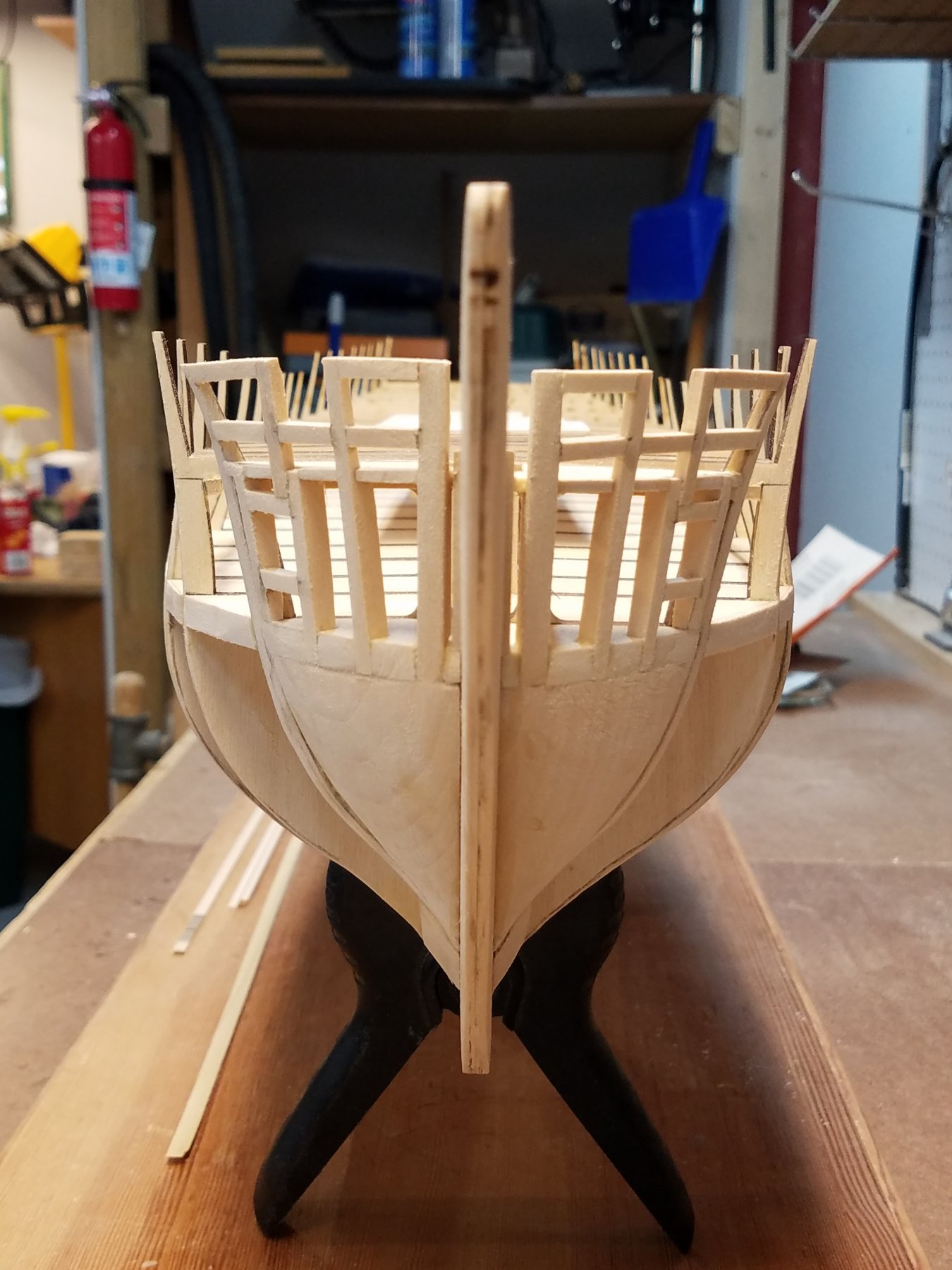
From another angle
-
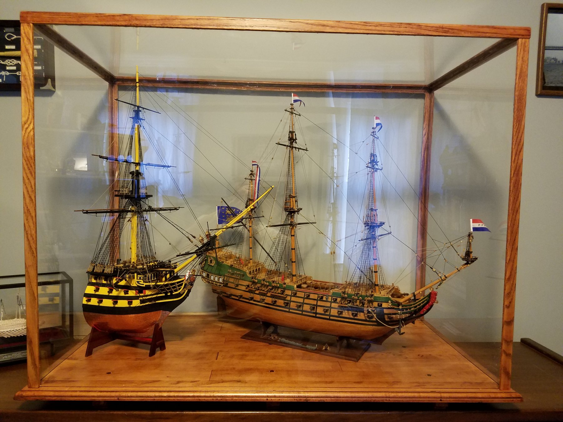
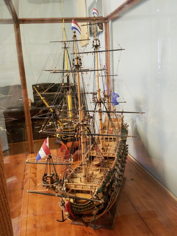
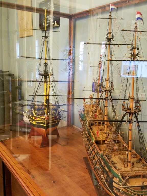
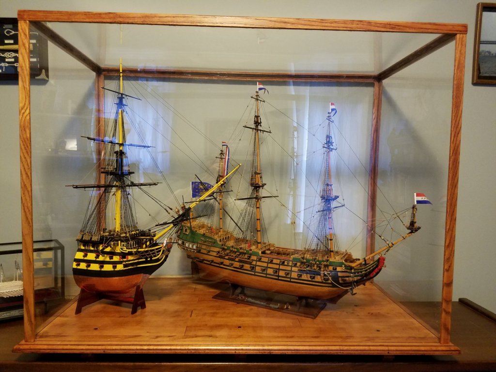
The Battle of Solebay: June 7th 1672 So..not related to my Connie build. My Prior builds are the "West Friesland" (a Dutch Ship) and the HMS Victory Bow section. Now I built a case sized for my Friesland. But haven't built one for Victory ..Yet. I 've been worried that the Victory will get dusty, or worse bumped and broken. So temporarily , I arranged them so they both fit into the Friesland case. Stood back... and realized..... I have a Diorama of the Battle of Solebay!! Yes, I know they are different scales Yes I know its a earlier Victory at Solobay .. not Nelson's But since they are both represented.... We have... The Battle of Solobay!
-
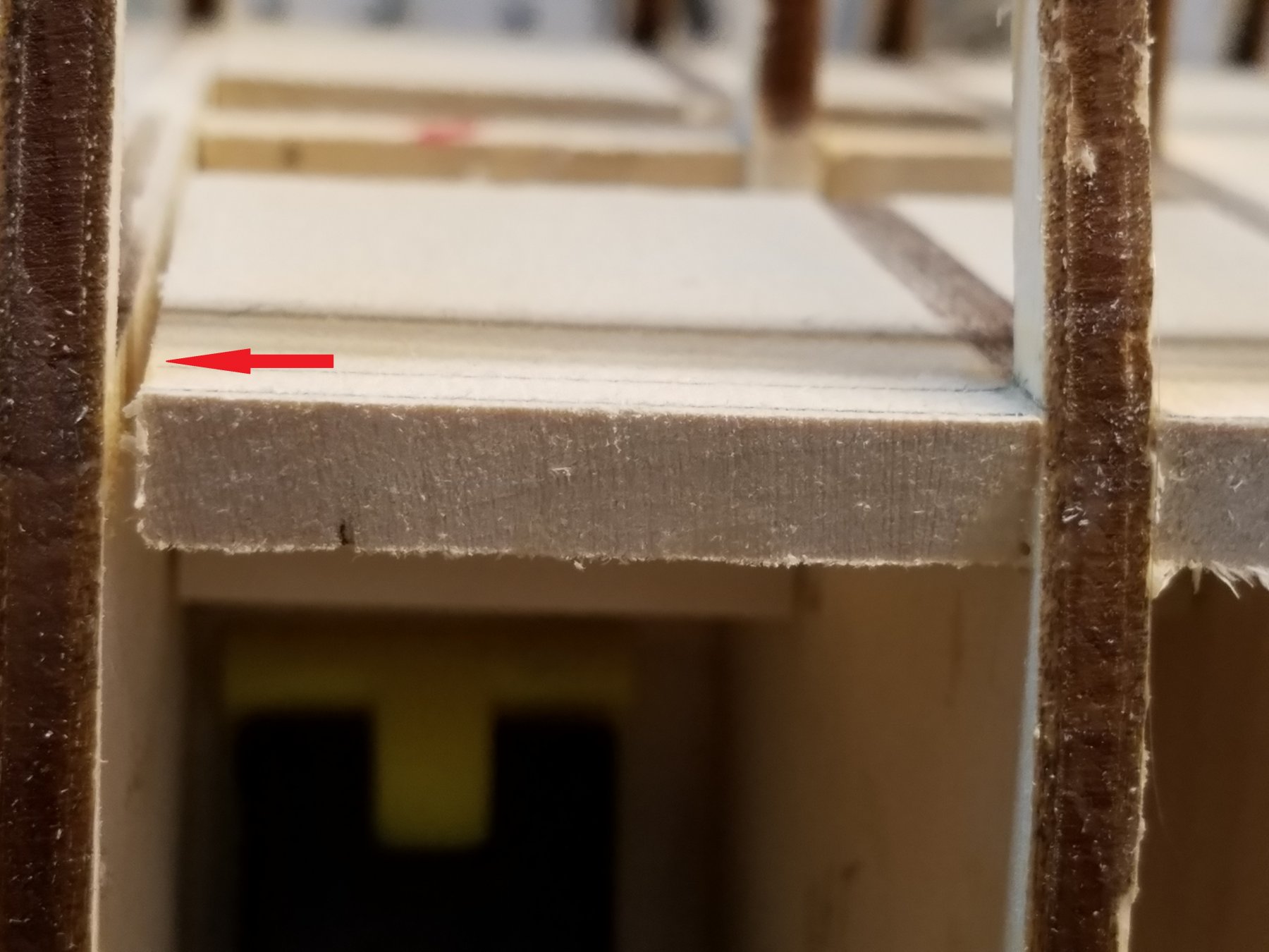
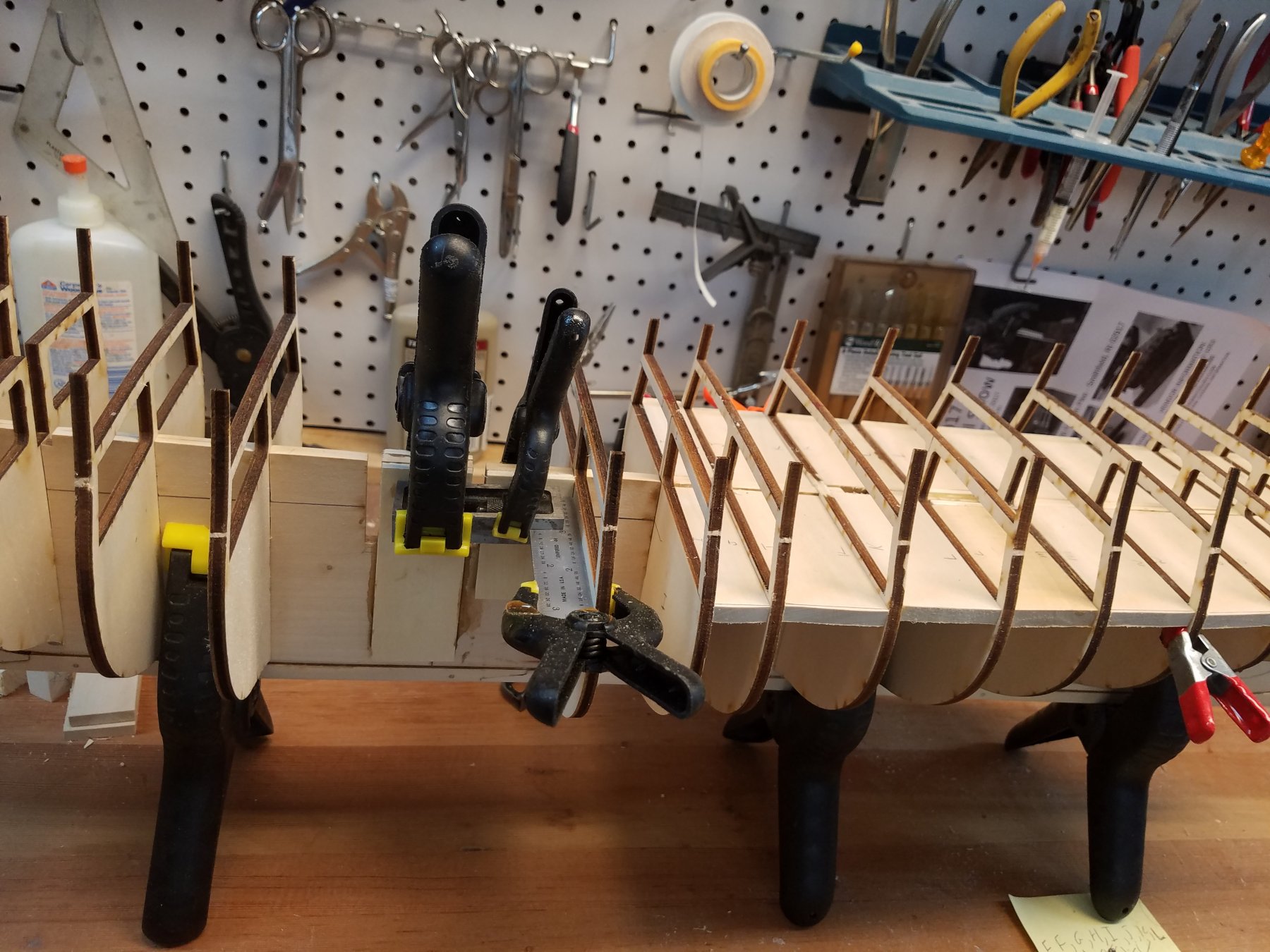
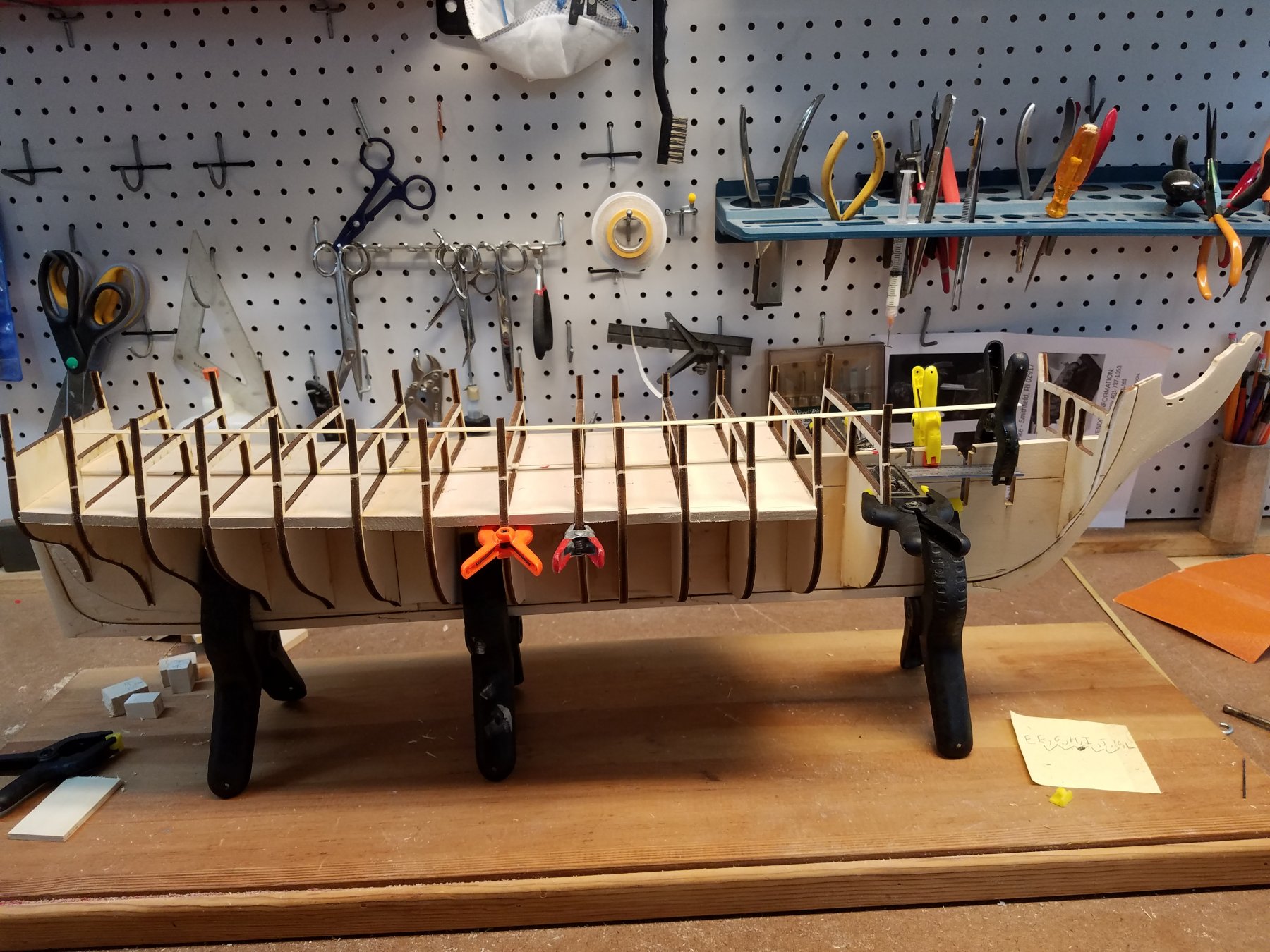
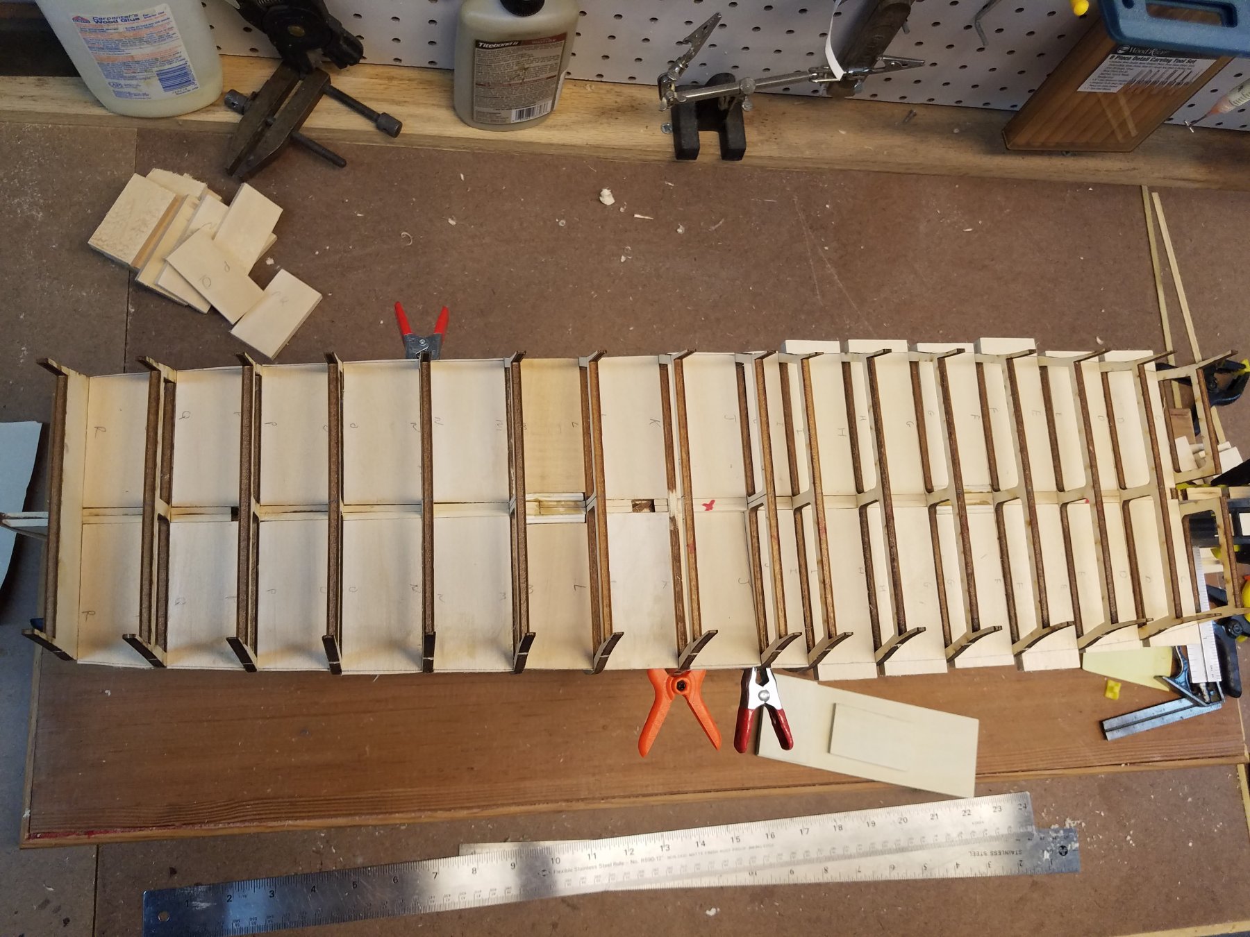
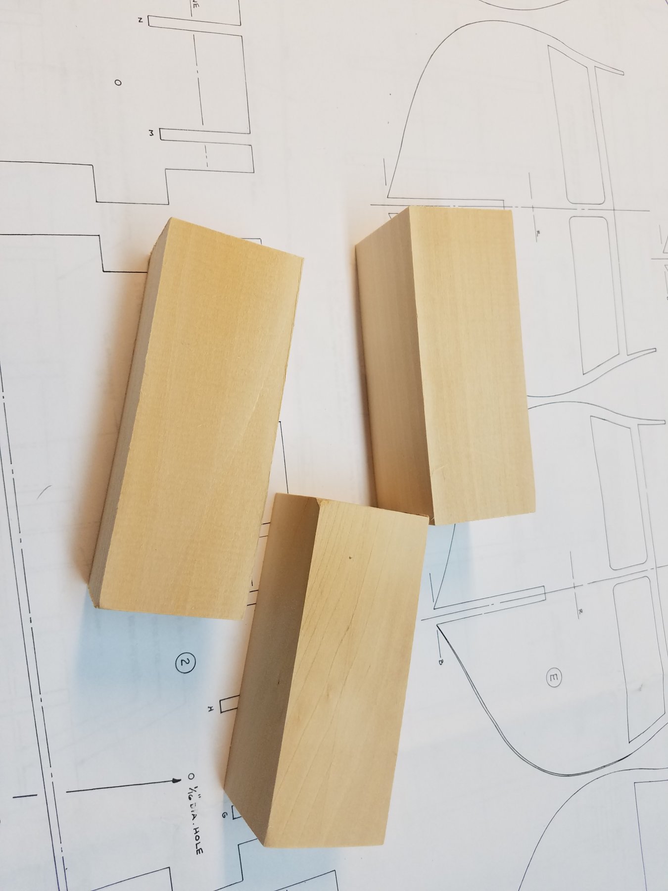
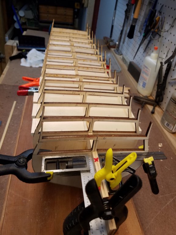
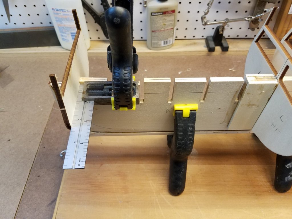
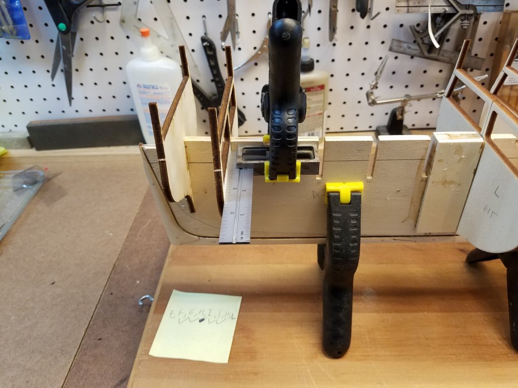
Next Update. I went through all the bulkheads and tweaked /adjusted mostly the height to make sure the top of the gun deck was flush with the top of the frame. Then.. I started gluing the bulkheads in. Starting from the stern with bulkhead R first. Used a small square clamped to the frame to ensure the bulkhead is square. It stayed in place until glue dried. Thus making the process slooowwwww. A few minutes to prep and glue the bulkhead. Then wait a few hours for glue to really set up. Repeat. Number 2 (Q) I'm currently up to bulkhead K. So, as I progressed with gluing bulkheads while glue was drying... I started to work ahead on those struts that will go between the bulkheads and will stiffen up the frame, keep the bulkheads square and be the base for the gun-deck. Started with some 2"x2x6"" basswood blocks I got at Michael's Slices them into 5/16" thick slabs on my band saw.. Measured the distance between the adjacent bulkheads, cut pieces to fit and... Note the struts are not glued. They are a snug fit. (And only in place for bulkheads where glue is fully dry). I used a digital calipers to make sure the pieces were the correct uniform width to fit between each bulkhead. Also ensured the matching piece on the other side was identical width. That ensure it keeps bulkheads square. Even without being glued in yet. it really stiffens and strengthens the structure. Now... I've run into a dilemma with those struts that I need to solve before I glue them in. Looking at the plans.... there are scuppers and portholes shown below the gun-deck's, gun-ports.. IF those are located at or above or at the gun-deck level... all is good. But looking the plan. they might be just below the level of gun-deck. If so... they would be right where those struts would be. So scuppers and portholes looking into the end of the struts would not be good. Next thing to solve. Because I'm doing an 1812 version with the open waist. I need to cut out the support post for the spar deck beams in the area of the waist. This is bulkheads E and K. And then later remove/replace the entire beams for bulkheads F,G, H,I J ( similar to what UsedToSail did.) I was thinking to remove them before gluing the bulkhead. Thinking its much easier to do this first. Soooo But, After removing the first one. It does make the entire piece (beam and bulwarks) quite fragile. So its probably better to leave them alone for now and cut them out later when I'm ready to start work on the waist. However.. they're easy to break while cutting them now while unattached. I'm concerned it will be even more susceptible to breaking when trying to cut them out later when there is far less room to work and get at it with the tools.... What to do??? K


-
Correct Usedtosail. Trunnels.. Not tunnels. (Wish I could blame Autocorrect on that :-) Other than the guns in the waist. I don't plan on rigging the gun deck cannons. I don't think any gun rigging would be visible peering through the gun port. But I'll confirm that when I get to that point and decide then how much gun tackle (if any) to add. Current progress is slow. I'm eager to start gluing the bulkheads. But this part needs to be right to have a good run of the hull and deck... so I'm taking my time. Been going through each of the bulkheads and transferring lines. Bulkheads A- I face forward towards bow. J - R Face aft. That way the bevels go along with the sight bevel left by the lazer cutting of the frames. So on each bulkhead.... I marked. 1) vertical center line. 2) Center line on the top of upper deck beam to align the king plank. 2) Reference line "R" to match corresponding "R" line on frame 3) Top of gundeck carried onto bulkwork and spar deck support post 4) Marked the edges (both sides) for bevel Round #2. All the bulkheads marked up and back in the frame... Dry fitted only By marking the top of the Gundeck on the support posts... I can line these up with the top of the frame. And that should allow me to get the right height of all the bulkheads in the slots. And I then put some battens on.. just to see how things line up. The Battens show the run isn't perfect but not too bad either. The run of the deck is really good. Only some minor tweaking is needed. A few bulkheads do need some shimming on their edges though. Note: I marked but haven't beveled the edges yet so that could help the run a bit too, before I add shims. I plan to both bevel and shim after the bulkheads are fixed in place. Other progress I made. I did taper the stem and stern post. And I also added the braces to the 2 joints in the frame (both sides) I took a piece of basswood. cut to fit the full height and with between the adjacent bulkheads. That way it not only does it add strength to the frame. it also adds support to bulkheads on either side. Last thing of note I did. I have the CD from the US Constitution museum with the historic and restoration plans. Took that to staples and had them print the gun and spar deck layouts scaled to fit to 24"x36" Taped them to the wall. Cool looking and great to reference. Now its back to work Mon morning. So no more time in workshop till next weekend.


-
UsedToSail, I went back and looked at your log again relative to the gun deck. Looking at how you did it is making me re-think my planned approach. I like the tunneling you did. really adds to the level of detail. And working on the false deck off the model makes it a lot easier to do a good job. Not sure if I could pull that off the way I intend to to implement. So you got me thinking how I might adapt. :-) Generally, I like to have all my gun ports open. And as such, all the guns need to be real and on carriages. I don't like the look of fake barrels (when the ports are open and its obvious they are fake). I'm not detailing the whole gun deck. Just near the open waist plus the real cannons. But the deck does need to run the whole length to support the real cannons. My planned approach is to leave the bulkheads and top of the frame at the current height. Not cut them down. I will cut the braces for the deck beams near the waist. But I don't plan to cut the beams themselves off. I am going to put struts between all the bulkheads to stiffen and strengthen them up and keep them square during the planking process. Soo my thought is to have those struts basically act as the false deck fitting them flush with the top of the bulkheads and extend from the frame all the way out to the side of the hull. For planking... I have strips left over from another build. These are 1/64th inch thick (very thin. They were supposed to be a second planking layer) and I can cut these down to the proper width. Since the tops of bulkheads are at deck level... My deck after planking will be 1/64" too tall. (That will be invisible to tell by anyone including me... so its good enough :-) BUT, then then gun barrels will now be too high and that will be noticeable. And another problem I typically have with real carriages... is that the wheels are so small, there is barely enough surface area for glue to hold in place. Then they break free later during the build when they get bumped. (and impossible to fix as its now enclosed in the lower deck.) Sooo to solve both issues.. I was going to file a 1/64 flat on the bottom of the carriage wheels. The cannon will then sit at the right height and stick better to the deck. I can also put a small shim under the carriage (same height as wheels to further add surface area. That's my current plan. Comments, suggestions, any potential issues you see that I might be missing? The downside of all this... is that with my fat fingers.. I cant get as much detail down in the waist ...working below and between those deck beams. So thinking out loud.... is there a way to add simulated tunnels to the deck planks... before installing them? And keep them lined up when laid down?? Any ideas?
-
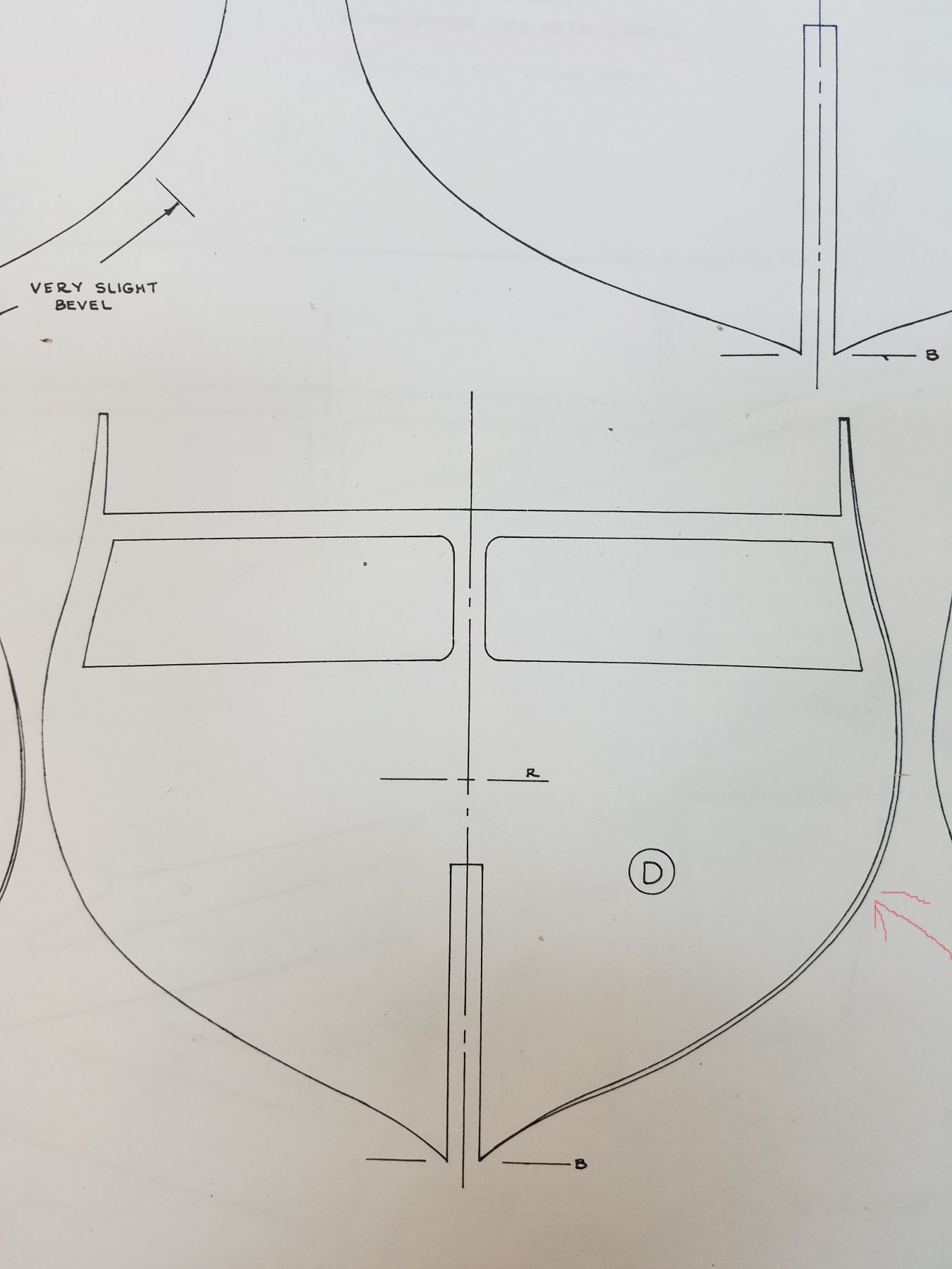
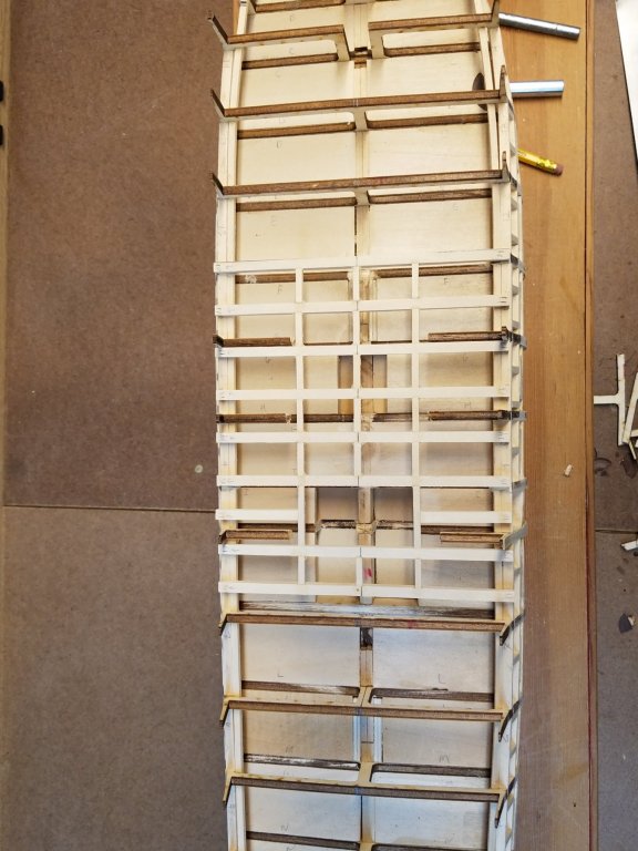
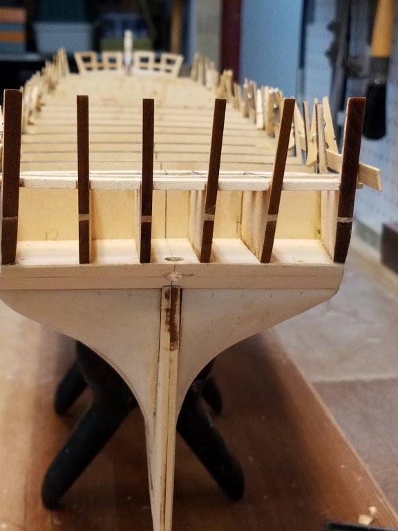
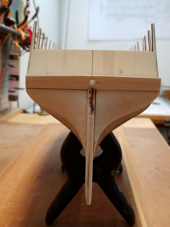
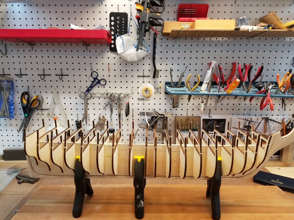
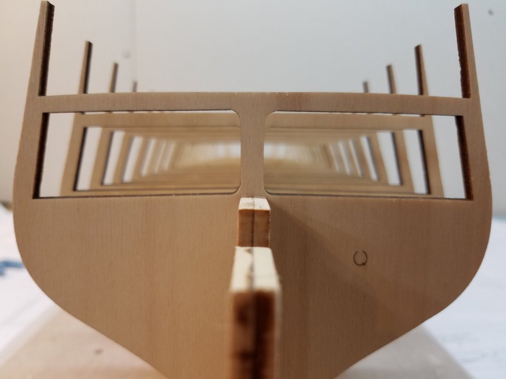
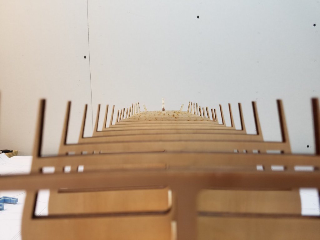
Sooo. Does anyone know if Model Expo might have fixed the plans or bulkheads (or both) since the asymmetrical bulkhead issue was identified? I ask because while I haven't checked them all... I spot checked a few bulkheads that were supposed to be the worst ones(B, C,D,E)....and mine look fine. I'm not seeing the issue. CaptainSteve mentioned.. he thought one side of plan was different to show the beveled edge. But if you look at my bulkhead D blueprint. The bevel line is indicated on the right side. But also the full profile on both sides. When I put the bulkhead on the plans... it matches the full profile perfectly. And again matches when I flip the bulkhead over. The vertical center-line is square and centered. Did the original plans maybe only had the bevel on one side. But in latter releases, ME updated the plans to show both bevel and full profile? Another quick non scientific test I did... Again not precise but the error should be apparent by eye. I dry fitted all the bulkheads. and then sited down the center from stern looking forward. (I left off the last bulkhead R that is solid) If there was a misalignment of any one or more bulkheads... then when looking straight down the deck, The center support posts (for spar deck) of any misaligned bulkhead should be obvious by not being directly inline. But as you can see.... they align perfectly. Not as obvious from the pic. but the horizontal top of both gun deck and spar deck also align and look perfectly parallel by eye. Same goes for sighting down the spar deck. all the bulwarks on both sides look even and symmetrical all the way down. Again, I would think that if on was even slightly out of alignment. it should really stick out and be apparent? Obviously this is not scientific, and I will cross check every bulkhead against the plans. But I guess my point is, my bulkheads seem to be in "perfect" alignment. So Did I get really lucky (doubtful) or did ME fix the issue in later issues of the kit? Or was the issue intermittent / not consistent across every kit? Were there any other Connie build logs where the modeler didn't have the issue? I'm expecting to see the error and looking for it. but not finding it. that makes me worried. K

-
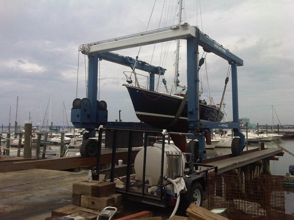
Markku, I had heard about the nonsymmetrical issue with some of the frames from other builds logs. So I'm going to watch for them when I put the reference lines on the frames. Thanks for pointing me to your build you're log. You have the best/clearest description of the problem I've seen. I'll definitely use that info to fix mine. TomS, Also welcome to the Connie Club as well. I think Me, you and Markku will all be in roughly the same phase in the build together ...so it will be great encouragement and motivation. Also search the forum. There are a large number of Connie builds to draw knowledge and inspiration from. I'll singe out usedtosail among many. Check out his log.. He not only has a incredible build.. but he turned his log into a practicum for us to follow. :-) No model pictures today, but I did make some progress. I have the rest of the keel and stern-post glued on. Sad day for a sailor though... End of season, My non-model boat got hauled for winter today. After Connie, I may need to make a model of her for the day I become Usedtosail II. but that's a long way off.


.jpg.20dd5d2737c020cc0fa1a828ae9922c4.jpg)