
MORE HANDBOOKS ARE ON THEIR WAY! We will let you know when they get here.
×


kmart
-
Posts
195 -
Joined
-
Last visited
Content Type
Profiles
Forums
Gallery
Events
Everything posted by kmart
-
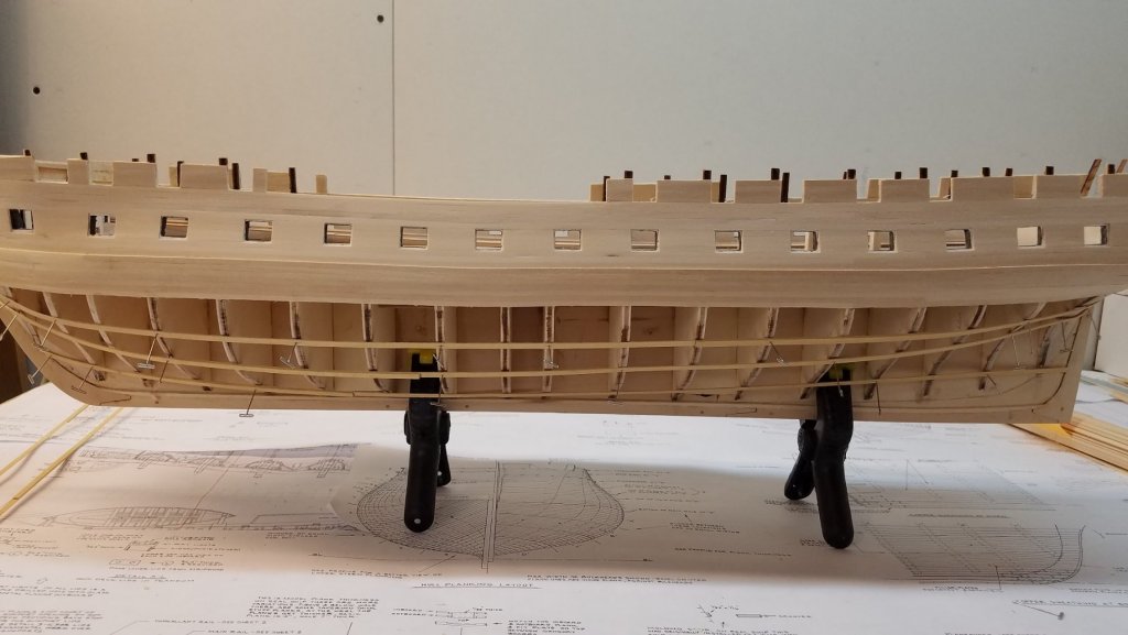
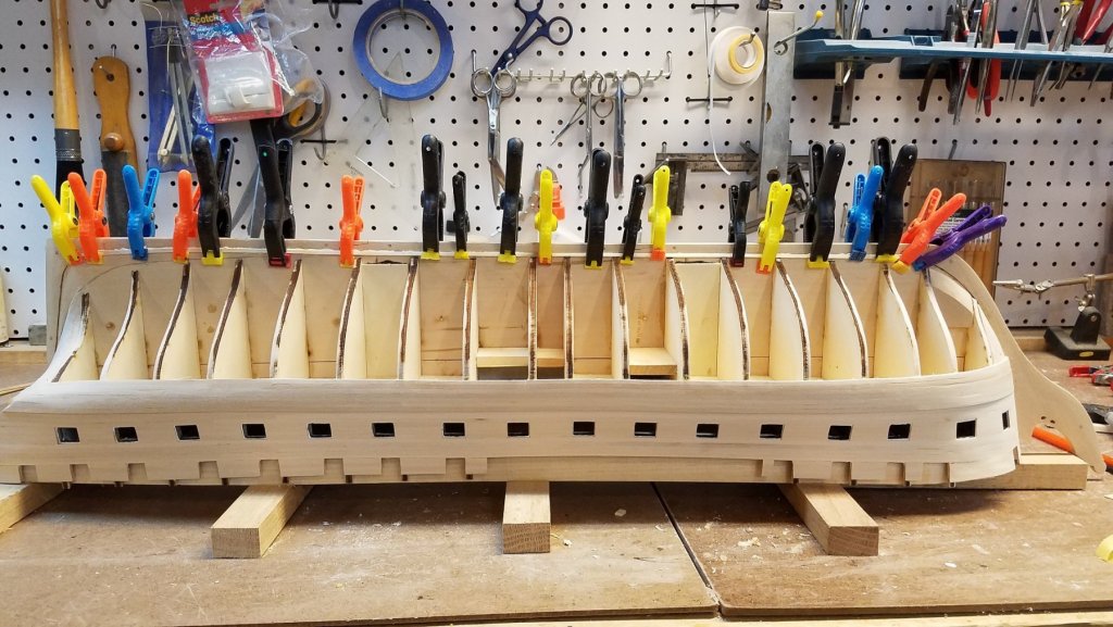
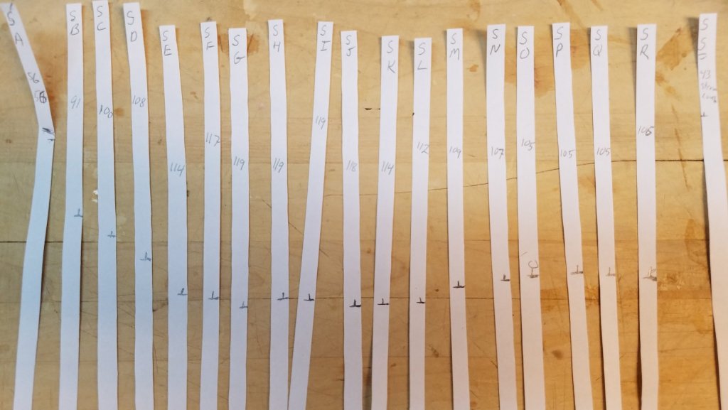
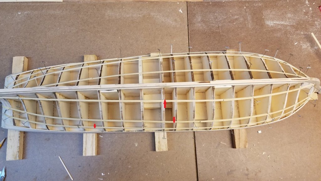
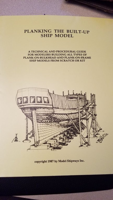
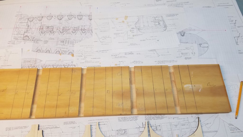
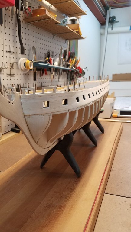
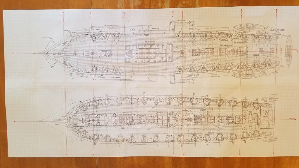
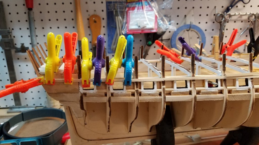
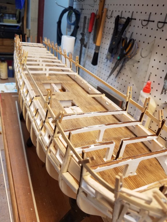
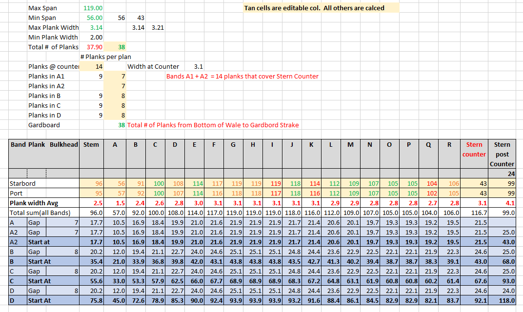
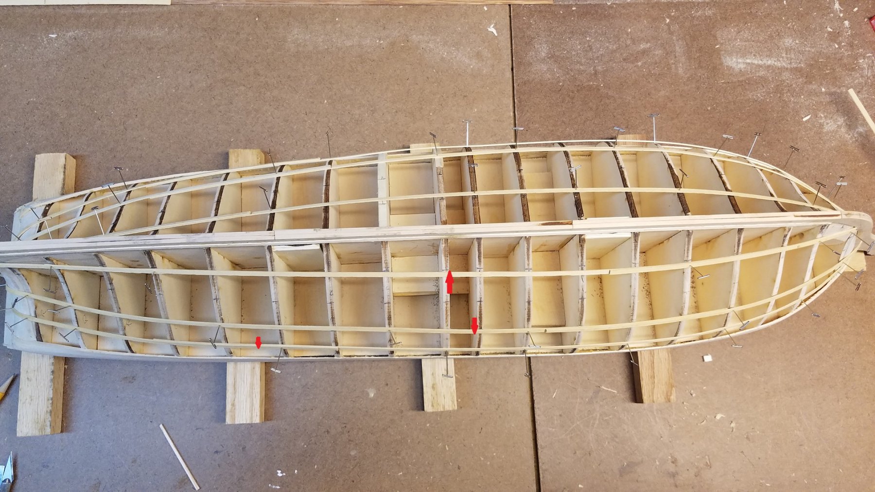
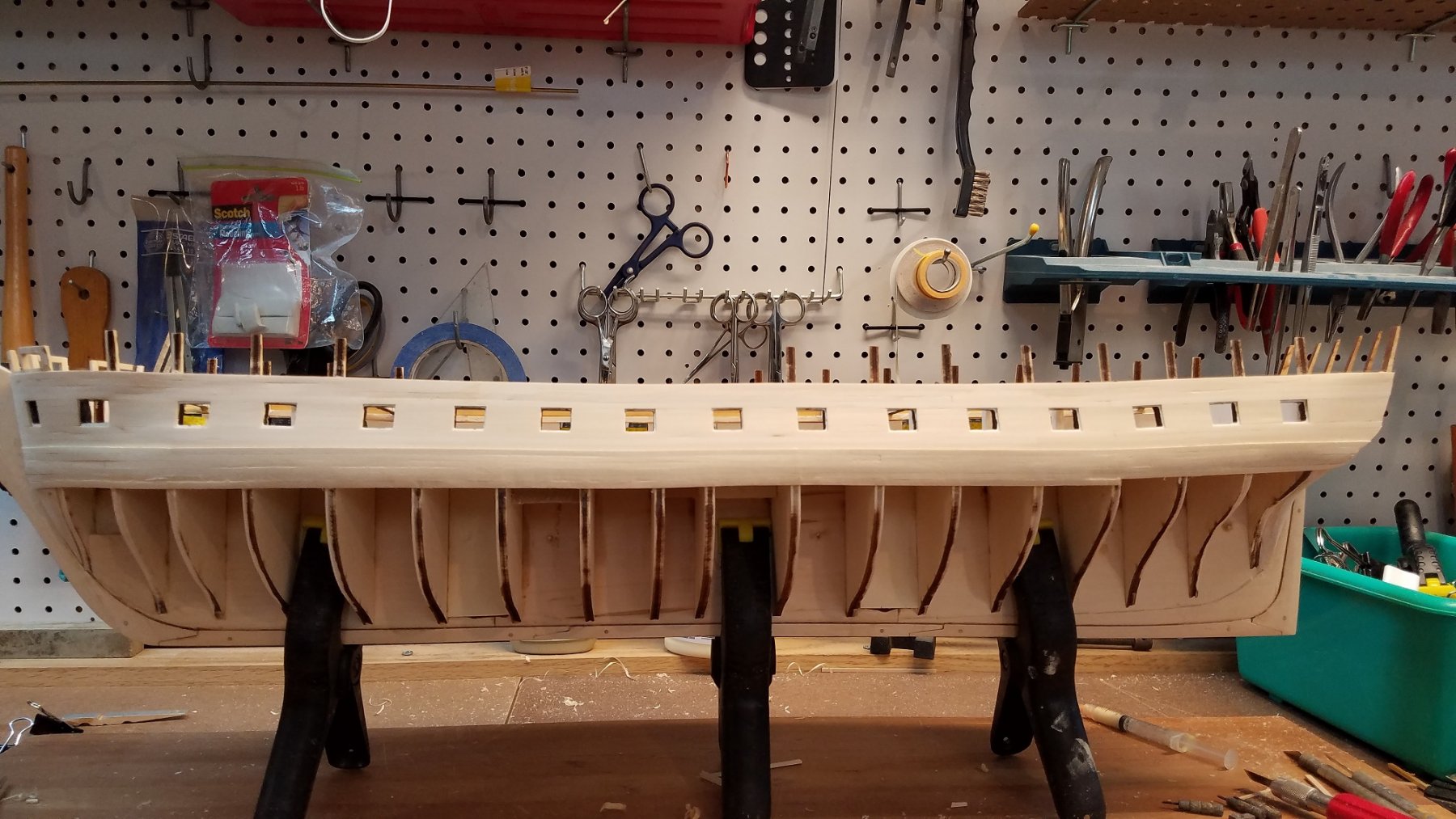
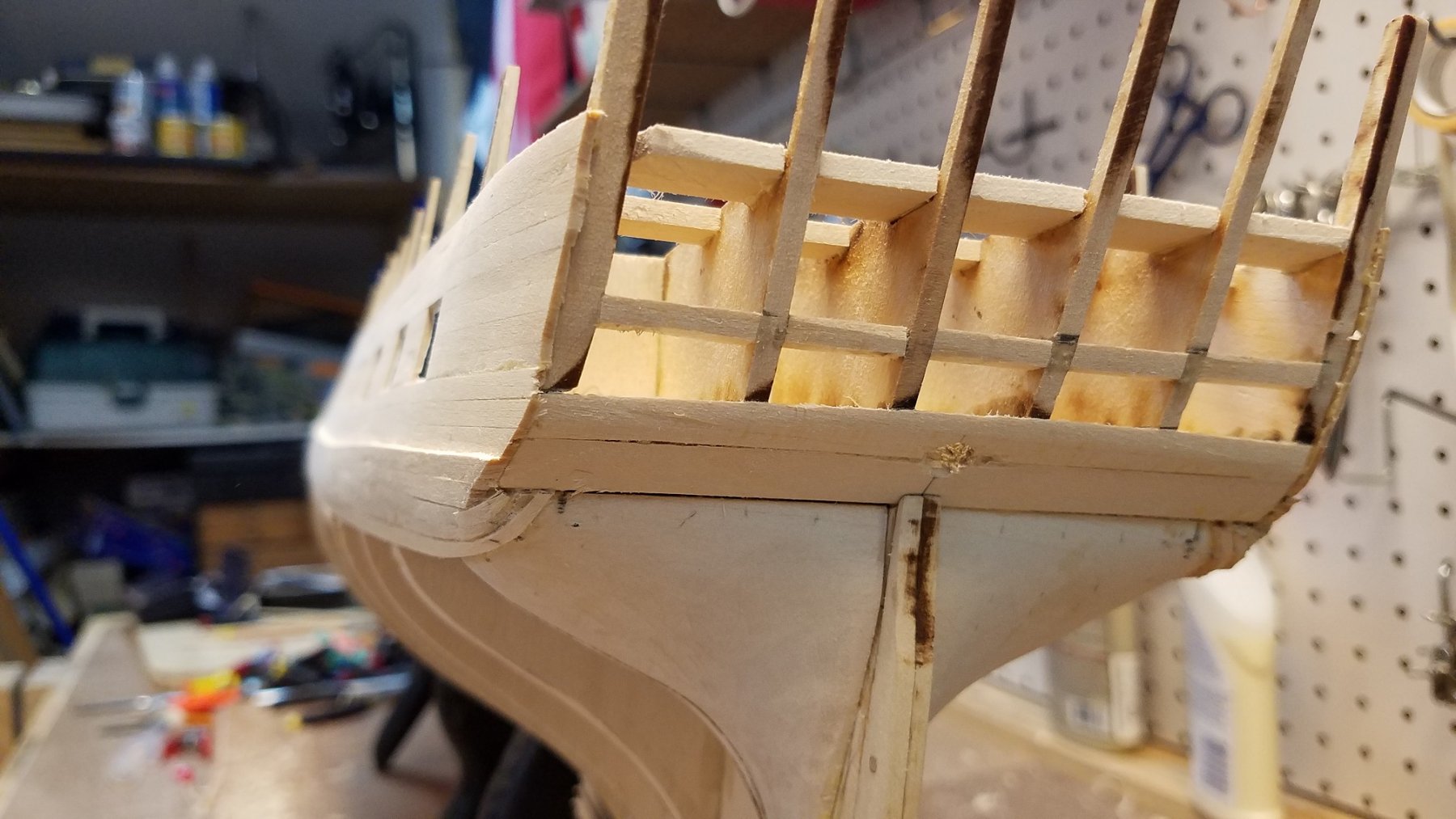
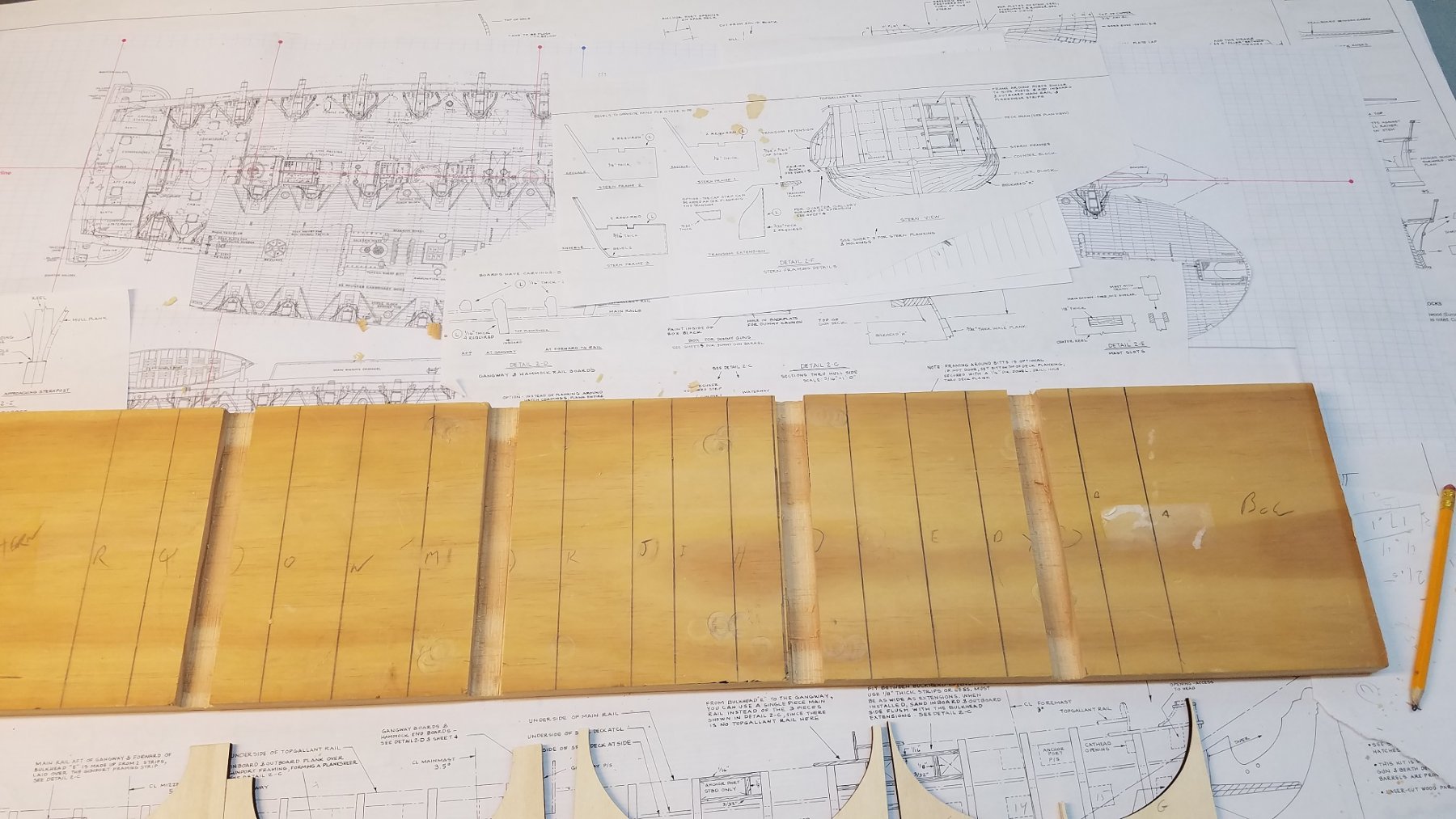
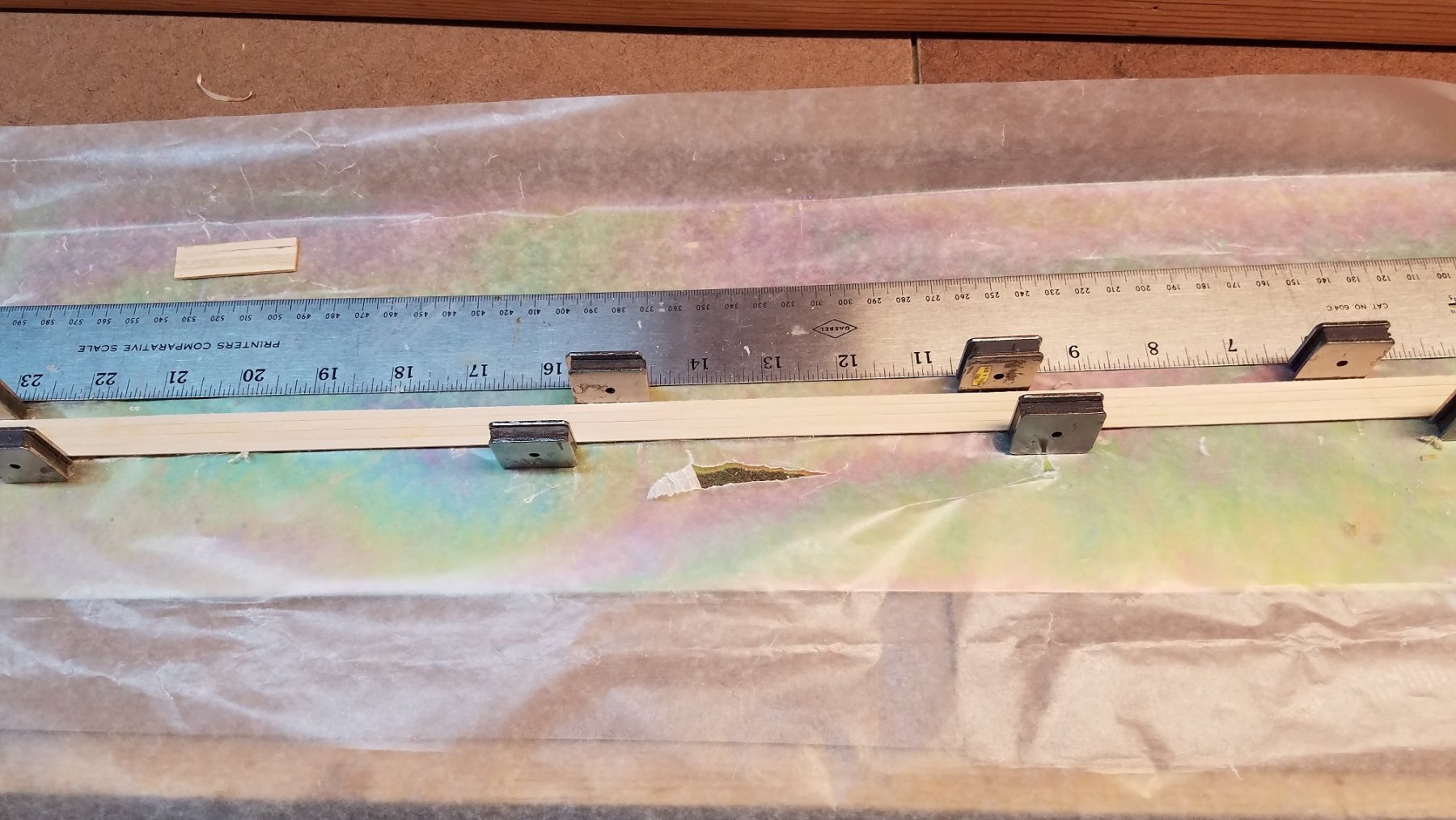
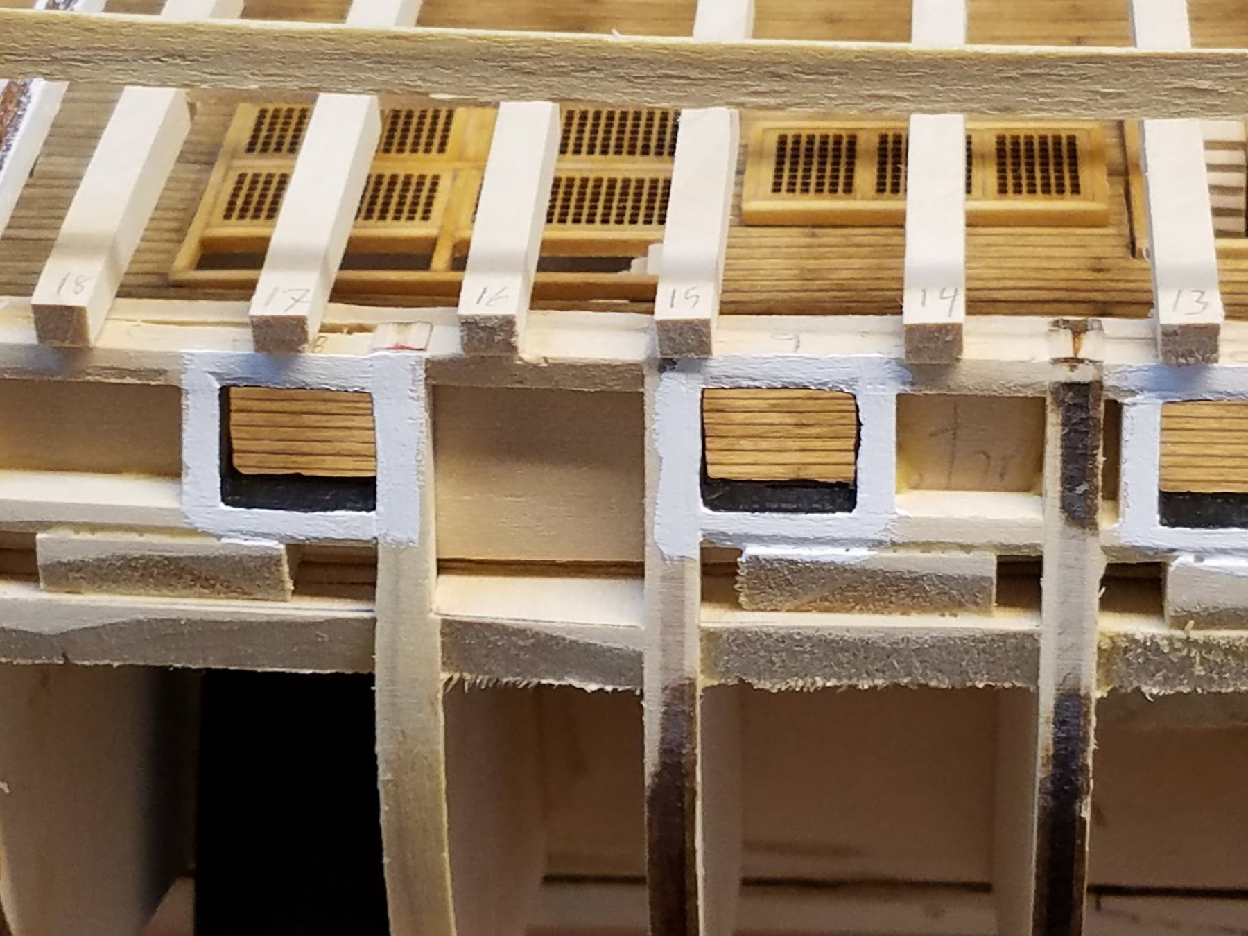
Thanks Used2Sail and GMO2. I'll go with the 1812 version on NOT have the top-gallant rail. Will just have the rail end over top of the spar-deck gun-ports. Haven't posted in awhile but have been making slow progress. Added the filler pieces that will be used to support the spar deck gun port frames Used my gun-port Jig to keep them square and symmetrical Once all the filler pieces were in. I went and planked and sanded the outer planking. Cleaned up the gun-ports. Next to prep for planking the rest of the hull. First, pulled out my handy planking reference book. Supper helpful in understanding how to layout the planks Put in the gard board strake. Once gardboard in.. I made a bunch of tic strips. used them to measure distance from bottom of wale to gardboard at each frame as well as stem and stern In the process i identified that a few of the bulkheads were not quite fair .. So I needed to correct that with some strips on the low bulkheads With the tick strips all made, measured... transferred the info into an excel spreadsheet. Overall the hull is quite symmetrical. Of the 18 bulkheads + Stem & stern ... Of the total gaps at each frame.. 8 were identical port to starboard, another 8 had only 1 mm difference. There were only a couple off by 2 or 3 mm . All close enough that can be corrected within 1 or 2 plank adjustments I divided the hull into 5 bands. A1, A2, B, C, D A1 and A2 together have 14 planks. These will cover the planks that terminate into the counter of the stern. After calculating the bands... I transferred the info back onto the tick trips. Then transposed the band info from the tick strips back onto the respective bulkheads From there.... I ran batons at each of the bands. The battens are positions such the edge is aligned with the band closest towards the wale or gardboard strake. This way I can work 2 planks per side at a time. One closest to gardboard and one closest to wale, Working inward. When I get to the 1st baton, remove it and keep working toward the next pair. At this point the run of the battons look decent except at the bow. The natural run doesn't flow up as far on the hull as I laid out. If I follow the natural run, then the taper will be too great at the bow. But if I follow my marks. I'm concerned the planks will take a unnatural bend upward and look more wavy, thain fair. Need to play with this and figure it out before I start laying planks Thats it for now. K


-
Hey, UsedtoSail I'm pulling up a seat to watch you turn this into a masterpiece as well! 🙂 Glad to catch you at the beginning on this one! K
- 131 replies
-
- 3
-

-
- santa lucia
- panart
- (and 1 more)
-
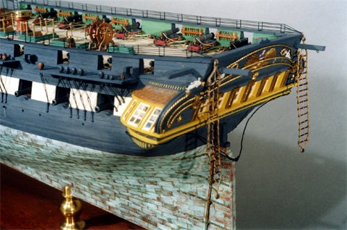
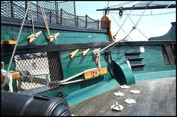
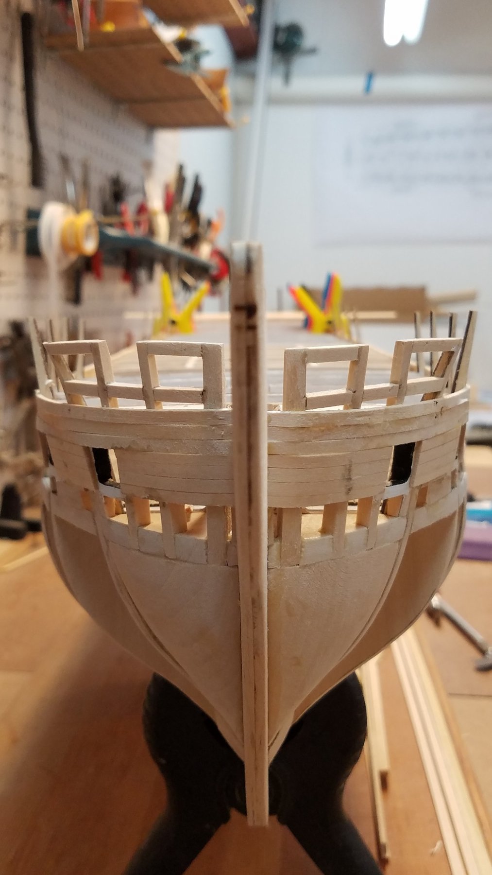
General Question for all the other Connie builder. Looking at some of the other builds logs ... (Used2Sail) And some pics of other historic models (see pics below) The top rail is right at the top of the Spar deck Gun ports. However, on the Model Shipway plans... and even in AOS under the 1812 profile view on page 47, There is a rail over the spar gun ports, but then there are 2 more planks above that rail and then the Top rail. Then the hammock crane on top of that rail. Are those extra planks a modern addition? Did the 1812 version end right at the top of the gun-ports? Current ship does have the extra 2 planks...
-
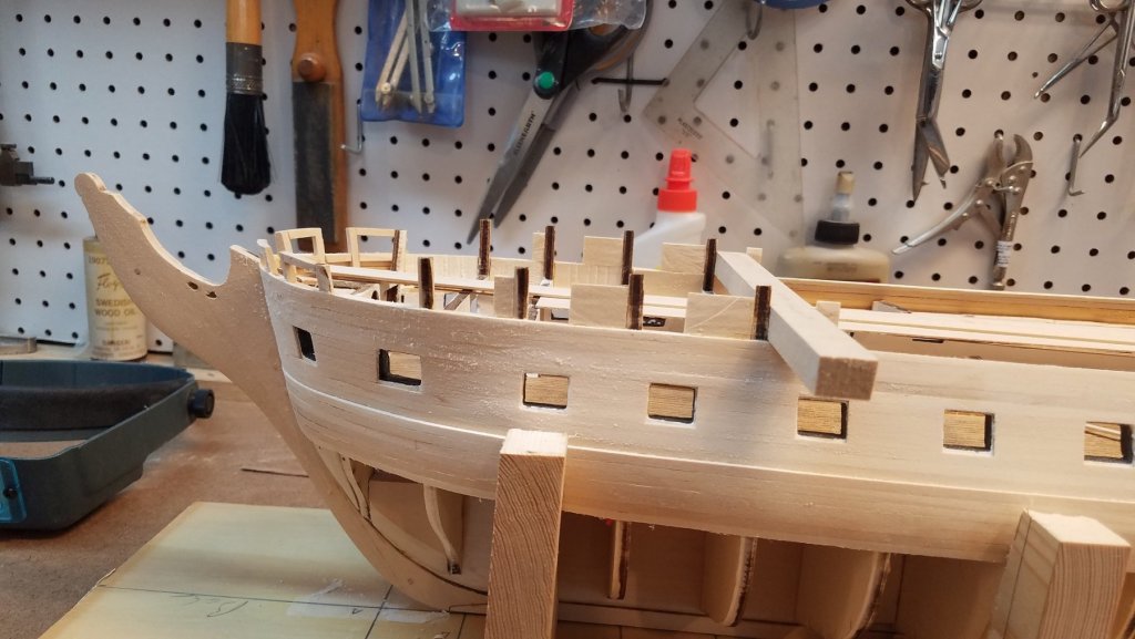
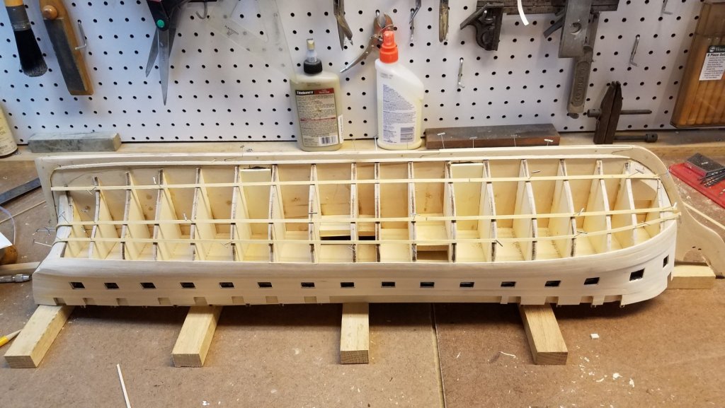
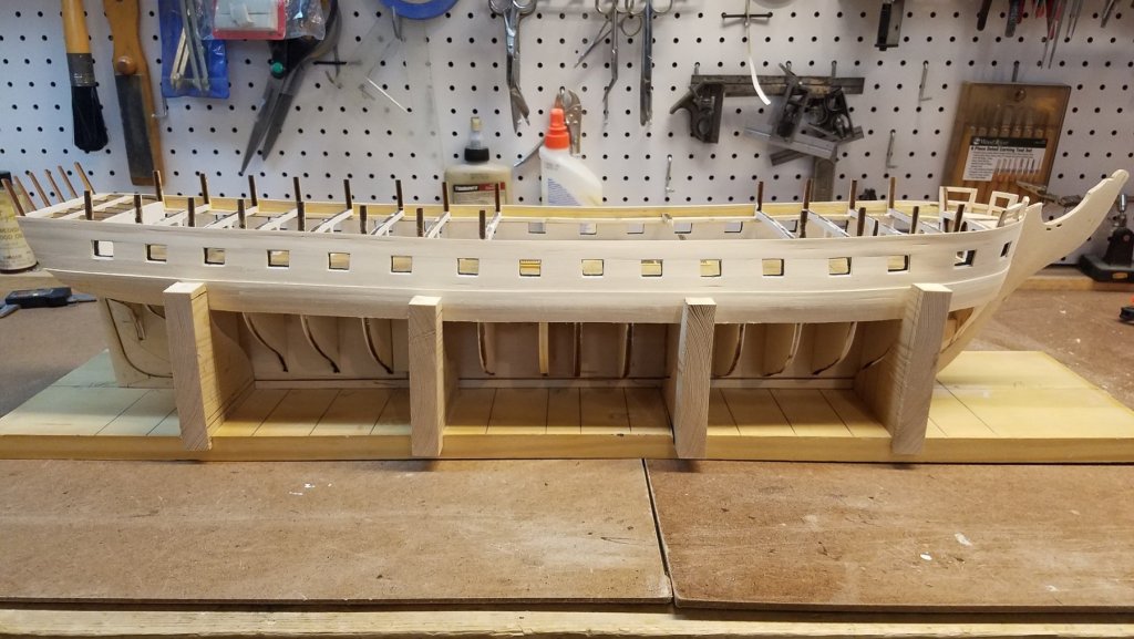
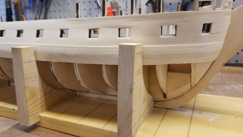
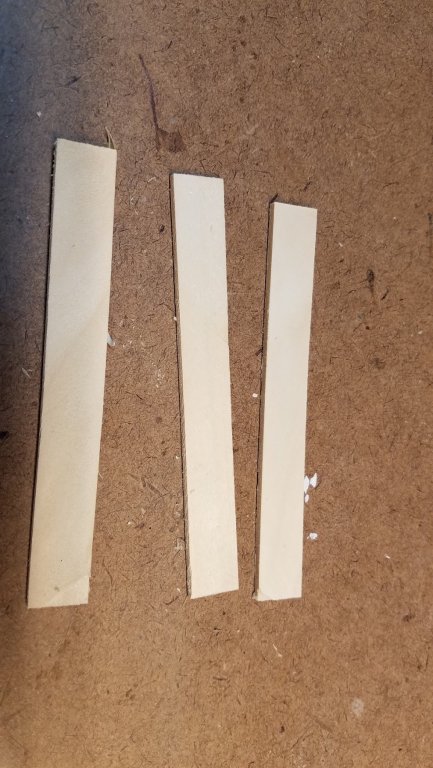
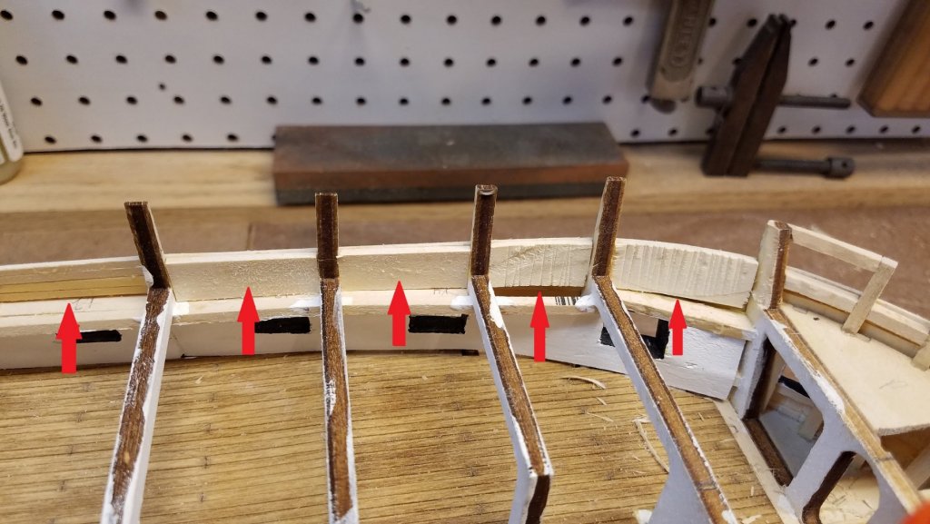
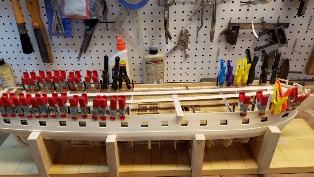
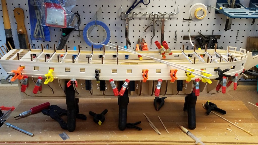
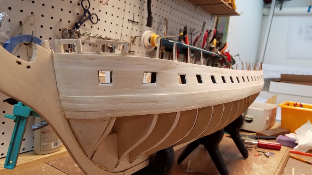
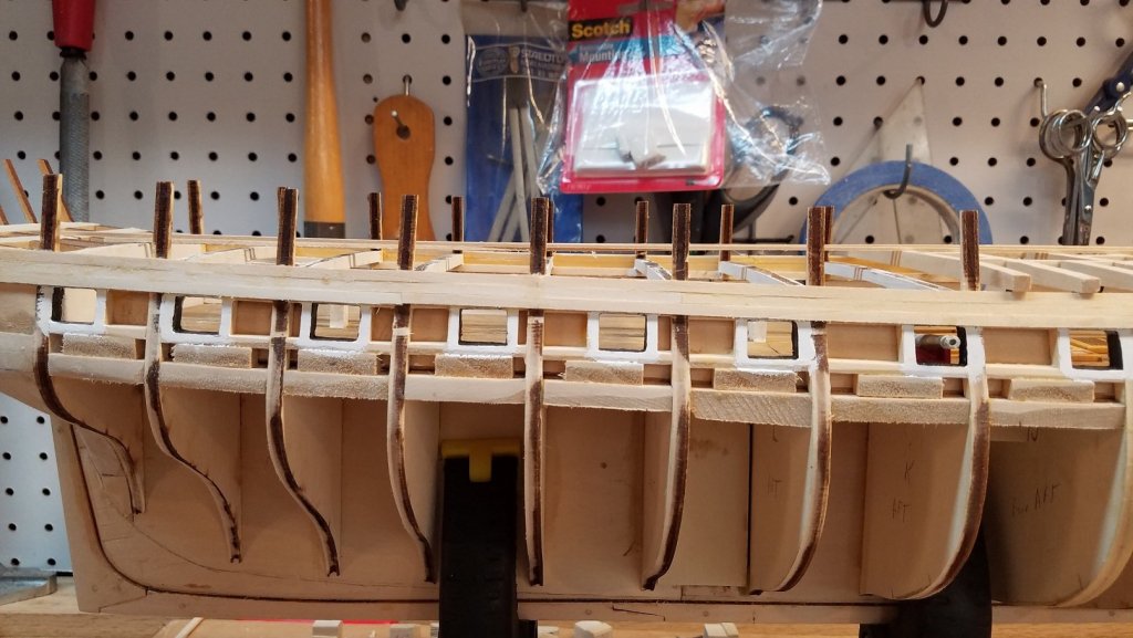
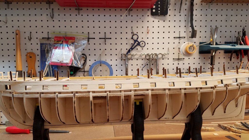
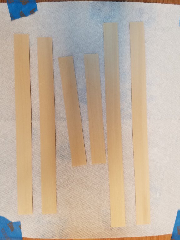
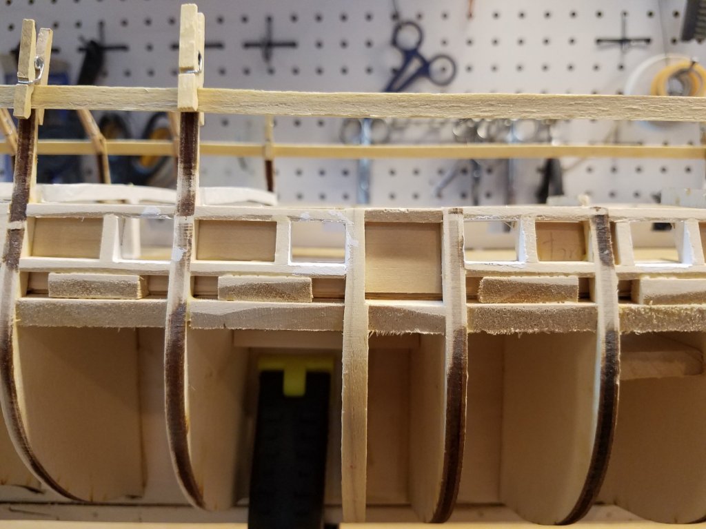
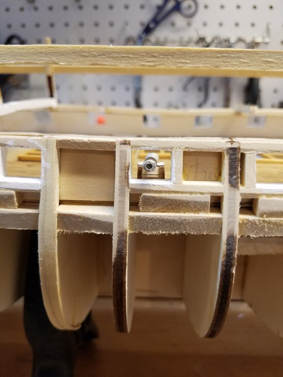
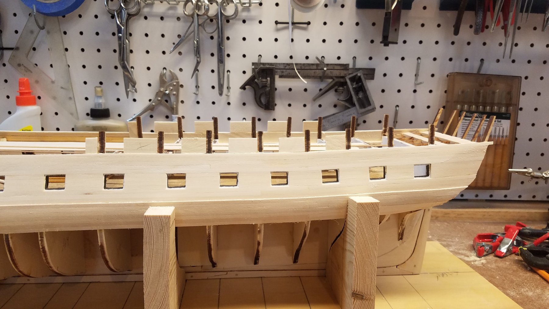
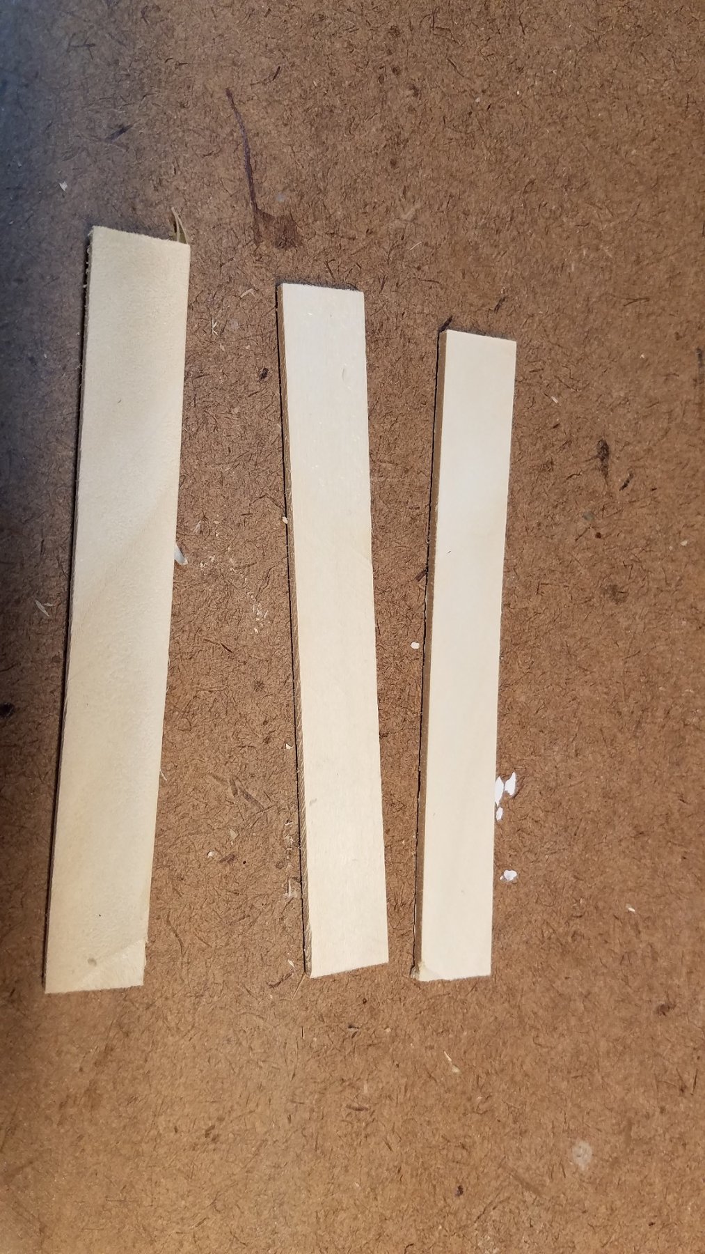
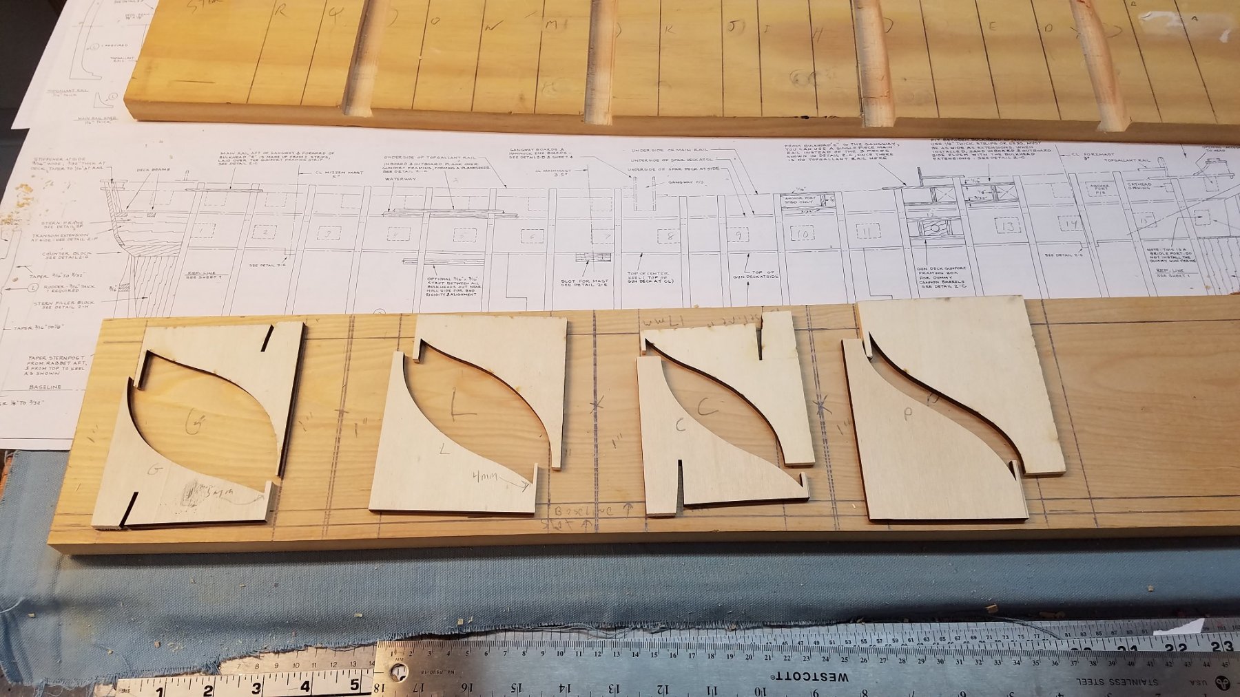
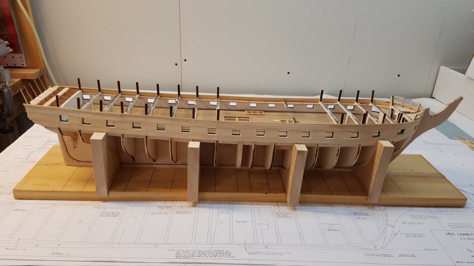
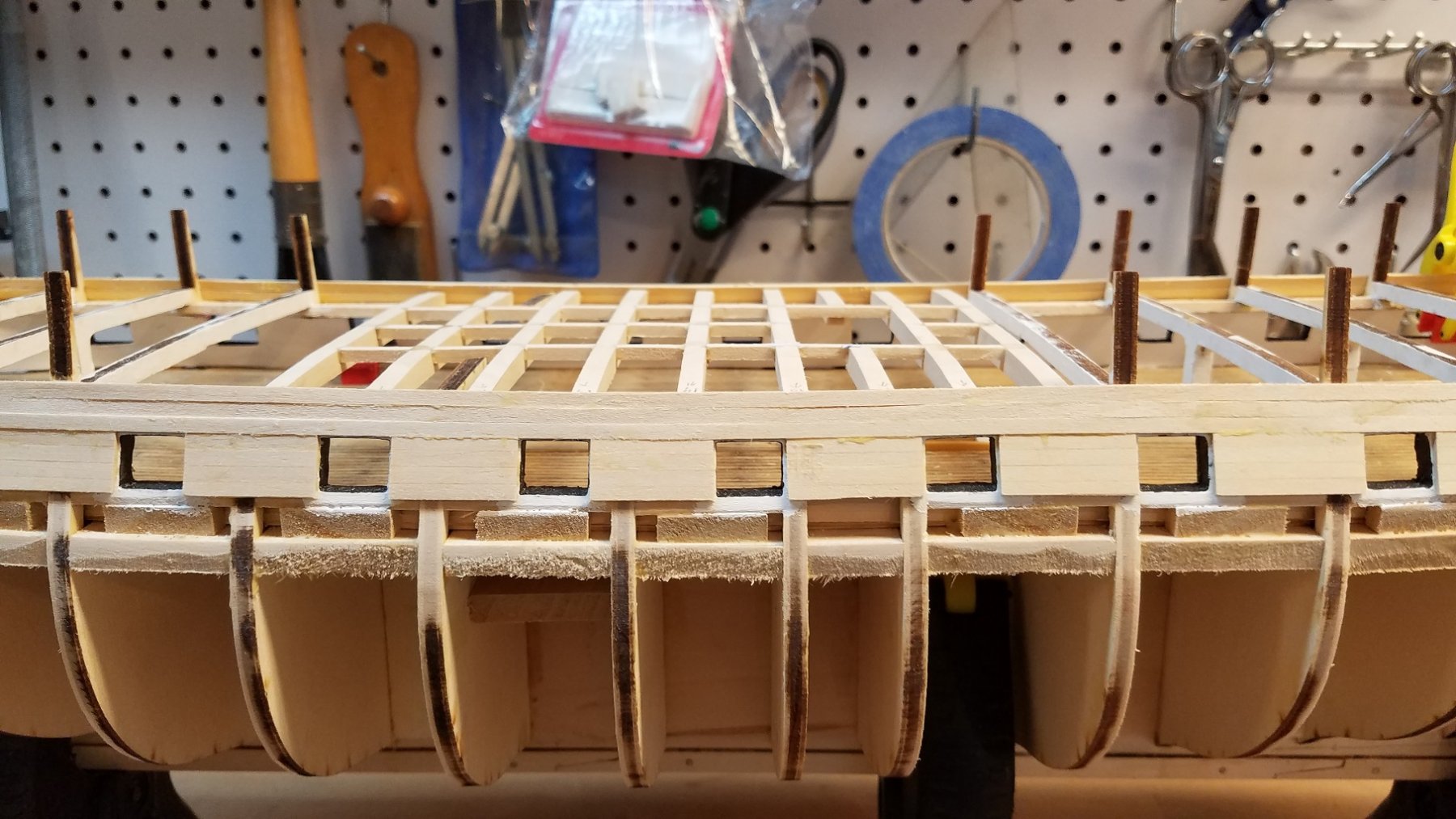
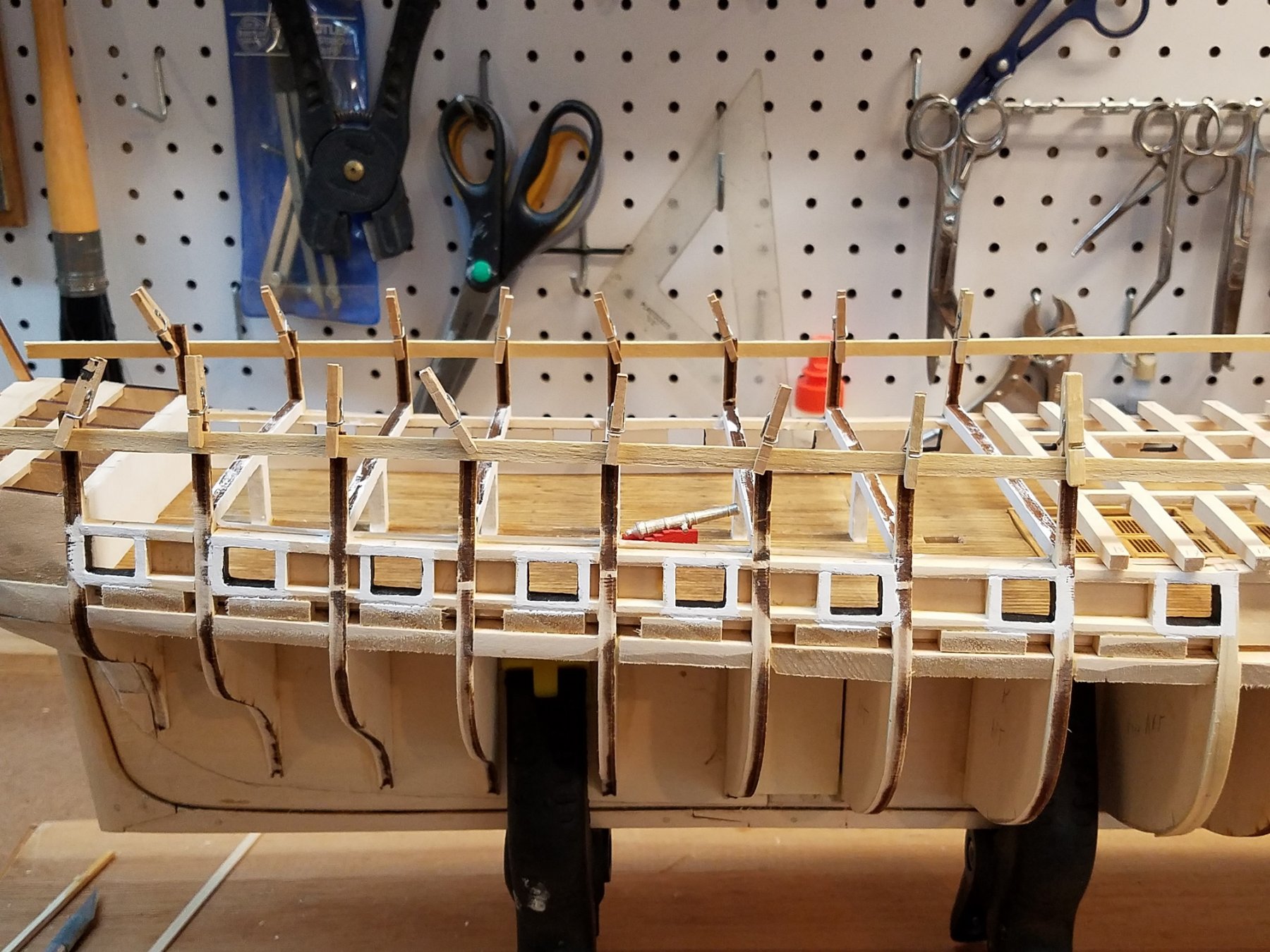
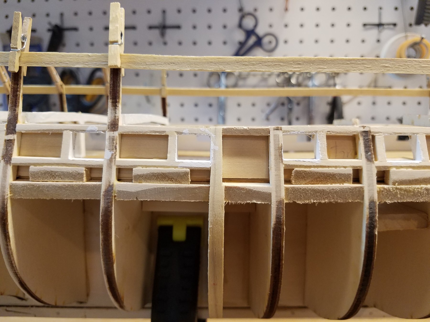
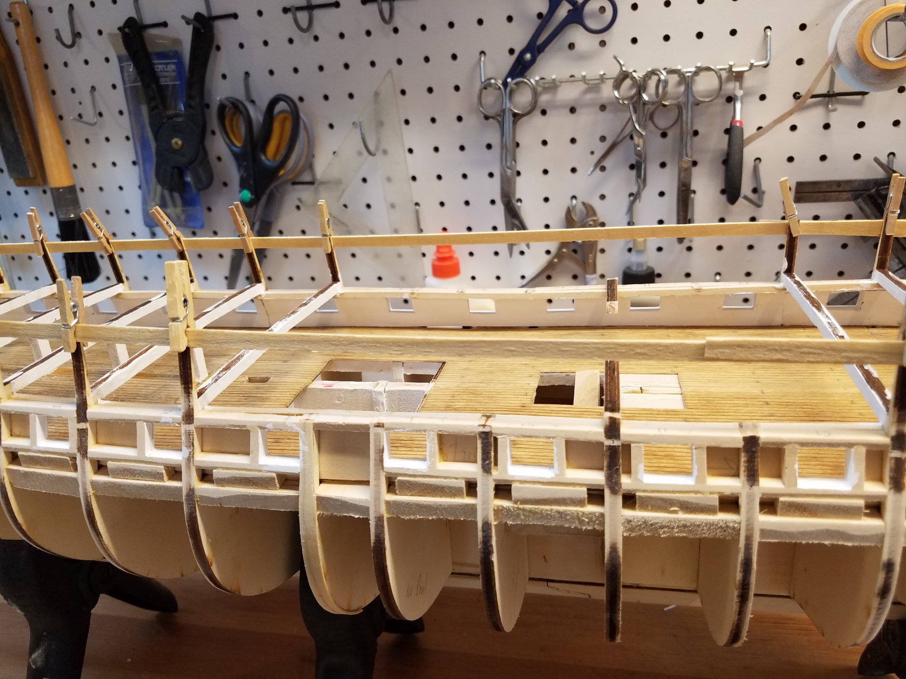
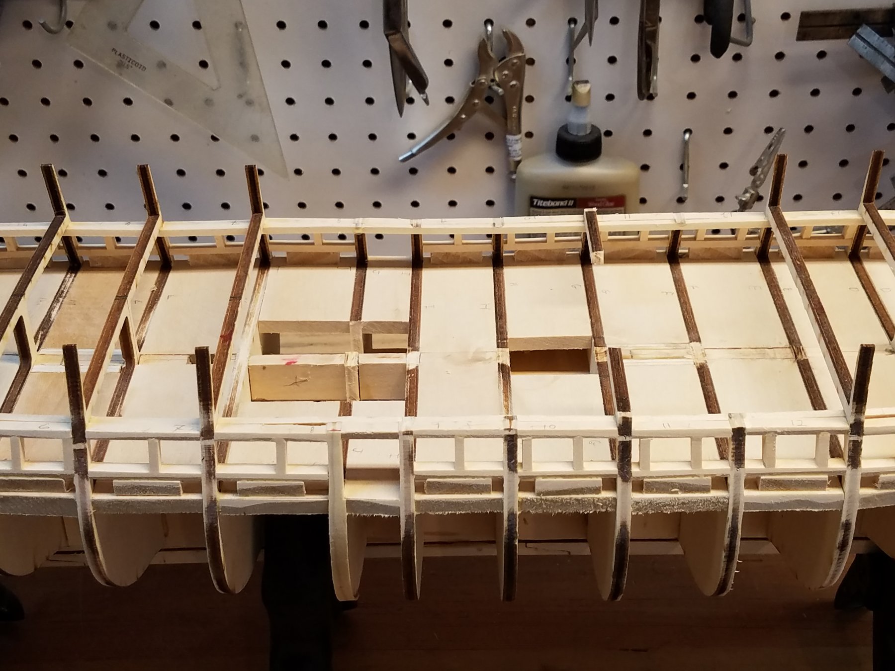
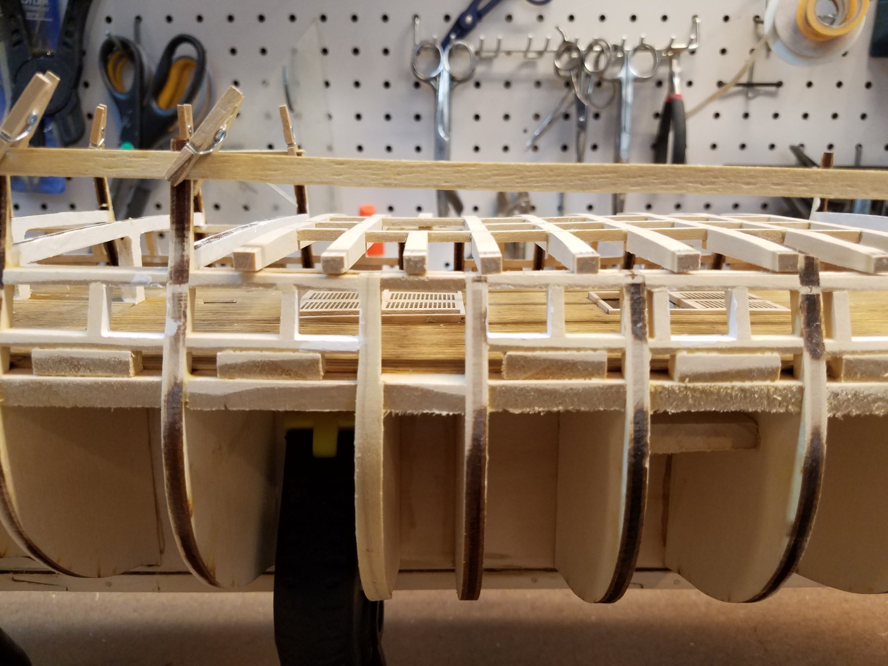
So moving along. I did get a fair amount done this weekend. 1) finished the wale 2) Finished the cradle 3) put in the plank-sheer. 4) started the framing for the spar deck gun-ports The cradle is working out nice, She sits perfectly level, and doesn't move at all even when handling the boat. Easy to move it around, spin it around, etc.. So for the Spar deck gun-ports. I added the plank sheer plank....the top edge of which is level with the bottom sill of the spar deck gun-ports. The top part of the bulwark is very thin and fragile. Hard to really frame in the gun-ports with just the bulwarks for support.. So I'm borrowing an idea similar to what Used2Sail did. I cut a bunch of basswood into strips the same thickness as the bulwarks top I trimmed them down to be 13mm wide. This is the height from the top of the Gun-deck (starting just under the spar-deck beams) to the top edge of the sheer-plank and the top of edge of the spar lower sill. Then trimmed them to fit between the bulwarks. See below. The first one on the left is not yet done. The next 4 are. This does a few things 1) Really strengthens the bulwarks 2) Give a nice solid lower sill for the gun-ports 3) really strengthens the outer planking 4) Gives a solid surface when I go to do the inter planking Finishing the rest of them. So that's the lower sill. Next weekend I'll work on the gun-port sides, For that I will just do more of the same. I'll cut some more pieces similar to the lower sill.. This time the width will be equal to the height of the spar gun-ports. (~4 planks high) These will glue on top of the current pieces and butt against the bulwarks. Once in place I can add the 4 planks that are at the level of the gun-ports. Then repeat the process 1 more time to make the top sill, and support the remaining planking up to the top-rail. Like I did with the gun deck ports.. I'll make a jig to ensure the ports stay square, equally sized and spaced with the port on the opposite side. That's the plan at least. KMart
-
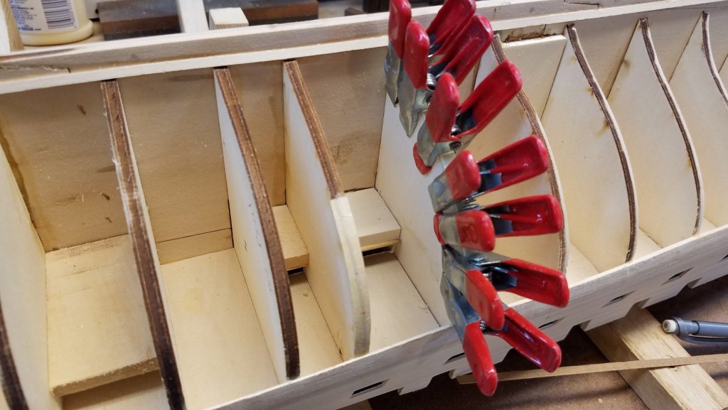
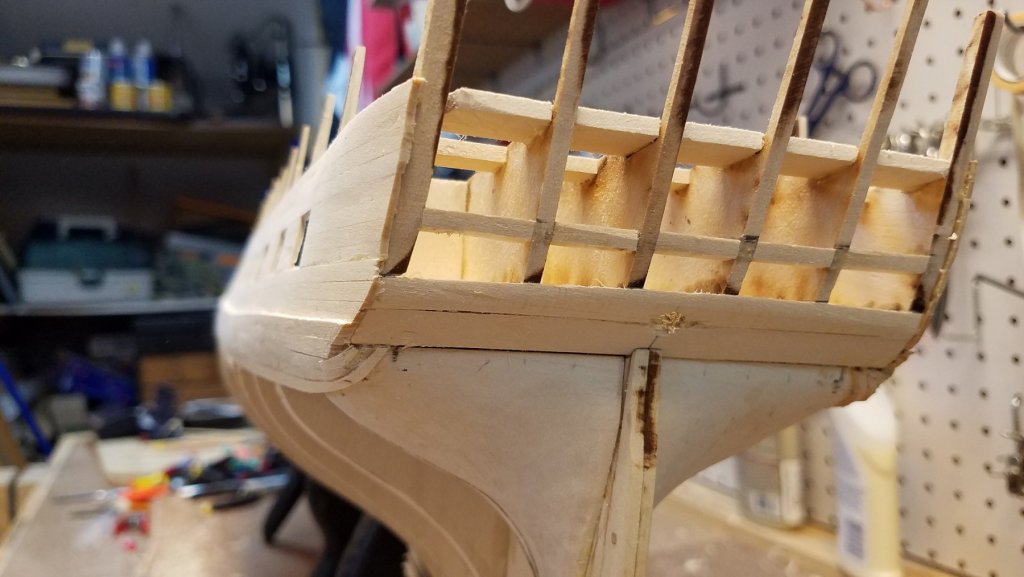
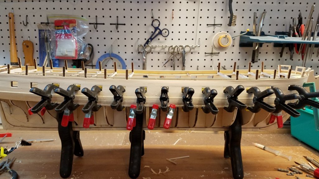
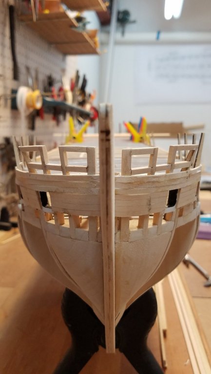
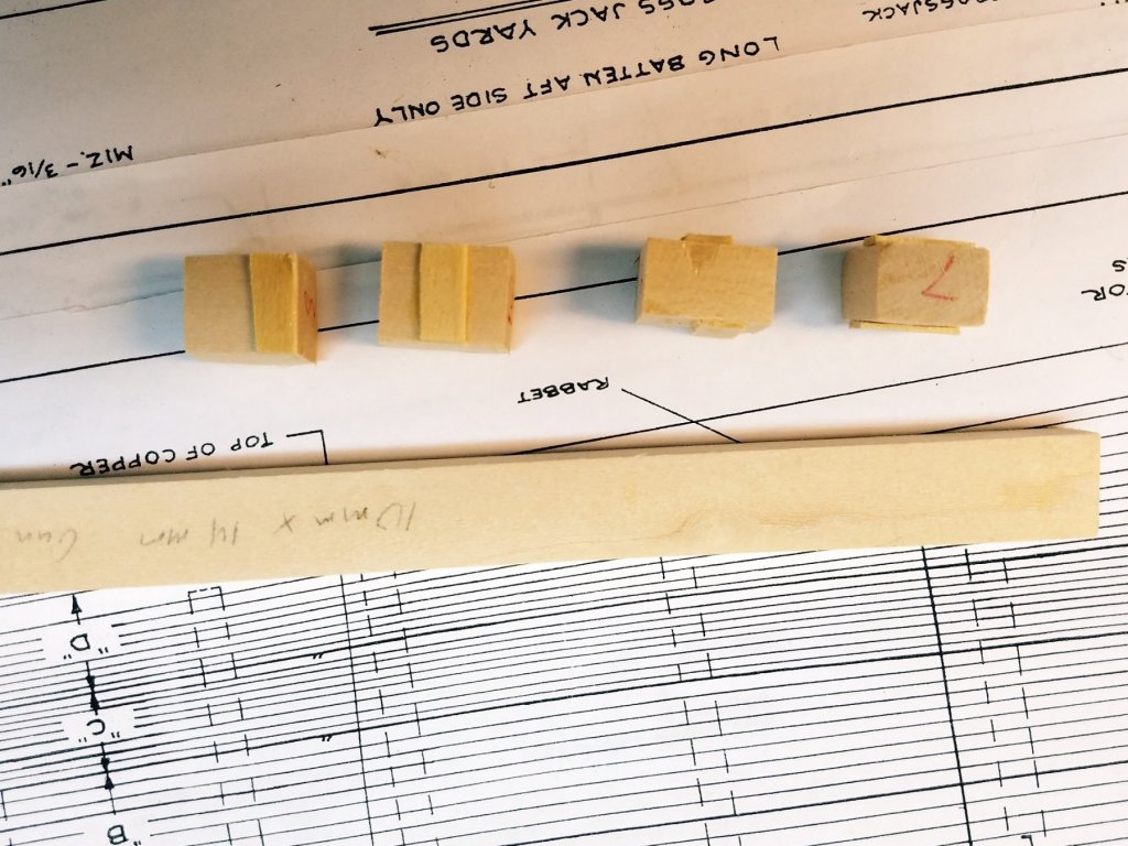
Vince , Yes.... when I saw that book at that price...I jumped on it. I actually learned about that book from your log. I've been following along your RW build for awhile now. You have a masterpiece there. And looks like your close to finishing as well. And I thought the Connie will be a large model when finished. The RW looks Gigantic. (and that's an understatement.) How/where are you going to display that when your done. 🙂 Back to Connie...... Next update. Nothing too exciting or interesting this time. Just added some more planks. At this point I'm working on the wale. The wale has 7 planks high. I'm up to number 6 at this point. I alternate sides to keep them aligned. Pretty straight forward except the stern. The planks are a consistent width for the whole length except at the stern Starting at bulkhead R they need to b tapered from full width down to 2mm. (just about half there width.) And then they make a 90 degree turn up to the break on the stern. Clamps fit nicely in the gun ports,,, then under the plank. So it kept pressure both in to keep plank tight against bulkhead, And up to keep plank tight against next adjoining plank above. It worked out well. Above... still at 6 out of 7 planks. I smooth out the edges between adjoining planks after glue sets... but before the next plank. I find it easier to do this rough shaping now then when all the planks are all down. The Bow. So the planks need to fit into the slot at the bow/keel. At this point the wale is also sanded down to the thickness of the planks just above the wale. (but just starting the taper from bulkhead B The stern was the only really hard planks.. As you can see. the last three bend around and then back up. To keep the run correct, I closely measured on the planes the distance from the stern post to where the edge of the last plank of the wale should end. That's the pencil mark just to the right of the lowest plank. As long as my 7th plank ends on that mark.... then the run should be correct. That will allow the next band A to properly flow up to the counter to fill in the stern. It came out reasonably well (So far). but I will need to add some filler to clean it up a bit before I sand it smooth. That's it until next weekend. Back to work on Mon. K .

-
Exquisite work of art. Congrats! An Inspiration to all of us who are following you! KMart!
- 1,348 replies
-
- 1
-
-
- constitution
- model shipways
- (and 1 more)
-
Another welcome. From East Coast USA. Look forward to watching your build
-
Yes speedy recovery Jon!
-
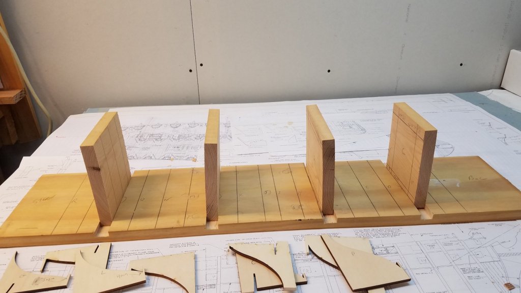
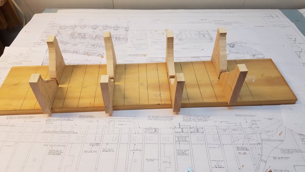
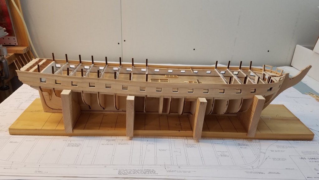
Part #2 The second jig/cradle to hold the hull. So I took another piece of pine that is longer and wider than the hull. I cut into it 4 slots about 1/4" deep. These will align with frames C, G, L. P Now I kept the plywood sheets that the model frames came in. I used that as a template for the next step I cut each frame in 1/2 and laid it out on another piece of pine. On the band saw... cut them up And after they are cleaned up Note the keel rests flat on the board. The braces are adjustable within those slots. So as I add planks.. I can slide them out to adjust to the width. Once I copper the hull. I'll add felt to the inside face of the braces to not mar the Copper. Then when model is finished... the cradle can be used if I ever have to transport it. That jig took me a whole day as well.... 🙂 Now I can get back to planking!! KMart

-
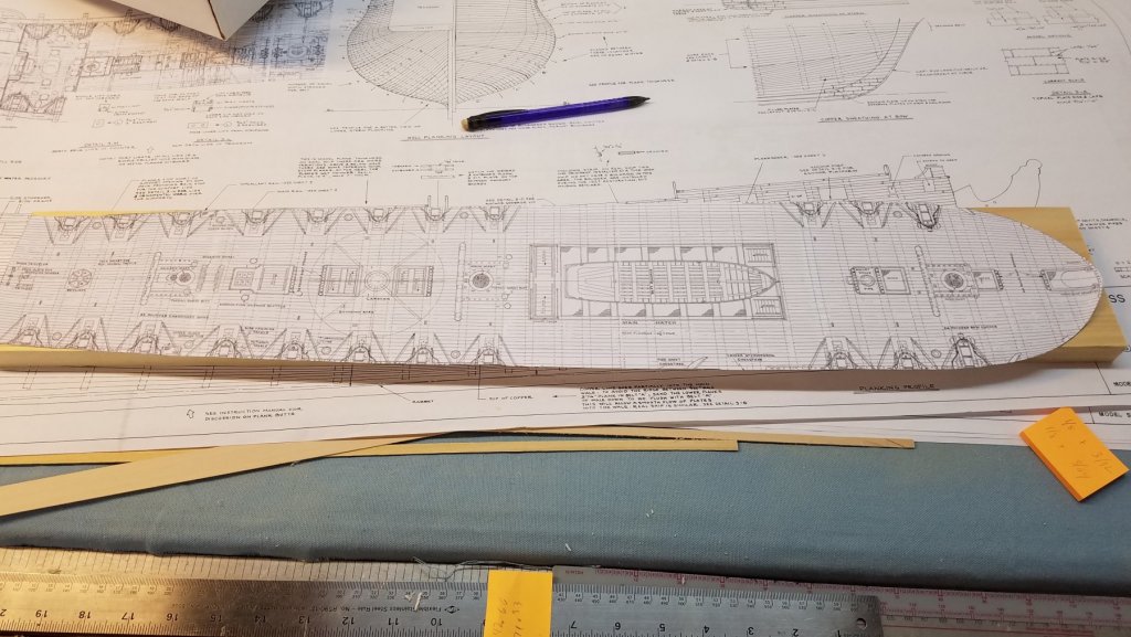
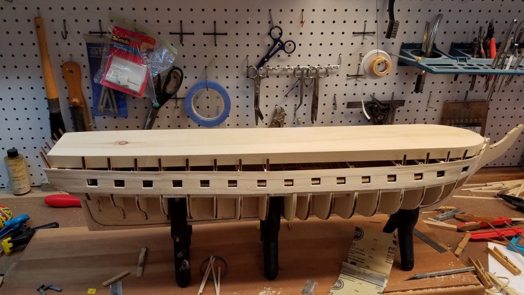
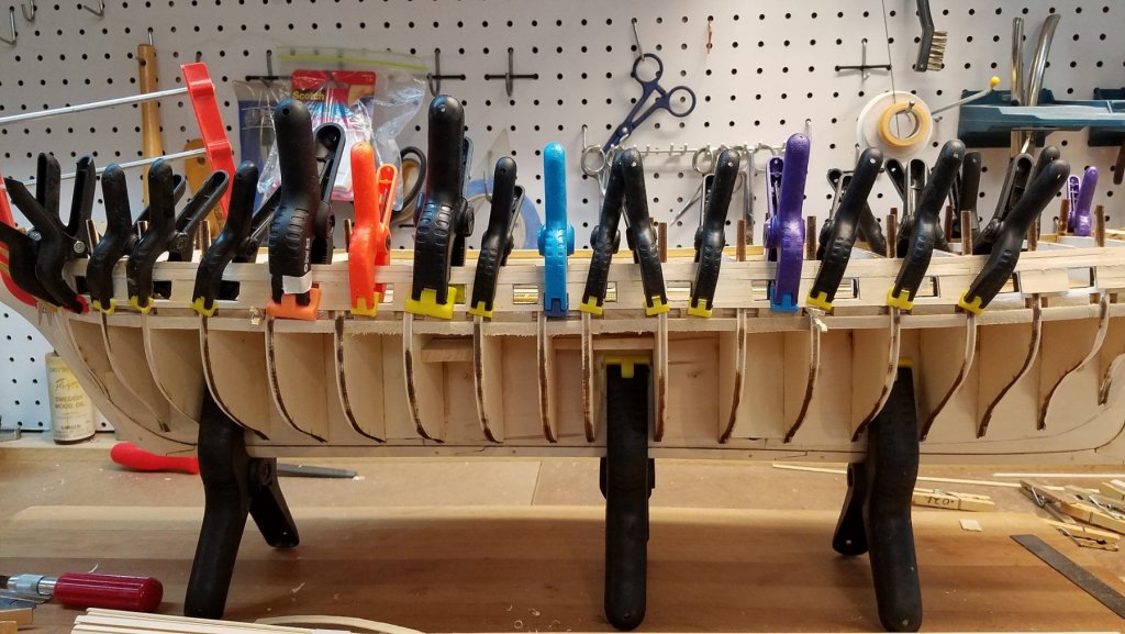
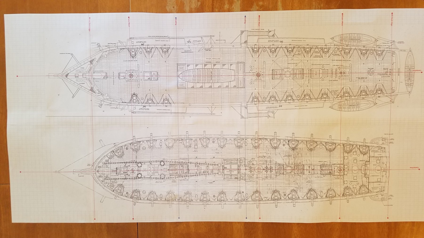
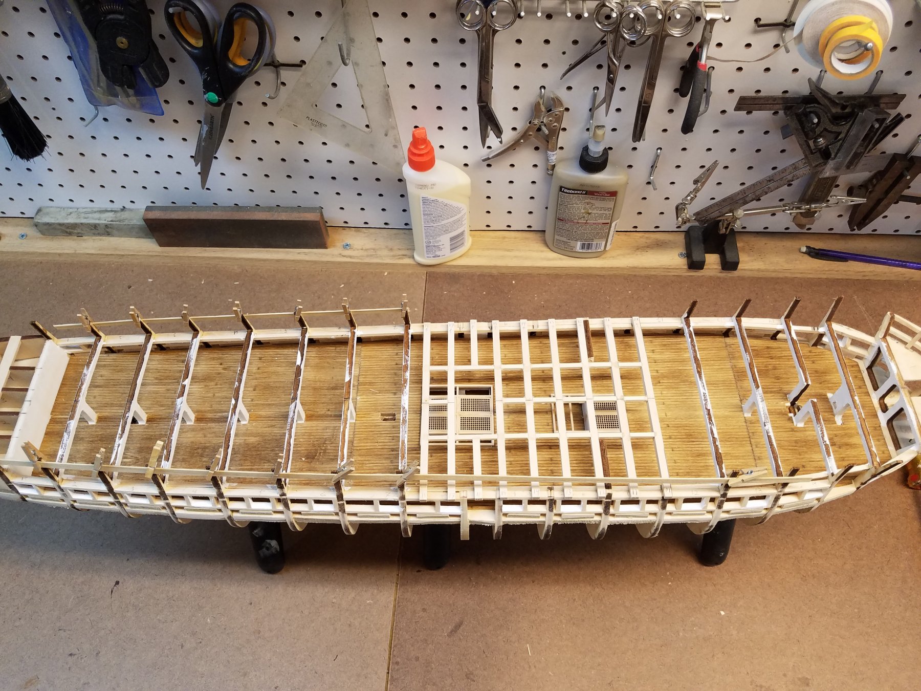
Time for an update. I haven't posted in awhile, but I have spent some time in the wood shop. Continuing planking mostly. Its a fairly slow process. I've got a bit of a rhythm down in terms of cutting , fitting and then gluing a given plank. But then I need to let it set 2+ hours. And can only do 1 plank at a time. Then alternate and do the other side. That keeps the planks from warping the frame. It also allows me to check both the bow and stern to make sure the matching planks align and have a similar run. At this point I'm my next plank will be the top plank of the wale. So a mini milestone. The wale has 7 planks each side. So getting the wale done will be my next target milestone The planking so far highlighted that before too long... I need to make some jigs to hold the hull deck down so I can plank the rest of the bottom. And then another jig /Cradle to hold the boat, once the bottom is planked. For the Jig to hold deck down Step 1) I needed a pattern of the Spar Deck Imported both the spar and gun deck blueprint pdf's from the Constitution CD into MS Visio. Note each deck is split into 2 pdf's. Deck is too long for a single page. Within Visio.. through trial an error.... aligned and stitched the two halves of each deck together. Now the fun part. Each deck spans 1 page wide by 5 pages long. So print out the deck to inkjet printer Trim the white space edges off Tape the 5 pages together Cut out the deck Test fit on both the ship and against the Model Expo 1:1 scale plans Re scale in visio Repeat steps 2-7 5 more time until I got the scale right. Repeat 1-8 again for the second deck. Ugg... I litterer spent a full day ...but the result. They match in scale with both the Expo plans and with the actual deck, So it was work it. So... Now I cut out a copy of the spar deck. Used that as a template to cut up a piece of pine I had. This rests mostly on the bow and stern pieces but I'll add some spacers so its on the deck beams as well. Now I can flip the hull over and plank the bottom.

-
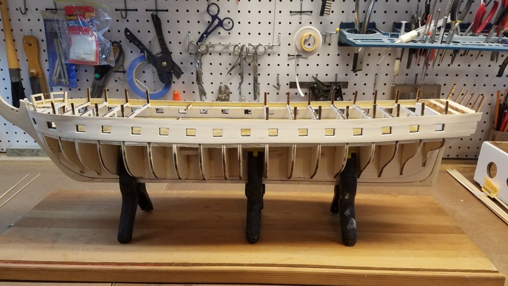
Soo , back to work. Next up. start the planking. At least the bands around the Gun Deck.... I plan to plank up to the spar deck to strengthen those very thin tops of the bulkwarks. I already broke off half of the bulk-works tops and had to re glue them back on. And then down to the first wale. At that point I'll figure a way to flip the hull and hold it upside down to do the rest of the bottom. I started with the plank right above the gun-ports. Used that gun-port spacing jig I used earlier to make sure I left 1/32 space above the gun-port. (Sorry, didn't take a picture of it in use.) but basically. put 1 plug in each gun-port all along the side. Each plug had a 1/32 strip on its top and bottom edge. Thin I just glued the 1st plank flush on the top of the jig. Not perfect but fairly close and consistent 1/32 spacing above the gun port After the first one was on. the next two were easy. Note for these planks. There is no tapering. They are full with the entire length Once above the gun-ports was done.. I had to figure out best way to keep the plank edges around the gun-ports clean, square etc. In past models, I planked right over the gun-ports and then cut the openings back out. but those were smaller scale models that didn't show the frame to support the closed lids. Originally, I planned to do the plank right below the gun-port next, using the same technique as the upper. Then plank in between the upper and lower. Looking at the plans... the height between the top and bottom gun-port (including the 1/32" edges) was consistently , 4 x 1/8" wide planks for a total width of 1/2". So I glued edge wise 2 sets of 4 planks. And then sanded them smooth. Confirmed with calipers the with was constantly 1/2" the hole length. Had to sand a bit as the glue added about 1/64" Then I measures each section between gun-ports... again allowing for 1/32 on each side. Cut the strips and glued on. Then the bottom plank just went tight against the existing ones Overall... they came out well. All the ports came our properly sized and square. The vast majority of them had a very consistent 1/32 lip on all edges, all sides. However, the first two gun-ports (from the bow) on both sides, The lower lip was closer to 1/16th" You can see it on the first gun-port. I cant figure out how that happened as the 4 planks are a consistent height. Maybe it has something to do with the curve / angle of the hull at that point? To fix, I can either add a small 1/32 high plank strip to the top of that bottom plank (for just the two ports). Or trim the actual ledge down by 1/32. The one thing I really don't like is there is a slight wave in the run of the lowest plank. You can see it right above the middle clamp. It looks exaggerated in the picture. By eye its not as obvious. but it bugs me a lot. I'm hoping I can correct with some minor splining on the next plank down. And then then with the black pain it wont be visible. That's it for now!


-
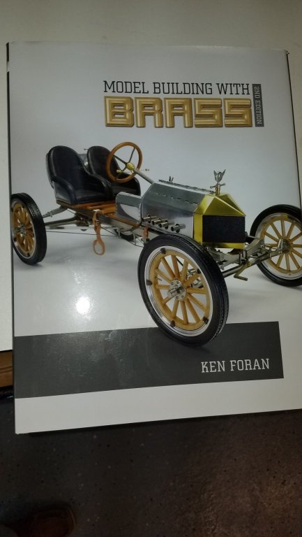
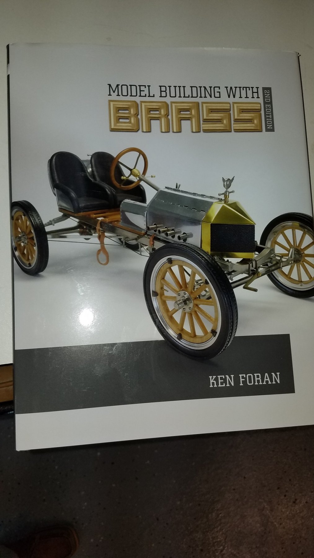
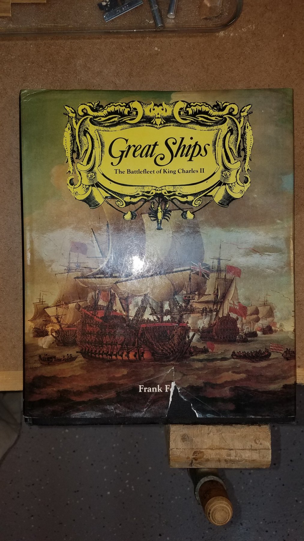
Eric Good question. I haven't really decided yet. Putting that decision off as long as I can. I'm leaning towards keeping the full 8 beams just because I like the look. But I also realize its not accurate as the 1812 version. So there's my dilemma. In the mean time... Christmas came in Oct. Got two new Books. Kens... Just looking through it.... WOW. just unbelievable craftsmanship. It will inspire me to do a lot more metalwork on my Connie than I intended! I Highly recommend the book to any ship modelers. I have to say it again WOW! Second Book I had on my watch list. Normally a Very expensive book, (> $300 Yikes!) but I saw great deal on a used copy on Amazon ($50) so I grabbed it. Not so helpfully on to Connie. but will be invaluable on my next ship post Connie. I have Euromodels Royal William sitting on my shelf for retirement. But that a Looong way off. 10 years. Besides it will take me that long to finish Connie 🙂

-
Wow Popeye, That paddle wheel turned out Awesome.!!!
-
Looking Good Jon! I really like how your gratings/gangways to the lower deck turned out. Q? The green paint? Which did you use? The model shipway's paint or something else? I just picked up a bottle of Craftsmart acrylic paint from Michael's. "Grass Green" (mat). Looks really close to the right shade of green.
-
Cpt Steve. I'm bummed youre scuttling your Connie. Enjoyed your log todate. Will be watching and pull up a chair for your next build log. Curious to see what ship you choose next. Kmart
-
Hello All, Sooo I've been out of the workshop all during the Northeast Sailing season (May-Sept). Just put the real sailboat away this past weekend. (Depressing) But now I'm eager/excited to get back into the wood shop and pick up where I left off on the Connie. Just ordered xKen's new book "Modeling in Brass". I'm sure that will come in very handy. Should have it in hand in a few days. And catching up on some of the great Connie logs I've been following to get inspired! (JSGersion, UsedToSail, Capt Steve, XKen.....and many others!) So hopefully I'll have some new posts, updates, pictures and questions for everyone over the next few weeks! Best K
-
xKen, You wrote a book?? I missed that. Whats the title so I can look it up on Amazon??
-
Used2Sail. Again, your work is stunning. I keep looking at your log and hoping my build come out half as good as yours 'Ill be very happy! K
- 1,348 replies
-
- 3
-
-
- constitution
- model shipways
- (and 1 more)
-
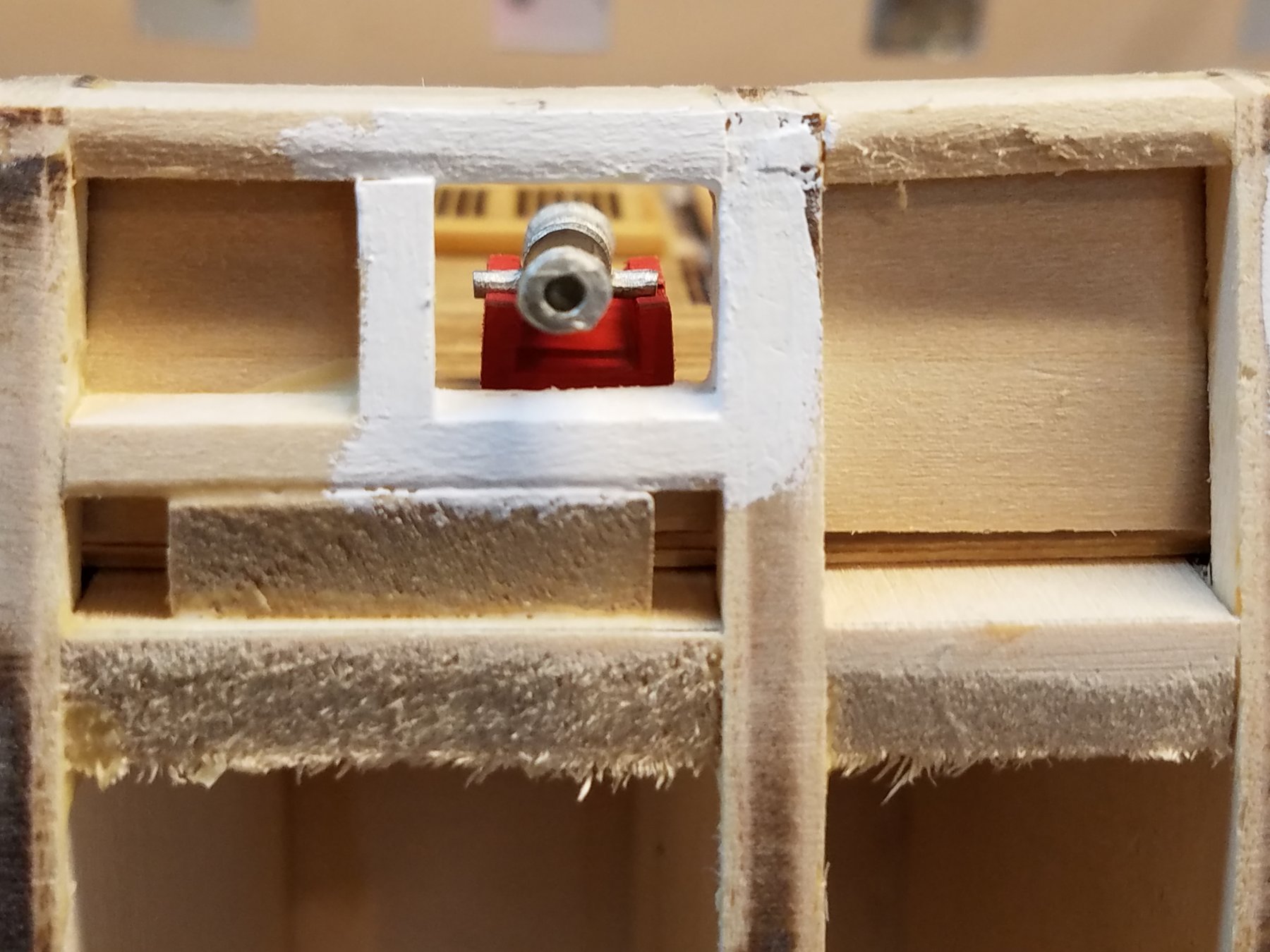
Jon, Looking good. I like the green plank on inside of bulwarks. Glad to see someone following my build and benefiting from it. :-) It's mutual as I keep checking you log for ideas as well! From you pic.. you gun barrel does seem to be too low thought. Hard to be sure until the top gunport sill is in. (See if its centered) I know the spacer under my gun carriage was taller than i expected to get the height of the barrel right. I think used2sail did some surgery on his carriages as well to increase the height. Best K
-
I also, spent some time this weekend painting... in prep for planking the topsides of the hull. gunports.... White stripe (Including the ledge/lip that supports the gun ports. But black sills. As my painting is not very good. How do I paint those black silts on white and not muck it up? Not easy. I took the approach to paint them white first. (Yes I did paint the gun carriage red to see how it looks. Not bad :-) Then I painted the black sils Not Bad. Even the inside came out respectable. Will still need some touch ups later.. But I could've done much worse. Now I'm almost ready to lay the hull planks starting with the ones right above and right below the gun-ports. There needs to be a 1/32" lip around the frames when installing the planks... (This is to support the gun covers when closed. So I need a jig. I took the jig I used when I first framed out the gun ports to keep them the correct and consistent shape/size. And cut them into 14 individual pieces. 1 for each gun port. I then glued a 1/32" thick strip on the top and bottom. Next weekend, when I go to add those first two planks... I'll put one jig in each of the gun ports. Lay the plank to rest tight against all 14 of those jigs against those 1/32" in strips.. And I should get the perfect spacing between the top and bottom of the gun ports and the planking. I'll then use same technique for the spacing on the sides . That's the plan anyways. Till next time K


-
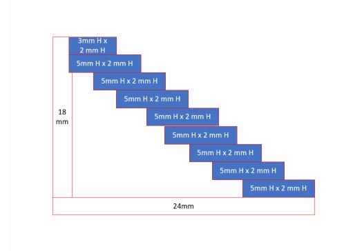
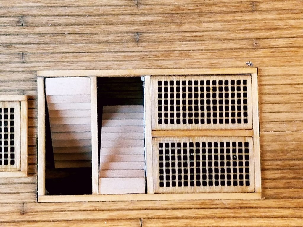
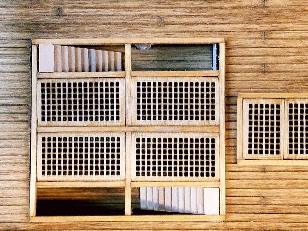
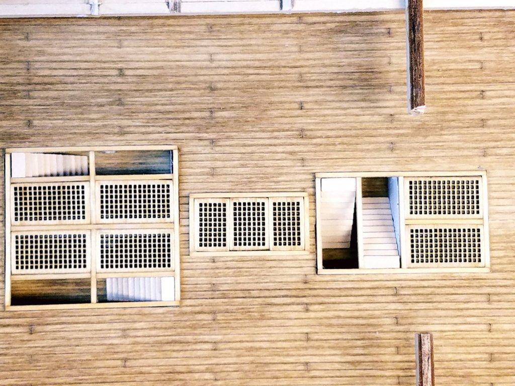
So this week worked on the stairs going from gun deck down to berth deck Did some measuring and decided the size stairs needed to be. I don't know if these sizes are to scale, but they fit the space and "look" right by my eye. 18mm high 24 mm long at the base 2 mm treads 2mm hieght of each step 9 steps per flight. To make the steps I took 2 strips of basswood. 5mm x 2mm by 24" I glued them together lengthwise. with a 3mm overlap. (That leaves me the 2mm tread) Once glue dried... I cut it in half and glued those two together again 3 mm overlap. Repeated process 2 more time.. so I had 12 steps. Cut off the extra steps, and cut to width. 4 sets are 8mm wide and 2 are 12mm wide. Cleaned them up and just set in place, Note stairs and are not glued in yet. Soo. plans show 4 stairs going down. with the other two mirroring the ones above. I cant see how that would work in real life. The bottom steps would almost touch?? I think I'm going to leave it configured as above with only the 4 total. leaving out 2 stairs. Overall.. I think they came out acceptable. I'll stain them add some rope handrails and glue everything down next session. Oh.. And a preview what they look like when the spar deck gratings in. There will be 4 more stairs that go from the spar deck down to the gun deck. one at each corner of the open gratings.

-
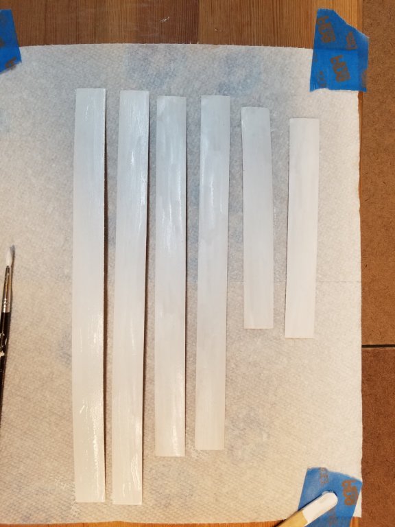
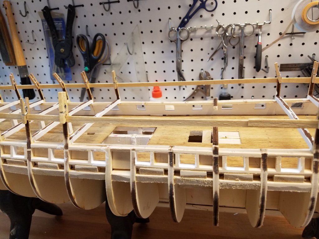
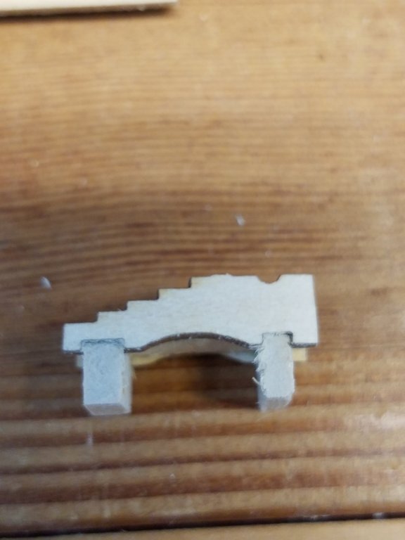
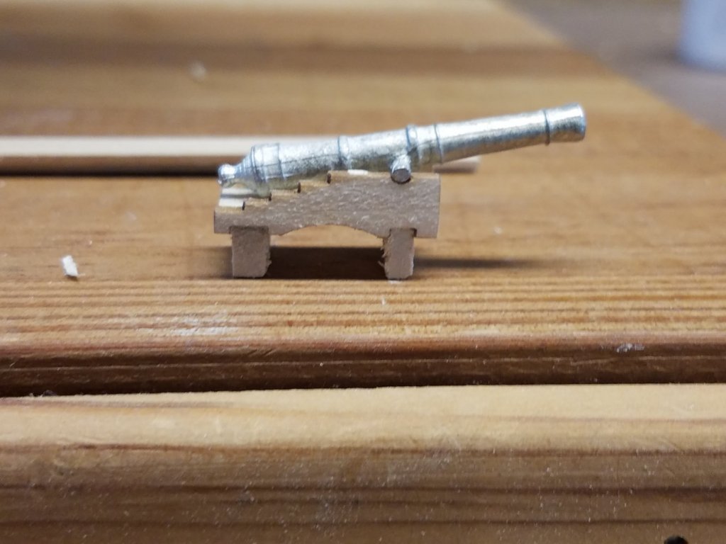
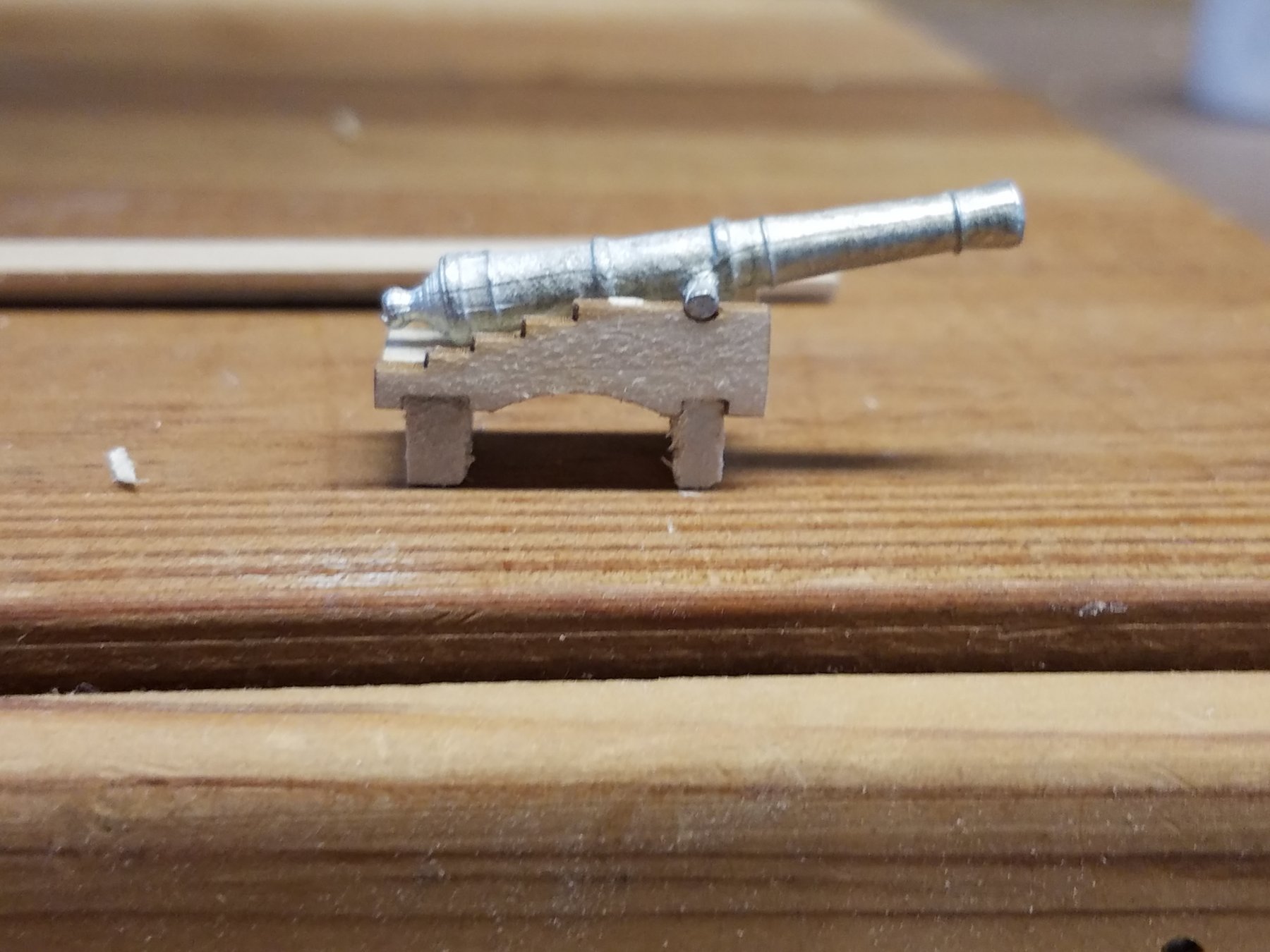
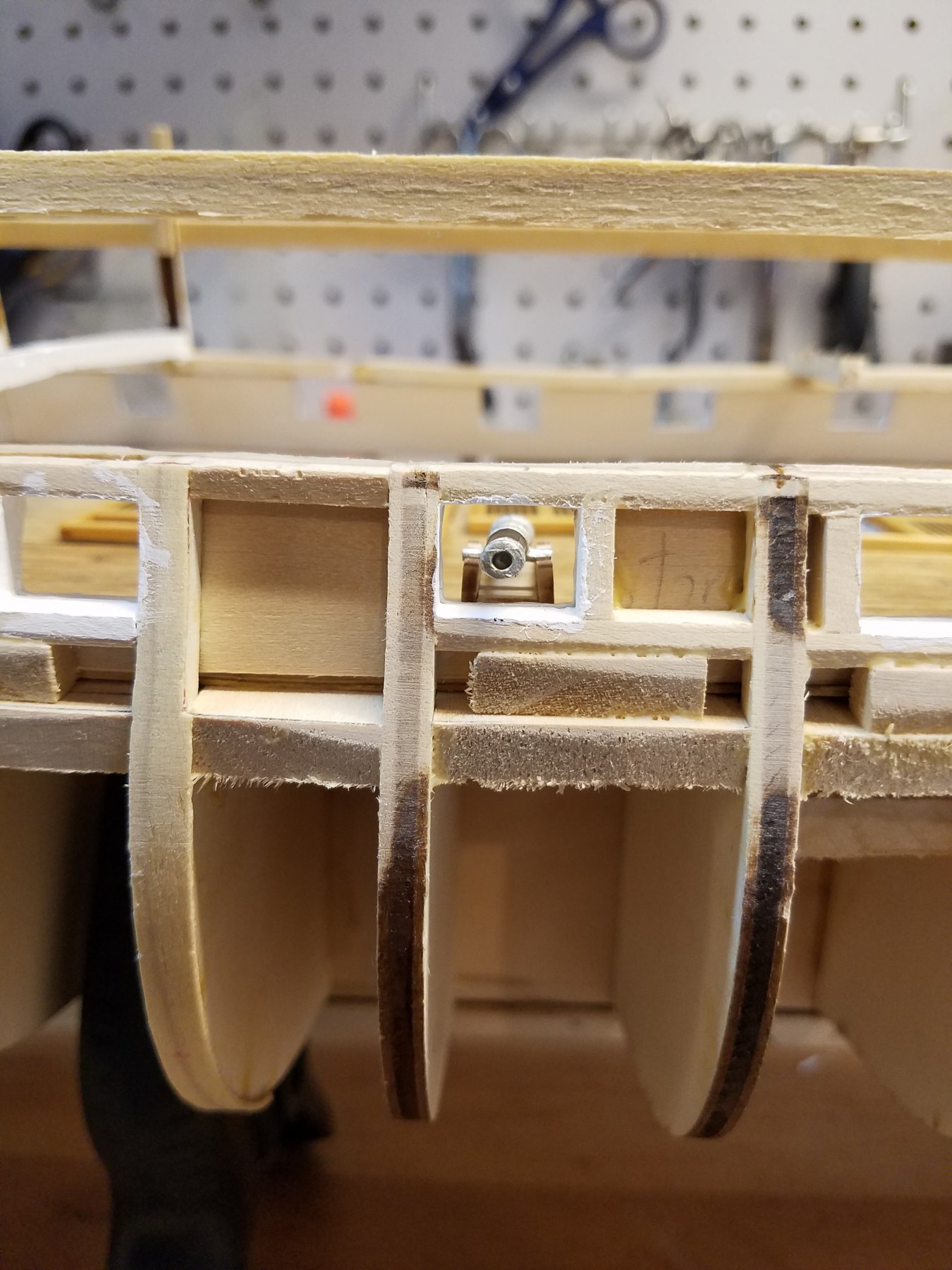
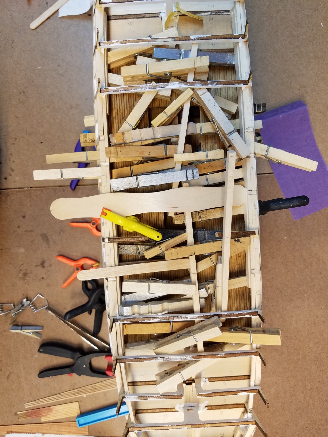
Next up... planking the Gun deck bulkwarks... Sorta. So they should be planked... but considering 1) They will barely be able seen when looking through the gun ports. And then in low light after the spar deck is in place 2) With the Spar deck beam there...its practically impossible for me to do a decent job planking and getting them to come out well. Let alone sand or smooth them after installed. Not with my fat fingers. Soo after pondering it a bit. I cam up with an alternate approach to planking. First, I took some basswood stock and made some sawdust on the mini table saw. After a bit of practice, I was able to rip some pieces that are 1/32 thick. I further cut these to 18mm wide strips Sanded them down, cleaned them up And primed and then painted them bulwarks white! Added glue and preceded to glue them in as the bulwarks planking. Sorry, didn't take any pictures of the assembly part. But lots of clothespins were involved.. and some swearing! After all glued. I cut out the gun-ports and touched up the paint Obviously , they don't looked "planked" but once spar deck is on, you wouldn't be able to see that level of detail anyhow. Overall I'm happy how it came out. So next. test fit a gun I assembled 1 cannon to see how it would fit From experience I know that the trucks (wheels) alone don't provide enough surface area to keep the cannon in place once glued. Especially when they inevitably get bumped during construction. My plan was to add a piece of wood under the carriage the same height as the wheels. But while assembling the test cannon and struggling the best way to make the axles.. I got an idea. Replace axles with the piece of wood of the right height. Even better, I can mass produce these easily to ensure all the cannons are at the same consistent height. And as a bonus, it makes assembling the carriage a bit easier. (The two pieces when put in the notches.. hold the pieces and provide a surface for the carriage floor to rest at the right height when gluing up) Does that makes sense? Now this looks ugly and unrealistic. Accept I'll glue the actual carriage wheels to the ends, and they will become invisible at that point! At least that's the theory! This also just looks wrong! At least it came out at the right height. Looks centered in the gun-port. I'll clean up the one. paint it all up , add the wheels. If it works, looks acceptable.. then I'll repeat 29 more times. :-) Otherwise it will be back to the drawing board. Now with the inner planking is done...I'm getting close (and eager) to adding some planking on the outside. Still need to paint the gun-port sills black first. That will have to wait for the next session!
-
Keep at it. Its an interesting model and displays great when done. Even those not intetested in model ships are facinated looking in. Jeffs log wad a great resourse to me as well. You cam check out my log as well. K
-
J Amazing detail you put into the Stern cabin! Great idea with scaling the gun deck plans to locate the deck fittings! Wish I though of that! I Spent hours trying to scale those gratings and stairs from the restoration plan. BTW do you know how what % you had to scale the gun deck plan to match the model scale? I'm following you closely to see what detail u put on the gun deck.. (so I can copy :-). After see how you cut out ALL the spar deck beams to get to the gun deck... I'm thinking I did it the hard way trying to work under them! K
-
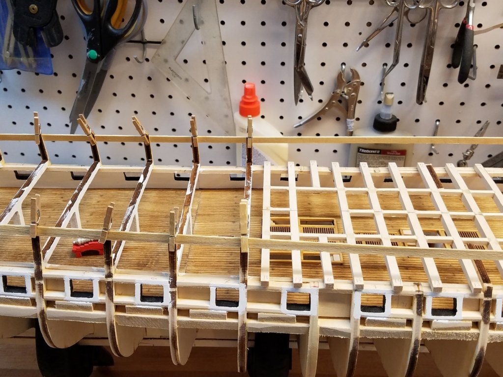
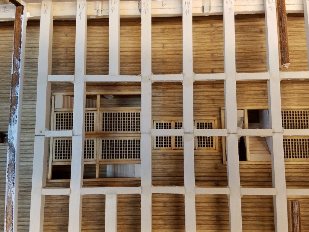
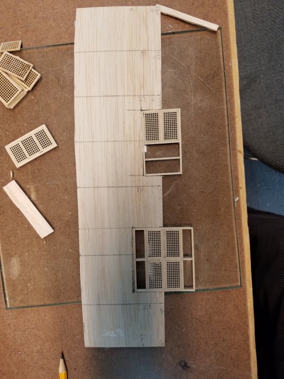
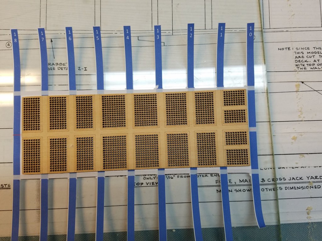
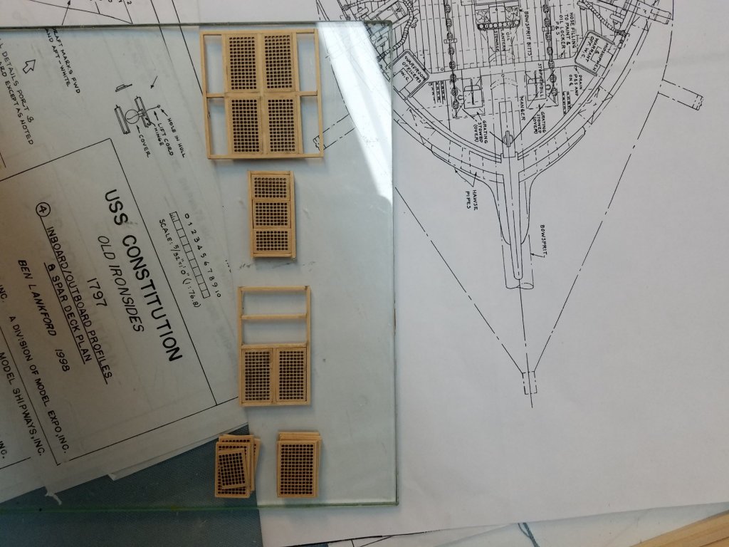
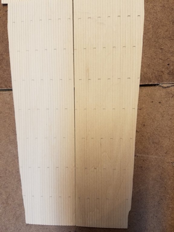
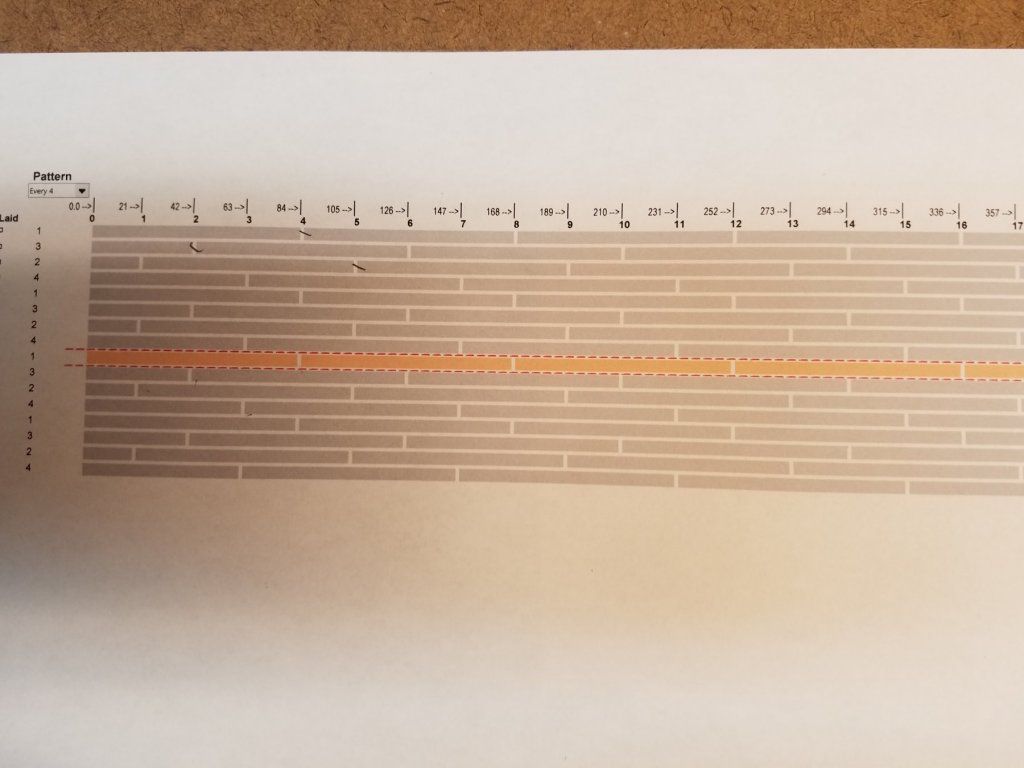
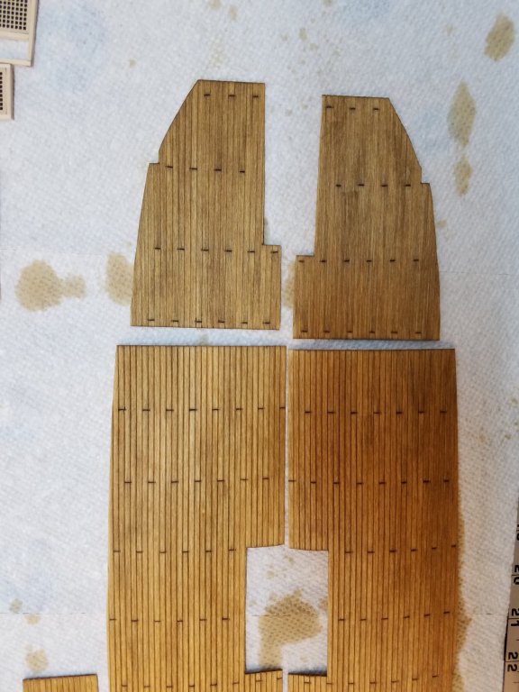
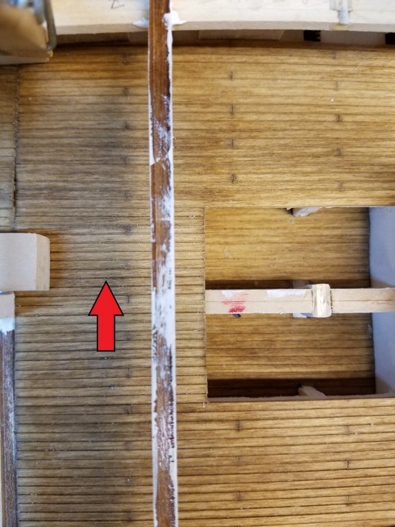
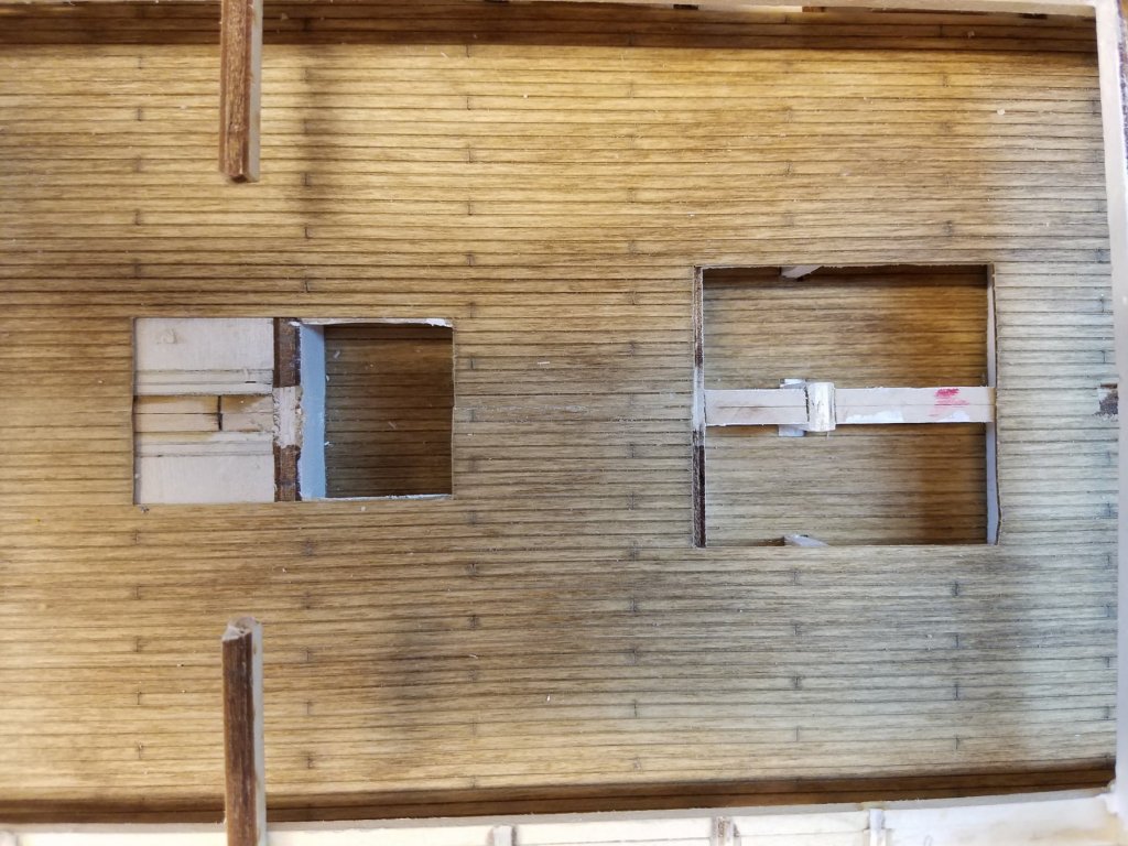
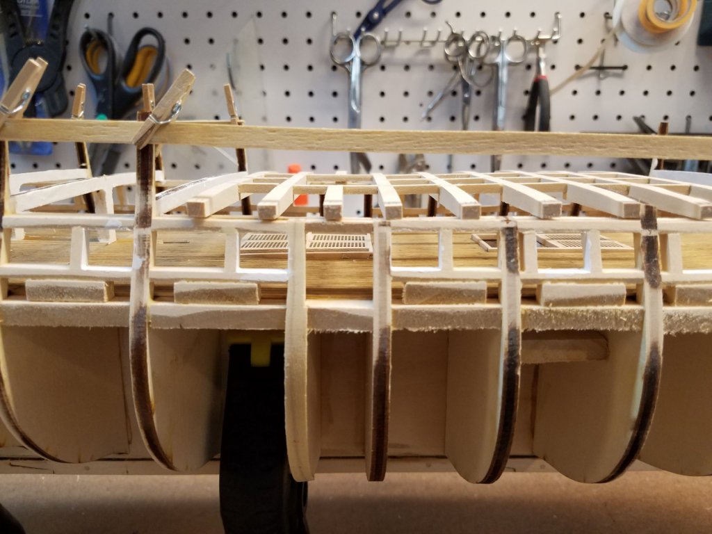
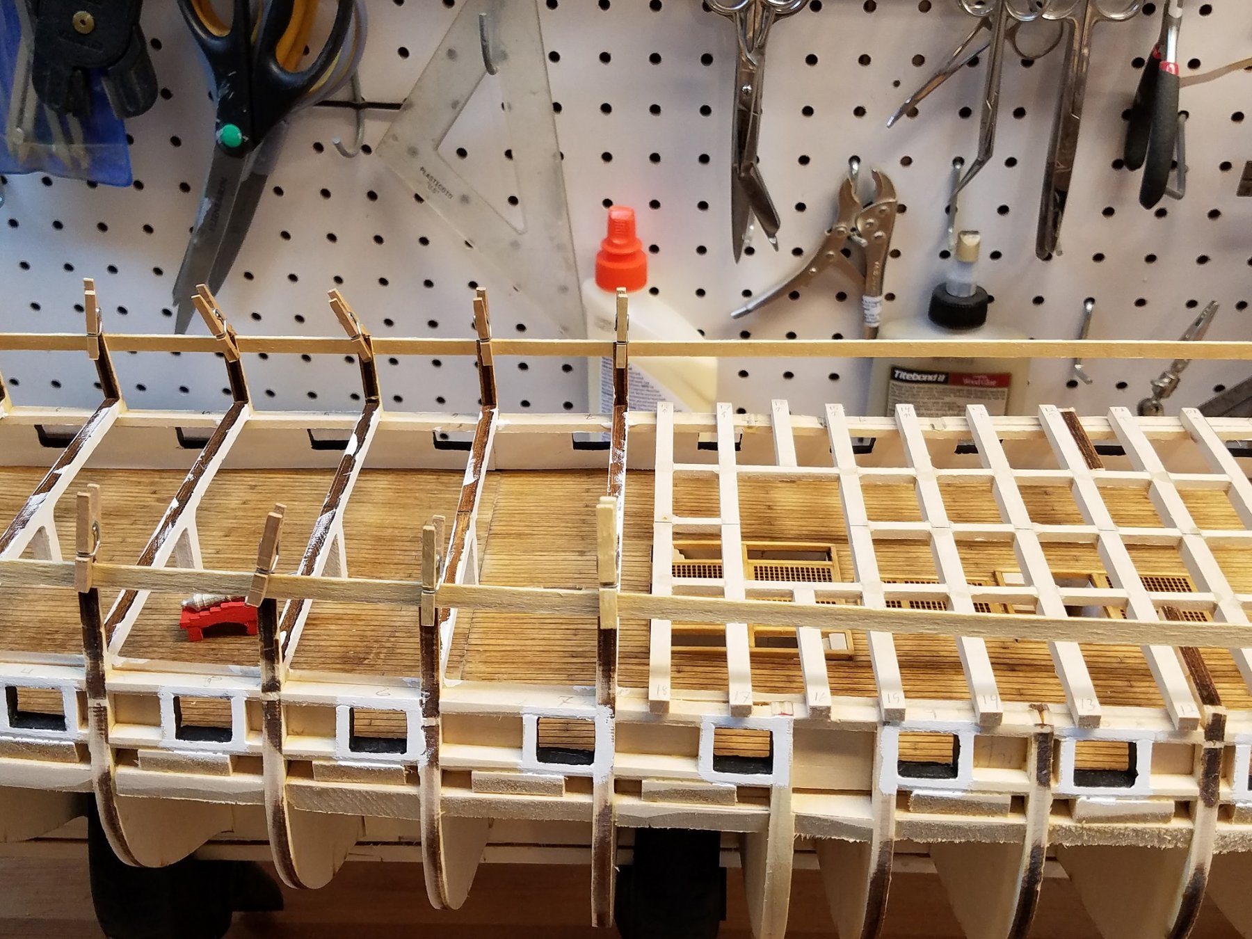
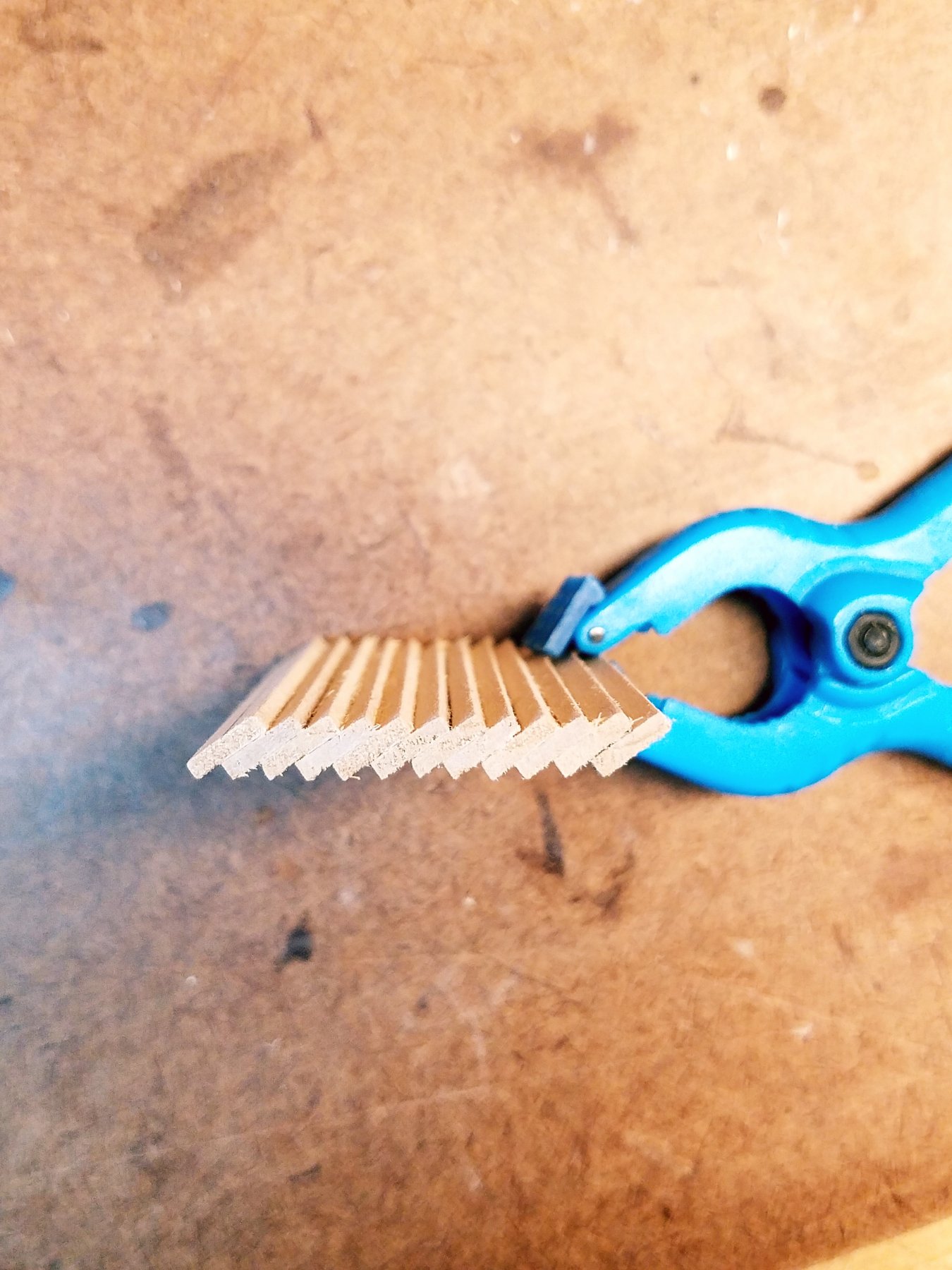
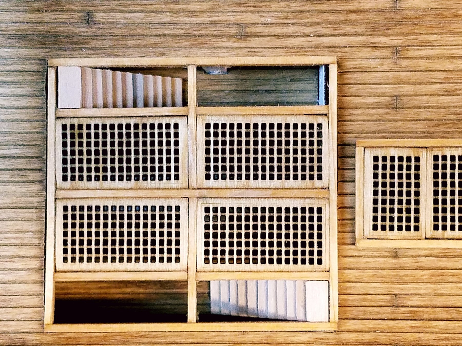
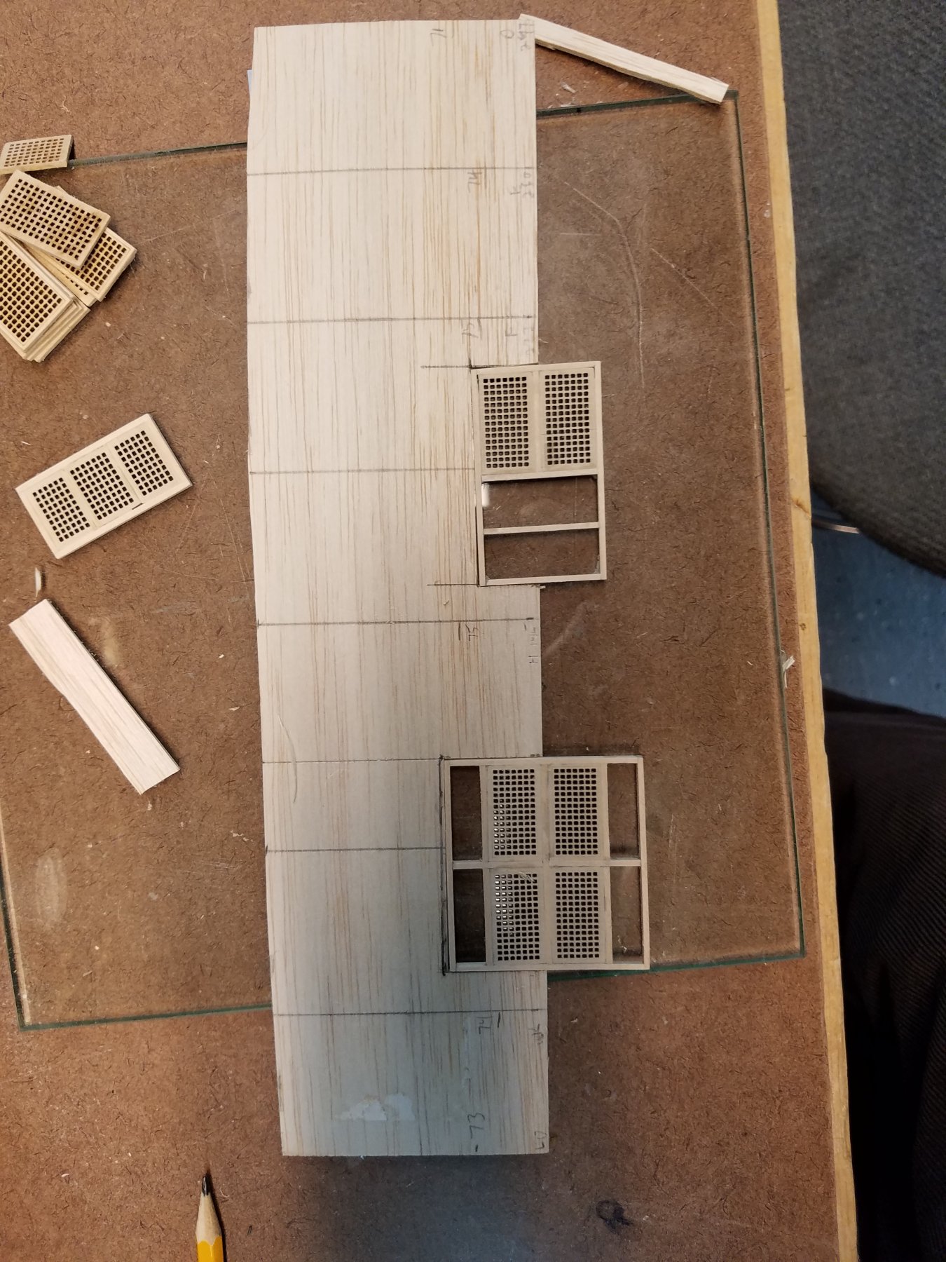
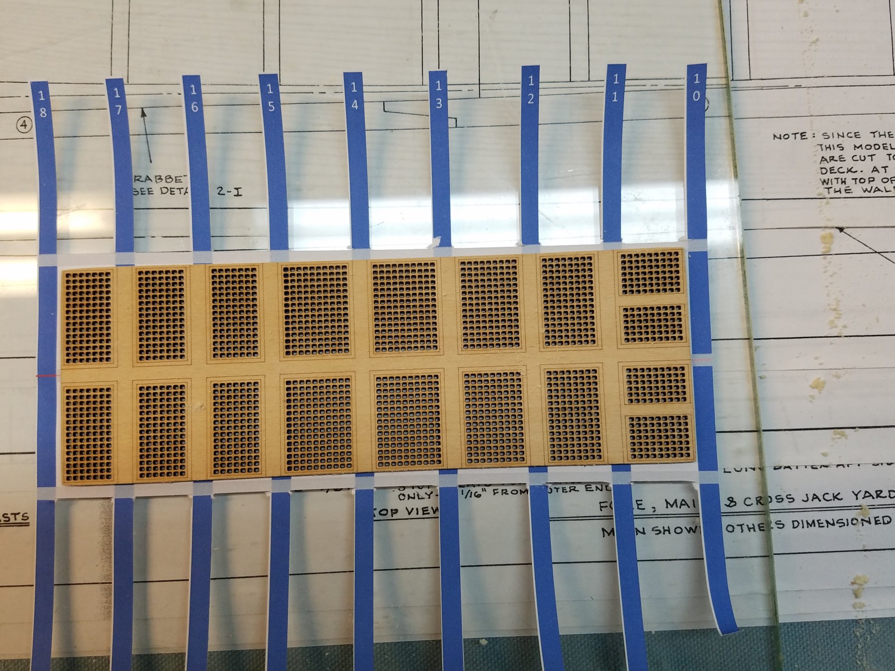
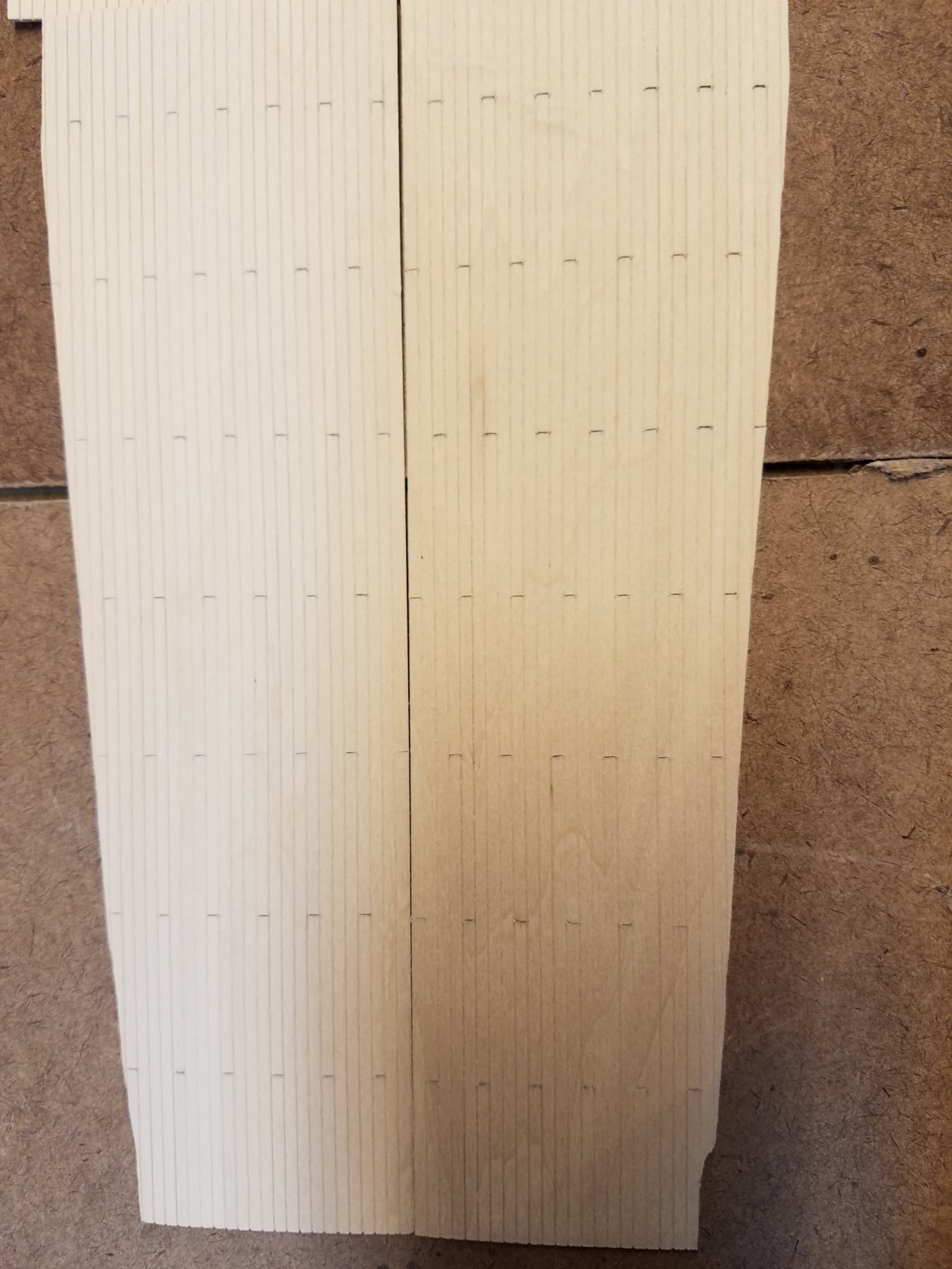
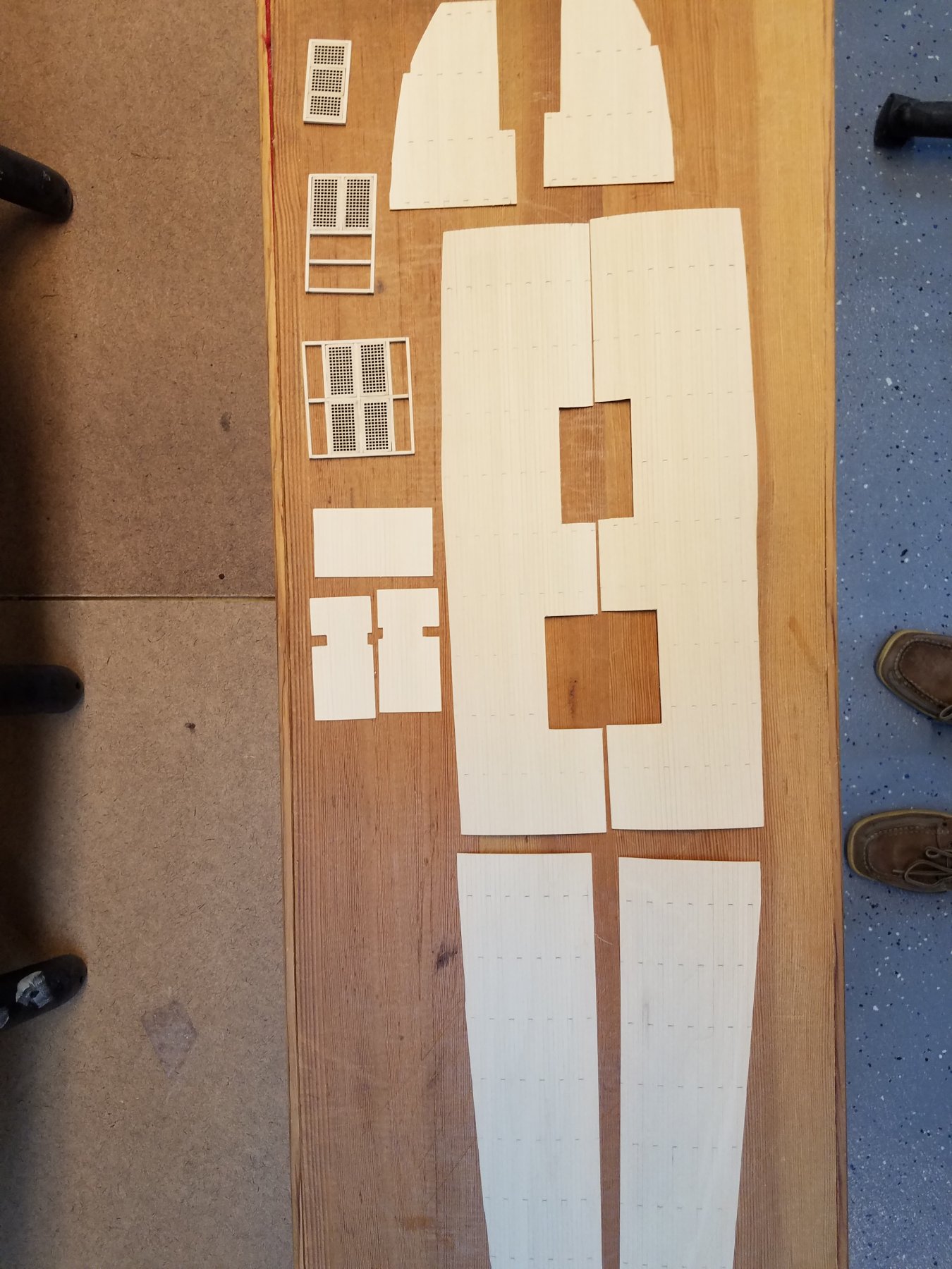
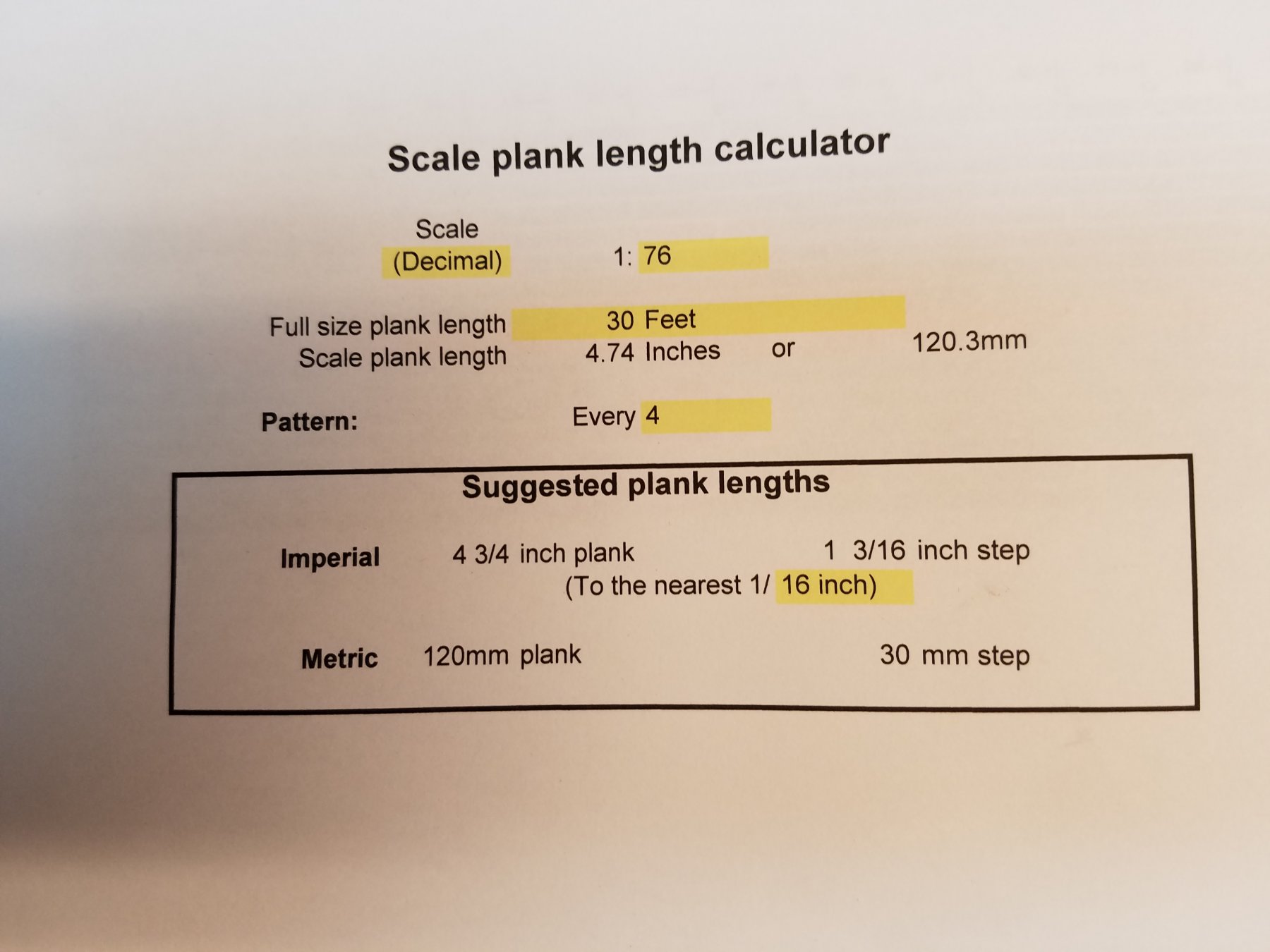
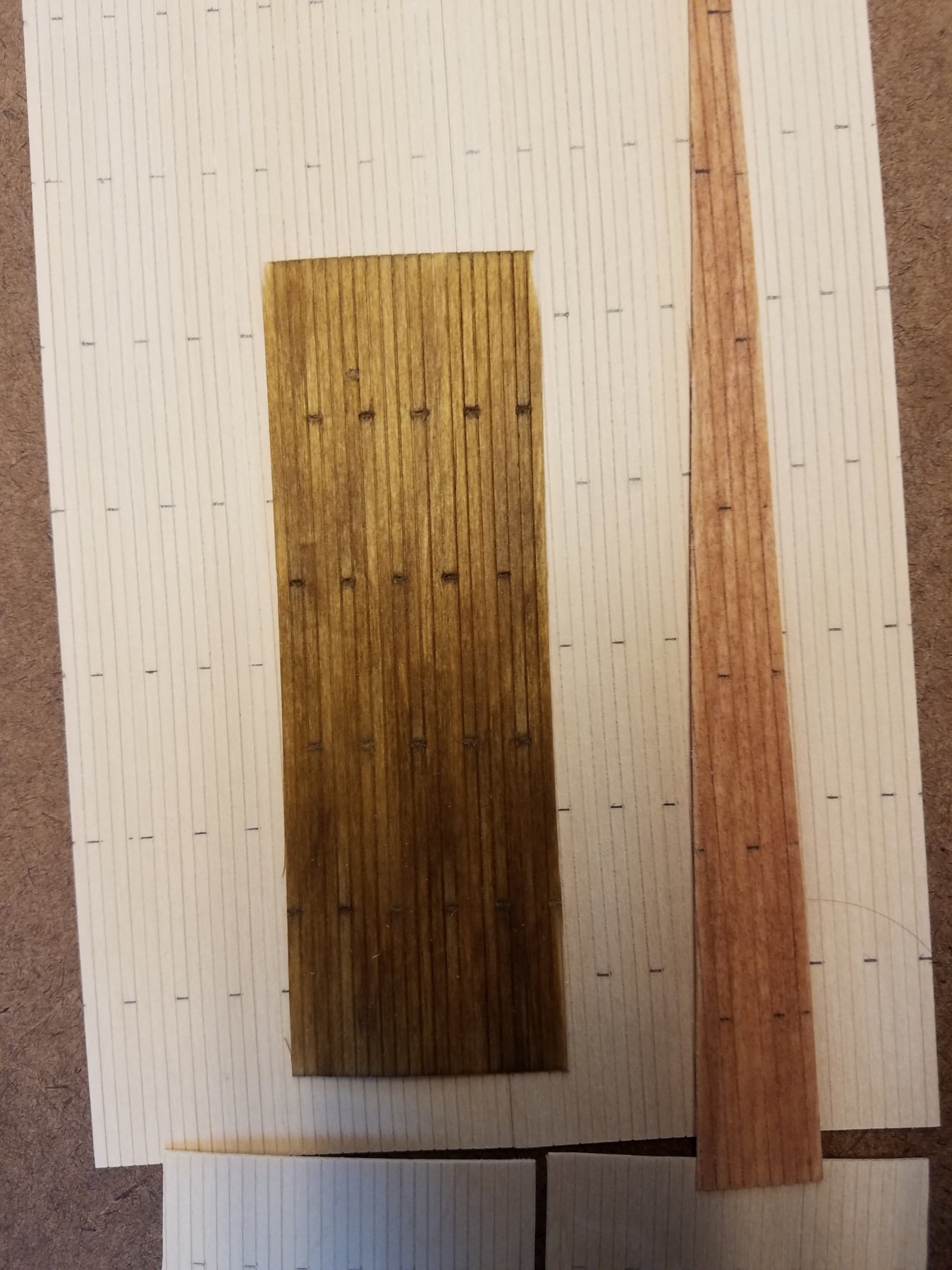
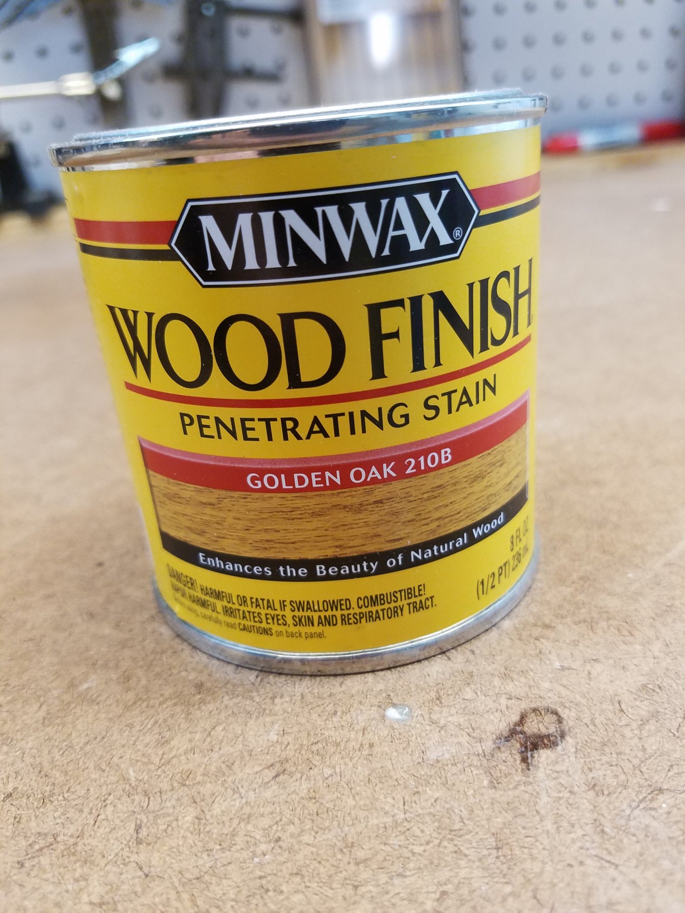
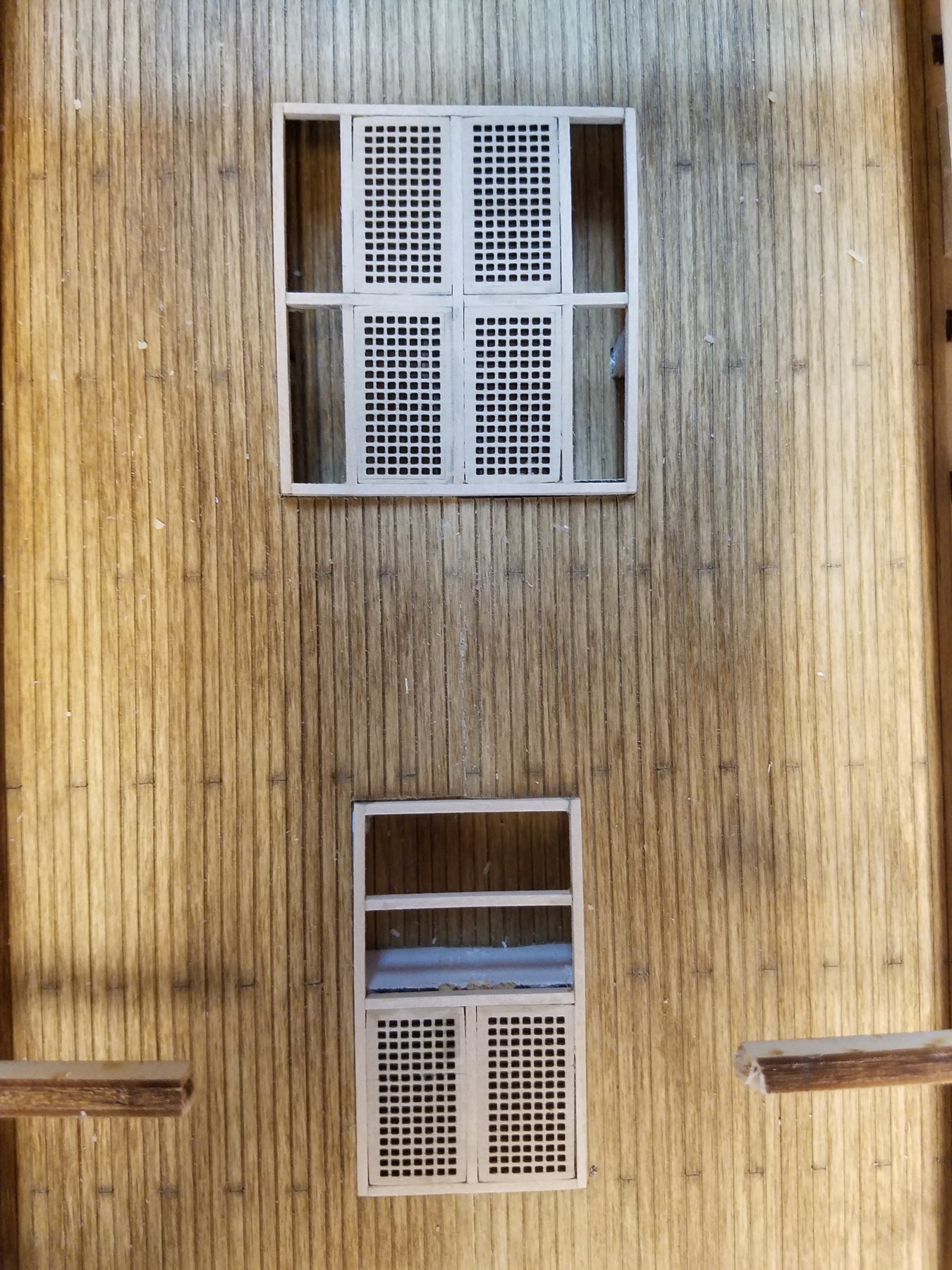
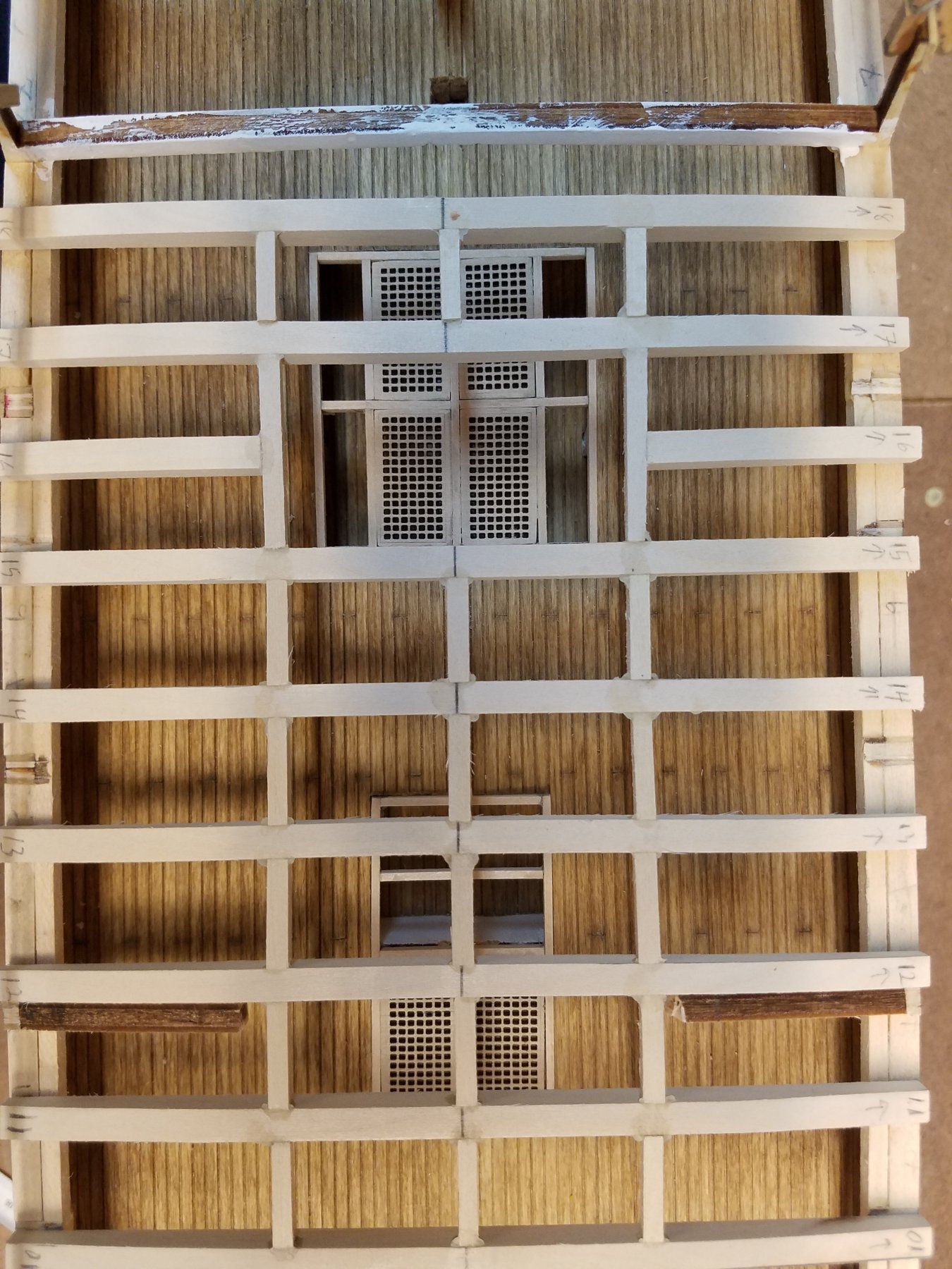
And now back to modeling my gun deck. When I last left off... Had the gun deck sub floor in, and had cut away a section for where several stairs and gratings will go to the next level down. created templates for the gun deck floor. Also started making the gratings For the grating, as I don't need gratings that came with the kit for the Spar deck... I cut them up into individual gratings, and used them on the gun deck. This is what I cut up into individual pieces I sized my gratings to make best use of these smaller pieces and tried match the grating pattern/layout on the CD restoration plans The circled is what I'll put in with 4 stairs ( 2 up to Spar and 2 down to Berth Deck) in the main hatch and the 2 stairs running athwart ship in the forward section The gun deck floor. At first I going to try and plank it with some 1/32 thickness by 5 mm wide strip wood I have in my stash from prior models. BUT.. while in my local hobby shop... (in the wood section of course... ) what did I find, but pre scored planking.. 1/32" thick with the plank scoring at 3/32" And by chance, the planks on the model need to be 3/32" wide. What a find. Next I used the template to cut pieces of that into the right shapes While the planks are scored. the plank ends are not. So I needed to scribe those ine in. I used the planking XLS calculator from this site. Went with a 4 butt shift and 30 ft planks. That gave me 30mm long planks So following the template, I drew the but ends on the sheets with a sharp pencil. Then I scored each line with a sharp exacto knife. After that I lightly sanded the surface. It didn't remove the entire pencil line, but it made it much less noticeable. I then vacuumed the sheets to get all the sanding dust off. For the color, I'm using minwax stains. Tested a few shades. You can see how the but ends came out. The pencil mark still visible, but the stain seeped into the scoring.. it also pooled in the gaps between the planks , leaving a nice simulation of the caulking. t I went with Golden Oak Next step was to glue them onto the model. Because they are thin sheets, after applying glue, they wanted to warp. So on the fly, while the glue was setting, I needed to find a way to hold them down in place....... Clothespins work in an emergency Now this picture I show ..because something is missing. I forgot to account for . Do you see what it is???? Give up? The hole where the main mast tenon rests! I forgot to cut that in. After carefull measuring, I found the spot and cut it back in. Whew! glad I caught that now and not later or it would have been a real problem. note, I think the camera flash highlights the pattern in the grain that looks terrible in the pic below. But by eye in normal light. it looks good! coloring is uniform light golden color. more like midship. And a closeup with the deck beams. you can see how the openings align with the gratings and openings on the Gun deck. Also, the plank caulking and butt ends look better in this pic And you can start to visualize if you are looking in through gun-port, you can see the deck in there. So that it for now. Next up, I'll paint the gun frames black. Then put the inner planking on the walls of the gun deck, Then outer planking (again just the band on the gun deck.)


.thumb.jpg.fb5d3b9e8fdc0ee6630b96ad7eb1e38b.jpg)


.jpg.362505c9d1d9243c9b6bb2c5886b8f8c.jpg)