HOLIDAY DONATION DRIVE - SUPPORT MSW - DO YOUR PART TO KEEP THIS GREAT FORUM GOING! (89 donations so far out of 49,000 members - C'mon guys!)
×


tkay11
-
Posts
1,829 -
Joined
-
Last visited
Content Type
Profiles
Forums
Gallery
Events
Everything posted by tkay11
-
The cheapest piece of boxwood that I have found in the UK is from old boxwood rules/rulers that you can find on eBay. The cheapest old ones (generally labelled 'vintage') go for about £3.50 inc p&p for a 3 foot folding rule and slightly less for the 2ft versions -- although you have to be patient and keep a good eye out for them at this price. Occasionally a brand new version crops up even cheaper when the seller is not aware how much more they can get if they brand their rule as 'vintage' -- I bought a new unopened 3ft boxwood rule for £2.70 inc p&p from eBay in January. You have to search both 'rule' and 'ruler'. This means longer sets of results than if you combine with 'boxwood', but you then catch the sellers that omit the word. I had a search follower set up on eBay that would email me whenever new rulers came up for auction. That way you don't have to keep searching yourself. These rulers are a good size (about 4.6mm x 25mm) for such small blocks and you can make enough for several models out of even a 2ft rule. It is also useful for making deck fittings and other small pieces such as boom crutches, cannon barrels, cleats etc. An advantage of the rulers is that they are made from pure boxwood which has no defects and is not going to warp. I've also bought a 1ft 2"x2" length of Castello Boxwood from Exotic Hardwoods UK (http://www.exotichardwoodsukltd.com) for £7.50. They also do nice pear cuts. Their postage was £6.50 for that as well as two 2ft x 2" x 2" pieces of pear. These pieces were only lumber cut, not milled, so I have had to finish them myself. I have yet to try the Castello Boxwood for making blocks, but I am told its qualities are very similar to boxwood. You can get milled strips of boxwood at a very reasonable price (especially as the Euro is now so low against the pound) from Arkowood online shop in Germany. You can see an example at http://www.arkowood-shop.de/product_info.php?info=p4763_holzbrettchen-buchsbaum-8-x-50-x-500-mm.html for €16.50 for a 8mm x 50mm x 500mm of boxwood. Their shipping to the UK is a standard €16.50, so it helps to buy as many strips as possible to make it more economical. They also sell milled castello boxwood and pear. Tony
-
 Wonderful to watch another build by you, Gregor. I am intrigued by the laser cutting process, but especially by the deck. It looks as though you have used the service to inscribe all the planking and other deck details. Is this correct? If so, are there special instructions for the cutters to burn only a fraction of a millimetre into the deck for those details? Excuse my ignorance about laser cutting, but looks so useful that I thought it would be nice to find out. Tony
 -
That's a really good link, Mark (SJSoane). Thanks. The editor at the Cambridge University Press told me all the 4 volumes are print on demand. Tony
-
That really is impressive and beautiful. Thanks very much, Joel, for sharing this. Tony
-
Thanks, Phil. That is very helpful indeed. Unfortunately the NRG website does not seem to have the article in question -- the CD sets go only as far as Volume 50, and a search on Maloney and also on "Steel Examined" failed to produce any results. However, what you have said is sufficient to put me off the Gill edition. Sim Comfort's edition is £400, so well out of my range. I rang the Cambridge University Press this morning and spoke to the editor of the series. She told me that the 4 volume set is a facsimile of the 1800 edition held in the university library, without any additions or commentary. You can see the 4 volumes at Volume 1. The Art of Making Masts, Yards, Gaffs, Booms, Blocks, and Oars £15.99 http://www.cambridge.org/gb/academic/subjects/history/military-history/elements-and-practice-rigging-seamanship-and-naval-tactics-volume-1 The Elements and Practice of Rigging, Seamanship, and Naval Tactics £17.99 Volume 2. The Art of Sail-Making http://www.cambridge.org/gb/academic/subjects/history/military-history/elements-and-practice-rigging-seamanship-and-naval-tactics-volume-2 The Elements and Practice of Rigging, Seamanship, and Naval Tactics £18.99 Volume 3. The Art of Rigging http://www.cambridge.org/gb/academic/subjects/history/military-history/elements-and-practice-rigging-seamanship-and-naval-tactics-volume-3 The Elements and Practice of Rigging, Seamanship, and Naval Tactics £27.99 Volume 4 , Theory and Practice of Seamanship and Naval Tactics http://www.cambridge.org/gb/academic/subjects/history/military-history/elements-and-practice-rigging-seamanship-and-naval-tactics-volume-4?format=PB They sell the combined 4 volumes for £77. These titles are pring on demand, and take 3 days to print out. They are available through booksellers, Amazon and direct from their press. I have ordered the first three volumes and will post a review once I have them. Thanks again both Mark and Phil for helping out! Tony
-
Thanks, Mark. I have already seen that site, and, having read through it, could only find references to lengths and quantities of the main ropes under 'Rigging Vol I' and 'Progressive method of rigging ships'. I therefore assumed that the version on the web is some kind of cut-down version even though it says it is complete, and that more tables might be in the original. But if that is all there is to it I would hope that the 'Elements of Mastmaking, Sailmaking and Rigging' might provide more detailed information about the structure, diameter and finishing of each of the main ropes on different types of ship of the 18th Century. I hope I haven't missed something obvious on the web edition! Tony
-
I am interested in buying one of Steel's books on rigging. I note there are two main current available titles. One is David Steel's "ELEMENTS OF MASTMAKING, SAILMAKING AND RIGGING" edited by Claude S. Gill which is the 1794 edition with five very large pocketed plates, published by Goodchild in a single volume which I can get for about £26. The other is a 4-volume set published by Cambridge Library Collection which has the overall title "The Elements and Practice of Rigging, Seamanship, and Naval Tactics" and states it is the 1800 edition. I am mainly interested in volumes 1 and 3 of this set (Making masts, Art of rigging), and the price of these two combined would be just a little more at £35. My question is whether one of these publications is better than the other in terms of size, readability etc. It seems that the Goodchild edition is not facsimile but re-set in modern type, but I am not sure about the Cambridge edition and would welcome any comments from members who have seen either or both of these editions. Alternatively, should anyone think there is a better guide to 18th Century rigging and its dimensions I would be glad of any guidance! Thanks Tony
-
There are two ways round this. The first is to write to Euromodels/Amati and ask them for the spare parts, explaining what happened to yours. In nearly all cases they send you the replacement parts. The second is to make your own. This is not at all hard, seeing you have the deadeyes intact. You just need a strip of brass sheet and some copper or brass wire. You could even make this from old electrical cabling if you happen to have wiring that is that thick. There are lots of builds that show the variety of ways to do this on this forum. There is also the late Hubert Sicard's superb site for novices called 'Wooden Ship Modeling for Dummies' which has an enormous range of tips for making your own parts -- with many illustrated by silent videos. You can peek at bits of it for free, but for its full use you have to pay a one-off fee of 40 Canadian Dollars through PayPal. It really is worth it. The link is http://www.shipmodeling.ca/, and is a resource used by many on this forum (including myself). Some of the English translations from the French are a bit ropey, but it's easy enough to understand. Of course there are lots of books as well, many of which you can obtain through your local library. The advantage of making your own is that if some break you just make some more -- instead of waiting on the kit manufacturer to send you replacements. Tony
- 57 replies
-
- 1
-

-
- Lady Nelson
- Victory Models
- (and 2 more)
-
Very neat, Bryan -- you're certainly cracking on at a good pace. We all bemoan our own perceptions of mistakes, but mostly we are the only ones to notice them in reality. They're a kind of spur to achieve better next time. It's all part of the learning and acquisition of skills we all do with each build. And the problems are the fun part once we find a way around them -- a bit like any puzzle or strategy game. Luckily questions about finish are entirely yours to make -- the creation is for your pleasure alone. Tony
- 57 replies
-
- 1
-
-
- Lady Nelson
- Victory Models
- (and 2 more)
-
HMS Victory by EdT - FINISHED - 1:96 - POB
tkay11 replied to EdT's topic in - Build logs for subjects built 1751 - 1800
I don't know how I missed this log for so long, Ed, but I just wanted to add my thanks to this excellent guide. It's just the kind of detail that is needed for us novices, and it's great that you continue this tradition in all your postings. Without such clarity, so many logs just end up being picture books of finished stages, which, whilst pretty, isn't exactly helpful. With enormous respect and thanks Tony -
Yes indeed. Not only beautiful to look at, beautifully and carefully made, and lovely historical research -- as well as yet another signpost to the kind of thing I should attempt. Thanks very much, Gregor, for your wonderful continuing input. I can't get over my luck at having you, Dirk and Kester all doing such wonderful things with your Sherbournes. You all provide such terrific guidance, ideas and gently get me on to the right path whenever needed. Tony
-
Sorry, Bryan, I was thinking of my Sherbourne kit which does not have lugs. I had presumed wrongly that the Lady Nelson kit would be the same. And I can now see that the bowsprit assembly is quite different from the Sherbourne's. I'll try to be a bit more careful in future! Tony
-
You'll find that the bowsprit assembly is designed in the kit to be fitted to the deck planking, so you'll need to fill in those holes. Also, note that because the deck is curved, one side of the bowsprit assembly has to be longer than the other. Fitting them to the deck planks makes it much easier to position the bowsprit exactly since you can do it with the bowsprit on the assembly itself, then mark out the assembly base with a pencil. Tony
-
Great to see such rapid progress, Bryan. Probably the first thing to do would be to sand it to an even finish. Then it really is down to what you prefer. Some like to add the treenails, but the obvious comment is that if you were looking down at a deck on a real ship of the period at this scale they would be pretty nearly invisible to the naked eye. I fell to the temptation of drilling holes for treenails, then filling with a very similar coloured wax. It's probably more to show that you can do it and to demonstrate that you understand the process of nailing planks to decks. As to finishes, from what I have seen, most people seem to narrow it down to three choices: 1. leave it natural 2. finish it with a matt or silk clear varnish (water-based or oil-based). For my Sherbourne I put Ronseal water-based quick drying clear matt varnish on. 3. finish it with an oil, such as linseed oil, tung oil or whichever suits your taste. The problem with an oil is that you will then find it hard to glue things to the deck such as cannon, hatches etc. However you could then pin them to the deck. I don't think anyone has painted their decks. It looks as though you have two large holes in the deck just behind the stem. Is that deliberate, or am I missing something important? Tony
- 57 replies
-
- 1
-
-
- Lady Nelson
- Victory Models
- (and 2 more)
-
Don't worry about the first planking. It doesn't matter at all if you use filler. The whole point is to get a smooth and even surface for the second planking, as well as giving you some experience and confidence with the whole process of planking. You're doing just fine! Tony
- 57 replies
-
- 1
-
-
- Lady Nelson
- Victory Models
- (and 2 more)
-
If you want a small drill, think about the Proxxon tools. They are excellent. I have a Micromot 50/E but the FBS 240/E may be the more useful if you are thinking of using it as a mill and grinder as well. That model comes with a whole range of attachments apart from the collet set, which you'd have to buy separately. The collets are much better than a regular chuck for holding small bits. You can find the Proxxon catalogue in English at http://www.proxxon.com/en/catalogues/download_catalogues.php. As to purchasing, the cheapest place to buy (as Proxxon is a German company) is from SAT Berlin. This is far cheaper than buying in the UK, even with the cost of shipping --€14.90, or £11.64 -- included. You can see the English page at http://www.satberlin.de/en/PROXXON-machines. If you prefer to buy from the UK, cheapest is at Chronos, which you can see at http://www.chronos.ltd.uk/acatalog/12_v_Precision_Workshop_Tools_-_Proxxon_etc.html. If you need any help about tools and accessories, I'll always be ready to help, as I am sure many others will be on this forum -- so do expect them to chip in with their own views. You'll find advice about tools on the pages of the forum that I've already directed you to. As to sanding, I'd be cautious about sanding the planking with a machine tool as they can easily cut too deep unexpectedly. It might be better to sand the hull by hand. Tony
- 57 replies
-
- 1
-
-
- Lady Nelson
- Victory Models
- (and 2 more)
-
Great to see another cutter build, Bryan. You've chosen a really nice kit. It was what I was going to do as my first build, but as it was out of stock at the time went with the Sherbourne instead as it was very similar. There are quite a few logs going of cutters on this forum, as I'm sure you've already found out, so you not only have a wealth of fellow enthusiasts who can share their own experience with different aspects of the build, but you'll also be able to ask questions about difficulties peculiar to the kit as you stumble across them. If you haven't noticed the part of this forum dedicated to learning resources, have a look at the home page for the forum at http://www.thenrg.org/and then click on the 'Ship Modeling Resources' tab. It includes wonderful guides on planking, for example, which helped me a great deal. I much look forward to following your log. Are you going to have a log for the Albatros as well? Tony
-
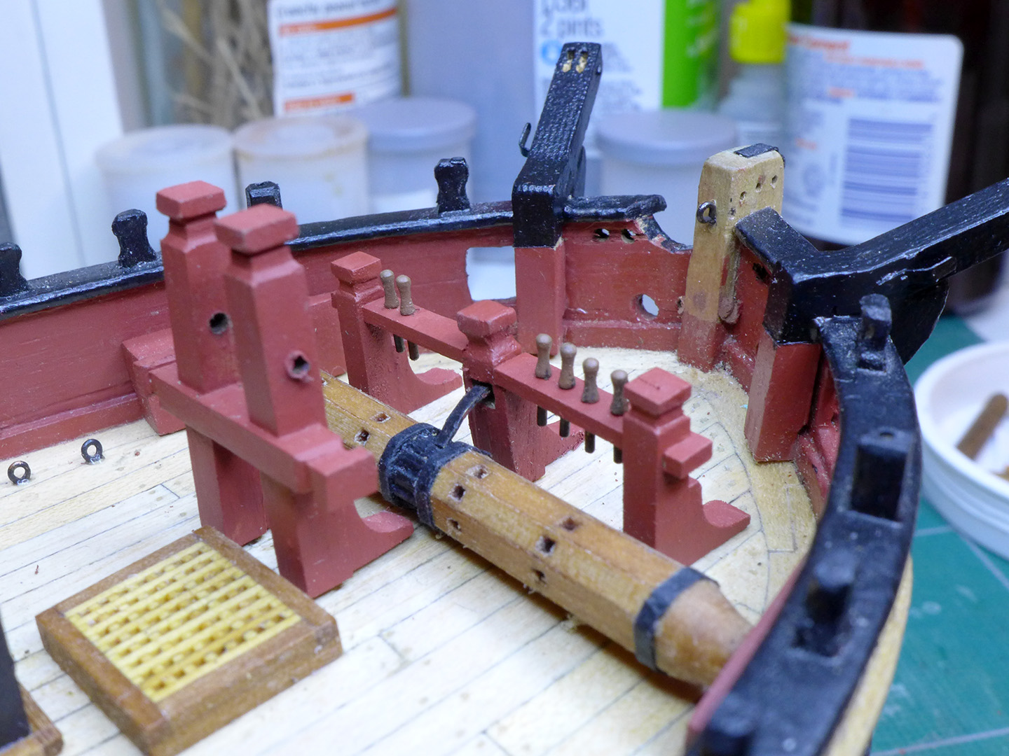
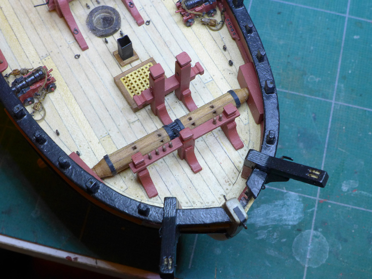
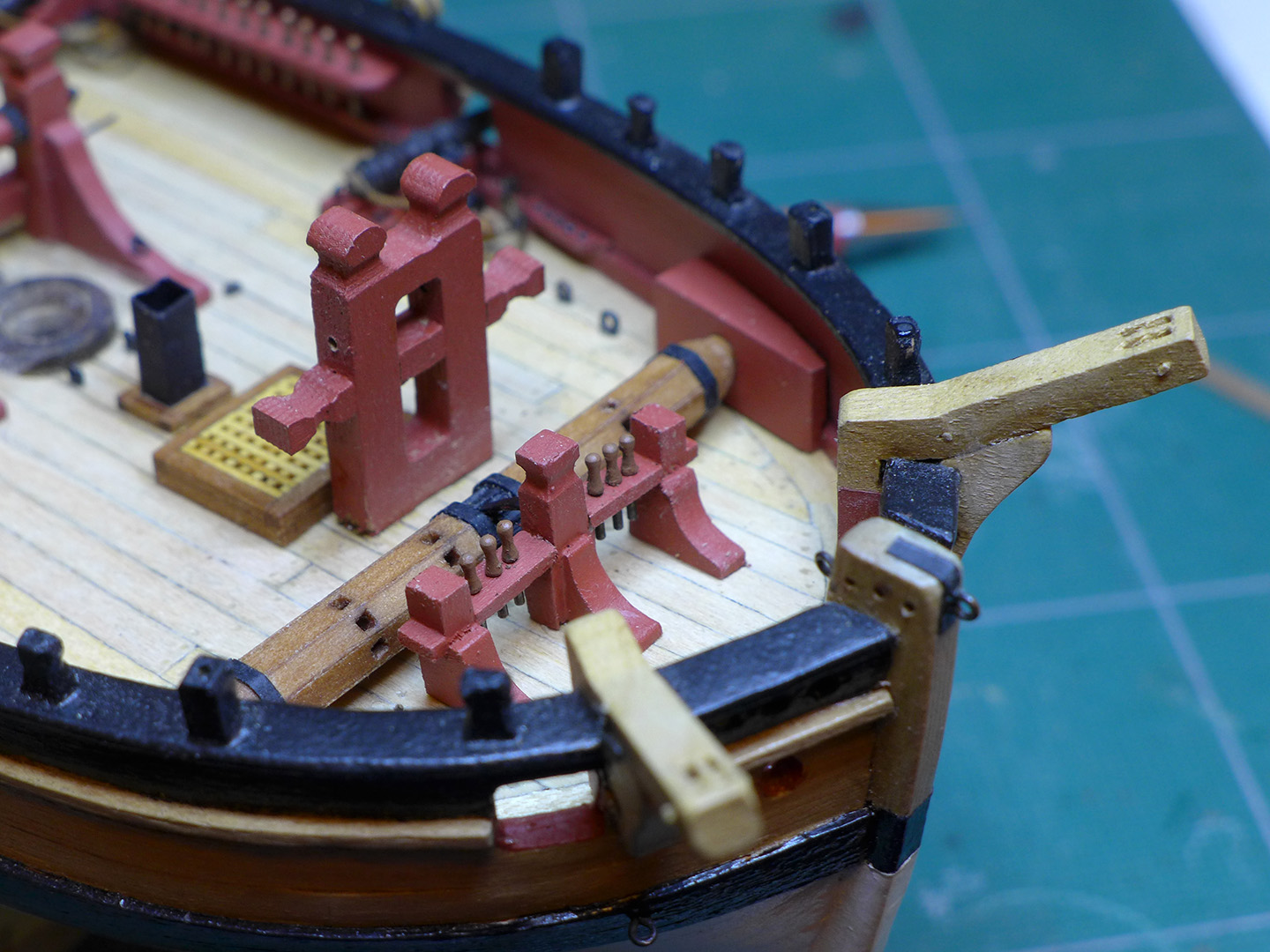
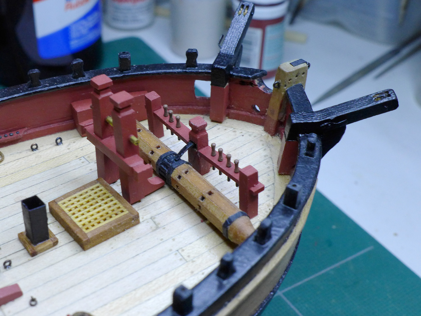
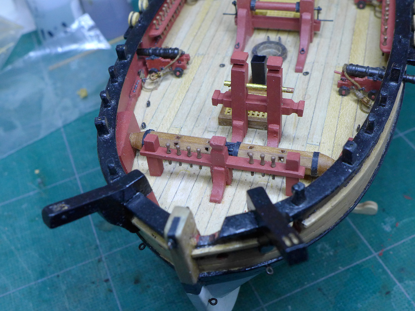
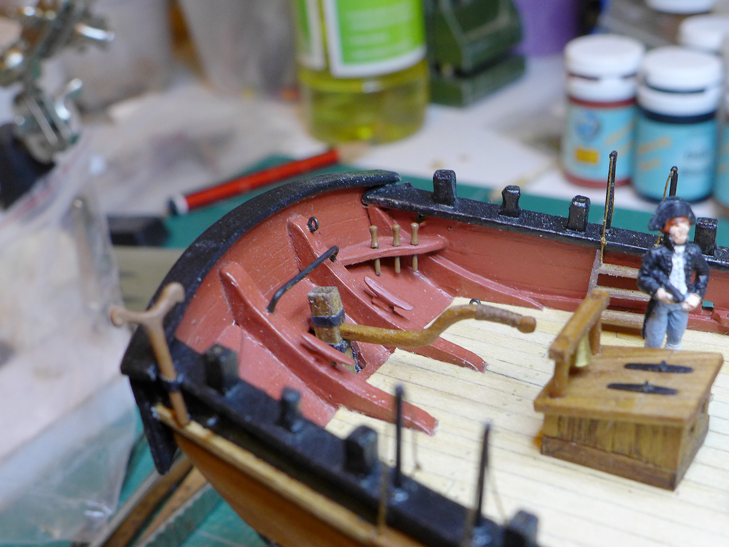
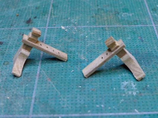
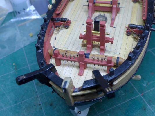
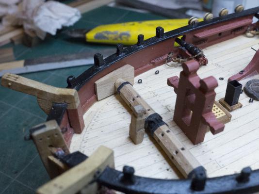
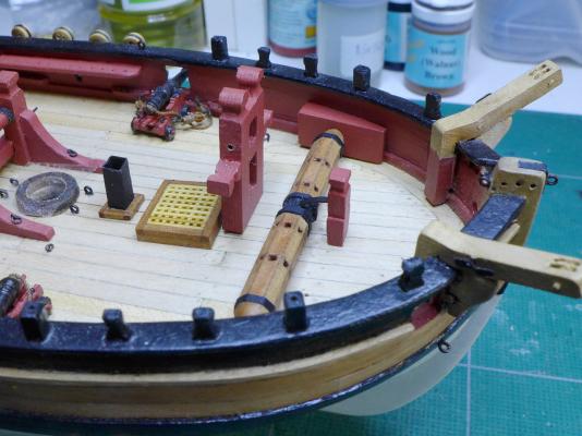
Just a small update. I've taken Kester's and Gregor's advice and re-fashioned the pin racks -- in the sense that I'm keeping the idea but making them higher so that the belaying pins do not foul the anchor cable. First off is a shot of the raw wood version. Now a shot to show the clearance. The angle doesn't show the extent of clearance, but it is two cable widths. The bowsprit clears the rail quite easily. Finally a shot to show the view from above. If anyone feels that this is totally out of historic possibility, please do go ahead and offer some suggestions. As you can see, I'm always willing to listen and modify in the light of wiser counsel! Thanks again to Gregor and Kester for keeping an eye on this question! Tony

- 269 replies
-
- 8
-
-
- Caldercraft
- First build
- (and 3 more)
-
Thanks very much, B.E. and Brian. Actually I'd like to keep stressing that it's me that is learning -- so really I am just feeding back the approach that you and others have intimated through your work. It's not just a question of the actual techniques used, but the way of thinking about problems as they arise. What is so interesting is that for almost every stage when I look at it first I can't believe I can do it. Then I settle down to think about it, and remind myself that the masters are just as human as I am -- so if they can do it, then I should be able to as well -- albeit with a lot of practice. I then try various approaches out, and something nearly always works in the end. I have done most of the steps about three or four times before accepting the result (as I have tried to stress in my log). Even if the finish is not quite as good as I would like, I have to compromise and say to myself that more experience will allow me to finish it better in future. Thus it's clear that my cannon are not nearly as nicely finished as most, but now I am confident that next time I do cannon I'll do them better as I have learnt from each part of their construction. For example, Brian, you'd be amazed at how easy the sheave was. I only attempted it that way because I couldn't think of another way to do it (I don't have a metal-working lathe), and my mind went back to using the wood lathe for turning the cannon barrels. I remembered how beautifully boxwood turned and all I needed was a sharp chisel. I thought it didn't really matter that the sheave wasn't metal. The groove on the rim was just with the tip of the parting tool in my set of Proxxon wood turning chisels. I myself couldn't quite believe how straightforward it was. You don't even need a wood lathe to do it -- I've seen examples of fine miniature wood turning using a Proxxon drill and home-made chisels. So take heart: most of the time you can do all of these little tricks. It just takes thinking of them, and that comes with watching what all the masters on this forum have done. Most of them will tell you that they too were novices once, and went through the same process -- which is why they are so willing to help out when you ask questions. You then learn more by doing it yourself and finding out what works for you with the tools you have. This is my very first model (apart from a few plastic kits 50 years ago) and if I can do it, then you certainly can! Soon I'll have to start the rigging. Believe me, I am really anxious about it, but I'm confident that once I start it'll all begin to make sense. Tony
- 269 replies
-
- 2
-
-
- Caldercraft
- First build
- (and 3 more)
-
Ah well, it was worth a try, and I am happy practising my joining skills. I'll have a re-think and see how to improve the rack at the bow. Thanks, Gregor and Kester, for the usual intelligent and insightful input. Tony
- 269 replies
-
- 2
-
-
- Caldercraft
- First build
- (and 3 more)
-
Yes, I thought about the anchor cable. I wasn't sure whether the cable would run along the ground, under the windlass, and then back over it. If it runs along the ground we're fine. Otherwise I could raise the rack so it is above the windlass, attached to the top of the pawl. What do you think. Thanks, guys, for the nice comments. You can all see I'm learning tons from you, so really you should all be giving yourselves a nice pat on the back for good mentoring! Tony
-
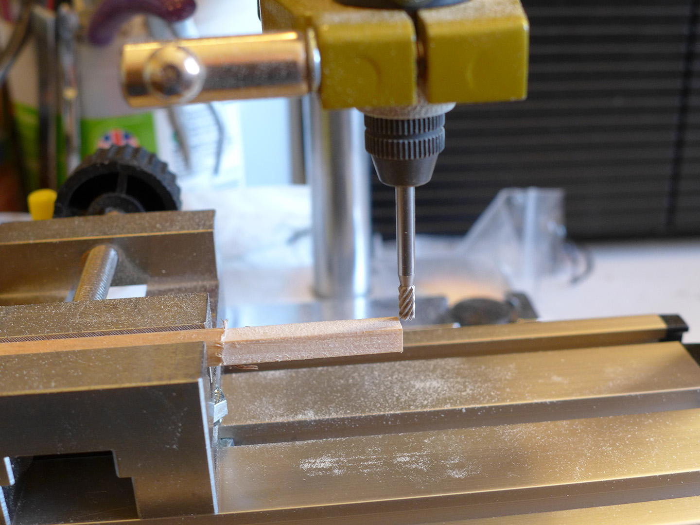
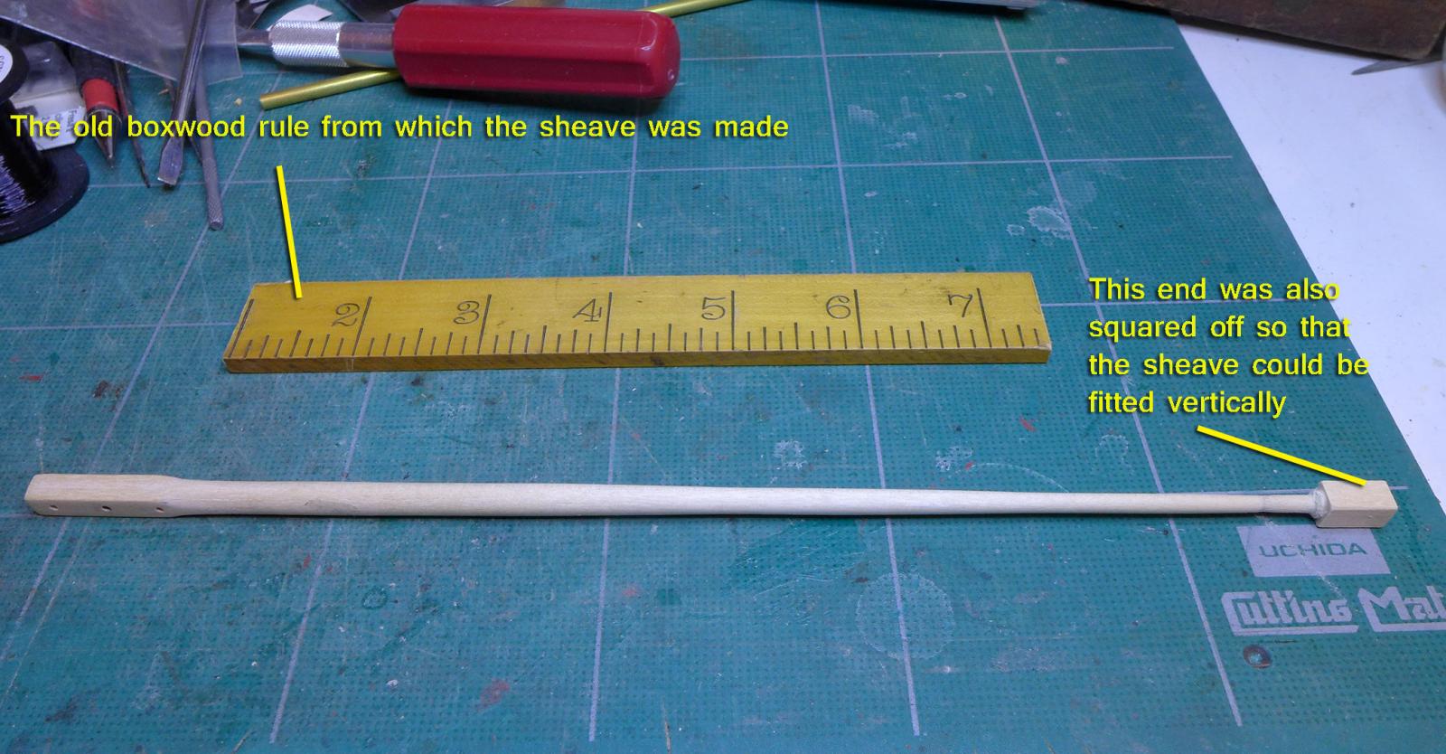
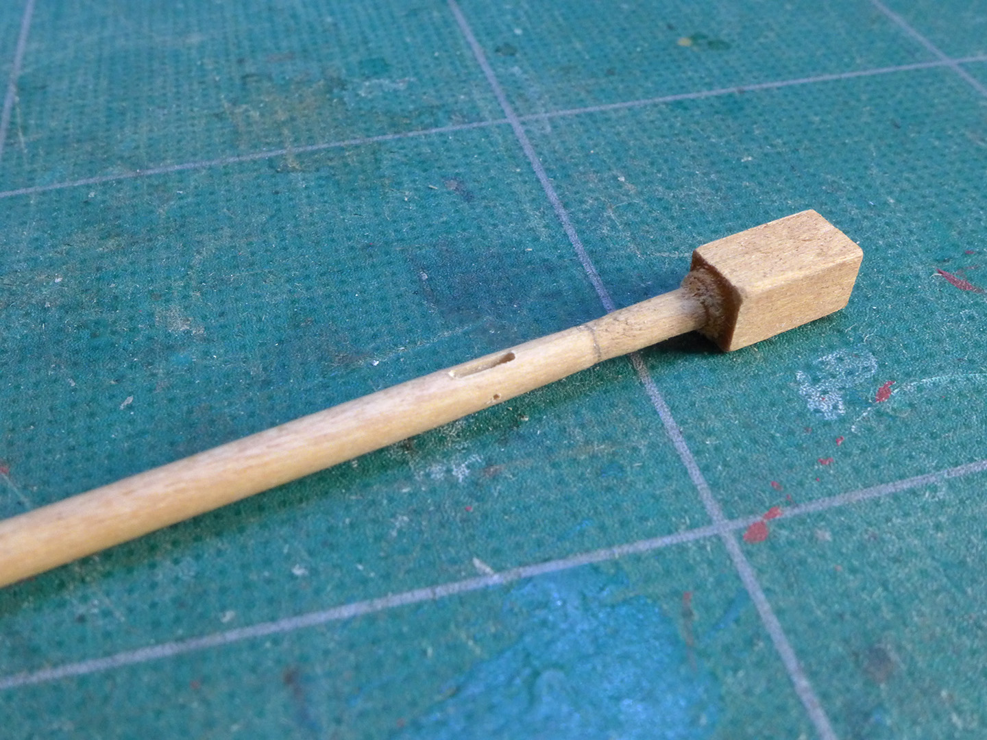
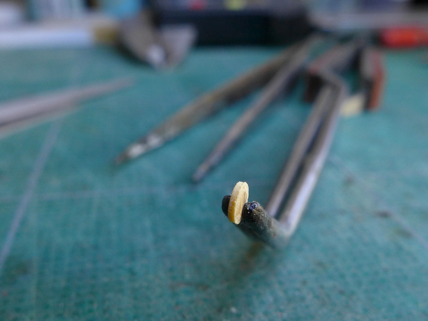
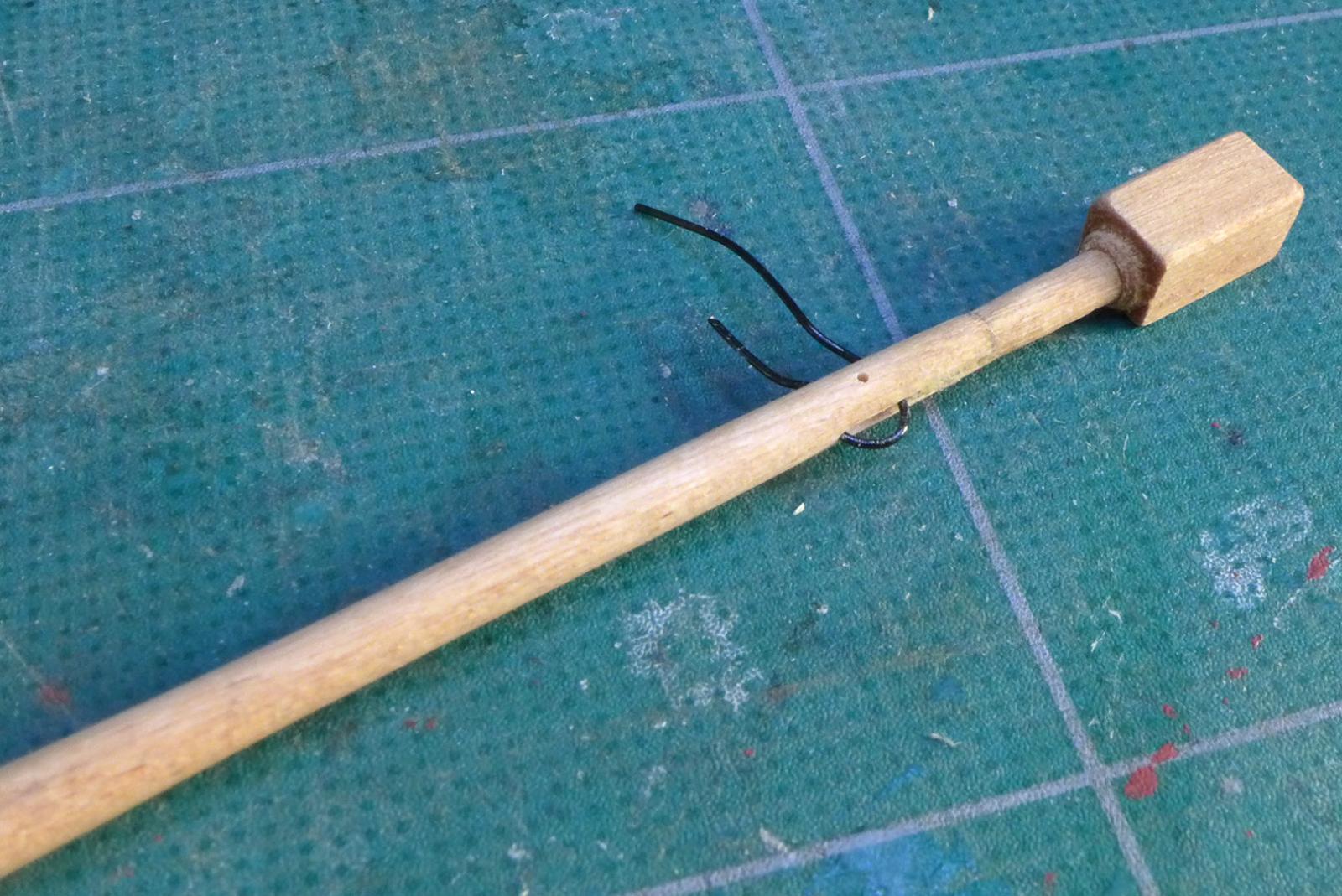
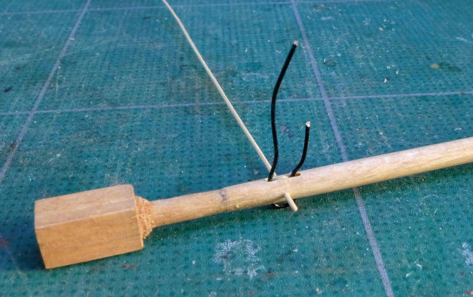
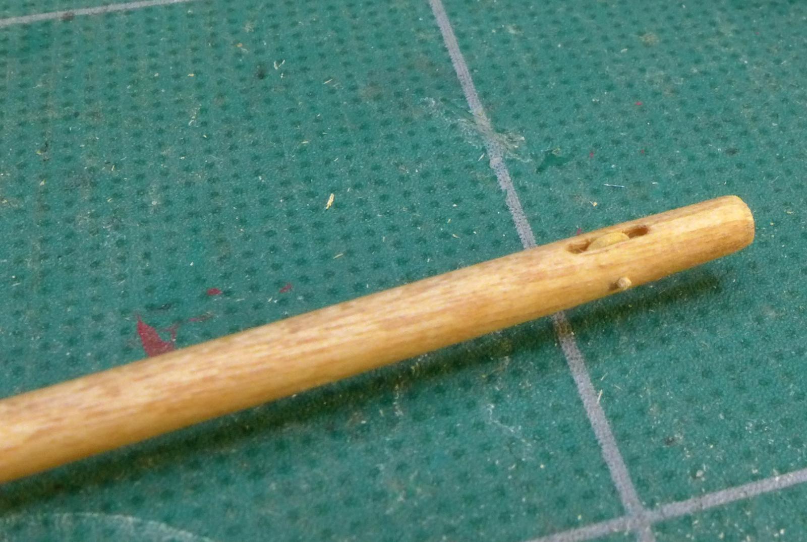
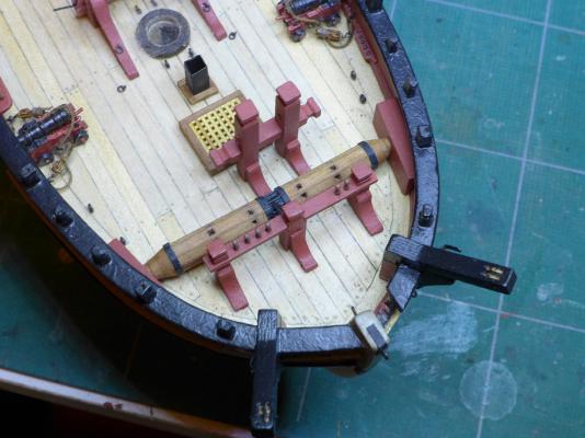
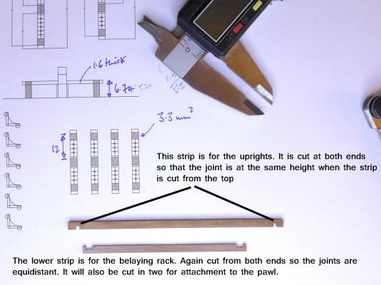
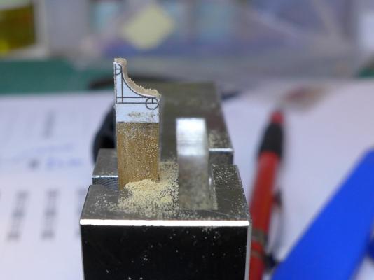
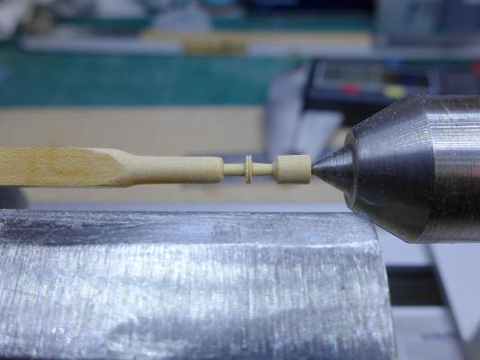
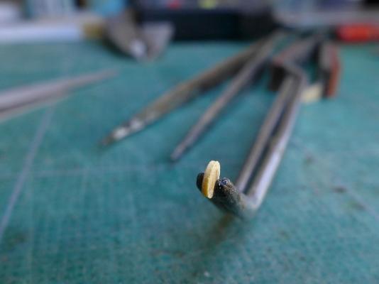
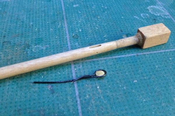
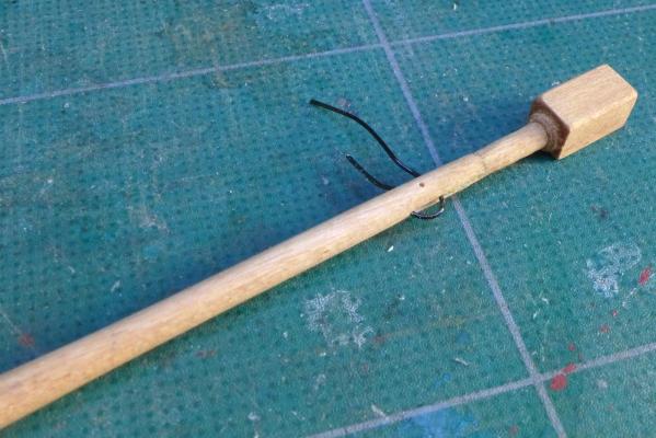
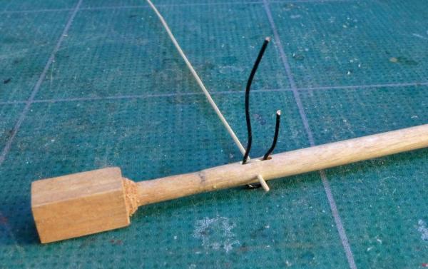
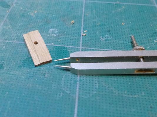
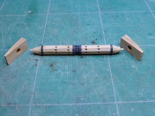
Belaying rack at bow Having decided on this type of windlass, it was clear I couldn’t follow the type of belaying rack that Dirk used in his build, or the type of rack that Petersson displayed in his drawings of HMS Expedition in the book ‘Rigging Period Fore and Aft Craft’. I also studied Gregor’s approach of putting the rack right at the stem, but decided I’d do something silly and make a rack attached to the pawl post. Again I drew up a set of plans with TurboCAD and used tracings to cut the wood and drill the holes. I cut out the joints using the table saw. A knee for the pawl was similarly cut out with a jeweller’s saw. My first attempt was to have a short rack on either side, as follows: However, as soon as I attached the bowsprit, I realised that the pins under the bowsprit would be hard to reach, so I modified the rack on either side to be longer. While doing this, I saw that the bowsprit I had made was going to be problematic, so I need to have a short digression. Bowsprit My first thought was to do as the kit suggests and square off the end of the kit 6mm dowel. This means that the squared sides have to be smaller than the diameter while the diagonals match it. I did do this, squaring off the kit dowel using my modified Proxxon drill stand as a mill. (See ‘How to modify Proxxon MB 140 drill stand to act as mill’ at http://modelshipworld.com/index.php?/topic/4539-how-to-modify-proxxon-mb-140-drill-stand-to-act-as-mill/?p=130660). However, looking at other builds and at pictures of contemporary models, it is clear that the diagonals are cut down to the diameter, leaving the square sides the same size as the diameter. This in turn meant that the kit parts for the bowsprit stand would have to be discarded as they are made with the idea that the kit bowsprit is squared down. So I re-designed the bowsprit stand in line with other builds, as well as contemporary models of cutters. You can see the modified stand along with the modified pin racks in the next photos. Having got that end of the bowsprit correct, I turned my attention to the sheave at the tip. I had used 9mm dowel to make the new bowsprit but I squared off both ends so that I could mill the groove for the sheave vertically and drill its axle horizontally. The groove for the sheave was quite easily milled out with a 0.8mm milling bit by holding the squared end of the dowel firmly in a vice. The sheave itself I made from a bit of boxwood that I had turned to a 3mm diameter. I cut the sheave to 0.6mm width on the wood lathe, making a small 0.3mm notch in the rim for the rope and then sawing off the remaining stalks. I held the sheave in a 0.5mm black copper wire to insert it into the groove and then drilled a 0.6mm hold transversely for the axle. I made the axle out of a piece of bamboo passed through a drawplate. It was now that I came to my current problem. I tried dyeing and staining pieces of dowel to see if I could achieve the kind of finish that others have achieved. I used oak dye, walnut stain, very concentrated tea, tea with ferric acetate made from steel wool dissolved in white vinegar (4% acetic acid), and refined linseed oil. Nicest was the plain tea but the finish was very blotchy. The linseed oil was good, but not dark enough. So I have ended up ordering pear wood, and will make the bowsprit, mast, boom and spars from that. I will also be spending time now on building a serving machine and making another ropewalk as my old electric shaver that I had modified has now given up its ghost. Tony


- 269 replies
-
- 7
-
-
- Caldercraft
- First build
- (and 3 more)
-
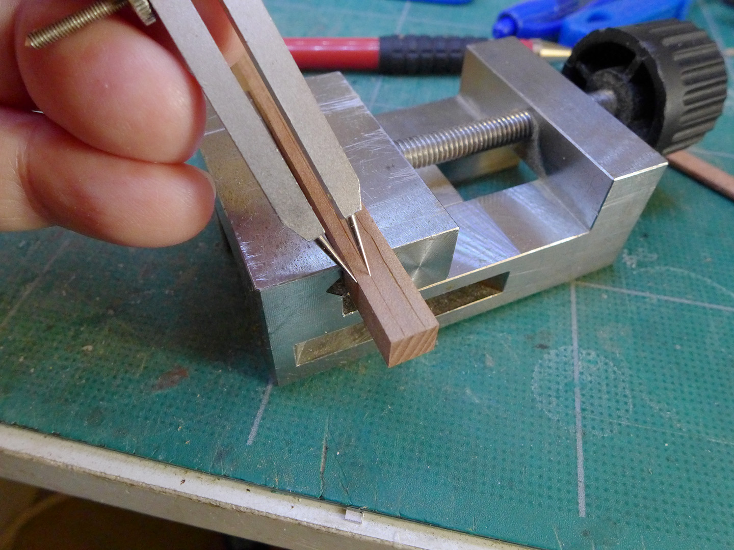
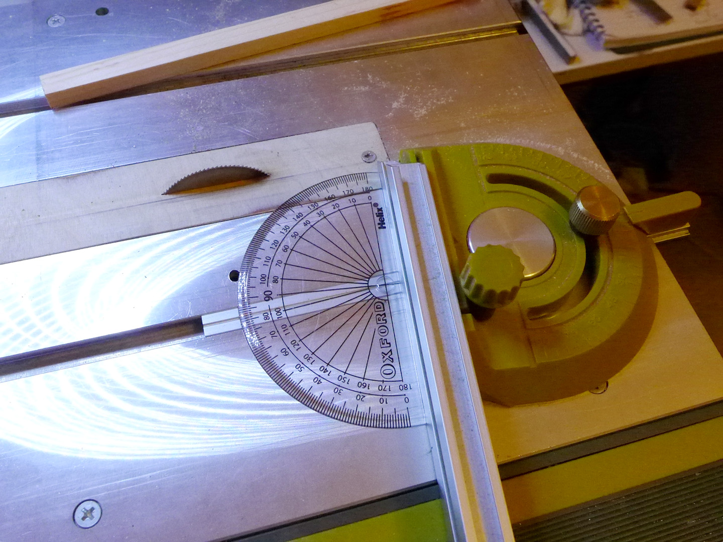
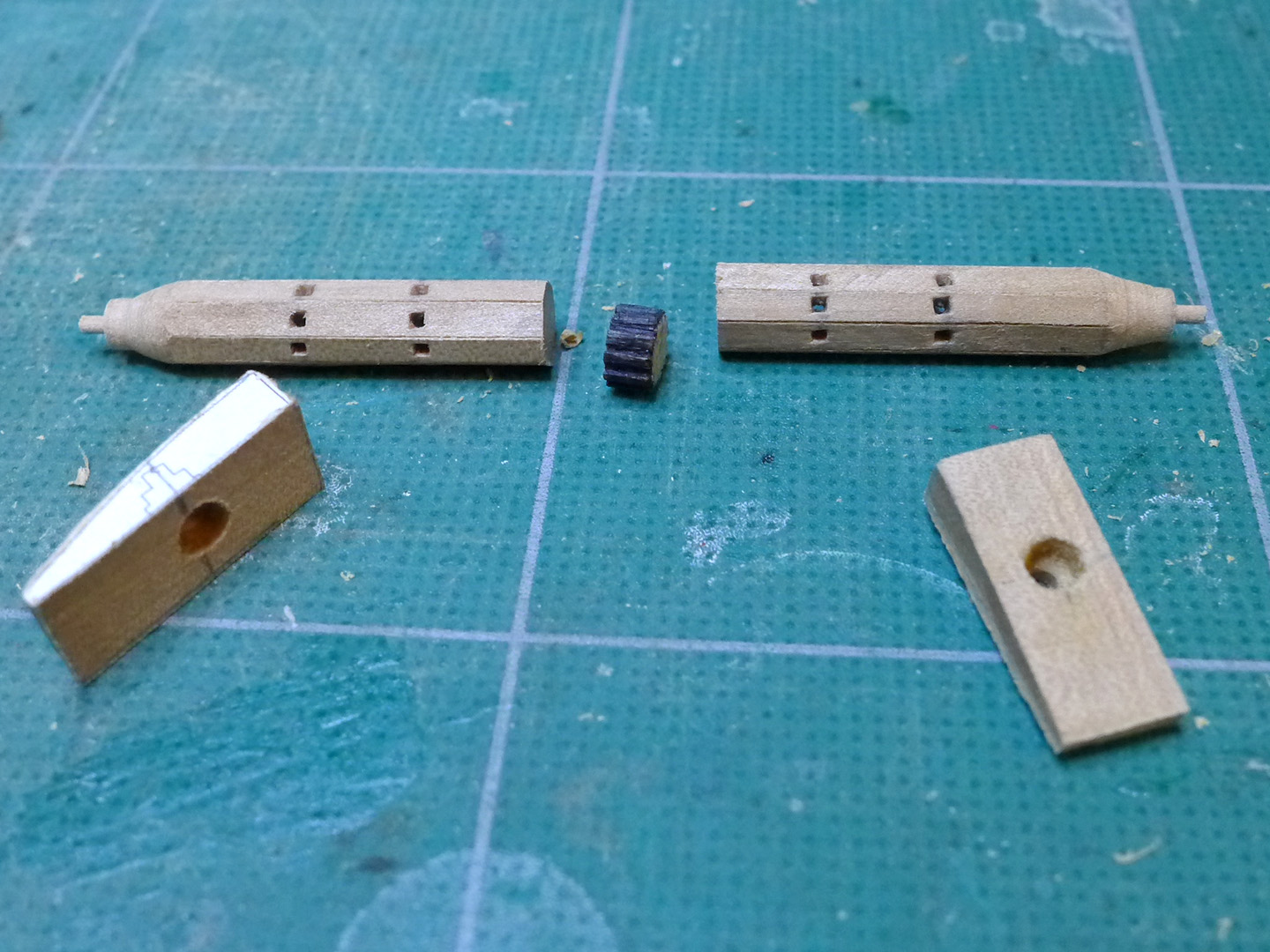
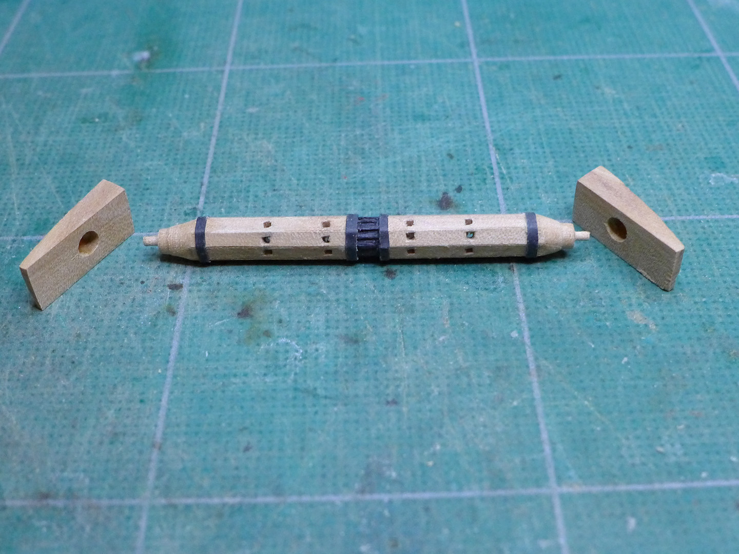
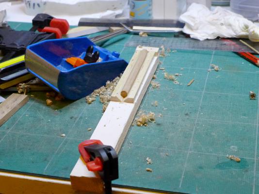
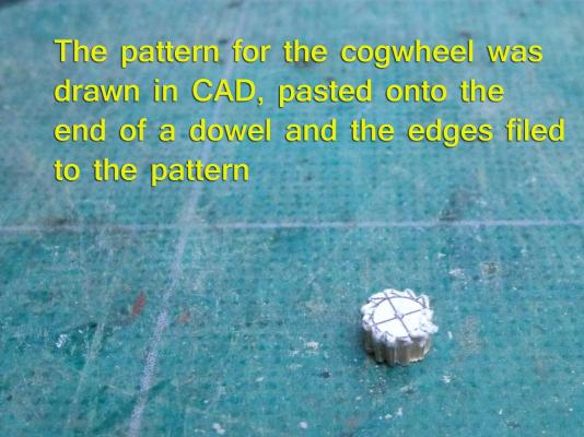
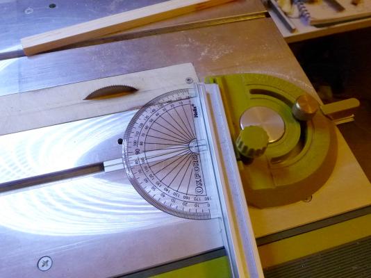
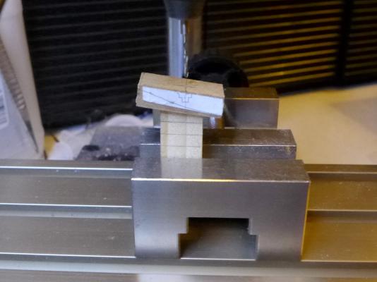
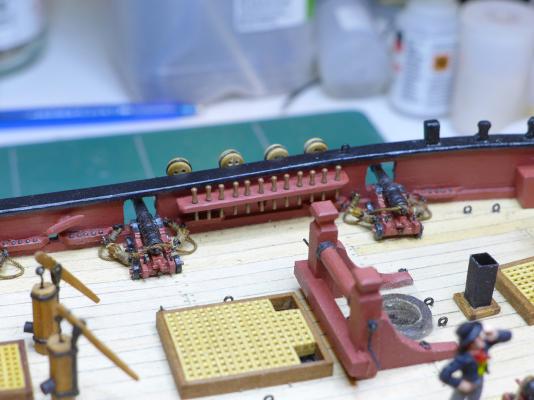
Windlass Again, looking at the plans, and at Gregor’s excellent example, I thought I’d have some fun trying to make a windlass as per the plans from the NMM. I drew one up in TurboCAD, and took a strip of pear wood and marked out the octagon with dividers as shown in the picture. I then made a jig with a Proxxon FET table saw. Luckily this saw can be tilted to 45o, so it was easy to cut two strips at that angle and lay them together as in the photo. The edges were planed off as far as the markings in turn using a small David plane with a razor blade. The pattern for the cogwheel was drawn in CAD, pasted onto the end of a dowel and the edges filed to the pattern. The windlass is held by two blocks fixed to the bulwarks. Again a plan was made with TurboCAD. The windlass enters the blocks at an angle of 82o. In order to drill the hole at the correct angle, a protractor was used to set up the table saw. A stick of ordinary wood was then cut at that angle and used as a base for the block. The hole for the windlass was then drilled with the drill stand. Because the block also abuts against the spirketting, a chisel was used to carve space out from the edge of each block. The windlass was then put in the wood lathe and the ends turned to make the holding rods as per the plans. The windlass was then cut in half and the two ends glued to either side of the cog wheel. Holes were drilled into the windlass and squared off with a steel nail. Black paper bands were placed around the windlass to simulate iron bands. Note that the pawl assembly and the bowsprit stand are not yet glued to the deck. These will be replaced with new assemblies as will be seen later in the log. The assembly was then glued to the bulwarks. Tony


- 269 replies
-
- 9
-
-
- Caldercraft
- First build
- (and 3 more)
-
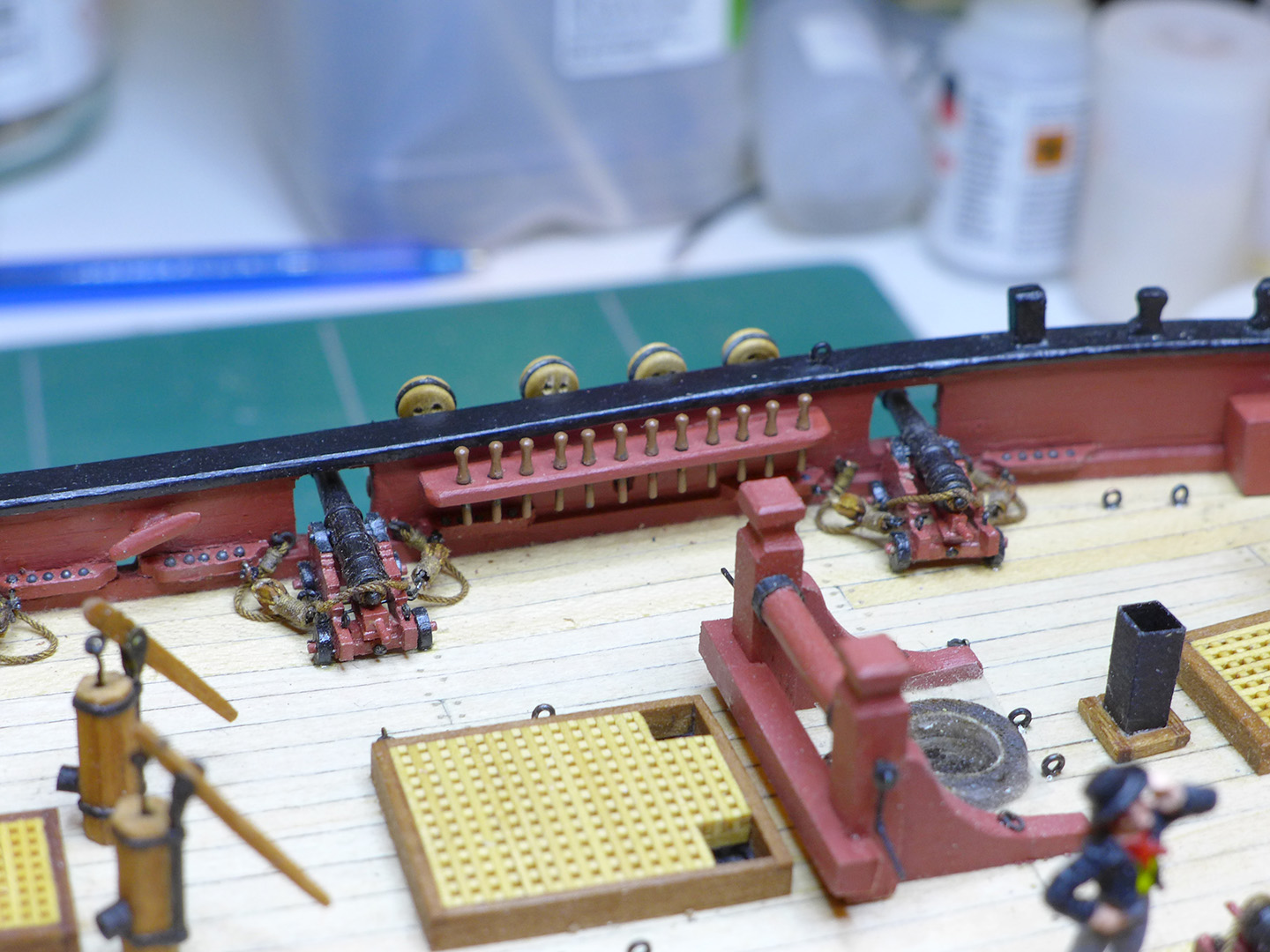
Pin rails Following the other Sherbourne builds, I put pin rails at the stern, and modified the ones under the main mast shrouds. The kit’s belaying pins are way too large. I had to buy the belaying pins as I found I couldn’t make wood ones small enough (although I now realise I could do so with boxwood). I coloured the brass ones with brown paint to make them look a little more like wood. You’ll notice the square galley pipe I put in, following the plans for the Cutter Alert. I also decided to omit the pin rail that is provided in the kit to go in front of the mast. This is because I felt the deck was really crowded at that point, that the galley needed some space below, and that I might be able to have enough belaying points anyway. Let’s hope that’s right! You’ll also note the strip of Sellotape I have put across the mast hole to stop small pieces being lost down that hole. Tony

- 269 replies
-
- 7
-
-
- Caldercraft
- First build
- (and 3 more)