
DONATION DRIVE - SUPPORT MSW - DO YOUR PART TO KEEP THIS GREAT FORUM GOING!
×
Jsk
-
Posts
279 -
Joined
-
Last visited
Content Type
Profiles
Forums
Gallery
Events
Everything posted by Jsk
-
 Wow! There must be a more sane method to make railings. I at least I hope so for my current project's sake!
- 288 replies
-
- 4
-

-

-
- Card
- Pre-Dreadnought
- (and 3 more)
-
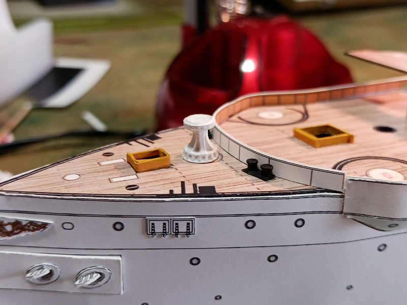
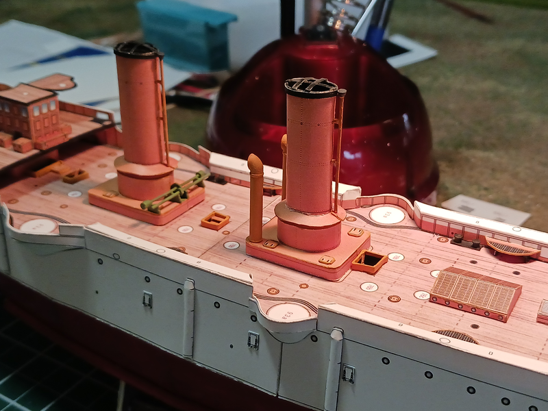
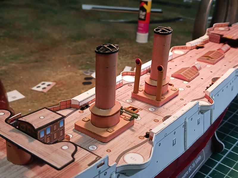
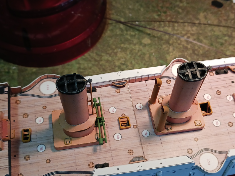
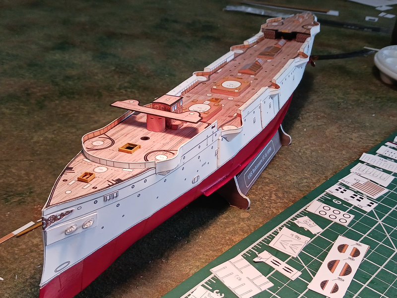
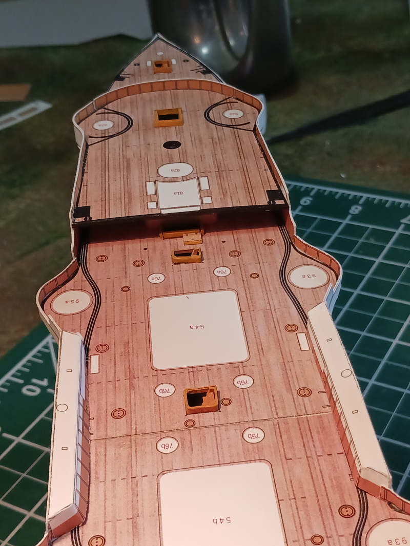
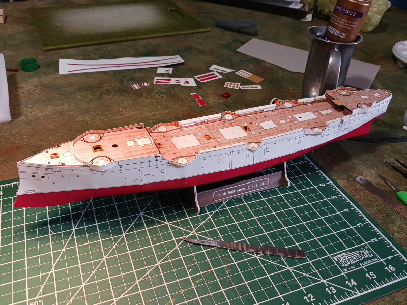
Wow... has it really only been 14 days since my last update? Non-hobby life has made me feel like I've aged 10 years. Anyway... Thanks all who have like and visited. It is appreciated. I found the stacks to be surprisingly challenging. First off, the card I'm using is probably a bit too thick so the cylinders of the stacks did not want to roll smoothly. As designed, there are two sloping flanges on each stack; one at the very top and a larger one down lower where the diameter of the funnel decreases. The larger flange was fairly easy to glue together and slip over the cylinders. The smaller ones at the top edge defeated me so I took a different approach to finishing the stacks. I put in cross members and then simply wrapped card around the top to add a lip. I like the way they look. In various pictures of the Baltimore you can see that there was something up there but I've not seen it in any clarity. I think it's a safe assumption that there were some type of supporting cross members in the stacks. I also abandoned the idea of making the steam pipe and the steam winch out of card. They are both constructed of plastic sprue. Finally, I'm also getting the chance to attach some of the 3d printed parts. The capstan, bollards and two of the vents have been installed. The rest of the vents are on the painting desk now and will go on next. I think the next major sub-assembly will be the primary and secondary armament.
- 37 replies
-
- 5
-
-
- Baltimore
- heinkel models
- (and 2 more)
-
The Black Ship is looking menacing! If I understand what you're doing that seems like a lot of work for the railings. Are you cutting out the voids? All the little rectangles between the posts and railings?
- 288 replies
-
- 5
-
-

-
- Card
- Pre-Dreadnought
- (and 3 more)
-
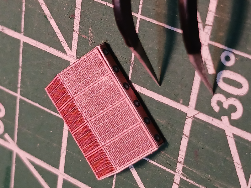
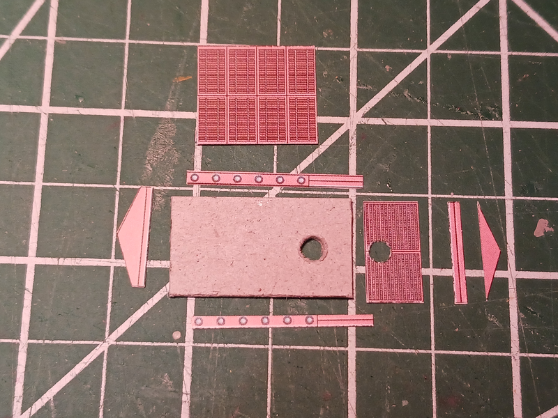
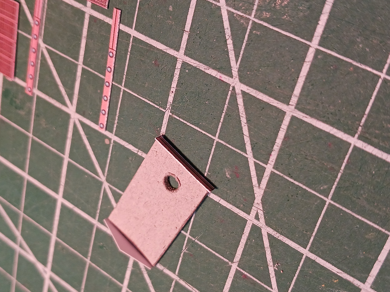
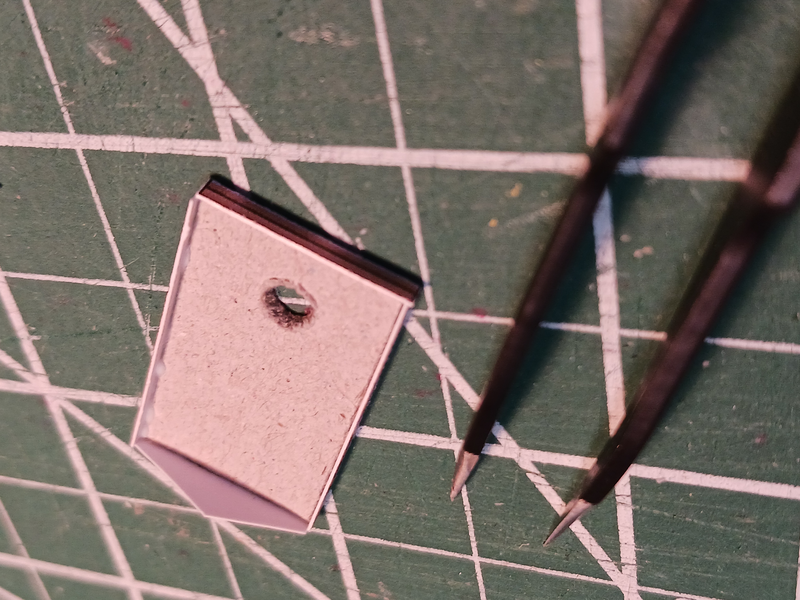
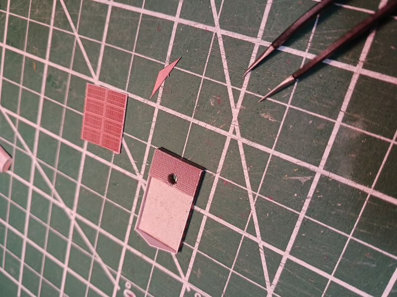
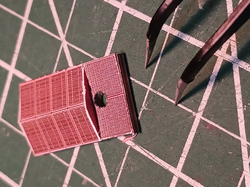
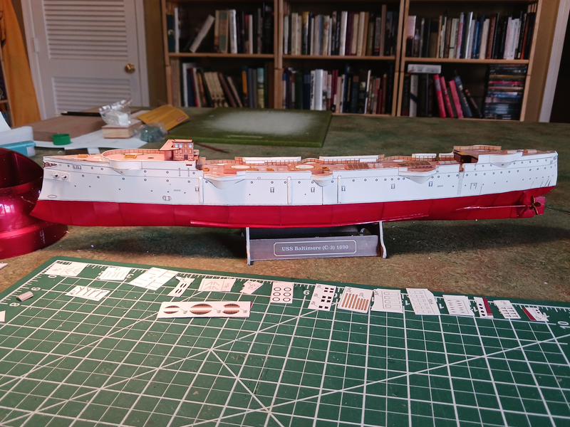
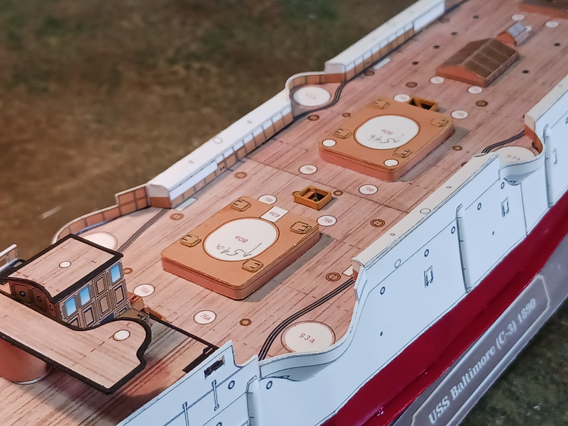
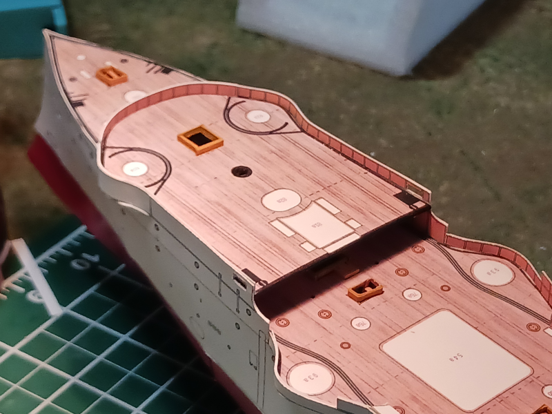
Yes, painting the sub-surface hull was definitely the right decision. Looks much better and I'm feeling pretty good about the whole model now. Adding the hatch covers on the hull and the other exterior details really helps move the whole thing to a higher level. I'm now working on the deck houses and skylights. I have found, however, that scoring and folding the small pieces leaves me cold. It might be because I've used 110# card for the whole thing and I think that's probably a bit heavier than what the design was intended. I just haven't been able to get crisp folds and being laser printed the toner tends to flake off at the folds. So, I'm avoiding folding and cutting all the sides of the structures separate. That of course means I have more edges to paint (and try to color match!) but I'm ok with that. It also means that I've been cutting 1mm card to use as a support piece inside the structures. The next step will probably be the stacks.
- 37 replies
-
- 3
-
-

-
- Baltimore
- heinkel models
- (and 2 more)
-
Speaking of time, how many hours of printing is that? They look great.
-
I rarely visit the gallery section. While it can be inspirational I learn a lot more from the build logs. Can't say I'm a fan of videos in either place.
-
Well, as the younger generations say "You do you!" Nevertheless, your models are still stunning.
-
I suspect that first coming out of the yard probably the cheapest paint had been used. But Captains had a lot of discretion when it came to maintenance. Some had more money to spend than others.
-
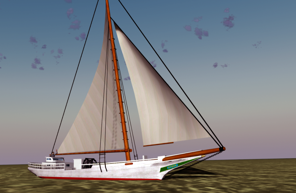
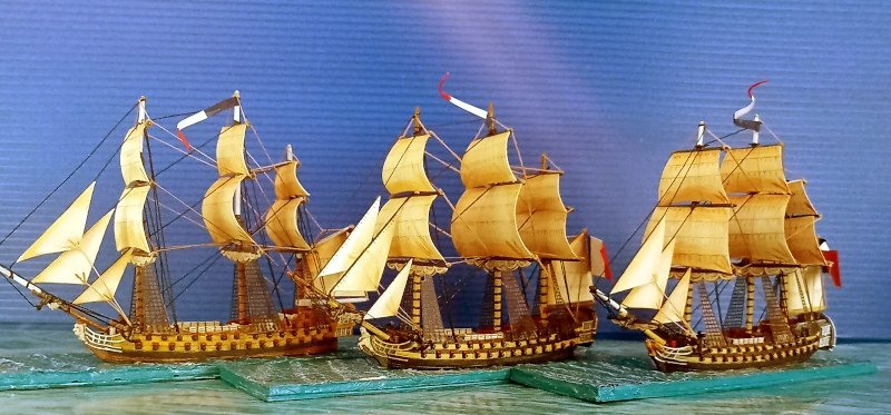
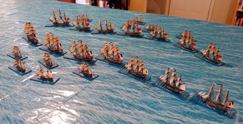
Welcome, Linus! Your 1/700 models look great. My Covid lockdown project in 2020 was a French and a British fleet so I understand the challenges of these models. Though I've never actually played a game with them that was certainly the intention. Are your ratlines 3d printed? I wasn't impressed with the clear ones provided in the kits but wasn't able to find a better alternative. Also, (I'm finally asking this question after observing it for years)--why don't your driver/spanker sails extend all the way to the mizzen mast? I've only seen this on 'gaming models'. I suspect it's just incorrect mostly due to Warlord designing their models that way and builders following along. Still... I'm no expert. Cheers! PS, your gaming mat is perfection.
-
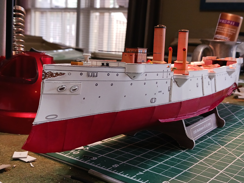
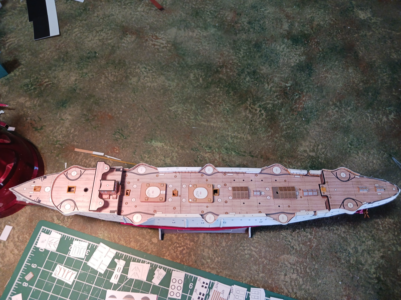
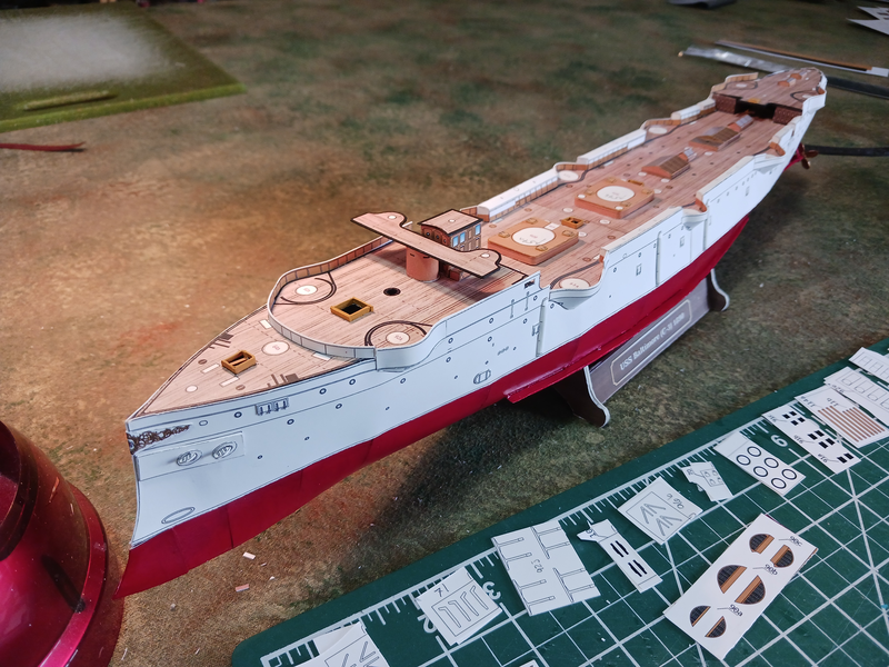
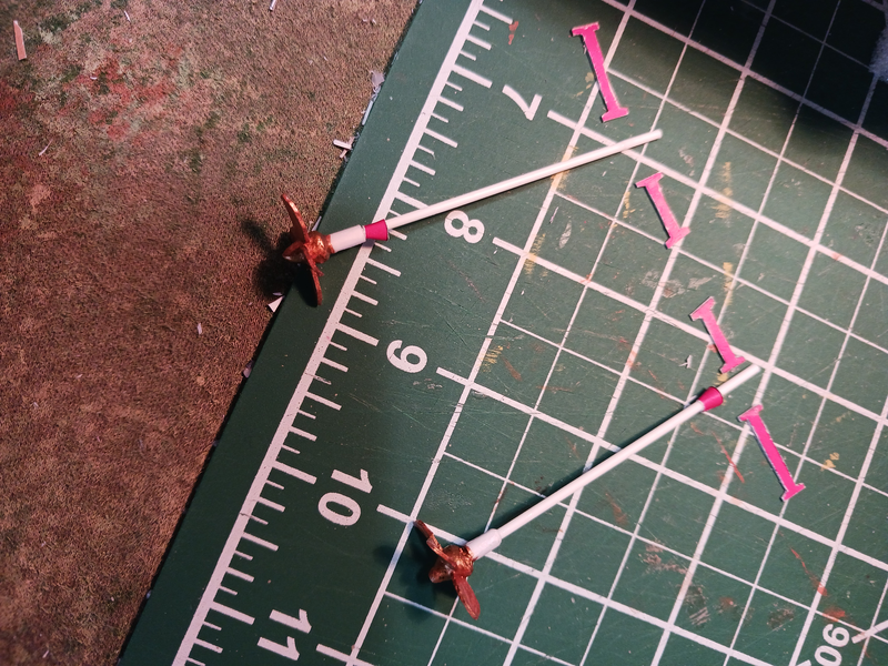
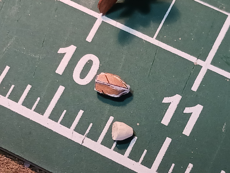
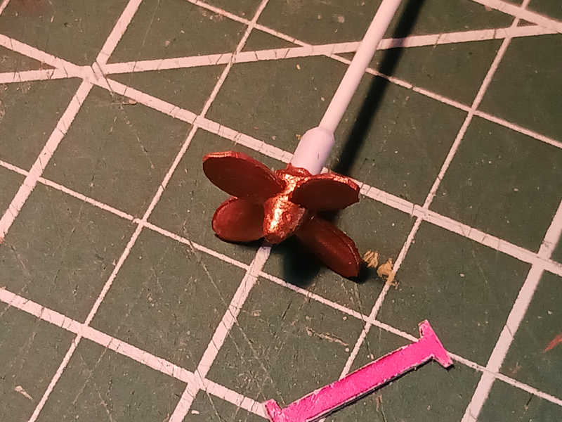
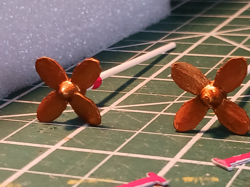
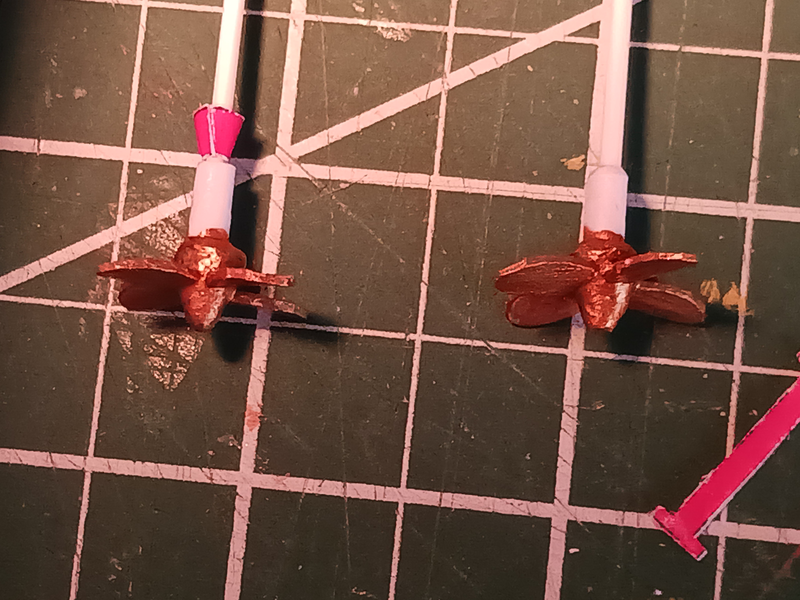
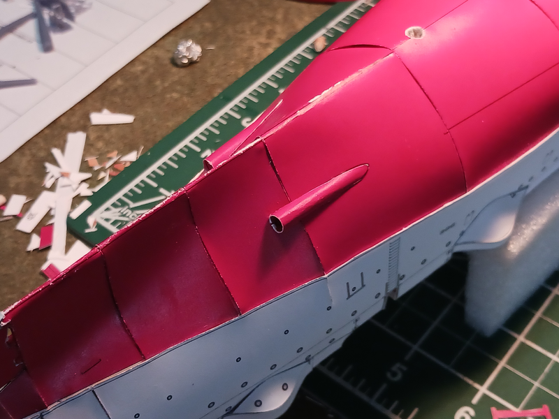
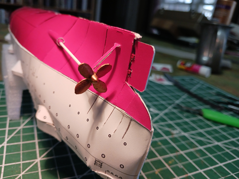
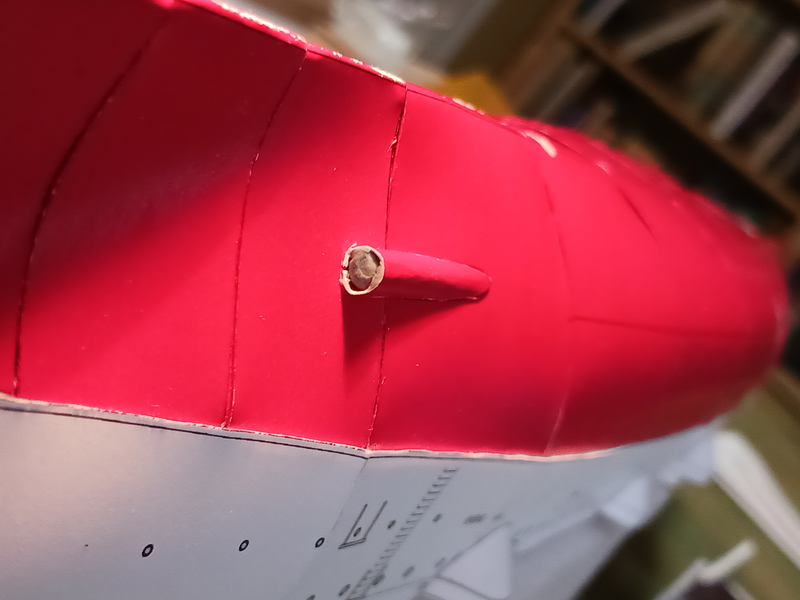
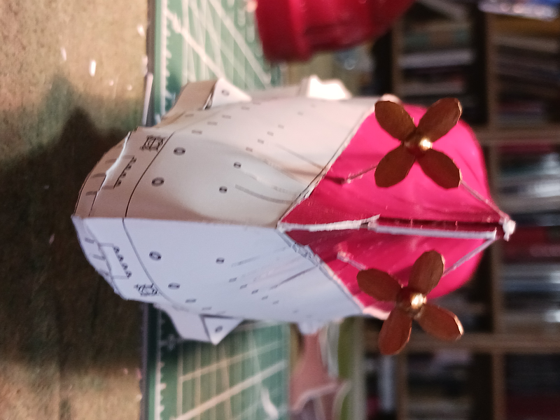
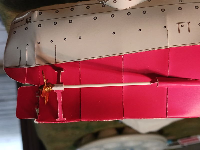
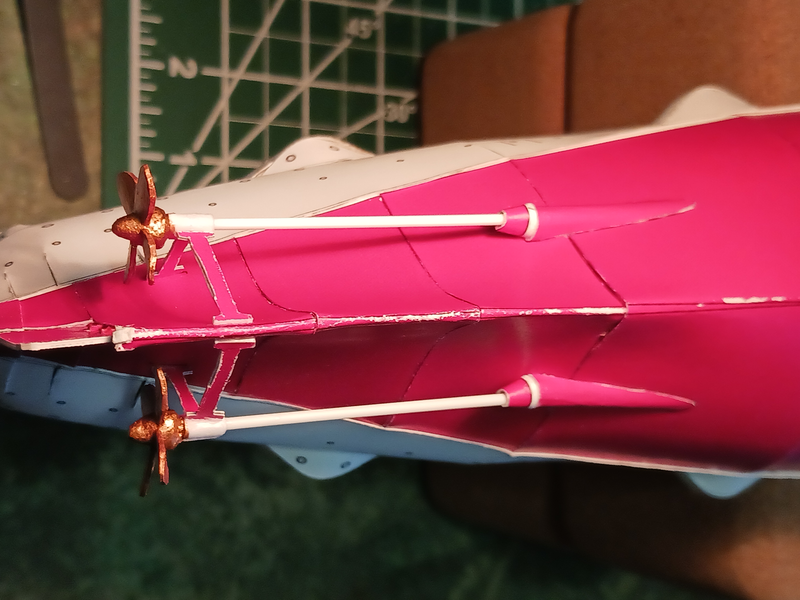
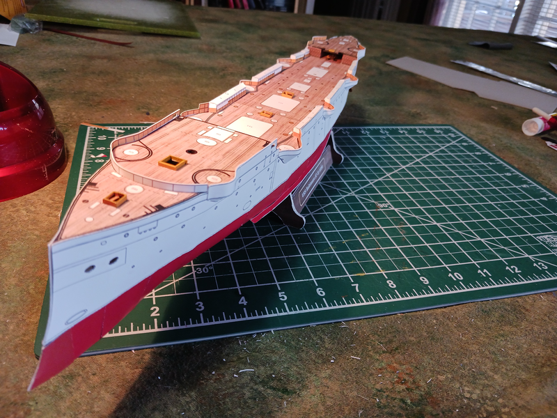
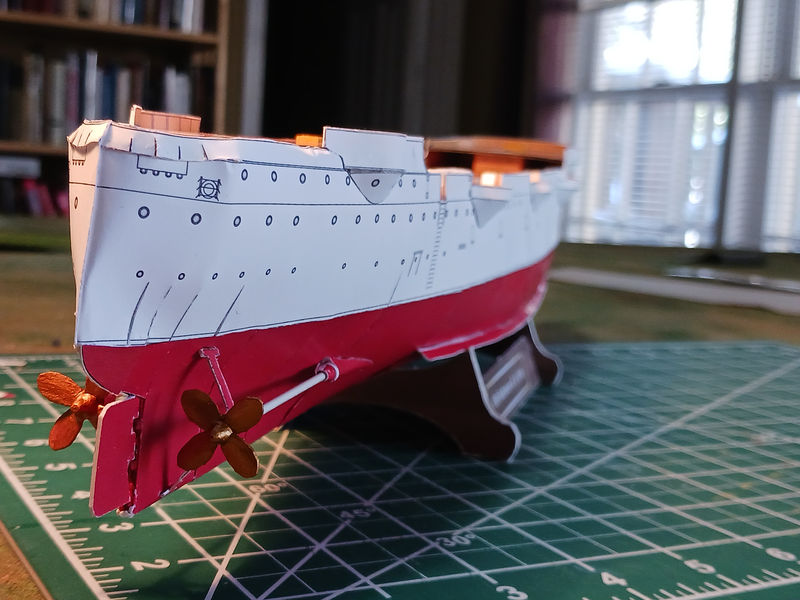
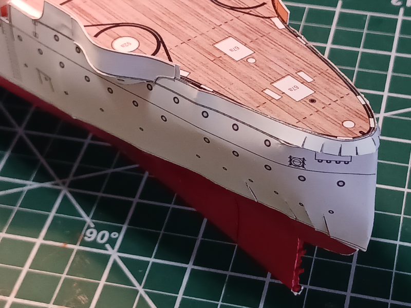
Thanks for stopping by and likes, everyone. Today is the second day of forced leave due to weather events in the DC area. Since I don't telework I'm forced to use my accrued leave. Frankly, I had other plans for my leave hours 😞 . I am so looking forward to NOT being a federal government contractor. Oh, well. On the up side, except for some painting I think I've got all the below-the-waterline work done on the Baltimore. It was all a little challenging. I wish I'd studied the parts a bit more when I was designing the parts for 3D printing. I would have/should have include the propellers. The propeller hubs were too small for me to assemble. I could cut them fine, but the tiny petals of the bullet shaped hubs defied my ability to glue them together. So I fell back on my scratch building skills. I placed a bullet shaped lump of plasticine clay on the end of plastic rod, covered it with several coats of CA to firm it up and glued the propeller blades to the new clay hub and painted the propellers bronze. I then wrapped paper round the shaft to achieve the correct diameter for the propeller supports. After gluing the shaft fairings to the hull and the longer of the two supports to the prop shaft I inserted a little 'blu-tac' into the fairings. That allowed me to insert the shaft into the blu-tac to hold the shaft steady while I glued the long prop support strut (which was already attached to the propeller/shaft assembly) to the hull. Once that dried I could then attach the second support strut to the the shaft giving the whole assembly three points of contact with the hull. Once that was done I realized that the conical pieces that reduce the fairing openings to the shaft diameter were too small. So I had to cut off the original ones and cut new larger cones. Gluing them onto the shaft while it was in position was tricky but not impossible. I also took the opportunity to glue on extra pieces at the bow and stern to match the length of the underwater hull to the length of the white, above surface portion of the hull. After that, attaching the rudder and the bilge keels was fairly straight forward. I think I'm going to end up painting the entire sub-surface hull. I wanted to avoid doing that since I went to so much effort to change the red color in the printed parts but ultimately I think it will look better.

- 37 replies
-
- 4
-
-
- Baltimore
- heinkel models
- (and 2 more)
-
That green margin plank will make a nice color detail. It goes well with the deck color.
-
Fokker D.VI by ccoyle - MPModel - 1/33 - CARD - TERMINATED
Jsk replied to ccoyle's topic in Non-ship/categorised builds
Late to the party as usual... However, my thought was that the mystery parts were a fairing for an instrument. The one in front curves above the deck for aerodynamic purposes, the one to the rear forms the lower curve of a depression into the deck allowing better view of the instrument. I've seen that configuration but I'm not sure on what particular aircraft. Still, it's shaping up to be a nice unique model. Even if it is half guess-and-glue. -
Huh! There are a few locations I haven't thought of for many a year! In 1980/81 I lived in Vallejo and worked for a contractor refurbishing mobile military shelters. I drove a pickup and towed the shelters across the causeway from Mare Island to the shop downtown and back when they were finished. Vallejo was pretty blue-collar at the time. Mare Island was still active though I don't think there was much going on. I was excited to spot the USS Nautilus there--even then I was something of a nautical nerd. IIRC, Nautilus had been decommissioned and was having the reactor removed. I'm sure the town has changed over the past 45 years! I'm sure the Serv-O-Matic will do you proud!
-
Inspiring as always. I know the Card Purists would run me out of town on a rail but I really like the look of the Syren blocks.
-
Yeah... not a pleasant man! I wonder if he's leaning against a gibbet? If not, I think that would be an appropirate mod.
-
'Sailing Alone Around the World' should be required reading for all MSW members. One of my favorite books of all time. I'll be enjoying watching your build.
-
Fokker D.VI by ccoyle - MPModel - 1/33 - CARD - TERMINATED
Jsk replied to ccoyle's topic in Non-ship/categorised builds
Is this really a design issue or a production one? Maybe the manufacturer simply used the wrong thickness of card for the laser cut parts? Still, a better design may have helped identify the problem earlier rather than after constructing the cockpit. A rare plane. I'm not sure I've ever seen another model of a Fokker D.6. Looks like a Dr.I fuselage mated to D.VII wings. -
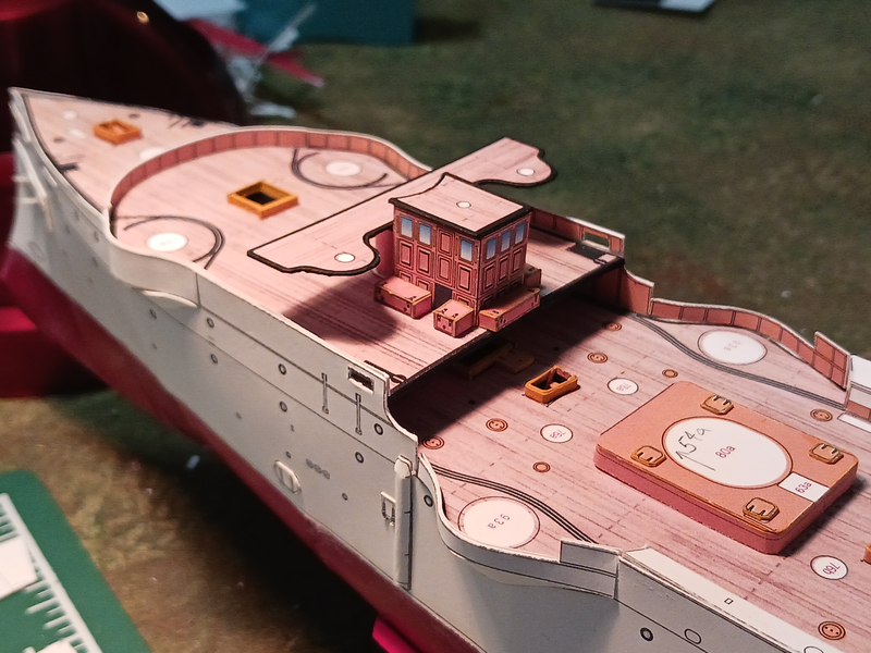
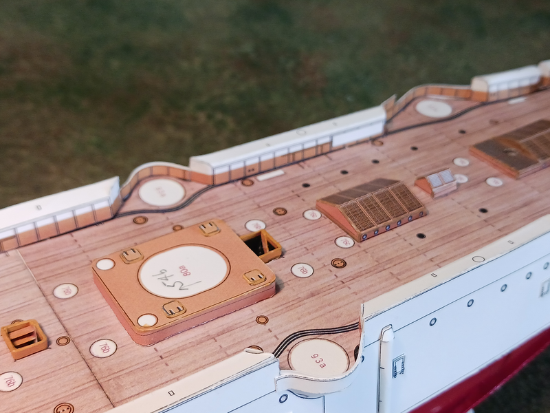
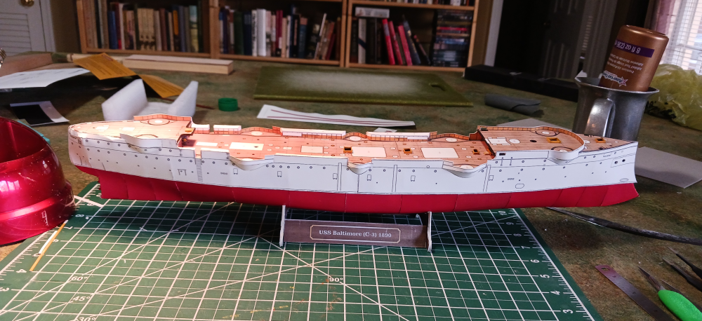
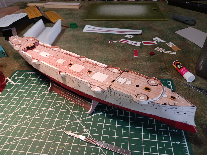
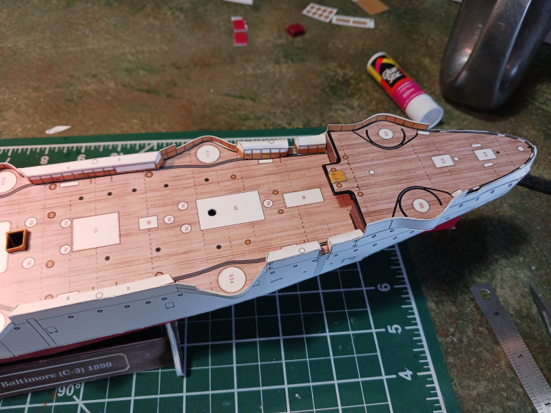
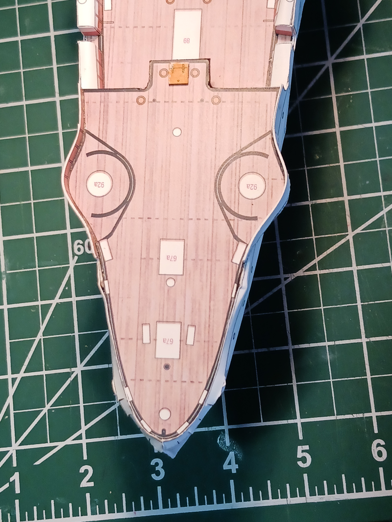
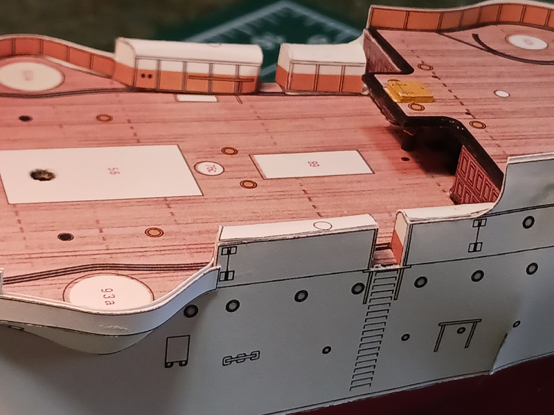
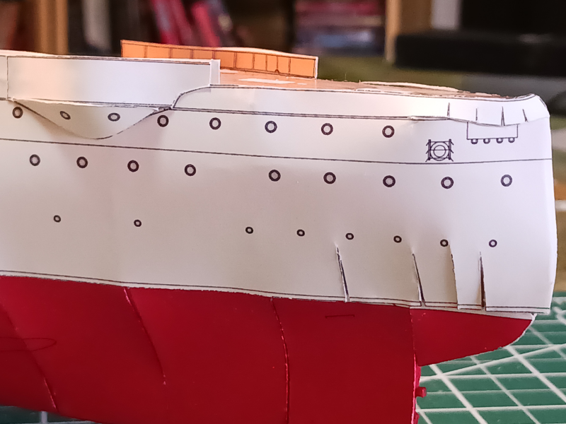
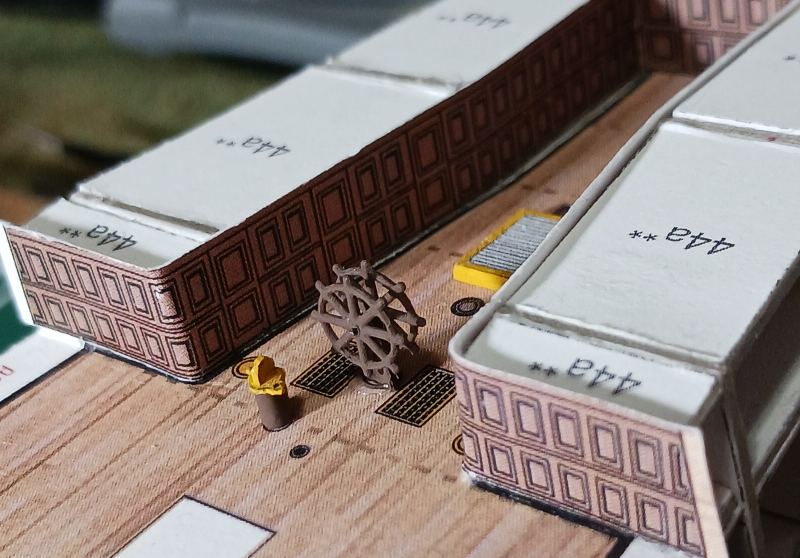
A shout out to MSW's own @JerryTodd ( a 'scholar and a gentleman' as they say) for helping me out with the remaining 3d printed parts. I've had them in hand for a few weeks but real life has reared it's ugly head again and slowed modeling progress. I've been attended twice weekly physical therapy to address some back and knee issues--but that comes to an end next week. (Yay!) Nevertheless, I finally made some significant progress on the Baltimore by skinning the hull and assembling the sides and sponsons. The next step is to install the rudder, propellers, shafts and bilge keels then I'll start on the funnels and deck fittings. Here's the first of the 3D parts installed. If you scroll back a few posts you'll see how the resin wheel is so much better than my bungled card wheel. I have to admit that I almost binned the project because of the stern. It's... well, lumpy. I'm not sure what went wrong. I suspect I don't have the aft decking placed at the proper place but for the life of me I couldn't see where it could go anywhere other than where I put it. Granted, the stern on this ship is a complex shape to form in paper. And my lack of experience... er, learning curve, doesn't help. But after pushing through I decided that it's all about developing skills isn't it? I've got the trash-toss down pat--I don't need to practice that! Maybe some judicial use of white paint will make the stern issues less obvious. This is the kind of shape that would be so much easier to shape in wood than in paper. In addition I see many small details that bug me. Things like the misalignment of the upper and lower hull sides will take some creative solutions but I think I'm over the hump. I just now noticed that maybe I used the wrong sponson fairing pieces? The historic ship had one port hole in the rear sponsons and two in the front. My model has it the other way around. Hmmm... I'd have to check the assembly drawings on that one. No matter. It's going to stay the way it is. One of the biggest challenges I've had is that I don't have any type of jig to hold the model still as I work on it. There is no keel to speak of so I've not been able to clamp the hull to anything. The model has little weight and the hull is quite round in cross section so it likes to roll out from under my hands as I try to attach parts. I'm trying to handle the model as little as possible so I don't dent the paper skin. I saw someone (@GrandpaPhil ?) using Legos to build a jig. I might need to try that. In general, though, I think the model will look better as a whole rather than in detail.

- 37 replies
-
- 6
-
-
- Baltimore
- heinkel models
- (and 2 more)
-
Looking very good. Makes me want to start yet another project. I've not tried a Shipyard model yet but I'm so tempted. But, I don't think I've quite developed the skill set yet. Liquitex and Aleene's... What more does a modeler need? Well... maybe some sort of blade.
-
One of my favorite WWI aircraft. And Rickenbacker is such an interesting character. I read his autobiography and 'Seven Came Through' while I was in high school. He's stuck with me ever since. Years ago when I lived in Columbus, Ohio, where Rickenbacker grew up, there was an effort to conserve his boyhood home. I always found it interesting that at Mott's Military Museum, not far from Columbus, they had built a reproduction of the home rather than move the original structure. I suppose it was cheaper and less bureaucratically restricted to build the repro.
-
What should I avoid when creating *.stl files?
Jsk replied to Jsk's topic in 3D-Printing and Laser-Cutting.
Wanted to pop in again and say thanks for all the useful information. Maybe after we retire and move next year I'll actually take the plunge and get my own resin printer. Until then I'll try and make my *.stl files more print friendly though it sounds like experimentation is the best teacher of this black art. 😉 -
I really like the idea. One of the reasons I like card modeling is because of the limited waste it produces but it does require constantly sharp blades. However, I'm constantly snapping off the fine point of the scalpel as I cut small curves of some card models. Would the harder metal of the better blade really be an advantage in that respect?
-
Hmmm.... The SM B3 handle seems difficult to find in the US.