HOLIDAY DONATION DRIVE - SUPPORT MSW - DO YOUR PART TO KEEP THIS GREAT FORUM GOING! (89 donations so far out of 49,000 members - C'mon guys!)
×
Jsk
-
Posts
279 -
Joined
-
Last visited
Content Type
Profiles
Forums
Gallery
Events
Everything posted by Jsk
-
Sounds like between you and me we've got one good pair of usable eyes. Just need to take turns, I suppose! I find the lack of depth perception the most annoying for small scale work.
-
That is a sweet little brig, Linus. I've not seen anyone else putting crew figures aboard these models. Certainly helps bring them alive. I could never quite accept the Warlord Games sails, though. I ended up making my own painted paper sails. The WG ones just seemed too green to me. Didn't look right. But... for a gaming model and from a distance... who would know the difference!
-
Well, sometimes. I'm always sensitive to posts regarding failing eyesight. I lost use of my right eye more than 30 years ago and suffer from a whole swarm of permanent floaters in the left. Many age-related vision issues (though not all) can be treated: near- and far-sightedness and astigmatism with glasses or surgery; cataracts with what is today fairly simple surgery. Macular degeneration is more serious but if caught early it can be arrested. If you've not visited a vision specialist, you should. Don't simply accept that your vision will decrease with age. Many people do and won't seek medical advice. Foolish pride says this half-blind man. You do adapt to low vision. I'd pretty much given up hobby work until about 10 years ago when I discovered that good lighting, magnifying visors and patience can overcome many vision issues. Granted, I'm not as good at small details as I used to be but planning and patience are the most important. You will lose small parts. Have a good number of spares handy. Take frequent breaks. Whenever your eyes are tired or you feel frustrated, find something else to do. Even during long stints of working, focus on things at different ranges every couple of minutes. Well... I'll step down off my soap box now.
-
 She's really looking nice. My own experiments with making railings out of thread were not entirely successful. Seems to work OK for straight sections and gentle curves but they're really hard to form around tighter curves. I've giving your method a try now. Fingers crossed!
- 288 replies
-
- 6
-

-

-
- Card
- Pre-Dreadnought
- (and 3 more)
-
@Linus Spjutsberg, Your Chesapeake is a lovely jewel of a model. I'm assuming the hull is a Turner Miniatures design. 3d printing has really opened up a lot of options for small scale age-of-sail modelers and gamers! I also watched a couple of your videos on your YouTube channel. (I don't have an account there so I can't leave these comments on that site.) Well done! I especially like your review of 'Beat to Quarters'. I had that set of rules in the 1990s and loaned them to a friend who then moved across the state and took them with him. I lost contact shortly after so never did get them back along with a copy of 'Ship-of-the-Line'--the prototype rules for what would become the board game 'Wooden Ships and Iron Men'. Boo! Hiss! Bad Friend! Baaad Friend! Oh, well, ancient history. You might want to take a look at the rules 'War by Sail' and 'Captaincy'. I haven't played either one but they both have some really intriguing mechanisms. 'Captaincy' has a very detailed sailing system--but also a steep learning curve. The author says once you've learned it it flows easily. I don't know about that! But it does take into account many sailing attributes that most rules simply ignore. I certainly wouldn't try 'Captaincy' for a game with very many ships but for small one-on-one actions it would change the focus from gun fire to sailing and maneuvering. You may have reawakened my interest in trying them out for a solo game! Sail on!
-
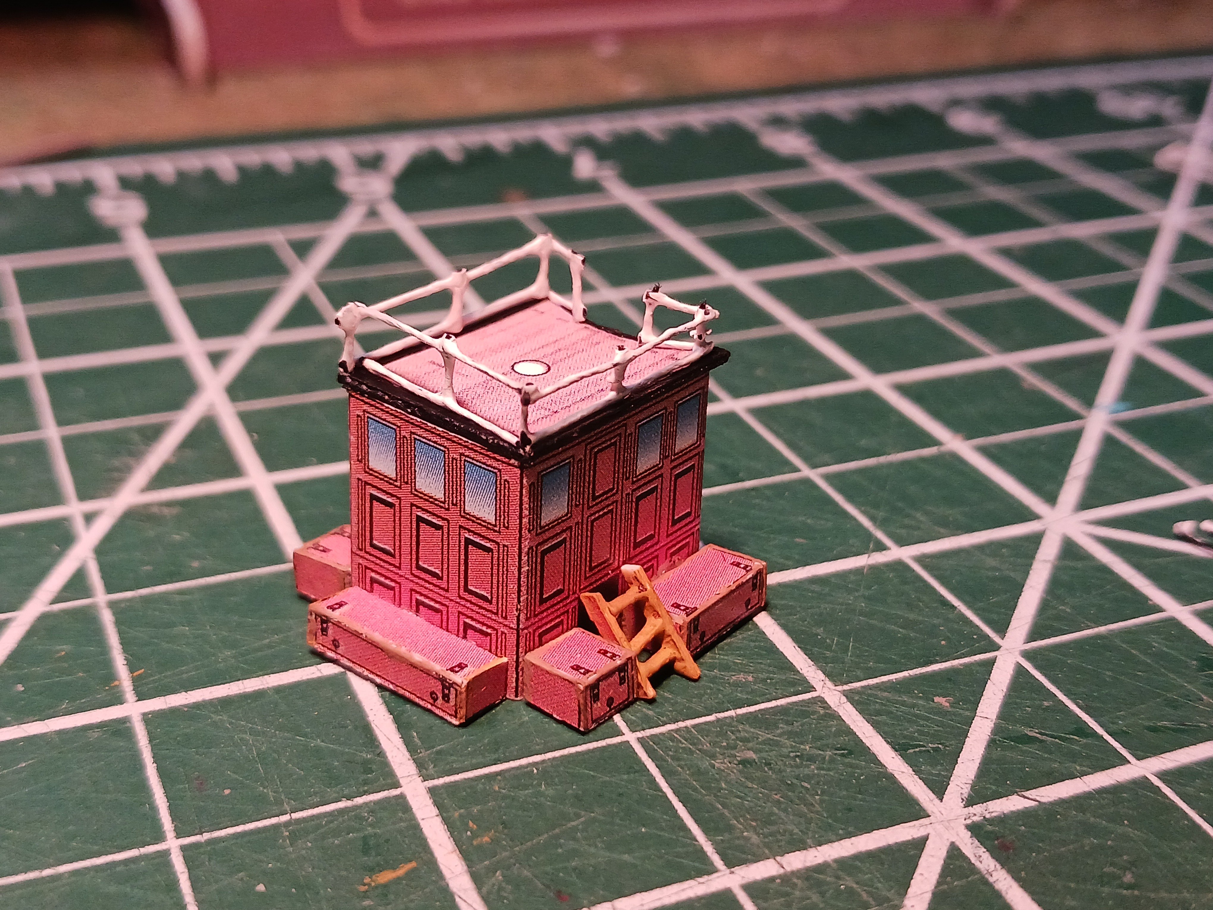
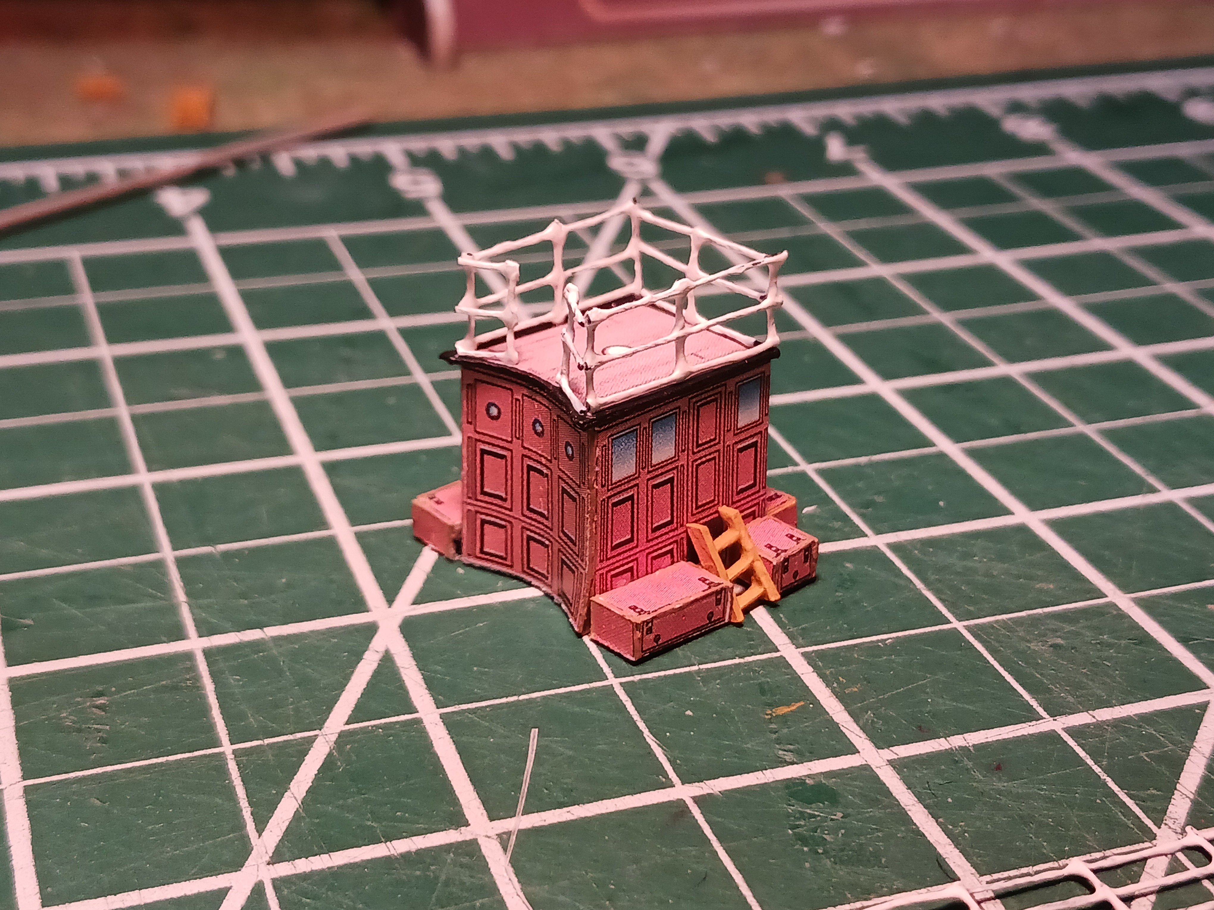
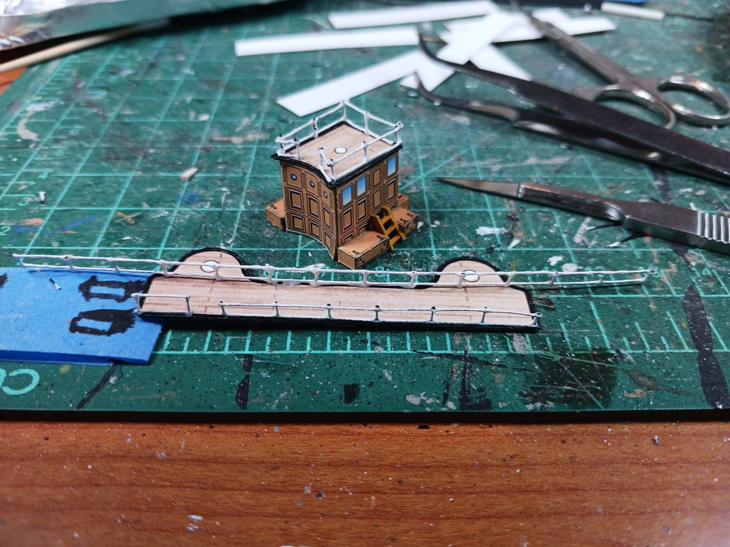
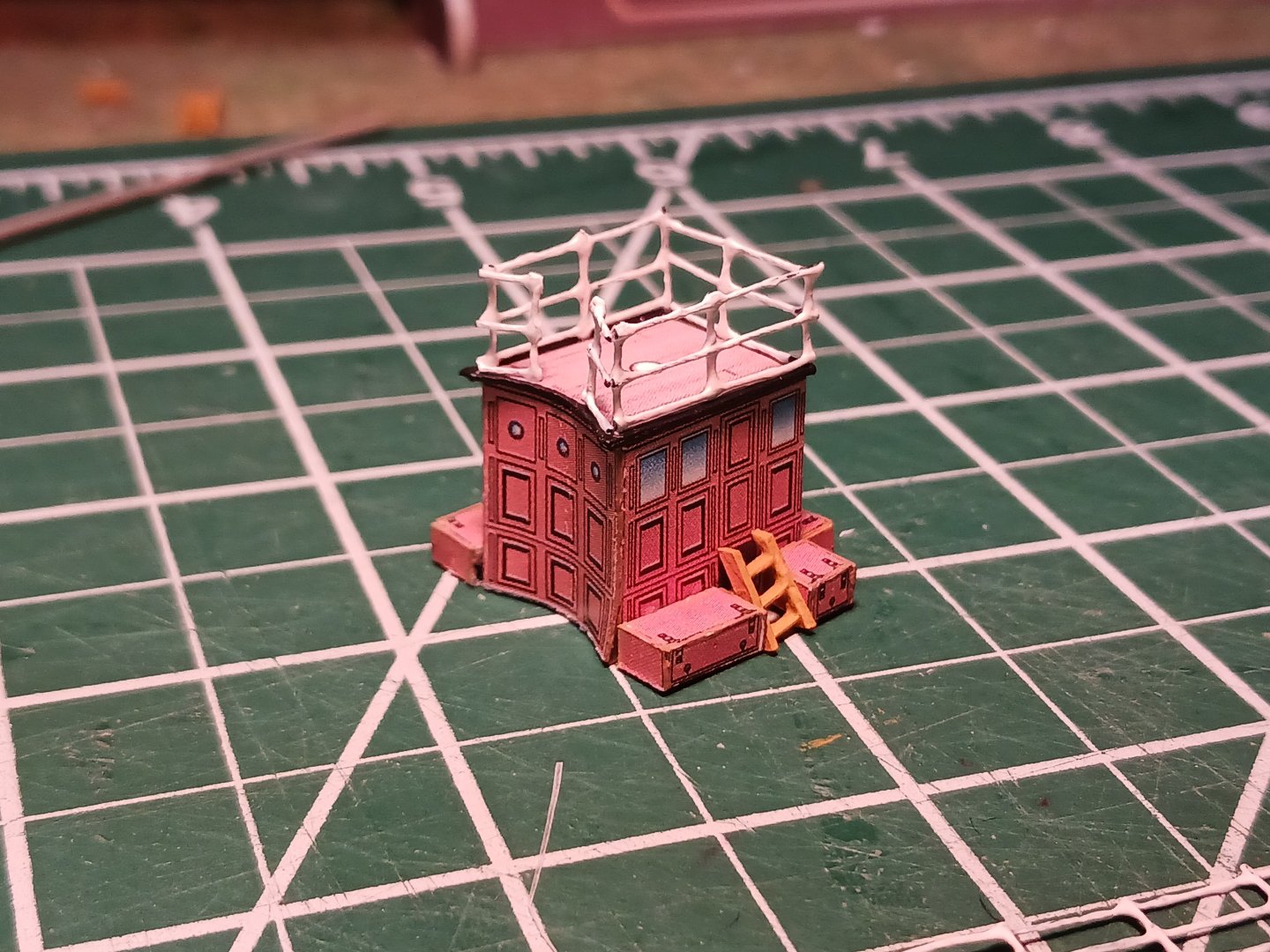
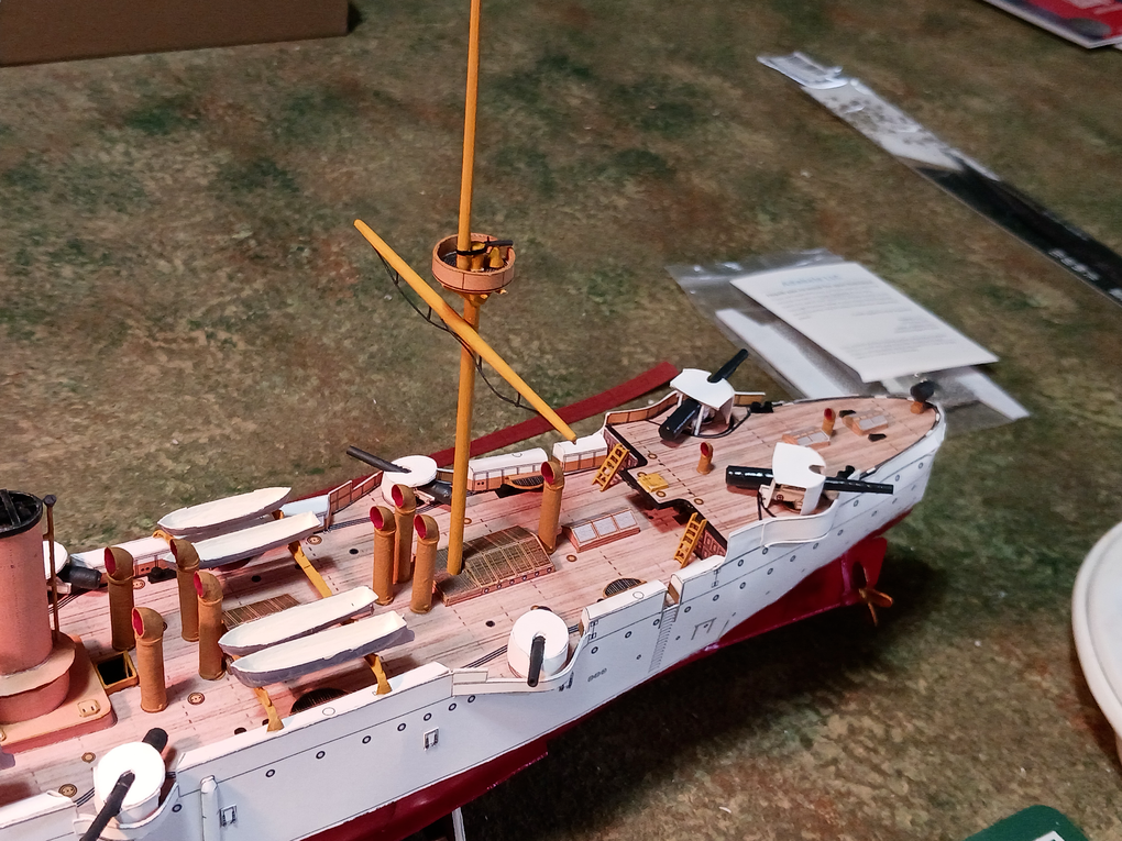
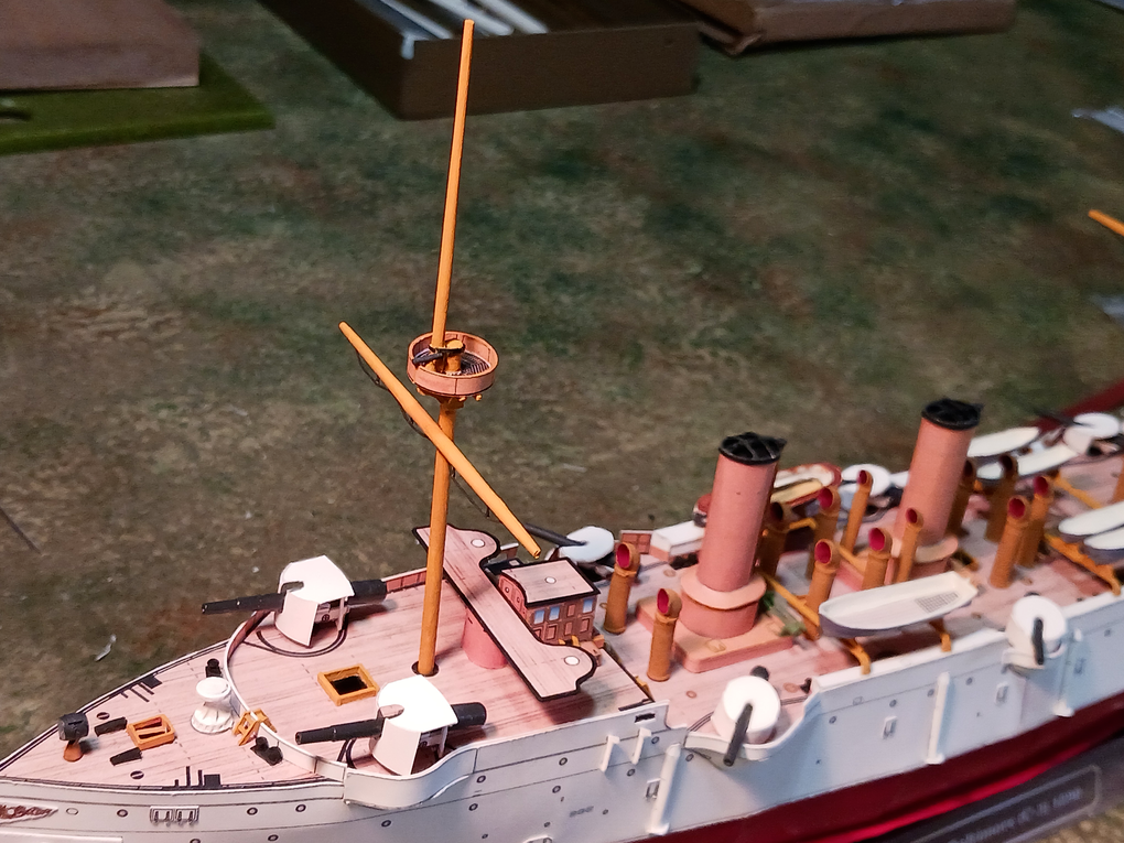
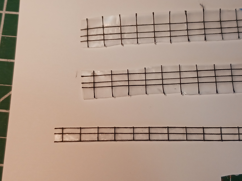
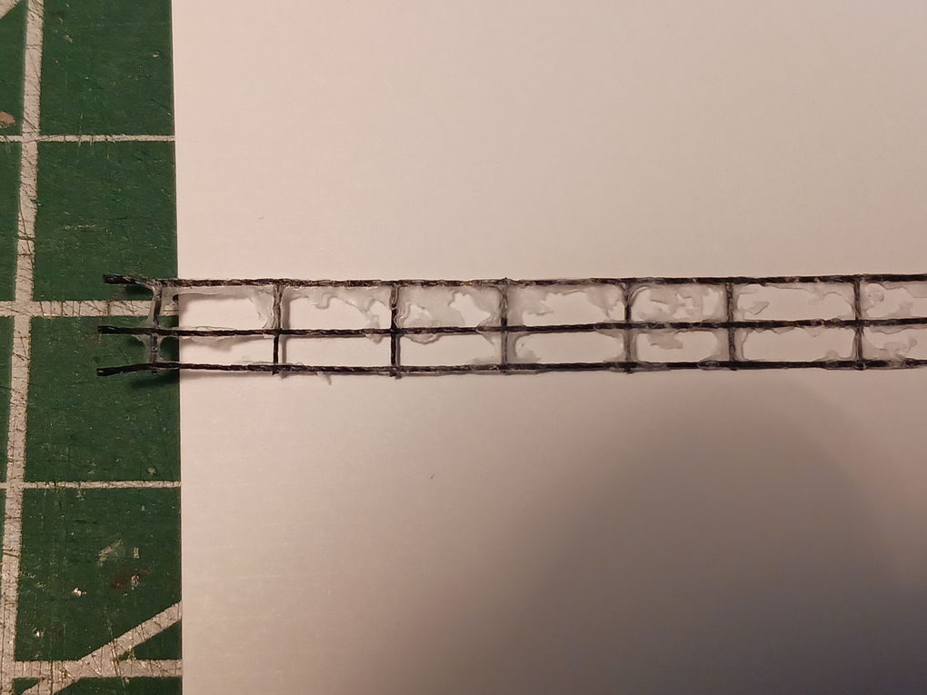
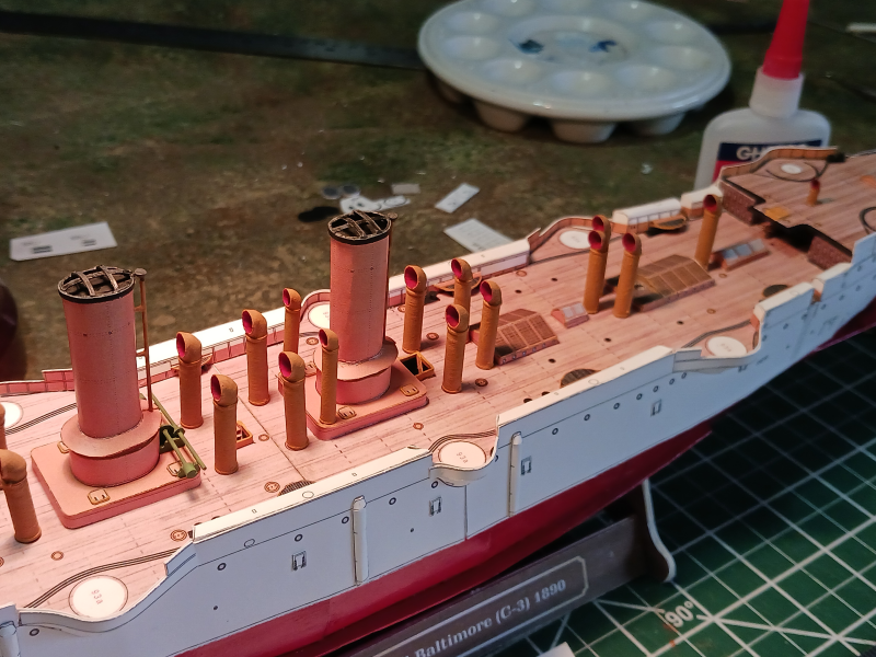
Thanks for the likes, guys. Yep. The raised jig worked much better, SHJ. I tried a number of coatings to try and stiffen things up. The glue, of course, then white gesso, finally tried acrylic floor wax (Future). It all works about the same but I think next time I try railings I'll try the floor wax instead of glue to bind the thread together. It's a lot less viscous than the glue so I think I'll have fewer 'fillets' where the threads cross. Just a couple pictures today. Once I added railings to the pilot house I decided that they looked too tall. It's hard to judge from the photographs of the ship but once I figured a 6 foot all man would be about 9mm in scale I decided to cut the top section of the railing off. Now I think it's slightly too short but I think that's better than being a neck high railing. I plan on using thinner sewing thread to bisect the railing once it's attached to the ship. Then I'll do paint touch ups. Next time I do this I'll use white string! Currently working on adding the railings to the bridge. Curving the railings around the search light platforms will be an interesting challenge.

- 37 replies
-
- 2
-
-
- Baltimore
- heinkel models
- (and 2 more)
-
Any highly detailed model is 'Taunting Fate'. Especially if there are pets or children around.
-
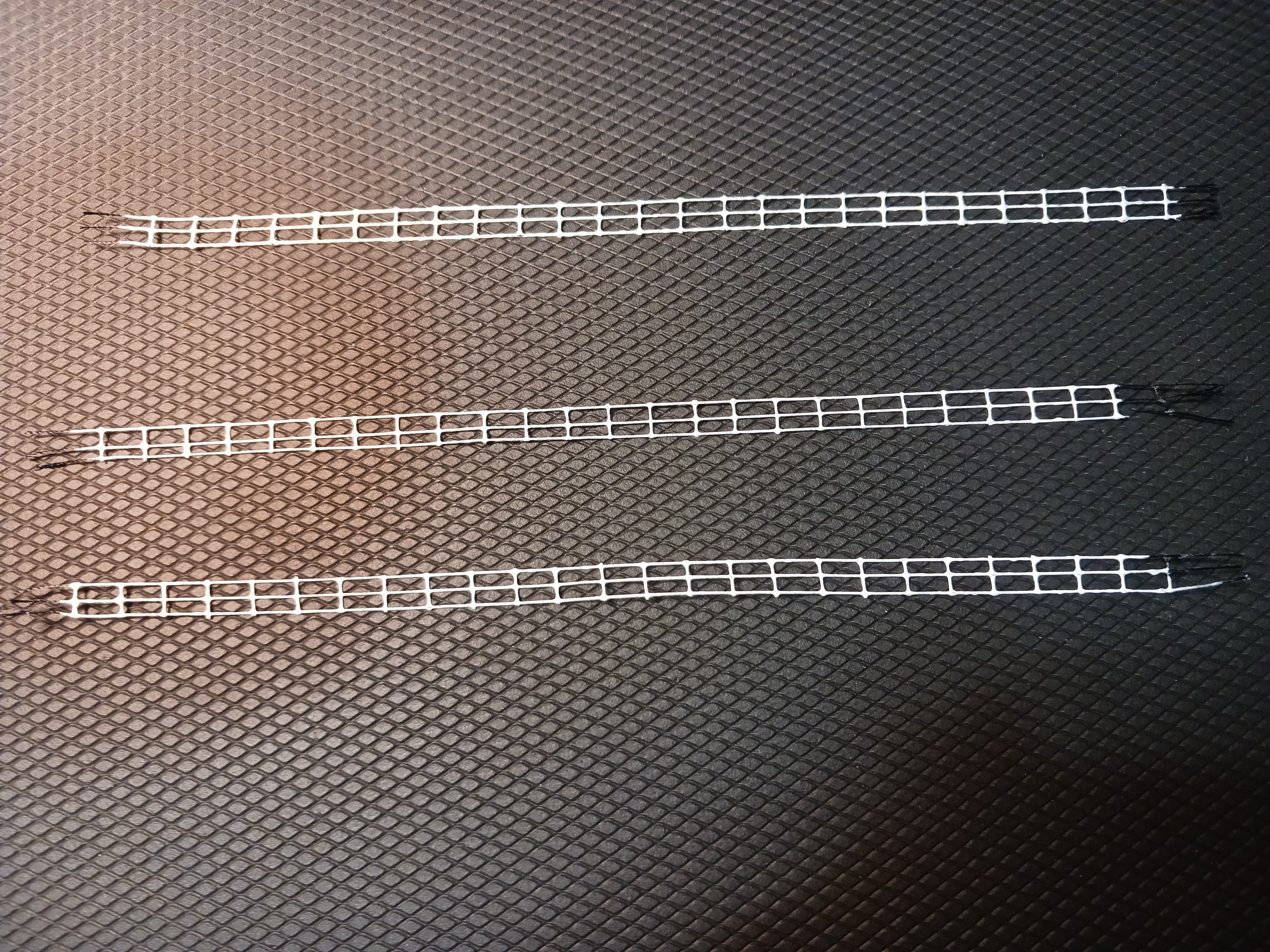
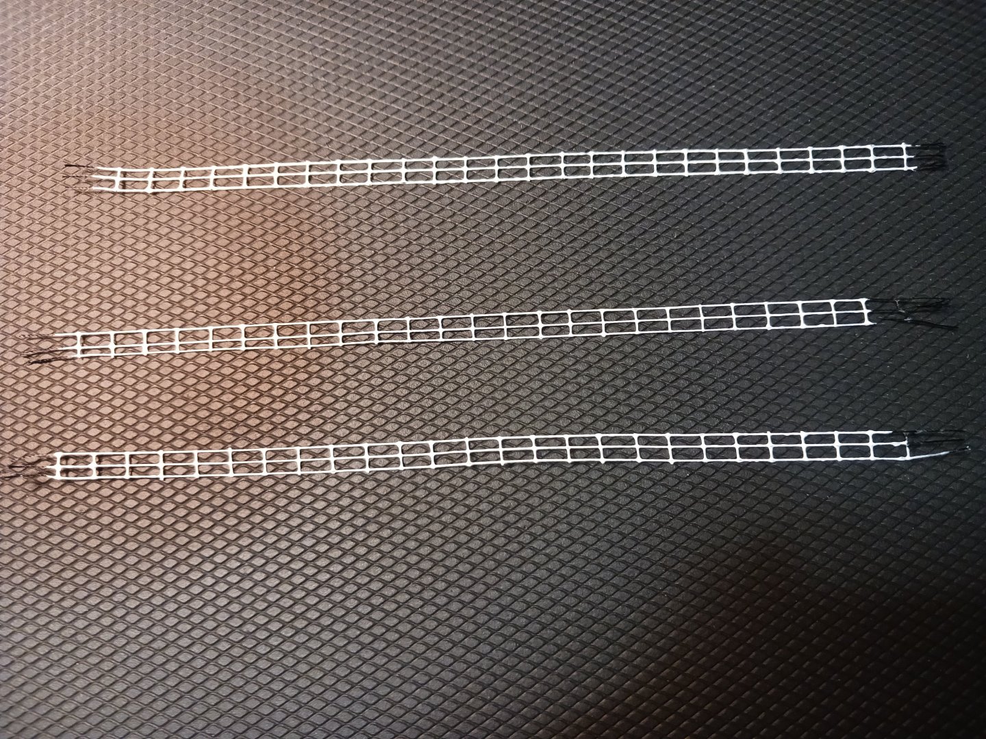
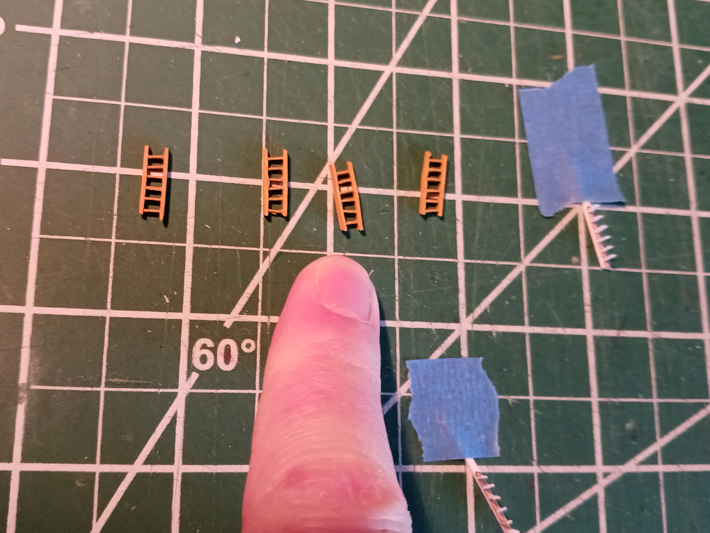
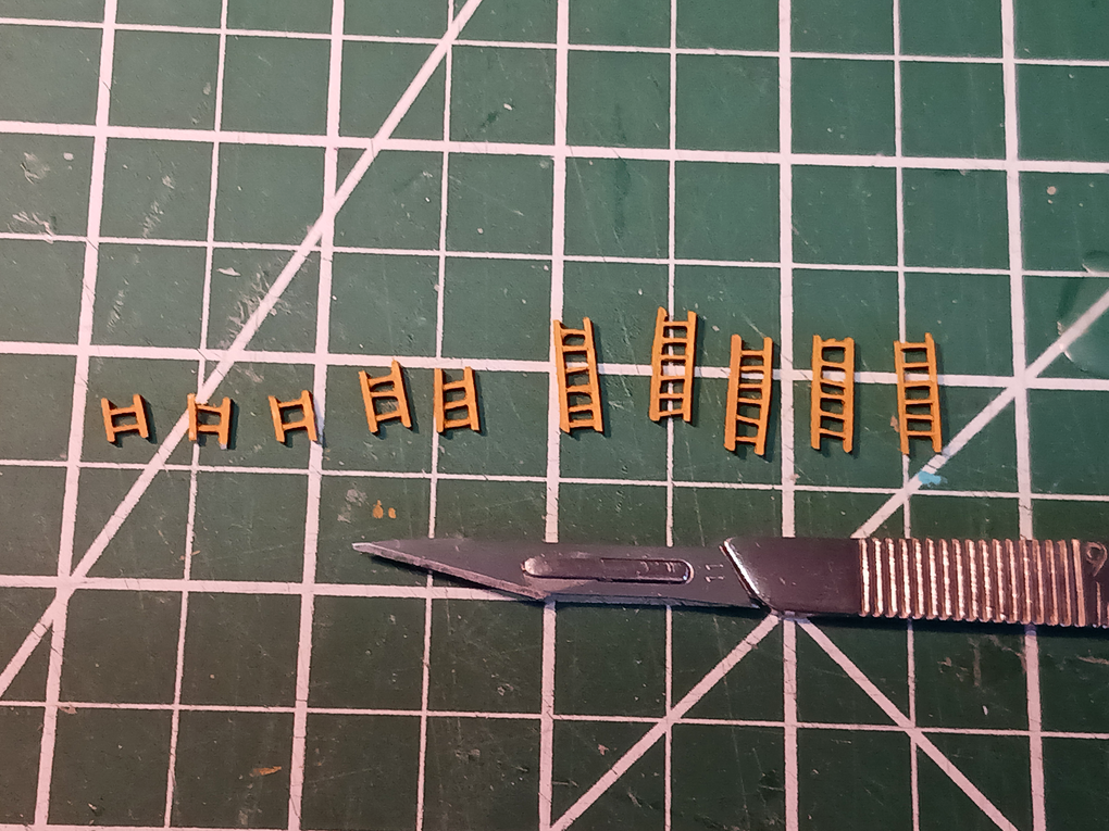
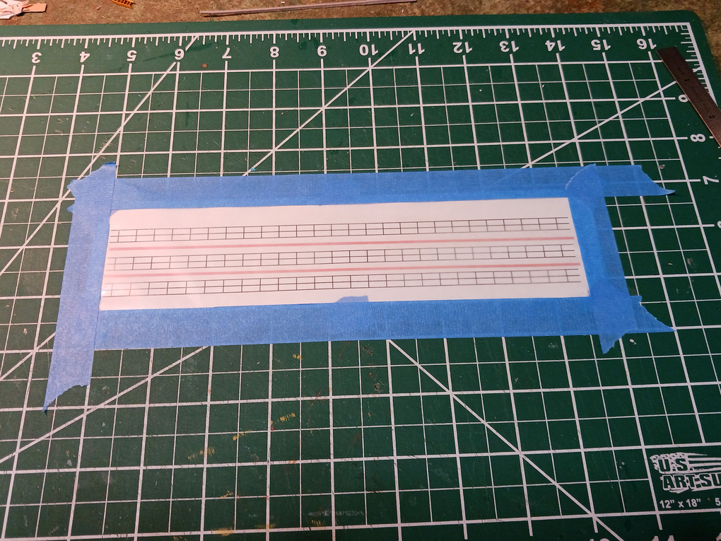
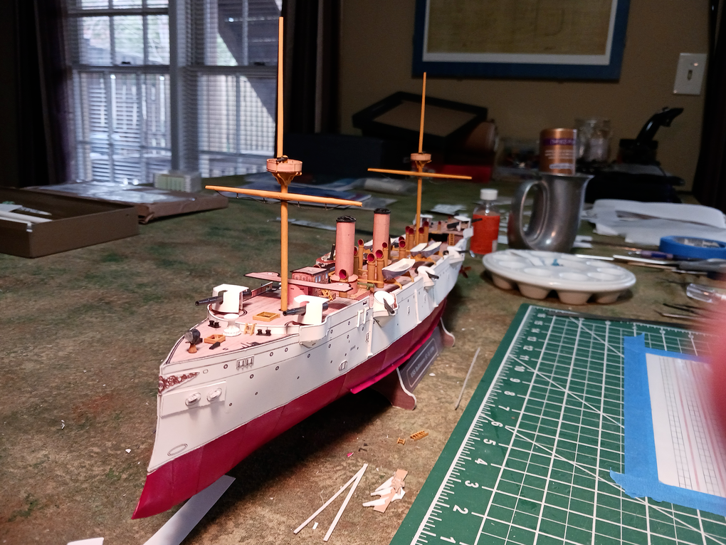
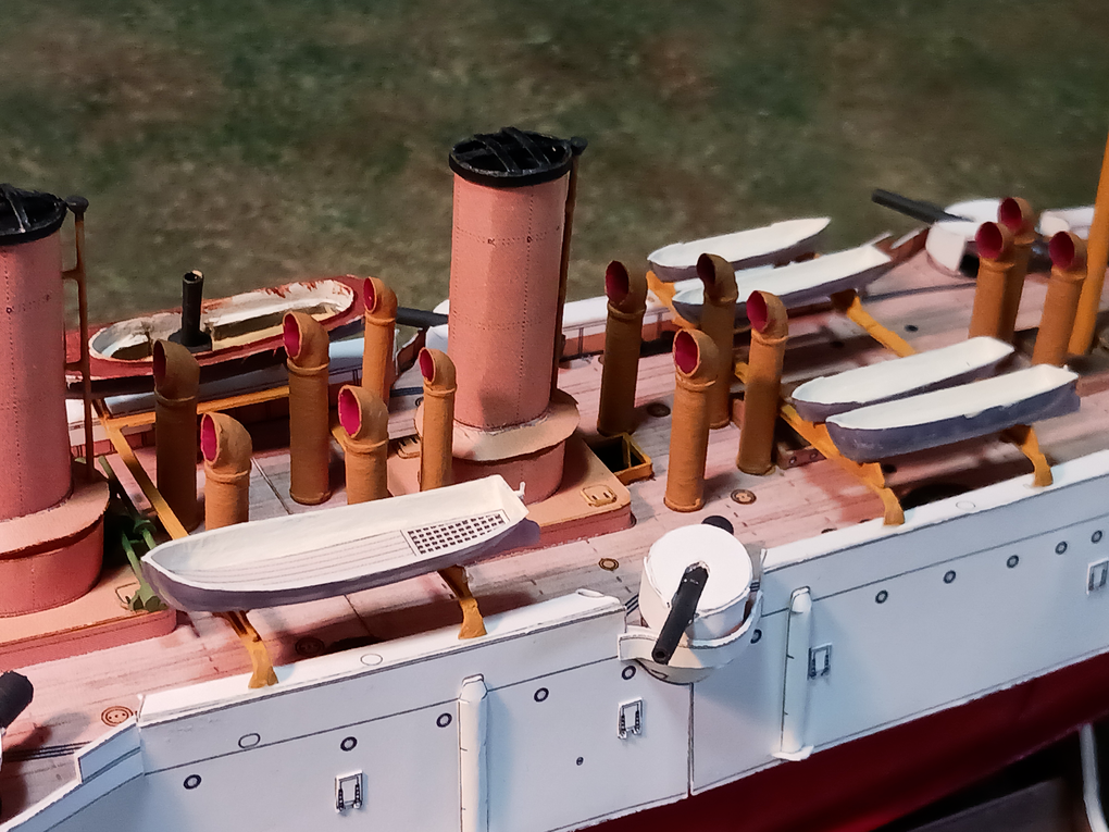
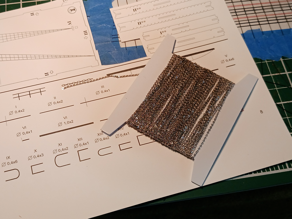
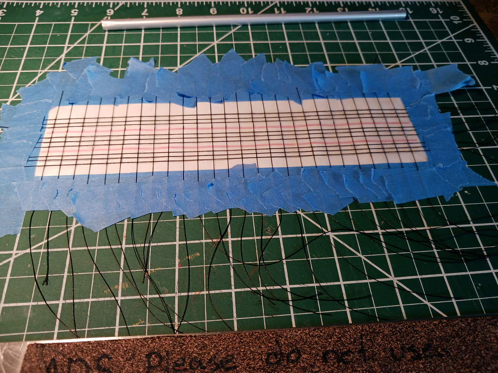
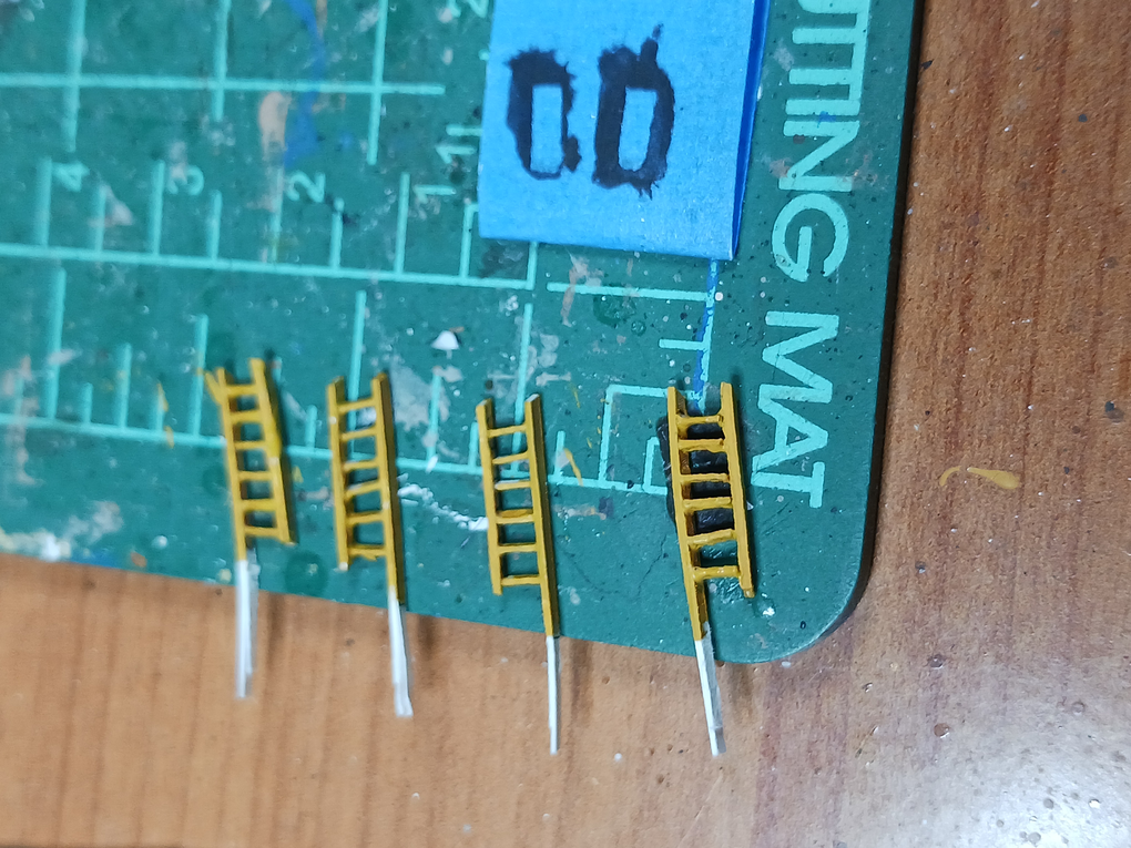
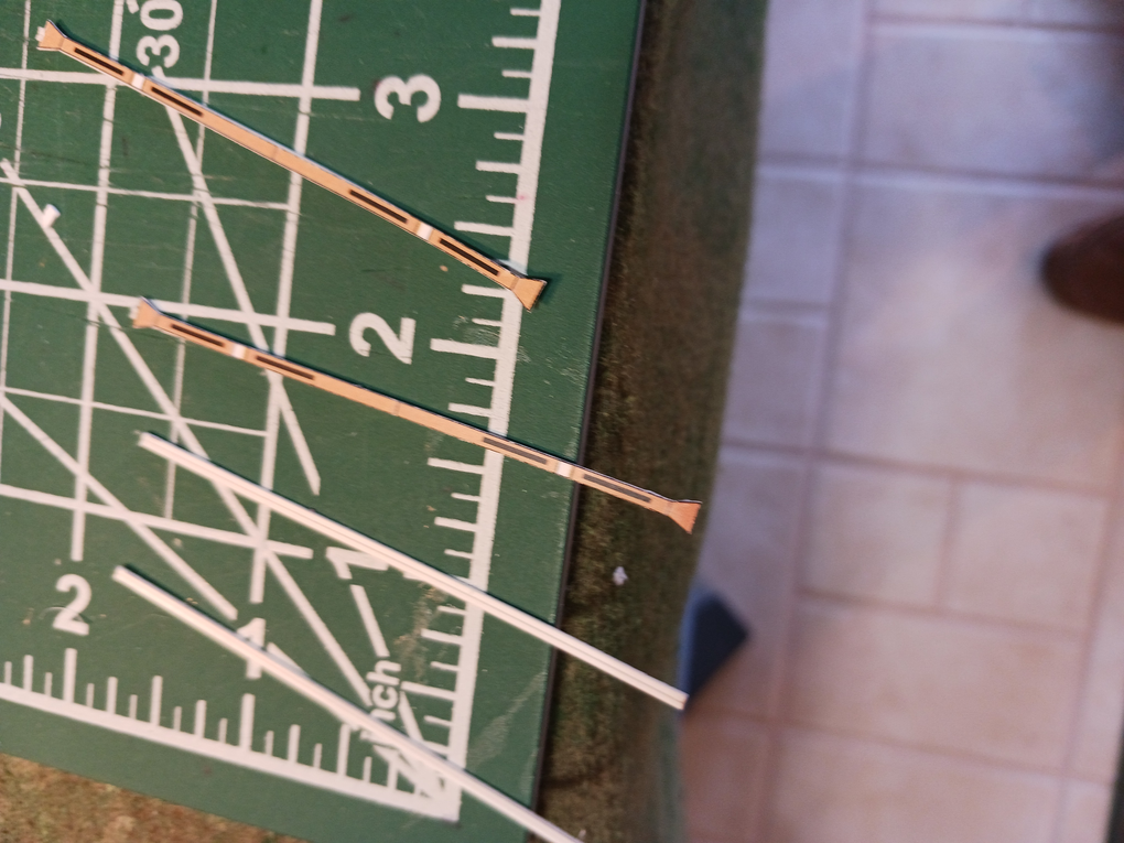
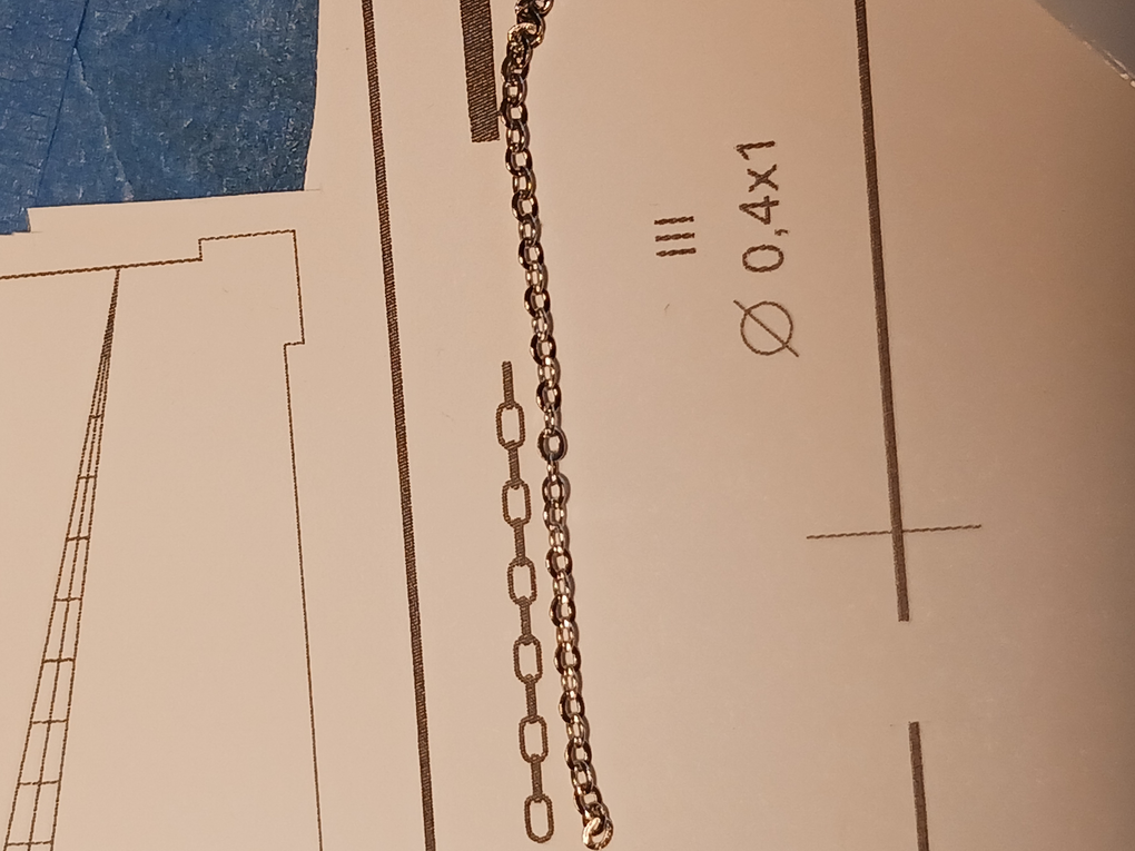
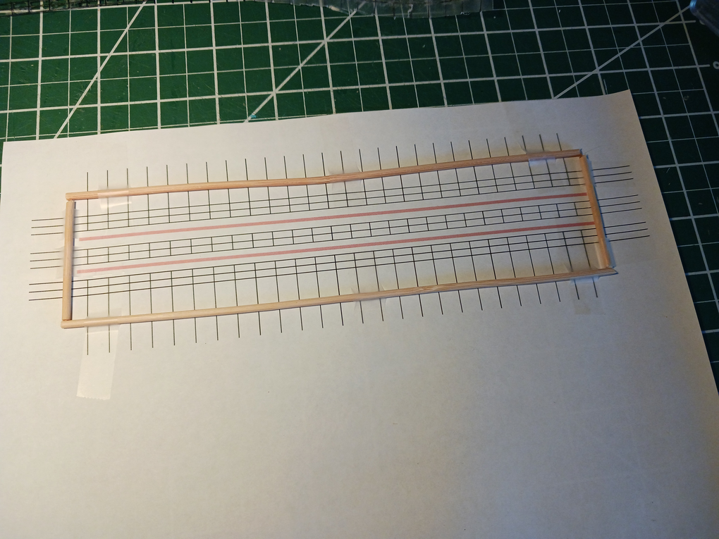
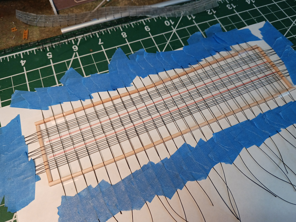
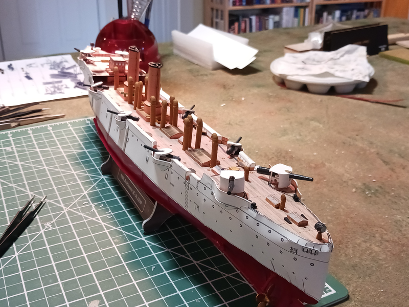
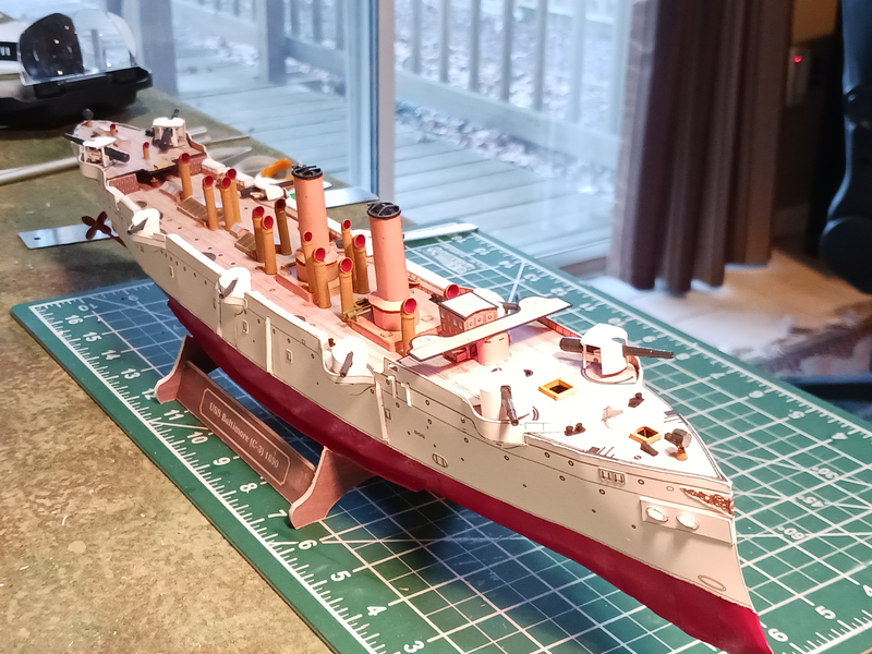
It's been slow going this month as I work through a lot of non-hobby issues. The Admiral is a federal employee; I'm a federal contractor. For several years our plans were to buy a house out-of-state this year and retire in October. So, we've been house hunting and downsizing in hopes that this is still an achievable plan. Of course, given the current administration all our plans may go up in a puff of smoke. Luckily, working on the Baltimore has provided me with something I can control and focus on rather than the uncontrollable future. But what can you do but carry on? Planning for the best but preparing for the worst. Since my last post I've added most of the ladders, the boat racks and both masts to the Baltimore. The ladders are constructed of card. I used strips of styrene sheet for the long span pieces of the boat racks as the card was simply not sturdy enough to remain straight. The lower portions of the masts are plastic tubing while the topmasts are shaved down bamboo skewers. The spars are shaped from the sticks used for cotton swabs which just happened to be the exact right length. The fighting tops are card, the mast trees are a combination of plastic and card. The foot ropes are glue stiffened thread. I started working on the ships boats but decided that I wanted to redesign the 3d printed parts for those and add the interior details. Though, I've not sent them out for printing yet. I did source some jewelry chain for $12 which I think will work well for anchor chain. I'm not sure how to paint it, though. In photographs it appears that the Baltimore's anchor chains--as well as the anchors themselves--were painted white. Lastly, I've been attempting to make railings from glue-stiffened thread. My first attempt was a failure. I graphed out the railings and used a template under waxed paper to lay out the string and coated it with several layers of watered down Aleenes PVC. That approach was almost successful. The string was stiff enough but once I peeled the railings from the wax paper I found glue residue in the gaps between the stanchions and the rails. That's because the thread was laying directly on top of the waxed paper. So, for my second attempt I've raised the thread above the template using bamboo skewers. I haven't applied the glue yet so we'll have to wait to see if this attempt will succeed.
- 37 replies
-
- 3
-
-
- Baltimore
- heinkel models
- (and 2 more)
-
Spray is looking suitably weather beaten. Any more progress?
-
Albatros is looking really good! The finish line is in sight! Go, Phil! Go, Phil, Go, go, go!
-
I seem to recall reading that individual captains could alter the rake of the masts in order to get the best performance from the vessel--basically by altering where the center of force of the sail was located. Is that something that could be done at sea or would it need to be done in port? If so... doesn't that mean that the rake could vary during the life of the vessel?
-
Thank you all for the likes! @Snug Harbor Johnny, it's true that @JerryTodd did some of the 3d printing for me. Turns out he and I flew together in Red Baron 3d many, many years ago, where I knew him by his nom de guerre 'Uhlan'. However, most of the parts were printed by Chris Parker of 'Day of Battle Games'. I've used him for several years for printing 3d ACW ships designed by David Manley. This was my first stab at designing my own *.stl files and Jerry certainly helped me overcome some design issues. I've thought about offering the files as a download but if I do that I want to talk to the model's designer first. I know that WAK offers the pre-printed kit with some optional third party parts and I want to make sure I'm not infringing on anyone's licensing agreements. I'm not sure it's something I have to do from a legal standpoint, but it's certainly the right thing to do. I'm sure that having a model printed and distributed by WAK is much better for the designer than me providing 3rd party *.stl files!
- 37 replies
-
- 3
-
-
-
- Baltimore
- heinkel models
- (and 2 more)
-
Absolutely, yes! Like ancient Egyptian, a lot of meaning in English is derived from context. At least we have vowels!
-
I wonder if the progression from lacing to grommets to wood then iron hanks was primarily driven by how often they needed to be replaced. Hmmm... the growth of technology, I suppose.
-
Yeah... pirates with rapiers... a gentleman's or Musketier's weapon. L'Olannios, probably not. Maybe only to use it as a spit for a baby over a barbecue. Ooops... did I say that out loud?
-
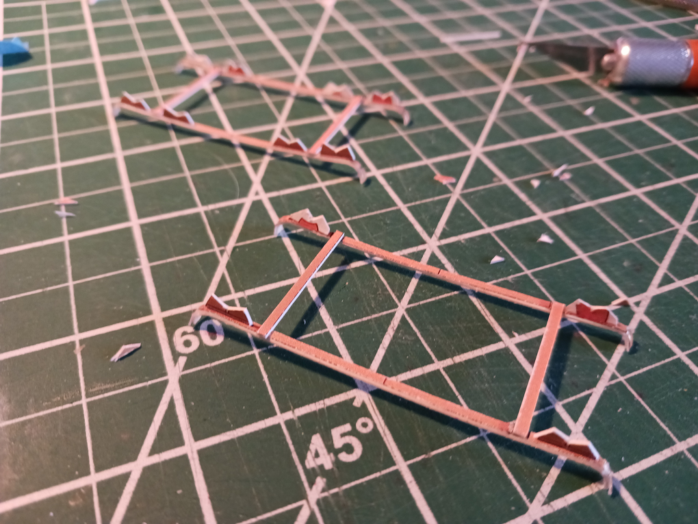
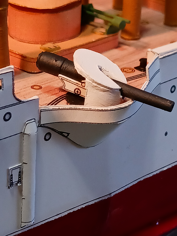
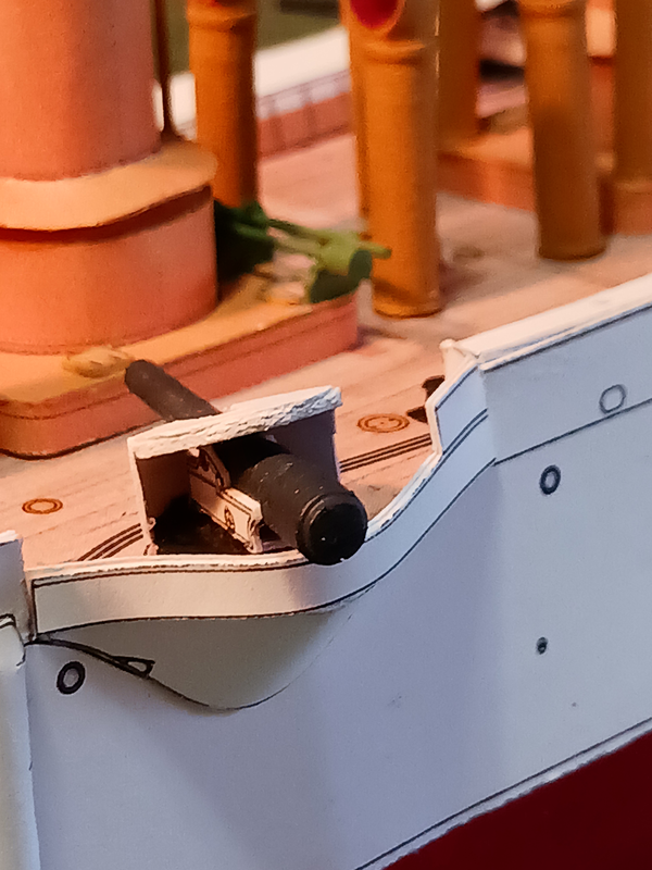
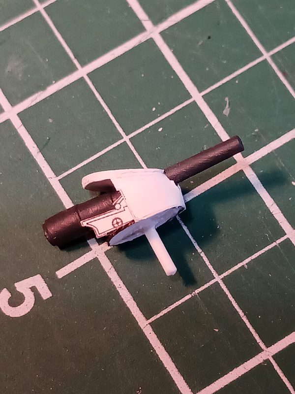
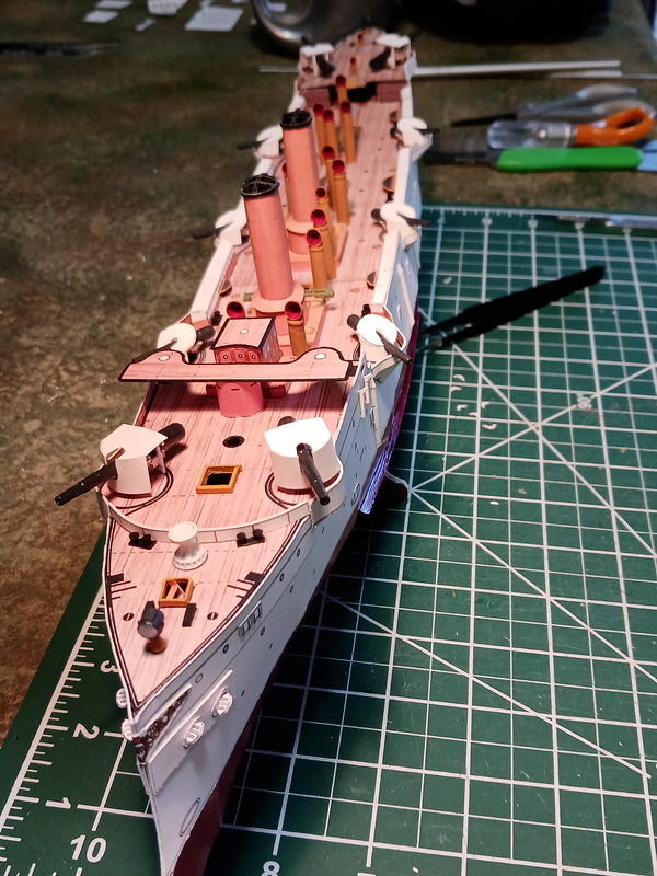
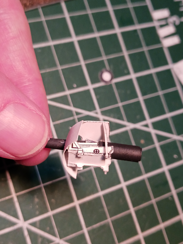
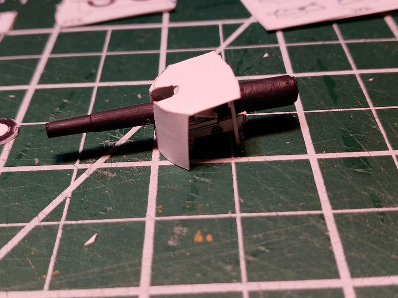
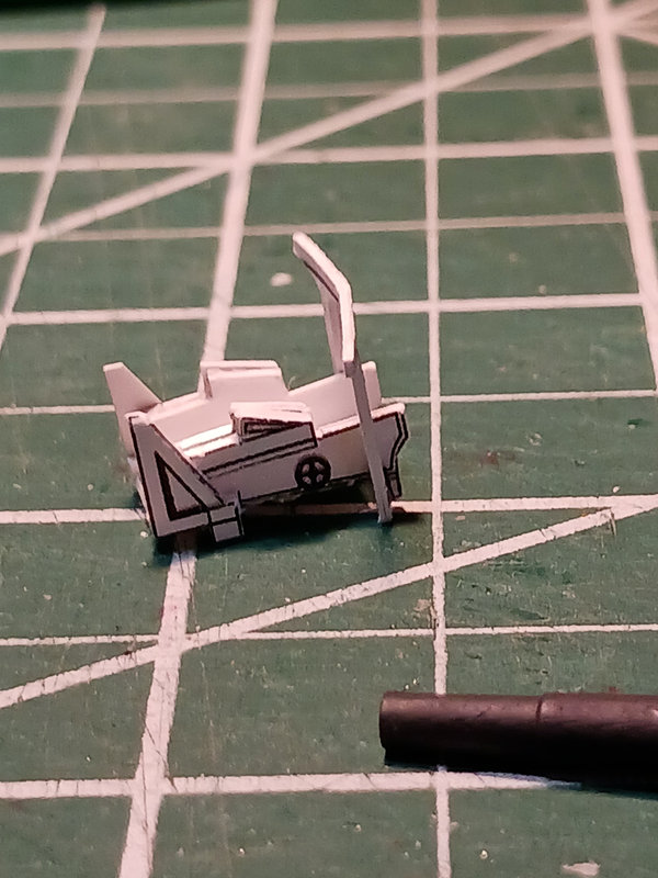
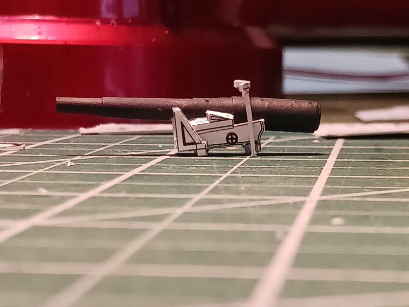
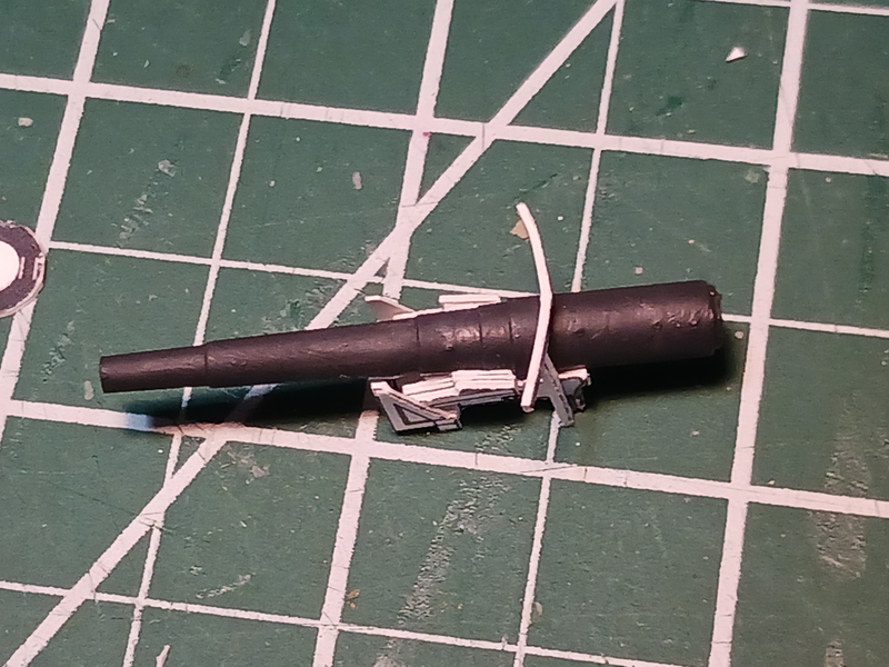
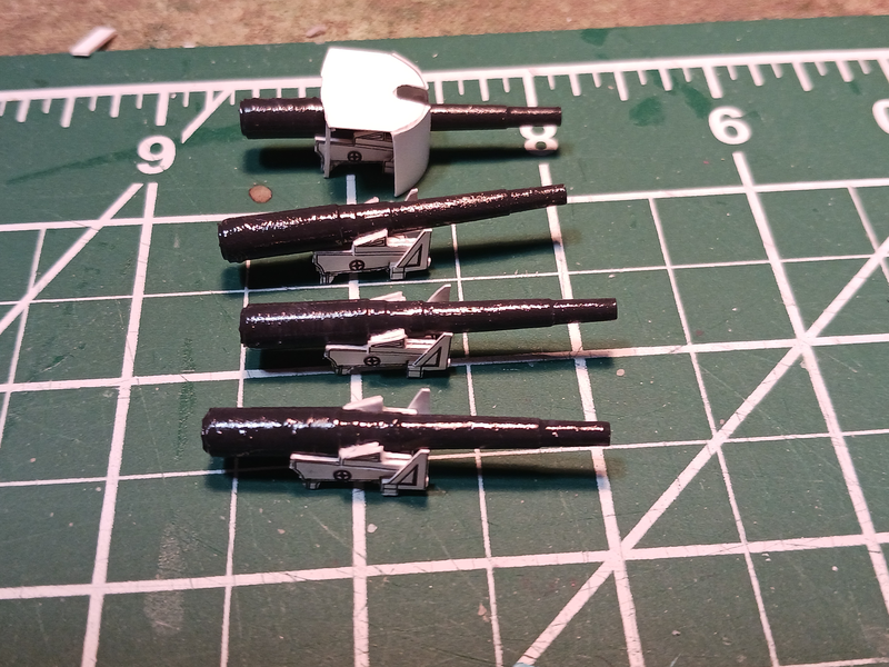
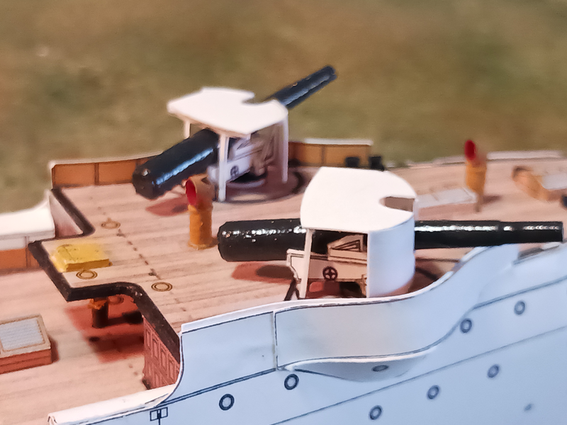
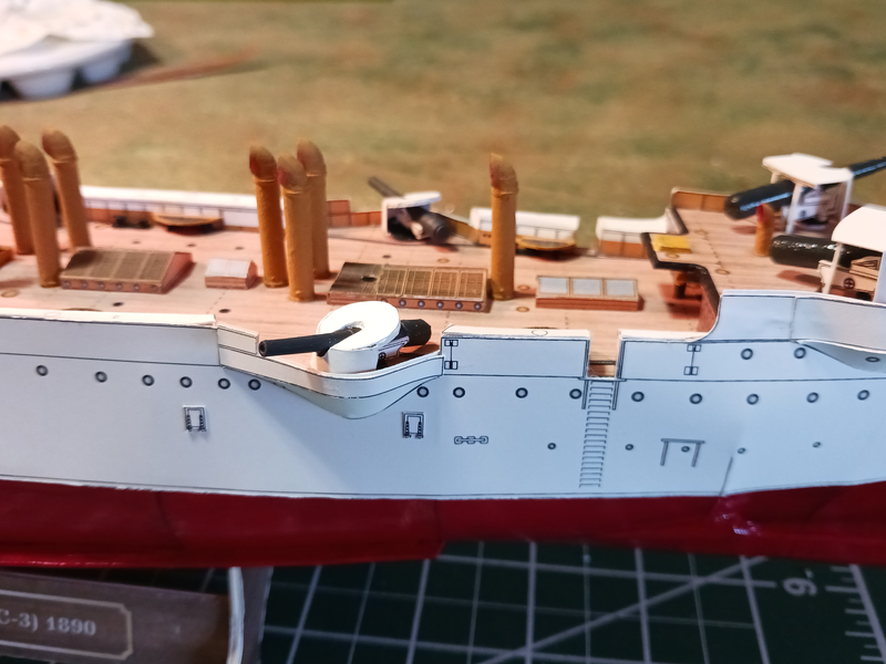
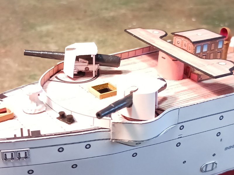
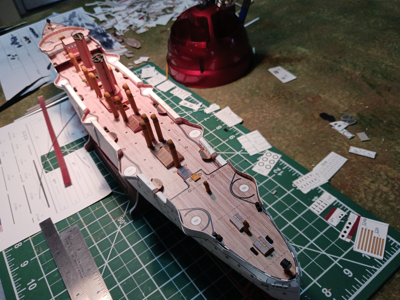
Primary and secondary guns completed! I started with the four 8-inch guns. Construction was straight forward. No issues at all even though some of the structures were quite small. The secondary, 6-inch guns proved more problematic. The front shield had small wings that were supposed to wrap around the tops and then support the top with a straight bar. So, from the top view the front shields would form a 'D' shape with the straight part towards the rear of the gun. I couldn't for the life of me get that to work. The structure was too flimsy for me to be able to attach the roof parts. So I ended up cutting off the offending wings and laminating the roof to 1mm card to give me a surface to glue the front shields to. That meant that the guns on their carriages were a bit too tall to fit so I cut the small legs off the carriages to shorten them. It worked--and unless someone has built this model--probably nobody would ever notice. I also decided to add a plastic pin to the guns and drill holes in the decks for the pin. I haven't decided whether I'll glue the guns in place or not. Right now I rather like the fact that I can rotate the guns.
- 37 replies
-
- 7
-
-
- Baltimore
- heinkel models
- (and 2 more)
-
l'Olonnaise is looking seriously moody, there. Just wondering what type of heinous act he's contemplating. Looking good, though.
-
I'd be surprised if there's anything definitive in regards to the ancient rigging. I suspect your best bet is to study pictures of the Olympias and adapt to a smaller craft. I know I've read Severin's book on the Argo but I don't seem to own it any more. Maybe there are photos of the reproduction about? A quick search uncovered this: https://indigenousboats.blogspot.com/2012/04/how-accurate-was-tim-severins-argo.html .
-
Don't you dare! After all the time and research you've put in to getting this build right you deserve the satisfaction of calling it complete! Besides, you can't be the Godfather of schooner rigging with an unfinished schooner.
-
Thanks, @bear! Your long ship looks great. I think you really elevated the model by adding the nails and removing the dragon head and tail. Looks very realistic. Are you doing a build log on the Argo? I just recently saw that it was available, though I don't know where. It's definitely a model that got my attention. If it requires about the same skill level as the long ship I just might give it a go.
-
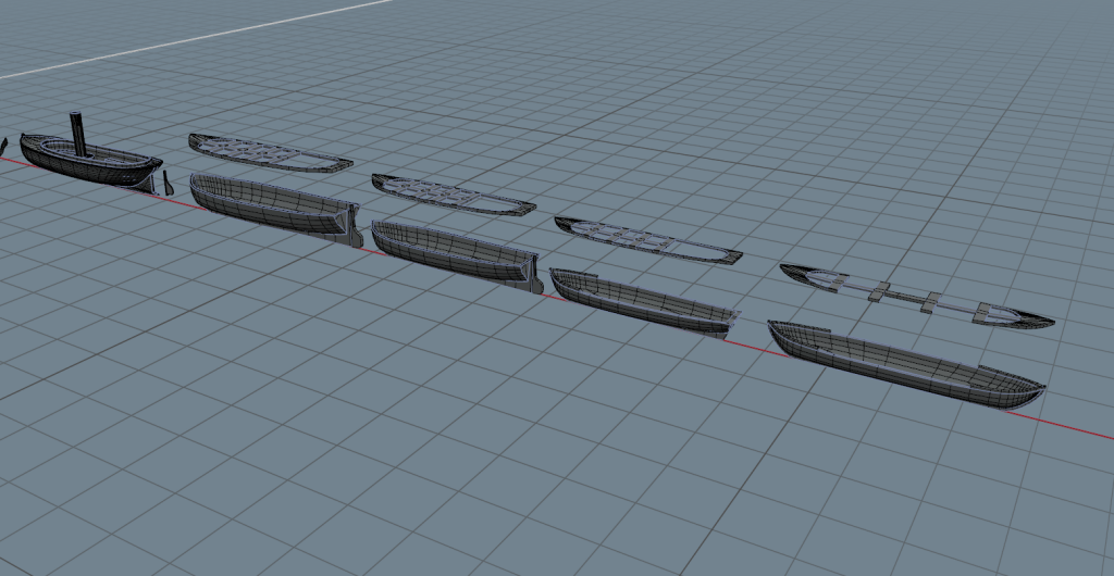
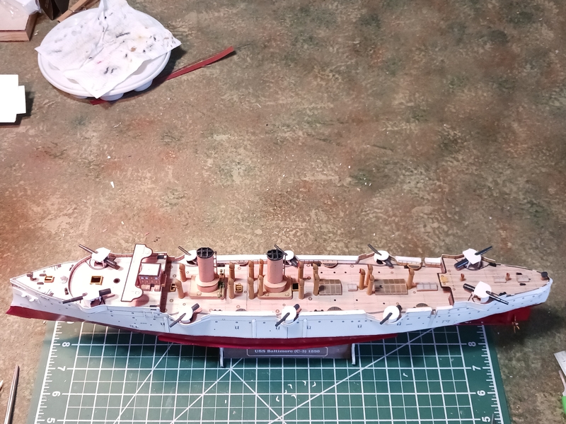
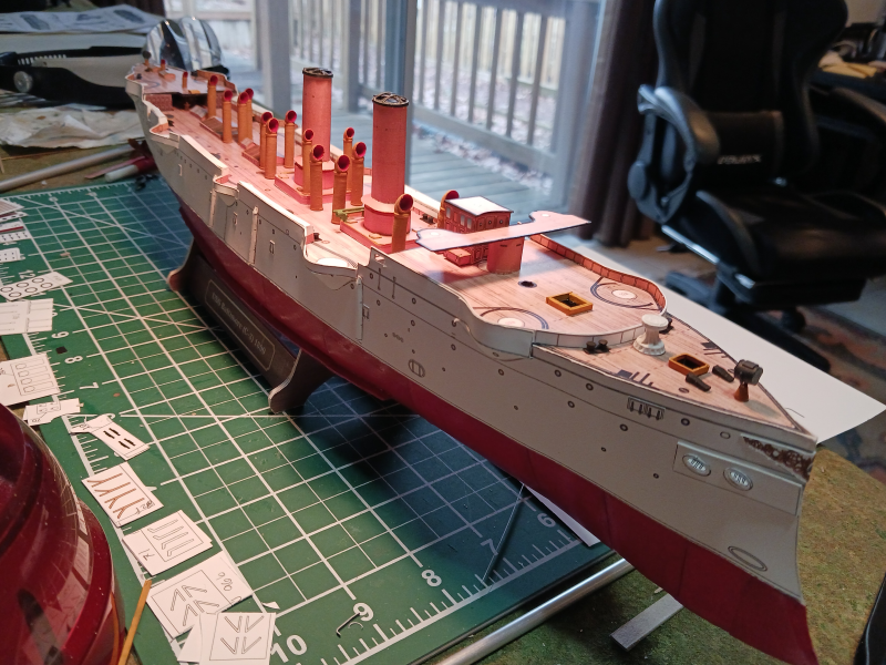
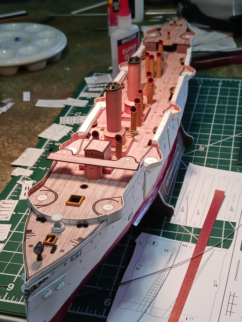
Thanks, everyone! Just a little work completed this week: ventilators and spot lights painted and added. I'm very happy I went with the 3d printed small parts. I'd never be able to make these parts from card. It's beginning to look like a ship! Still debating whether I'm going to attempt the railings or the batteries next. BTW, in the last picture, does anyone know what the little black wedge shaped things are on either side of the gangway? There's also a pair at the stern. I suspect they have something to do with anchor handling but I'm not sure. I do wish the instructions gave part names along with part numbers. While I understand that's tricky in the multi-language international paper-model market it would be nice to learn more of the ship anatomy.
- 37 replies
-
- 5
-
-
- Baltimore
- heinkel models
- (and 2 more)
-
I've got this one in my stash (along with the H L Hunley). Haven't decided if I'm going to build it or not but your results are inspiring.
- 3 replies
-
- 2
-
-
- Turtle
- Heinkel Models
- (and 2 more)
-
Thanks for this build log. I am watching and learning. I think my first scratch built card model is not far off.
-
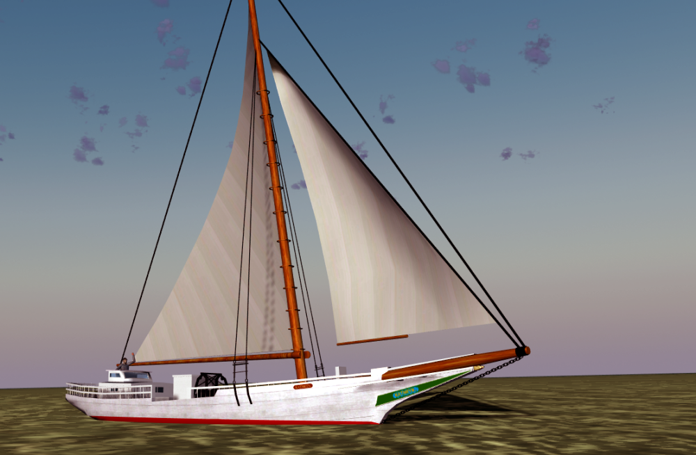
I'm no expert but I'm not sure whoever rigged the Danmark had a solid understanding of how rigging worked. The Blanco de Sal is just bizarre! I've seen blown glass models of ships but never salt.