


wrkempson
-
Posts
288 -
Joined
-
Last visited
Reputation Activity
-

 wrkempson got a reaction from AntonyUK in Fusion 360
So I took the Fusion 360 challenge. Having used Turbocad for years, I found F360 to be fairly straight forward. The hardest part is finding the tool you want and learning the peculiarities of the program. I have done some work in Onshape and found it comparable. It seems to me that anyone willing to put in a bit of time, willing to look at training videos and willing to persevere can learn both F360 and Onshape in a reasonably short time frame. The work flow details differ, but not so much as to make difficult the adapting previous of methods to each program.
Both Onshape and F360 are free cloud based programs. Onshape's free version is fully functional but limits the number of files one can store to 10. Fusion 360 offers the fully functional version for free to hobbyists. You do have to sign up and indicate that you are either a hobbyist or a start up business. The guidelines for signing up are very clear.
I choose to model a 29' Launch in TC and F360 just to compare the two. I was learning F360 from scratch and have done a fair amount or work in TC. The results are appended. Do not get too excited about comparing the renderings since my skills in rendering are quite crude. The point is that each program produces an interesting model. Perhaps I will test out converting the models to 2D drawings at some future date. I should mention that launches were still whole moulded, so there was very little employment of Beziers in these models.
This the the Launch from Fusion 360:
And the same plan in Turbocad v. 19:
Wayne
-
 wrkempson got a reaction from Ben752 in Fusion 360
So I took the Fusion 360 challenge. Having used Turbocad for years, I found F360 to be fairly straight forward. The hardest part is finding the tool you want and learning the peculiarities of the program. I have done some work in Onshape and found it comparable. It seems to me that anyone willing to put in a bit of time, willing to look at training videos and willing to persevere can learn both F360 and Onshape in a reasonably short time frame. The work flow details differ, but not so much as to make difficult the adapting previous of methods to each program.
Both Onshape and F360 are free cloud based programs. Onshape's free version is fully functional but limits the number of files one can store to 10. Fusion 360 offers the fully functional version for free to hobbyists. You do have to sign up and indicate that you are either a hobbyist or a start up business. The guidelines for signing up are very clear.
I choose to model a 29' Launch in TC and F360 just to compare the two. I was learning F360 from scratch and have done a fair amount or work in TC. The results are appended. Do not get too excited about comparing the renderings since my skills in rendering are quite crude. The point is that each program produces an interesting model. Perhaps I will test out converting the models to 2D drawings at some future date. I should mention that launches were still whole moulded, so there was very little employment of Beziers in these models.
This the the Launch from Fusion 360:
And the same plan in Turbocad v. 19:
Wayne
-
 wrkempson got a reaction from Don9of11 in Fusion 360
So I took the Fusion 360 challenge. Having used Turbocad for years, I found F360 to be fairly straight forward. The hardest part is finding the tool you want and learning the peculiarities of the program. I have done some work in Onshape and found it comparable. It seems to me that anyone willing to put in a bit of time, willing to look at training videos and willing to persevere can learn both F360 and Onshape in a reasonably short time frame. The work flow details differ, but not so much as to make difficult the adapting previous of methods to each program.
Both Onshape and F360 are free cloud based programs. Onshape's free version is fully functional but limits the number of files one can store to 10. Fusion 360 offers the fully functional version for free to hobbyists. You do have to sign up and indicate that you are either a hobbyist or a start up business. The guidelines for signing up are very clear.
I choose to model a 29' Launch in TC and F360 just to compare the two. I was learning F360 from scratch and have done a fair amount or work in TC. The results are appended. Do not get too excited about comparing the renderings since my skills in rendering are quite crude. The point is that each program produces an interesting model. Perhaps I will test out converting the models to 2D drawings at some future date. I should mention that launches were still whole moulded, so there was very little employment of Beziers in these models.
This the the Launch from Fusion 360:
And the same plan in Turbocad v. 19:
Wayne
-
 wrkempson got a reaction from herask in Fusion 360
So I took the Fusion 360 challenge. Having used Turbocad for years, I found F360 to be fairly straight forward. The hardest part is finding the tool you want and learning the peculiarities of the program. I have done some work in Onshape and found it comparable. It seems to me that anyone willing to put in a bit of time, willing to look at training videos and willing to persevere can learn both F360 and Onshape in a reasonably short time frame. The work flow details differ, but not so much as to make difficult the adapting previous of methods to each program.
Both Onshape and F360 are free cloud based programs. Onshape's free version is fully functional but limits the number of files one can store to 10. Fusion 360 offers the fully functional version for free to hobbyists. You do have to sign up and indicate that you are either a hobbyist or a start up business. The guidelines for signing up are very clear.
I choose to model a 29' Launch in TC and F360 just to compare the two. I was learning F360 from scratch and have done a fair amount or work in TC. The results are appended. Do not get too excited about comparing the renderings since my skills in rendering are quite crude. The point is that each program produces an interesting model. Perhaps I will test out converting the models to 2D drawings at some future date. I should mention that launches were still whole moulded, so there was very little employment of Beziers in these models.
This the the Launch from Fusion 360:
And the same plan in Turbocad v. 19:
Wayne
-
wrkempson reacted to Ben752 in H.M.S. Atalanta - Drafting my own plans
When I initially started this project, I started down the path creating a 3d model in Fusion following the order of the book. It quickly became apparent that this strategy is not an optimal way of working. However, the work below on the keel is fairly simple and was able to be salvaged before I shited to following a construction order closer to what is described in Steel.
The process used is as follows:
1. Under a new component create separate sketches for the fore, aft and a middle timber of the keel.
2. The top plane worked well to construct the aft and middle sketches as it lends itself well to a extrude along the Y axis.
Because the mid keel components are repeated, I repeated the component using the rectangular pattern feature. This gives me a reference edge to project in the fore timber sketch with the added bonus of propagating tweaks forward.
3. On the fore timber, I constructed the sketch using the left side plane as it allows for projecting the arcs of the stem to model the the boxing. Whenever possible, I"ve used projections off of one of my "master" sketches to allow for propagation of changes to the bodies that model the timbers.
4. To create the simplified boxing joint I created the sketch for the lower stem on the left plane, extruded on one face left face to 1/2 the thickness and used the combine/cut option on the fore keel. Then did the same on the other side but make the fore keel the cutting tool.
-
wrkempson reacted to Ben752 in H.M.S. Atalanta - Drafting my own plans
Good day everyone,
I've recently moved to Edinburgh for work. My personal effects are somewhere in the middle of the atlantic (above water hopefully). This has given me time to focus on planning my first scratch build, the H.M.S. Atalanta.
I've selected this ship due to the wealth knowledge in the TFFM series, availability of contemporary plans from Admiralty models, historical plans and many build logs. The hope is that with all of this information, it will give me enough information to stumble through the creation of plans using CAD and construction of the ship to a high level of quality.
I'm using Fusion 360 as my CAD program due to it's excellent price (free for hobbyist), professional quality and integrated t-spline, anlysis tools, parametric modeling features and CAM support.
I have made several false starts on the plans as Fusion is stew relatively new to me. One of the trickiest things is getting a good scan of the draughts into fusion and scaled. When you can zoom in to miniscule details of the draughts it becomes apparent how warped and skewed they are.
One technique that I've found useful in fusion, is that when using the "attach canvas" that if you first create a component, you can then duplicate the component and translate it. This is quite welcomed after you go through the laborious process of aligning and rescaling the draught.
To start off, I've made a considerable effort to follow the practices outlined in Steele. The dimensions have been sourced through a contract I found for the HMS Hornet at the RMG and the TFFM books. When there is a discrepancy I've sided with the TFFM as the books are my guide. My effort is to not trace but rather draft using a combination of traditional methods and 3d approaches.
Given this, the sheer plan is first up. In Fusion, I've created "primary" sketches for each major major plan with the exception of more detailed aspects (following the order of Steel lends itself well to this approach). For more detailed areas, I then create a separate sketch and project or intersect the references needed. Fusion prefers this approach as it runs faster and easier to apply constraints and such. For starters, here are my sheer sketches.
Below is the sketch in edit mode so the dimensions are visible (when zoomed it the dimensions are more manageable).
I've found using custom parameters exceptionally useful for cataloging scantlings and the source reference material I used.
-
wrkempson reacted to BANYAN in TUrboCAD-LTE vs TurboCAD vs Draftsight
Hi Nathan. I used TurboCAD 2016 Pro to develop the plans for my HMCSS Victoria build (ongoing). TC 2016 allowed me to import either a PDF (PDF/Underlay manger) or raster image files (BMP, JPG etc), which if put on their own layer, aligned and scaled then locked, allow you to trace what you need - note they are separate tools in TC. The TC 2018 blurb states that the image manager has been improved in 2018 but my reading to date suggests that this is only to allow multiple image file import rather than interaction between the image and drawing layers (that is selection of parts of the image to convert/use in the CAD drawing). I would really like to know more about the TC 2018 image manager if anyone has any experience with it?
In my drawings I have imported some large photographs and lithographs, and have had up to as many as 10 underlying images - visibility turned on and off as required - as background reference images (once scaled). However, I have experienced some issues with the images disappearing occasionally (the image holder remains) requiring reloading of the image. That said, I think that this is a problem of my own making by deleting or moving the parent file (as they are linked) by default. This could be overcome by embedding the image (an option in TC Image manger) but your drawing/TC file will become very large - or do not rename. move or delete your parent image files :).
I have drawn up my plans with the wrong techniques with literally thousands of elements/entities as I am a self-taught absolute amateur - this resulted in me drawing every item individually (including each treenail head) instead of using blocks and symbols etc - lesson learned for next time . So the files could have been much smaller allowing some image embedding if required. Overall I have found that the image import, alignment and scaling for using as a background to trace in TC, is a relatively straight forward process once you get to grips with it.
cheers
Pat
-
wrkempson reacted to Don9of11 in Fusion 360
I use Onshape exclusively for my ship design and woodshop projects. There are tons of tutorials to get you started. If you are already familiar with 3D modeling you'll pick up on things pretty quickly if not the tutorials are very good. There is no software to download. You can signup for a free account or paid subscription. I've inserts a few screen shots. Hope this helps.
-
wrkempson reacted to herask in Swan class 3D model in progress
just a small reminder we're still alive and kicking. rigging phase draws ever nearer...:-))
-
 wrkempson got a reaction from reklein in Deck plank detail
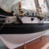
In theory this arrangement keeps the planks for sliding alongside one another resulting in a stiffer longitudinal structure. In the hold of USS Constellation the ceiling planking has square cutouts across the seams into which a square block is inserted in order to stiffen the hull as well. The attached photo shows these openings, some of which have had the blocks fall out. Indicated in red are examples of an empty and a filled opening. Other instances are apparent as well.
Wayne
-
 wrkempson got a reaction from Mark P in Deck plank detail
In theory this arrangement keeps the planks for sliding alongside one another resulting in a stiffer longitudinal structure. In the hold of USS Constellation the ceiling planking has square cutouts across the seams into which a square block is inserted in order to stiffen the hull as well. The attached photo shows these openings, some of which have had the blocks fall out. Indicated in red are examples of an empty and a filled opening. Other instances are apparent as well.
Wayne
-
 wrkempson got a reaction from mtaylor in Deck plank detail
In theory this arrangement keeps the planks for sliding alongside one another resulting in a stiffer longitudinal structure. In the hold of USS Constellation the ceiling planking has square cutouts across the seams into which a square block is inserted in order to stiffen the hull as well. The attached photo shows these openings, some of which have had the blocks fall out. Indicated in red are examples of an empty and a filled opening. Other instances are apparent as well.
Wayne
-
wrkempson got a reaction from mtaylor in TUrboCAD-LTE vs TurboCAD vs Draftsight
TurboCad 2017 Pro allows pdf files to be inserted as underlay objects, more or less as raster images. The resolution is not the greatest but it does allow it. You can also load your pdf in Acrobat, take a screen capture and convert in Paint to a jpg. The resolution is a little better that way.
Actually, you may want to search the web with "pdf to jpg" and you will find several apps that convert pdf's to jpg's. I am under the impression that Acrobat Pro has a utility for converting to jpg's. I have no need for such, but they are there for your consideration.
Wayne
-
wrkempson got a reaction from mtaylor in HMS Bellona 1760 by SJSoane - Scale 1:64 - English 74-gun - as designed
Trying to muscle the errant middle into place sounds like something I would try to do. That should warn you that it may be a questionable move. It seems to me that a buckle in the middle indicates a snying of the ends. This happens to me (all the time when I was laying on the hull planking) due to poor spiling of the plank. Before you apply the force, maybe one more time with a careful spiling might be interesting.
I say this as one whose skill falls far below yours, so I offer this more as a question than as advice.
Wayne
-
wrkempson reacted to druxey in HMS Bellona 1760 by SJSoane - Scale 1:64 - English 74-gun - as designed
Glad all went well, Mark! You have a beautiful workshop view....
-
 wrkempson got a reaction from paulsutcliffe in HMS Bellona 1760 by SJSoane - Scale 1:64 - English 74-gun - as designed
Trying to muscle the errant middle into place sounds like something I would try to do. That should warn you that it may be a questionable move. It seems to me that a buckle in the middle indicates a snying of the ends. This happens to me (all the time when I was laying on the hull planking) due to poor spiling of the plank. Before you apply the force, maybe one more time with a careful spiling might be interesting.
I say this as one whose skill falls far below yours, so I offer this more as a question than as advice.
Wayne
-
 wrkempson got a reaction from druxey in HMS Bellona 1760 by SJSoane - Scale 1:64 - English 74-gun - as designed
Trying to muscle the errant middle into place sounds like something I would try to do. That should warn you that it may be a questionable move. It seems to me that a buckle in the middle indicates a snying of the ends. This happens to me (all the time when I was laying on the hull planking) due to poor spiling of the plank. Before you apply the force, maybe one more time with a careful spiling might be interesting.
I say this as one whose skill falls far below yours, so I offer this more as a question than as advice.
Wayne
-
wrkempson reacted to SJSoane in 74-gun ship by Gaetan Bordeleau - 1:24
Hi Gaetan,
I have been thinking about your projector experiment. I have attached a diagram showing what the issues might be.
In the first diagram, showing the project and ship hull from the side, if the light source is a single point, then the image lines will radiate away from the source. An image at X is projected to a greater Y on the projected surface, but the image will be an even greater Z at the hull.
The second diagram shows the setup in plan. If the light source creates parallel rays, the image on the projected surface will be accurate, even around the curve at the bow. But if the light source is a single point, as in the third diagram, the distance on the hull at Z will be greater than the distance at Y on the projected surface. and the curve at the bow will not be accurate.
You could avoid this problem if you could take each point on the projected surface, and then project it onto the hull exactly at right angles to the projected surface. Maybe this could be done with your laser beam.
Just some thoughts in your very interesting experiment!
Mark
-
wrkempson reacted to yamsterman in WASHINGTON GALLEY by yamsterman - 1/48 scale - POF
HI ALL
DECK BEAMS ARE FINALLY FINISHED!!!
STARTED WORK ON THE WATERWAYS FROM HOLLY , FORWARD BITS FROM REDWOOD FOR A BIT OF CONTRAST.
HATCH FRAMES MADE FROM BOXWOOD......GRATINGS YET TOO BE MADE
TIMBERS CUT FROM STEAMED PEAR FOR INNER PLANKING AND HOLLY FOR THE DECKS.
THATS ALL FOR NOW..
CHEERS....MICK
-
 wrkempson got a reaction from Canute in Color of ratlines
Also for what it is worth, colors do not behave on small models the same way as on full size ships. Here we are getting into the area of scale colors. I would observe that a very light colored ratline on a black (maybe) shroud will pop out to the eye on the model. An even worse mistake that I have committed is to use a line that is too large. The scale size of the ratline should not be exceeded, but may be lessened if anything. When I look at photos of full rigged ships, the ratlines are barely visible unless one makes the effort to see them. I don't think the ratline should call attention to itself. As always, the usual disclaimer.
Wayne
-
 wrkempson got a reaction from Tigerdvr in Color of ratlines
Also for what it is worth, colors do not behave on small models the same way as on full size ships. Here we are getting into the area of scale colors. I would observe that a very light colored ratline on a black (maybe) shroud will pop out to the eye on the model. An even worse mistake that I have committed is to use a line that is too large. The scale size of the ratline should not be exceeded, but may be lessened if anything. When I look at photos of full rigged ships, the ratlines are barely visible unless one makes the effort to see them. I don't think the ratline should call attention to itself. As always, the usual disclaimer.
Wayne
-
 wrkempson got a reaction from Matrim in Color of ratlines
Also for what it is worth, colors do not behave on small models the same way as on full size ships. Here we are getting into the area of scale colors. I would observe that a very light colored ratline on a black (maybe) shroud will pop out to the eye on the model. An even worse mistake that I have committed is to use a line that is too large. The scale size of the ratline should not be exceeded, but may be lessened if anything. When I look at photos of full rigged ships, the ratlines are barely visible unless one makes the effort to see them. I don't think the ratline should call attention to itself. As always, the usual disclaimer.
Wayne
-
wrkempson got a reaction from mtaylor in Color of ratlines
Also for what it is worth, colors do not behave on small models the same way as on full size ships. Here we are getting into the area of scale colors. I would observe that a very light colored ratline on a black (maybe) shroud will pop out to the eye on the model. An even worse mistake that I have committed is to use a line that is too large. The scale size of the ratline should not be exceeded, but may be lessened if anything. When I look at photos of full rigged ships, the ratlines are barely visible unless one makes the effort to see them. I don't think the ratline should call attention to itself. As always, the usual disclaimer.
Wayne
-
 wrkempson got a reaction from Chuck Seiler in Color of ratlines
Also for what it is worth, colors do not behave on small models the same way as on full size ships. Here we are getting into the area of scale colors. I would observe that a very light colored ratline on a black (maybe) shroud will pop out to the eye on the model. An even worse mistake that I have committed is to use a line that is too large. The scale size of the ratline should not be exceeded, but may be lessened if anything. When I look at photos of full rigged ships, the ratlines are barely visible unless one makes the effort to see them. I don't think the ratline should call attention to itself. As always, the usual disclaimer.
Wayne
-
wrkempson got a reaction from druxey in Color of ratlines
Also for what it is worth, colors do not behave on small models the same way as on full size ships. Here we are getting into the area of scale colors. I would observe that a very light colored ratline on a black (maybe) shroud will pop out to the eye on the model. An even worse mistake that I have committed is to use a line that is too large. The scale size of the ratline should not be exceeded, but may be lessened if anything. When I look at photos of full rigged ships, the ratlines are barely visible unless one makes the effort to see them. I don't think the ratline should call attention to itself. As always, the usual disclaimer.
Wayne