Modeler12
-
Posts
1,716 -
Joined
-
Last visited
Content Type
Profiles
Forums
Gallery
Events
Everything posted by Modeler12
-
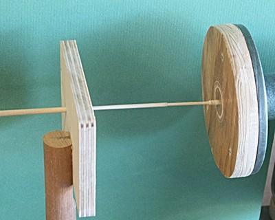
To take the last idea one step further, I can see that a simple support for the end of the dowel would give you less wobble and more control. The picture below was taken when I did my masts and spars on an old Shopsmith, but I can see using a support clamped in a vise could work in a pinch. In my case below I also was able to use a center support but that is not necessary. The plate was stationary and the hole in this plate was just a fraction larger then the dowel and with reasonable care of not forcing the filing and sanding, it worked fine.

-

Using a drill press for other operations.
Modeler12 replied to Modeler12's topic in Modeling tools and Workshop Equipment
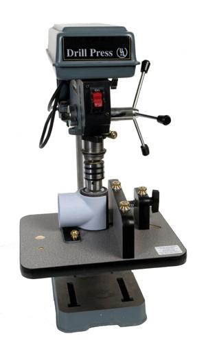
Thanks Dave for posting these pictures. I took a look at this unit and found the picture below. I am curious what the three brass knobs to the right of the drum are for. I can see that the one on the far right is to hold the micro screw in position, but what about the two on top of the fence? Do they clamp the fence down to the table? And if so, there must be a slot in the table??? Now that I look a bit closer, it seems the one in front is stationary and the one in the back slides in a curved slot to make the thickness adjustments. Right? I assume also that the drum runs pretty true without any wobble.
-
Using a drill press for other operations.
Modeler12 replied to Modeler12's topic in Modeling tools and Workshop Equipment
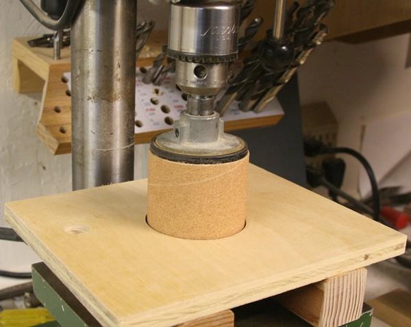
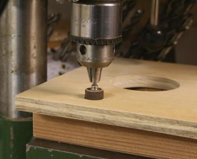
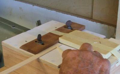
I did something similar, Snowmans. Below are some pictures of my drillpress setup for drum sanding. The larger drum is from my Shopsmith and is 2 3/8 inch diameter. The smaller one is a Dremel drum at ½ inch. I made the platform using two pieces of 2x2 and some ½ inch plywood. It is held to the drillpress table from underneath with two hex-head screw; so it can be removed quite quickly. You can see two holes which are in an arc (the post is the centerline). Thus I can simply rotate the table to change from one drum to the other (after replacing one for the other, of course). Later I may add another one to the right of the large opening. One nice usage for this kind of setup is to touch up the edges of laser cut parts. I think we all know that the thicker bulkhead parts, for example, have a slight bevel to the edge. That is because the laser beam looses power as it goes through the material and the back side is sometimes barely cut. These drums can take care of cleaning this up very quickly and give me a square edge.

-
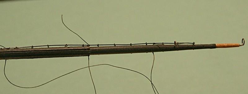
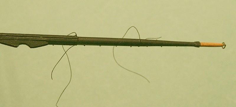
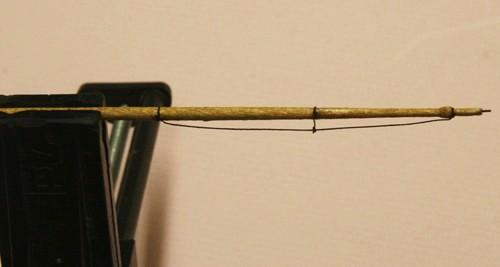
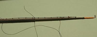
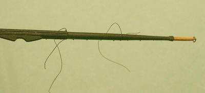
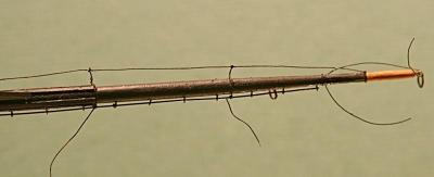
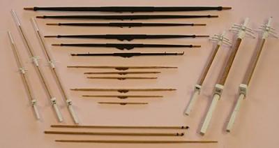
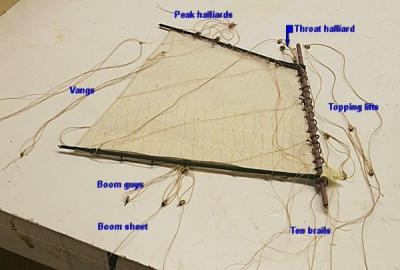
After the rehash above I am now working on the 12 spars. I have added jackstays to the bottom six and footropes to all. Jackstays are the rods that run on top of the spars and are held in place by lots of eyebolts. The sails would be laced to them and they also served for the men to hold onto as they stood on the footropes. ‘One hand for the man and one for the ship’. The footropes were tied to these jackstays as well. I used .010” rope dyed with the ebony color. Starting with the vertical stirrups, I would lace and CA glue the horizontal foot rope to these and the end. A small section of footrope was also added to the very tip of the spars. They are referred to as Flemish Horses. Bottom view This is the spar turned upside down and before trimming the ends of the footropes. It was the position I used to add footropes. The end of the spars and further inboard are some large loops. They would be used to hold studding booms to the spars. I will not be using them (except for the booms stored on the channels next to the hull).

-
Jim, I assume that the dories can be removed easily while you continue building. I found that with my Conny I damaged some outside pieces while doing a lot of deck work. For any future builds I will take care of things in a more logical order to prevent that from being a problem You are being watched my friend
-
Jeff it is good to see your progress. As I look at all your pictures, it brings back memories of my build. You are doing a great job on the difficult bow section. Are you planning to do the carving out of styrene as Bob suggested? I have not tried to do mine yet. You might also keep in mind that Bob forgot to add the extension blocks for the hawse pipes. They are intended to prevent the anchor chains from damaging the rails. I'll keep watching.
-
Another Rope Walk
Modeler12 replied to michael mott's topic in Rope Making/Ropewalks's Rope Materials and parts resources
Micheal you did a nice job of explaining how you designed and built your ropewalk. Impressive (including the large shop you have). For those who are interested here is a video of how it works. This design differs from the other types that use gears for twisting the three (or four) strands. Obviously the video type is rather crude but it shows the principal. -
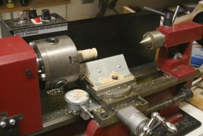
Same here. I made a small tool rest on my mini lathe and these chisels work great for small jobs. The fellow who sold them to me caustioned me about the 1/8 gouge. 'It is easy to break', was his comment. He obviously works with the big ones for turning bowls, etc. The tool rest was made of wood with a sheet metal section for the chisels to rest on. This is a prototype and I want to make another out of solid aluminum. Notice also that I moved the control panels from the front to the back. That allowed me install a dial indicator for the lateral travel (not shown here). I also made a cam operated clamp for the tail stock. You can see the steel rod in the back that activates the cam and clamp. Jim thanks for your help about inserting pictures within the text of these posts.
-
What is your favorite hand tool(s)??
Modeler12 replied to Modeler12's topic in Modeling tools and Workshop Equipment
How to sharpen tools is a bit of a controversial subject, but Ron you might be interested in the following video. http://www.finewoodworking.com/how-to/video/how-to-hone-a-chisel.aspx Don't worry about all those stones the fellow talks about. Two of them will be plenty. I do use a couple of stones in a wooden box that have been around for many years. But what I really like for small cutters is an Eze-lap, a small diamond coated 'file' that gives me an instant edge (even on #11 Exacto blades and other carving tools). I have a couple in the drawer right in front of me at the work bench and I can sharpen an Exacto blade faster than replacing it. Plus I will have a sharper edge than a new blade offers. Check out the following: http://eze-lap.com/woodworking_shop_machine_use/hone-stone/ Now if you really want to get involved with the refining process check out http://www.owdman.co.uk/howto/howto.htm But that should be enough. PS Your avatar reminds me of an early Rembrandt. You could have been one of his models. -
Just to try this let me do the following: Our hero Then there are some of us who were confused: Hero number two. End of try.


-
Thanks Dan. I tried this and it works. I was getting nowhere before. Of course I was able to add pictures with the Attach File but did not realize that you can than also insert this in the text section. Note to Ray. You have to type text first, then insert the picture as Dan showed. Then you can add text underneath the picture you just inserted and continue with more text after (perhaps) hitting the enter key.
-
Dave feel free to use what ever you want from my site. If there are any questions let me know. The web site has my contact information on the main page. Earlier there was a lot of information about the threads to use in making rope and I used some of that. In addition there were a lot of suggestions about deying the rope. I touched on that a bit also. Knex is similar to Logo blocks but it is more advanced and, in my opinion, a great way for youngsters to put mechanical structure together. It has lots of pieces that include gears and electric motors. The gears and shafts I used fit my needs just fine.
-
Using a drill press for other operations.
Modeler12 replied to Modeler12's topic in Modeling tools and Workshop Equipment
Before someone asks me about my 'Shopsmith mini table saw' let me explain. The pictures below show my crude setup that really works quite well for small jobs. It uses a four inch diameter saw blade from Thurston. I need to make some refinements to control the width better and instead of the hard foam pad I need to have something better to hold the parts down. But all in due time.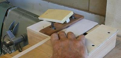
-
Using a drill press for other operations.
Modeler12 replied to Modeler12's topic in Modeling tools and Workshop Equipment
Thanks Dave for this suggestion. I looked up the sander and thought that for the price I could do something like what Garward suggested. I assume you don't use something like this every day. But then again when I cut a lot of strips on my Shopsmith mini table saw, I will need to run a lot of them through a sander. I had thought of doing that on the same Shopsmith, but now I can see having the drill press all set up for the same production run. -
Using a drill press for other operations.
Modeler12 replied to Modeler12's topic in Modeling tools and Workshop Equipment
This is a great idea. I can see a thickness sander in the making. Although I have used a drum sander in my drill press, I have always held the part in my hand or at least loosely on the table. This fixture would allow me to do things more accurately. -
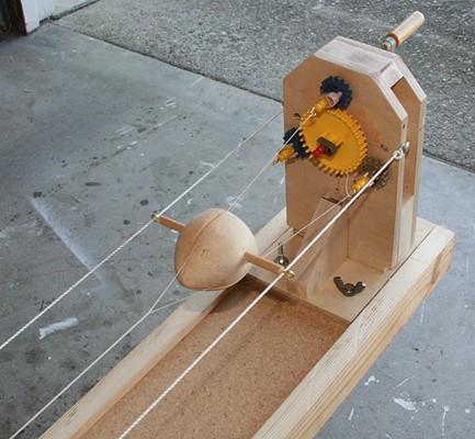
Great idea, Dave. I also found it interesting that you used some gears that appear to be from a KNEX set, right? I used the same gears and other KNEX pieces that I 'borrowed' from one of my grandkids toy box. I used them to make my eight foot long ropewalk. After some experimenting it works great. To speed things up I use an electric hand drill clamped to the end shaft. I might add that the other end can move inside the track but has weights hanging from a pulley to keep the main thread tight. I think I can easily do the serving using this set up. Thanks for your idea. To see more of how my ropewalk works and some examples go to http://www.brentjes.com/ropewalk.html

-
What is your favorite hand tool(s)??
Modeler12 replied to Modeler12's topic in Modeling tools and Workshop Equipment
Ron, I wouldn't be too afraid to try sharpening chisels. If you want to learn more do a web search, but I would recommend that you buy a cheap one (even Lee Valley has some for around ten dollars) and practice a bit. You will find that getting yours back to SHARP is not hard. I have sharpened mine several times and, with a bit of judgement of the angles involved, I have never needed one of those gismos. -
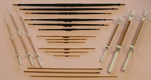
One more set of pictures and then I am where I left off a couple weeks ago. What I have not covered are the rope-walk I made for the rigging lines, a fixture to make rope coils, nor a lot of other details that are covered on my web site. I have made the masts and spars using an old Shopsmith. The picture below shows how I adapted a ‘follower’ to support the center and an end plate for the thin dowels. The dowels were too flexible so I did not use gouges to form the tapers. A lot of filing took care of that. This was before I got a mini lathe for Christmas. I made six sails for the Conny. They include the spanker, three top sails and two jibs. Since the spanker is easy to install before the shrouds and stays are in place, I went ahead with the rigging. Right now the mizzen mast is glued in place and next comes the lower section of the main. Obviously I will have to add the shrouds before the upper parts of the masts are installed. Strangely enough I still have not made the bowsprit nor the rail netting. I will have to buckle down and get going again. But first I need to learn how to use this new format!!!!
- 732 replies
-
- 1
-

-
- constitution
- model shipways
- (and 1 more)
-
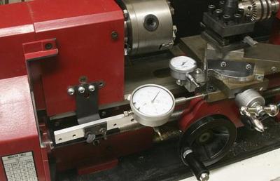
I might add that these mini lathes are really a neat addition to my shop. I bought one on Graig's List for $400 and it included just about all the usual extras such as four jaw chuck, face plate, follower rest, steady rest, extra bits, etc. I have also made some modifications such as a cam operated tail stock clamp and the dial indicators shown below. By the way, the small dial cannot move crosswise and is no danger of being hit by the chuck (of course, large parts could damage both, but they are very easy to remove). In order to install the large one, I had to move the controls to the back. In the US there are at least four companies that sell their own version, but they are all made in China by essentially the same company. Here they include Harbor Freight, Grissly. Little Machine Shop, and Micro Mark.
-
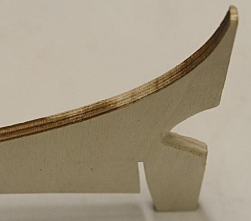
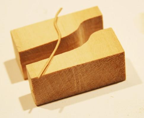
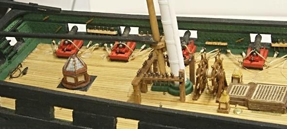
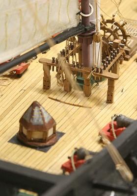
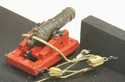
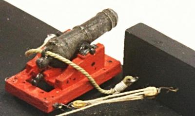
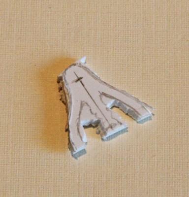
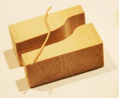
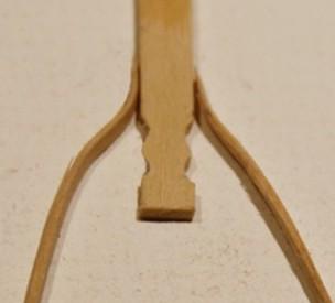
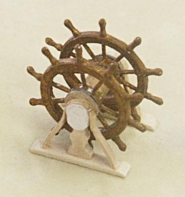
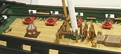
Let me move on to some of the deck furnishings. I will only cover a couple that I think might be of interest. Again the processes were a deviation from the cookbook. Before I do that, let me mention something that I found useful. It has to do with the order of installing exterior parts to the hull. There are several pieces that are quite delicate and when working on the deck parts such as the cannons, it is very easy to damage other parts. In particular I am referring to the cannon lids on the lower deck, the chain plates with deadeyes, and the netting on top of the rails. I went ahead with the cannon lids and ended up damaging some of the wire ‘pull ropes’. I did pre-fabricate the chain plates but held off installing them until I was finished with the deck. Likewise I have not yet installed the netting; even though I have already started with the masts, stays and sails. I had made the twenty cannons using the blocks that were supplied with the kit for the tackles. I was not at all satisfied with the looks of the poor blocks. They were out of shape and way too big. So I ordered some good ones (2.5 mm) from a fellow in Utah. The difference is shown below. The second has to do with making the support frames for the two steering wheels. The cookbook suggested making the two frames by cutting them out of a sheet of styrene. I quickly gave on that and decided to make them look more like the real thing. I formed the four legs as shown below and glued them to the center post. The two blocks were pressed after soaking the piece in warm water.
- 732 replies
-
- 1
-
-
- constitution
- model shipways
- (and 1 more)
-
What is your favorite hand tool(s)??
Modeler12 replied to Modeler12's topic in Modeling tools and Workshop Equipment
This was brought up once before and the consensus was to re-sharpen the blades rather than replacing them with new ones. I find it very quick and easy to use a diamond coated honing tool to touch up a blade that becomes dull. In addition I have a honing rod to further touch up the sharp edges. -
Very impressive work Garward. Making your own cutting bits looks like a dedicated job. I made my square parts of the masts by laminating four flat pieces to the round stock (after filing some flats). That, of course, means that the seams show on two sides, but in my case the masts are painted white, so it did not matter. I did the same thing with the octagonal parts.
-
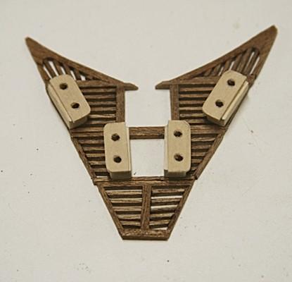
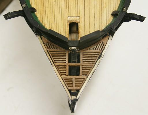
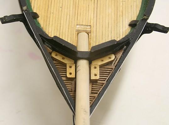
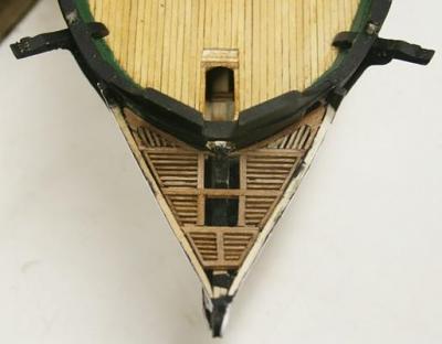
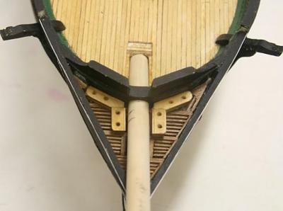
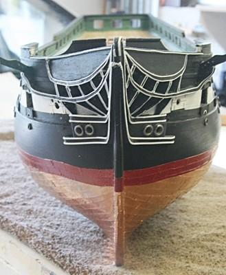
Those of us who have built the bow section of the Conny know that this is one of most difficult part to do right. Each piece is a three dimensional puzzle. I had to completely redo the part that goes from the bow to underneath the cathead. The frontal picture above tries to show this. I also took a different approach with the floor of the head. The kit comes with laser cut pieces similar to the hatch covers, but I had seen drawings that showed slats and a different arrangement of the head seat. I decided to do this in mahogany. It turned out the floor slopes upwards towards the bow and the front seats were at a terrible angle. No way could anyone sit there and do their job. So it was back to the arrangement shown below. It was an interesting diversion and a bit of scratch building.

- 732 replies
-
- 2
-
-
- constitution
- model shipways
- (and 1 more)
-
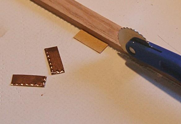
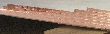
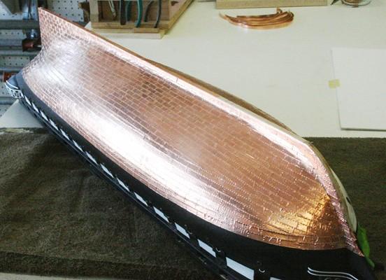
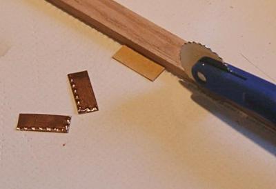
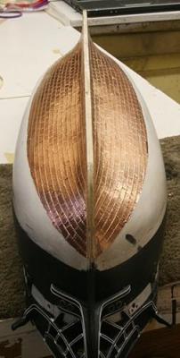
Thanks Steve. Here is more. After the hull was planked and painted I had to add the copper plates. I started by cutting each plate from the roll of copper foil that comes with the kit, but quickly got tires of doing thousands of those one by one. Along comes my wife, watches me and then asks ‘Why don’t you cut longer strips. It would be a lot faster!!!!’ Thanks for wives who are interested. I cut strips about 7 inches long, used a seamstress dimpling tool to simulate the bolts and proceeded with the copper plating. This not only saved me a lot of time, but the alignment of the plates was a lot better. I did use individual pieces near the stern and bow where there are sharp curves.


- 732 replies
-
- 3
-
-
- constitution
- model shipways
- (and 1 more)
-
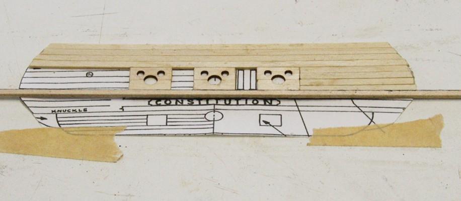
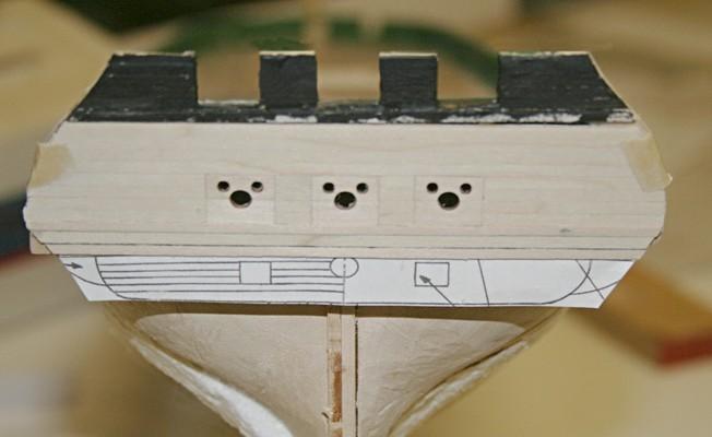
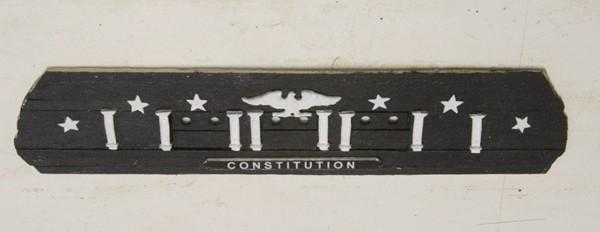
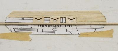
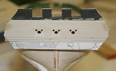
Another example of doing things a bit different was the transom. The cookbook said to install the planks one by one. I decided to make a copy of the drawing (which are close to the correct scale) and glue the planks and gun hatches to that. I was then able to trim and mount this pre-assembly to the hull. One reason for doing it this way was that I wanted to make sure the planks would match those coming from the sides. I wanted the white trim pieces to lign up correctly. I might add that the name Constitution was made by printing a black background on paper and then adding on top of that the letters in white. I had to juggle the font and size to match the name plate, but it came out ok.

- 732 replies
-
- 1
-
-
- constitution
- model shipways
- (and 1 more)