


ikkypaul
-
Posts
83 -
Joined
-
Last visited
Content Type
Profiles
Forums
Gallery
Events
Posts posted by ikkypaul
-
-
-
What lovely work Lawrence. What will be next? Welcome!
- mtaylor, geoff and CaptainSteve
-
 3
3
-
-
-
-
-
-
Hello Edd, a very warm welcome to MSW. What a lovely model - and how complex! All the very best - if you take a look at my restoration project (Blog) on a 3 master square rigged ocean carrier you may get some encouragement from seeing my starting point which was a right old bird's nest of 100 year old rigging. I am 79 and expect to sail this ship later this year!
I look forward to seeing your progress on a blog here I hope.
Paul
-
-
Deperdussin 1911 - thankyou for your comment, much appreciated. Paul
- Keith Black, Tigersteve, mtaylor and 1 other
-
4
-
Thistle17 - thank you. looking at some of others blogsI realise that our community of modellers has some very fine craftsmen turning out superb finished models. They inspire me to keep going. My uncle was only 11 when he finished my model in 1899 - and as i keep going I feel as though I am experiencing some of his challenges. He did it with his bare hands and a few hand tools. I have the benefit of electriciity, light and some modern tools! I am often in awe of that young boy.
I really appreciate your comments, thanks again. Paul
- mtaylor, Keith Black, thibaultron and 2 others
-
5
-
Build Log
Posting #5
Looking back on the previous instalments I feel I glossed over the many and varied
tasks, some very small yet necessary, involved in advancing the project. These are not necessarily in chronological order.
- shaping wood for replacement bulwarks and fitting them to the hull;
- preparing hull for painting, and painting it;
- making new main pin rails, including marking and drilling the pin holes;
- repairing bitts and fiferails;
- making new belaying pins from copper wire. (Note: copper or brass wire has been used instead of steel as would have been on an actual ship);
- making triple “sheave” blocks needed for upper top, upper topgallant and royal yard halliards;
- fitting halliard tyes;
- rigging halliards for the hoisting yards i.e. upper top, upper topgallant and royal;
- adding fittings (“spider bands”) to each mast;
- attaching chain plates to hull for each mast;
- making and installing main shrouds;
- fitting capstays to each mast;
- installing trestle trees, main and mizzen masts;
- making and installing mizzen shrouds;
- making new tops for each mast
- rigging fore-topmast back-stay;
- fitting ringbolts for anchoring main & mizzen stays;
- rigging mainstay and mizzenstay;
- fitting spreaders for backstays;
- rigging topmast, topgallant and royal stays plus the associated backstays;
- rigging ratlines on each of the 9 sets of shrouds;
- incidental painting of mast sections, tops and trestle trees;
- refurbishing existing running rigging blocks, and making some new ones;
- making and fitting sheer poles;
- resetting of shrouds;
- refitting bowsprit guys;
- refurbishing existing yards, and making necessary replacements;
- preparing each yard by fitting the necessary fittings (e.g. jackstays, eye bolts,
foot-ropes, rigging blocks) for the running rigging;
- fitting yard lifts;
- fitting buntline and clew line blocks on all 18 yards (small beads);
- preparing and fitting wire brace pendants for each yard;
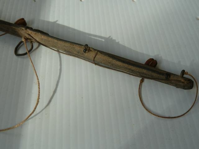
- making a pair of bumkins that take rigging for the mainmast braces;
- fitting braces, all of which involve purchases;
- refurbishing and fitting the deckhouse;
- repairing and fitting the skylight over the main cabin;
- calculating dimensions of the spanker gaff and boom.
And as you seasoned modellers well know the task list keeps on growing. Pictures below are just a few from 2013 (4 years ago) to show a little of the progress.
1. My improvised bumkin to accommodate the main lower braces.
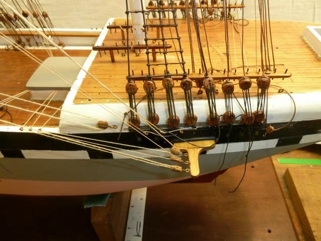
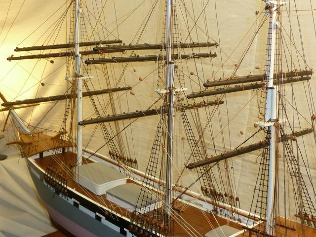
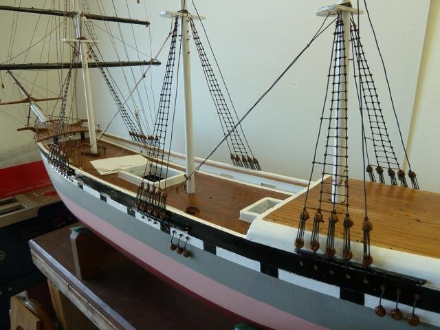
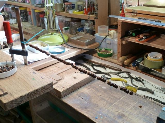
2. A more general view of the standing rigging – halliards for the 3 hoisting yards, lifts for the yards and braces for the yards.
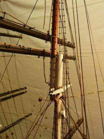
3. Some detail of the mainmast trestle trees.
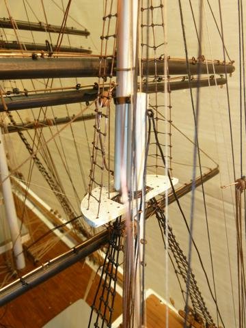
4. Detail of mizzen top.
- aaronc, Tigersteve, Jack12477 and 10 others
-
13
-
-
Build Log
Posting #4
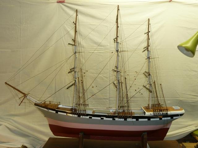
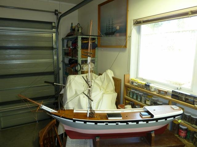
Stepping of Masts and Rigging Shrouds
With the foremast having already been stepped the original shrouds were stripped off, and the original channels refurbished and fitted. The original main and mizzen masts were stepped and a complete new set of shrouds were rigged. The shrouds are copper wire, as are all the mast stays that came a little later.
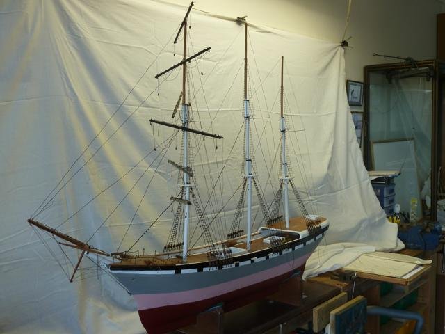
Next came the “tops” for each mast all newly fashioned from rimu and shaped and drilled as per the originals which had suffered over the years. New topmasts and topgallant masts were made of New Zealand kauri a very straight-grained timber that was extensively used for masts and spars on the windjammers in the 1800s and 1900s. The fids are short bits of copper wire – the originals. These mast sections were swayed up, as they say, and shrouds rigged for topmasts and topgallant masts. Wire for these is smaller in diameter to keep a semblanceof scale. Ratlines were all done using rigging thread.
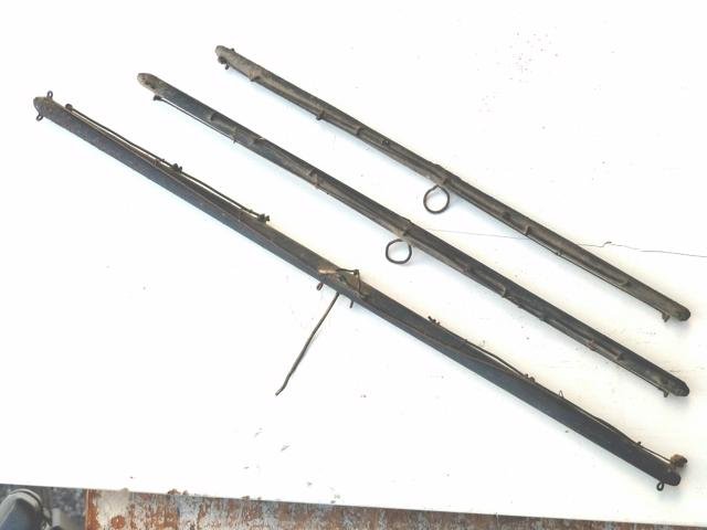
Then came the fore and backstays. Following on came the job of refurbishing the sound yards and making up just a few to replace those infested with woodworm. You very quickly learn that spars have a great many holes needed for the various fittings. The little drill press again was invaluable. Julius has simply made up copper wire eyebolts which he stuck into the holes where needed and for opposing fittings used a single piece of wire with an eye on each end. The photos indicate the “before” state, as well as the typical home-made fittings.
Thus, having now fitted the standing rigging, and the preparation of the yards, it was time to sling the yards into place along with their associated lifts and halliards. It was quite an eye opener to learn how much cordage was needed to reeve the halliards in their triple block configuration.
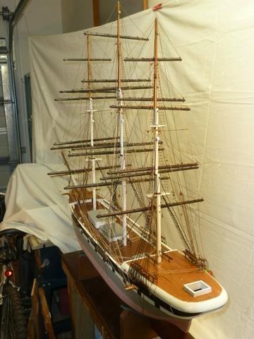
As can be seen in 2 photos above, the transformation to having the running rigging for the yards - the braces - in place is significant. I can tell you that quite a few hours was taken up in achieving this milestone. To this point in the project, I still had enough of the original rigging blocks for this phase of rigging. My apologies for the imperfect lighting for the photos. Please ask if you would like further detail on any aspect of the project.
- Tigersteve, Story, jud and 13 others
-
16
-
-
Build Log
Posting #3
Preparations for Standing Rigging.
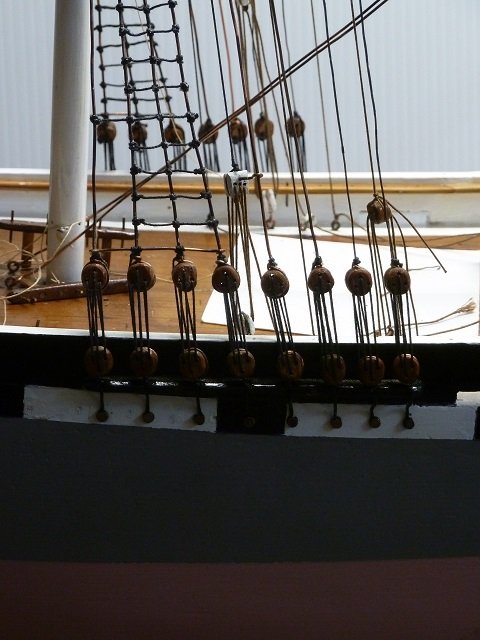
As already mentioned 96 deadeyes (blocks) were needed in order to set up shrouds and backstays. The photos below show the development. From strips of hardwood the basic shape of the deadeyes was formed; then grooves were cut using a parting disc on the (Dremel) drill press – this was the starting point for the circumferential grooves that were completed later.
After scribing the lines for the various holes in the blocks the drill press was used to drill all the holes. You sharp-eyed folk will notice the “fairing” of each hole – my method for doing that was simply to run some nylon monofilament (fishing line) backwards and forwards through each hole to produce the fairing in the correct direction.
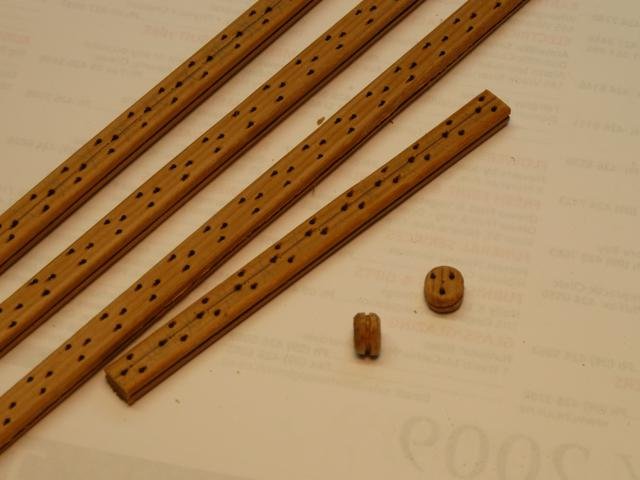
Having then cut the strips into blocks it was a matter of using very small files (pattern files?) to cut the circumferential grooves.
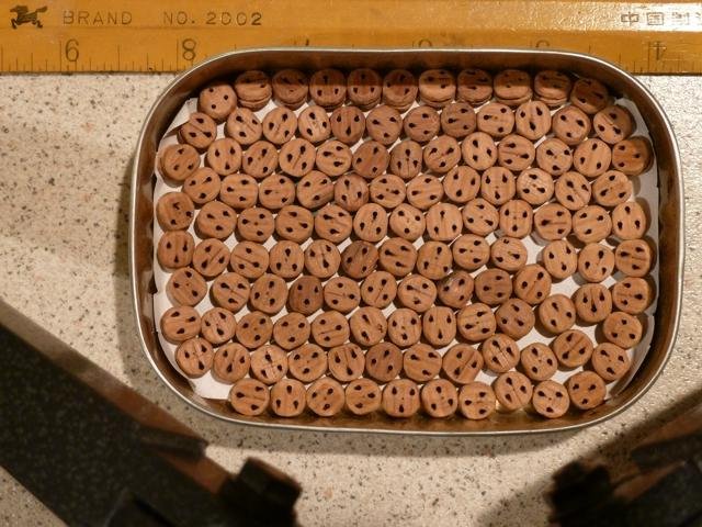
Next was coating them with polyurethane as you can see below.
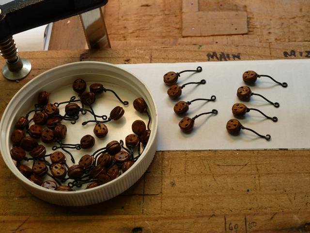
Finally the “chain plates”, made from wire, as Julius had done originally, were fitted to the blocks as shown. As many scratch modellers find, you are often making up a new jig for making parts, such as chain plates. I have now quite a collection of such jigs
Reflection. Some of you probably wonder why I have made the various fittings instead of commercially manufactured fittings obtained from model makers’ stores. My main purpose in attacking this project is to turn this model into a memorial for my uncle. So I felt it worthwhile to set to and do it as much as possible by hand. I wanted to experience something of his life and the challenges he probably met in the building process. I learned very early in this project is the requirement to be patient! If you do something in a hurry you can quickly end up damaging your earlier work, so patience becomes progressively more important as the model becomes more complex, especially in the rigging.
Note: This is a retrospective build log, the project having seriously recommenced in 2010. In 1968 I had replaced: some of the bulwarks, the broken bowsprit, the deck over the focs’le, the foremast, fore topmast and foretopgallant mast, the mizzen mast, then set up foremast shrouds and stays, and had rigged the halliards for the foremast yards. Then a glass case was made which has helped keep the model free from dust.
Please therefore understand that I write now with the benefit of some hindsight!
Now to the business of stepping some masts.
- Oystein, Tigersteve, gieb8688 and 13 others
-
16
-
Build Log
Posting #2
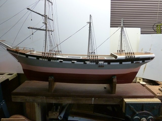
The model: representing a 3 Mast full-rigged ship - square sails on each mast.
Note: scale and all dimensions are estimated
Scale: 1:55
Full size hull length: 55m (190 feet)
Beam: 10.8m (35ft) Mainmast truck to deck: 43m (141ft)
Truck to waterline: 46.75m (153ft)
Truck to Keel 50.6m (167ft)
Main course yard: 21m (68ft)
Sail area: 1,800 sq.m (19,500sq.ft.)
Displacement: 760 tonnes (750 tons)
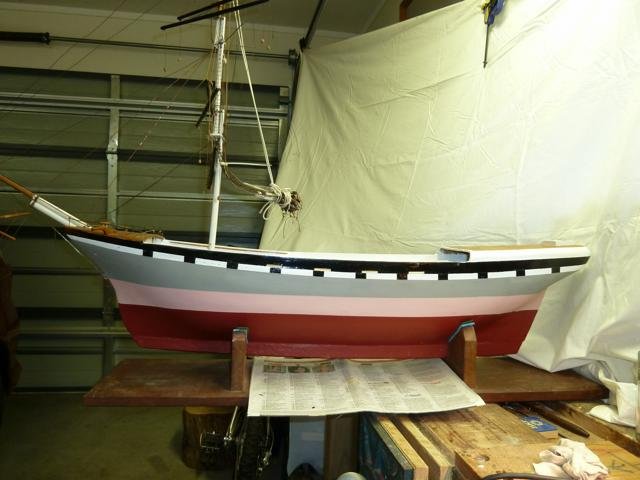
In the photo below the first thing to note is that the hull is fashioned from a single piece of wood. Reburbishing it involved cutting out most of the original bulwarks, which being made of quite soft wood – probably our native (NZ) white pine – which woodworm (borer) loves! Replacements were made using our NZ Rimu (red pine which was NZ’s main building timber in days gone by) by copying the originals. Of course new pin rails were needed too and rimu was my choice for these. The original belaying pins were simply made from copper wire of the diameter that fitted cosily into the holes.
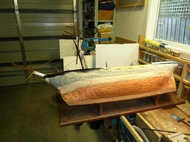
In this careening position can be seen the remains of the original livery colours. The light grey above the waterline has given the only clue I have as to perhaps the inspiration for this model. Only recently – early 2017 - an acquaintance on seeing my model, exclaimed that the livery was that of the “J.J. Craig Line” of Auckland which operated in the first decade of the 20th Century. So it seems a little more than a possibility that a ship of this line may inspired that young lad, my uncle Julius. Note the keel running the full bilge length – it is solid lead.
Photos below shows readiness for stepping main and mizzen masts, and for that 96 deadeyes were needed.
-
-
Welcome from me too (in Auckland NZ). As a relative new boy in MSW I am impressed with the diversity of activities by people of all levels of craft & knowledge skills. Me? Well I am restoring a square rigger built over 100 yrs ago by a boy of 11 years old. DO enjoy being with MSW.
Paul
- geoff, FrozenRabbit471, mtaylor and 1 other
-
4
-
Thank you Tigersteve. Paul
- mtaylor, thibaultron and Keith Black
-
3
-
DocBlake - Hello, thank you - yes this is a retrospective build log as I've only recently joined Model Ship World; my model is - apart from sails - virtually completed. I've lots of photos so you'll see the development over the near future. Paul
- thibaultron, druxey, Keith Black and 1 other
-
4
-
rwiederrich - Hello, thank you - yes I have reused as much as I can and have hand made all other new parts. Paul
- Keith Black, mtaylor and thibaultron
-
3
-
druxey - thanks for your encouragement - it is quite an adventure isn't it?
- mtaylor, thibaultron, druxey and 1 other
-
4
-
Jim Lad - thank you - upwards of 1500 hours spent to date. You're right - a big job.
- druxey, Keith Black, thibaultron and 1 other
-
4
Hello all from Staffordshire England
in New member Introductions
Posted
Welcome to MSW Smudger. One of the nice things about MSW is that you can feel at home whether like me you are new to the activity or whether you are long experienced. I'm from down under (NZ) and being very much a maritime nation there are a lot of folk interested in ships and boats of all kinds. Go well!
Paul