tlevine
-
Posts
2,033 -
Joined
-
Last visited
Content Type
Profiles
Forums
Gallery
Events
Everything posted by tlevine
-

Problems with blackening brass
tlevine replied to Desertanimal's topic in Metal Work, Soldering and Metal Fittings
I have the best luck by soaking the parts in warm Sparex, followed by a dip in water and then in a 1:5 solution of Birchwood Casey to water. I give them several short dips of 15-30 seconds with polishing in between. Finally, they get a thin coat of Dulcote. -
Welcome to MSW! Some people prefer to rig fore to aft. Others, just the opposite. A good rule of thumb for deciding whether a line is found port and starboard vs. one side only is to consider what each line is used for. As far as making masts, take a look at this. Scroll down to installment 20.
- 32 replies
-
- 3
-

-
- Bounty
- Constructo
- (and 1 more)
-
3D Printing Cannons in Resin
tlevine replied to thibaultron's topic in 3D-Printing and Laser-Cutting.
The cannon files are available on the NRG website in the Resources section. https://thenrg.org/page-1075420 Thanks, Ron. -
Do donations to the NRG also support MSW?
tlevine replied to Wawona59's topic in NAUTICAL RESEARCH GUILD - News & Information
Absolutely! And thank you for the donation.- 1 reply
-
- 6
-
-
Working with blackend brass.
tlevine replied to SiriusVoyager's topic in Metal Work, Soldering and Metal Fittings
Liver of sulfur works on copper and silver, not brass. -
Working with blackend brass.
tlevine replied to SiriusVoyager's topic in Metal Work, Soldering and Metal Fittings
If you put an oil based finish on the deadeye before placing it into the chainplate, you can put the deadeye/chain plate assembly into Birchwood Casey without staining the deadeye. -
Although I cut my planks on a table saw, these planks can easily be cut by using a straight edge (aka steel ruler) and an Exacto knife. It isn't critical to have these planks exactly the same width.
- 80 replies
-
- 3
-

-
-
- rigging/masts
- NRG
- (and 2 more)
-
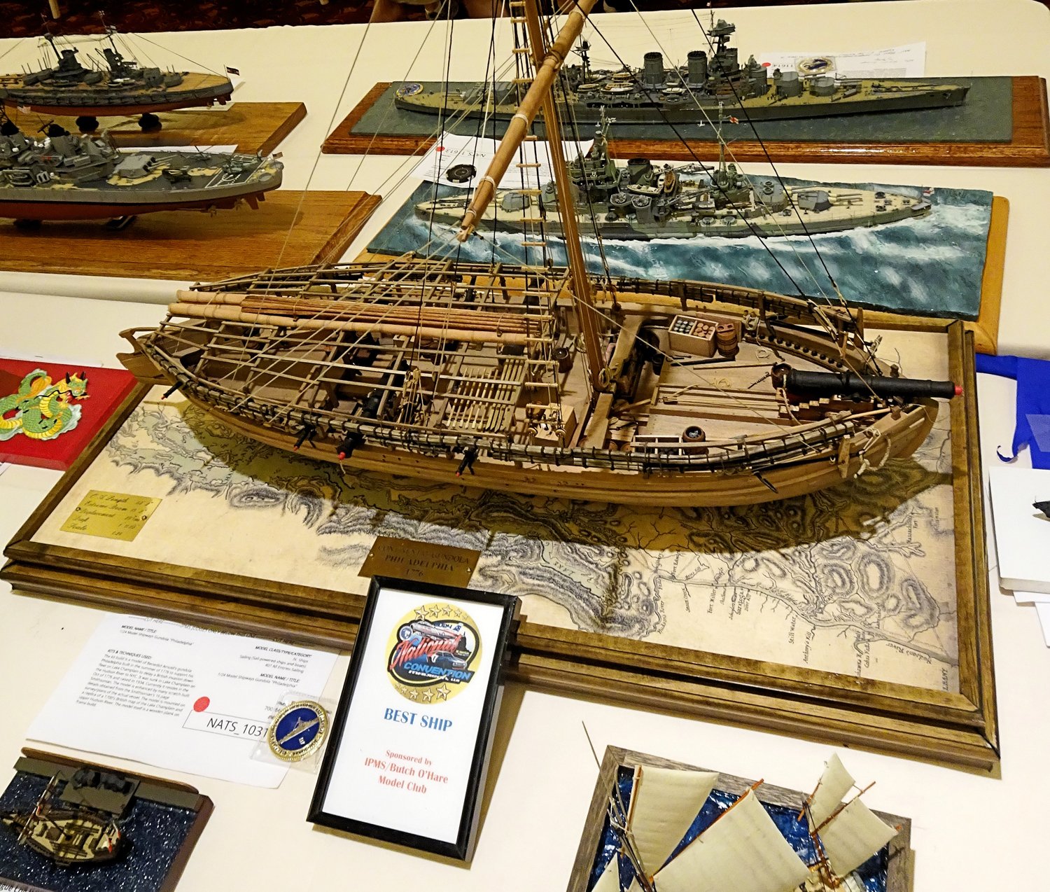
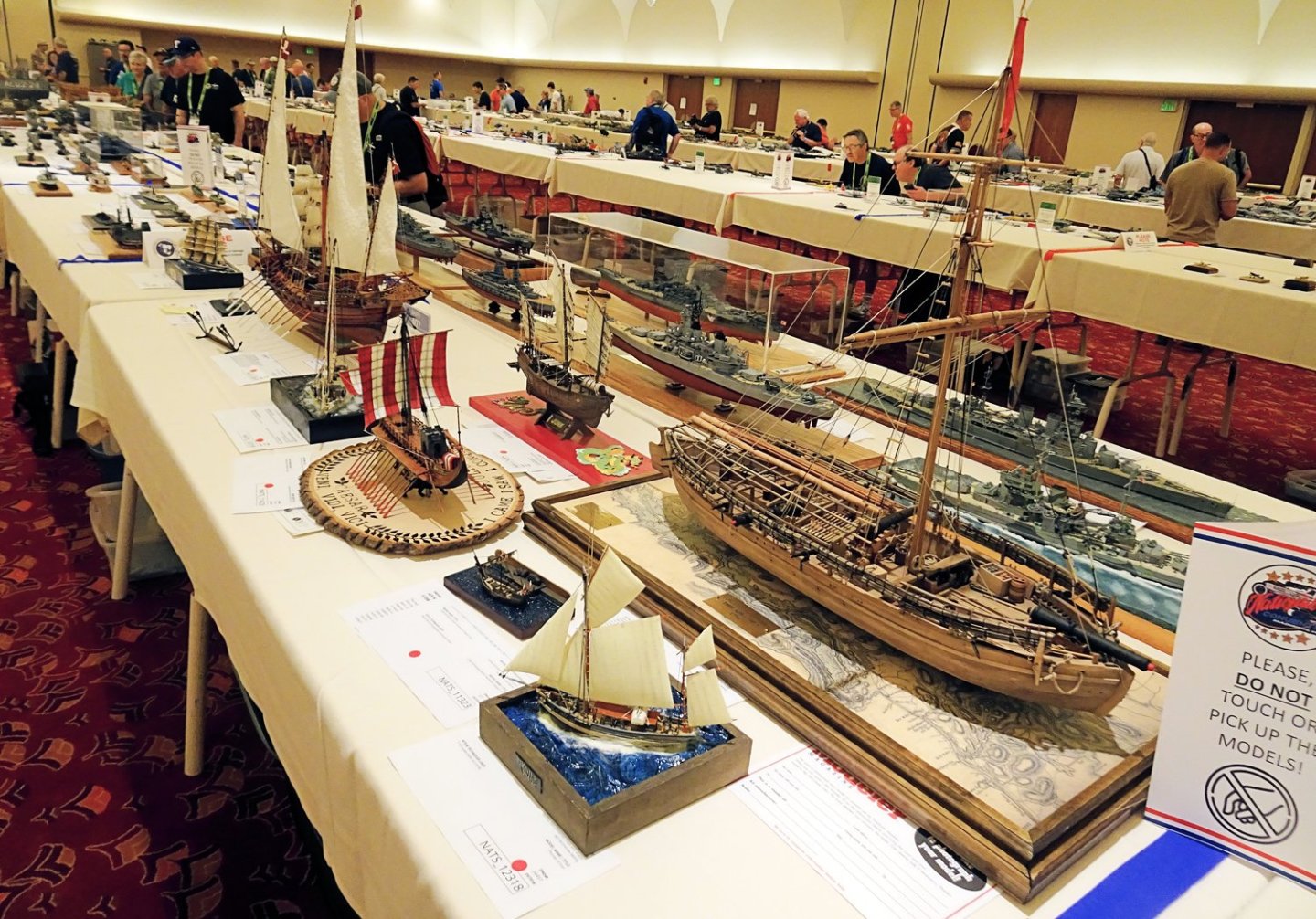
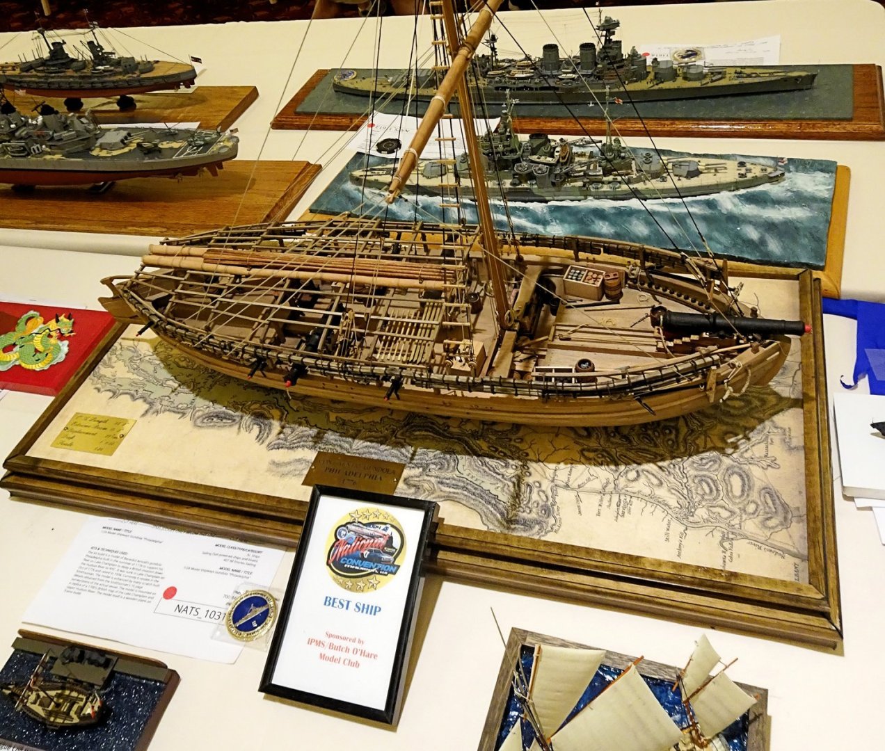
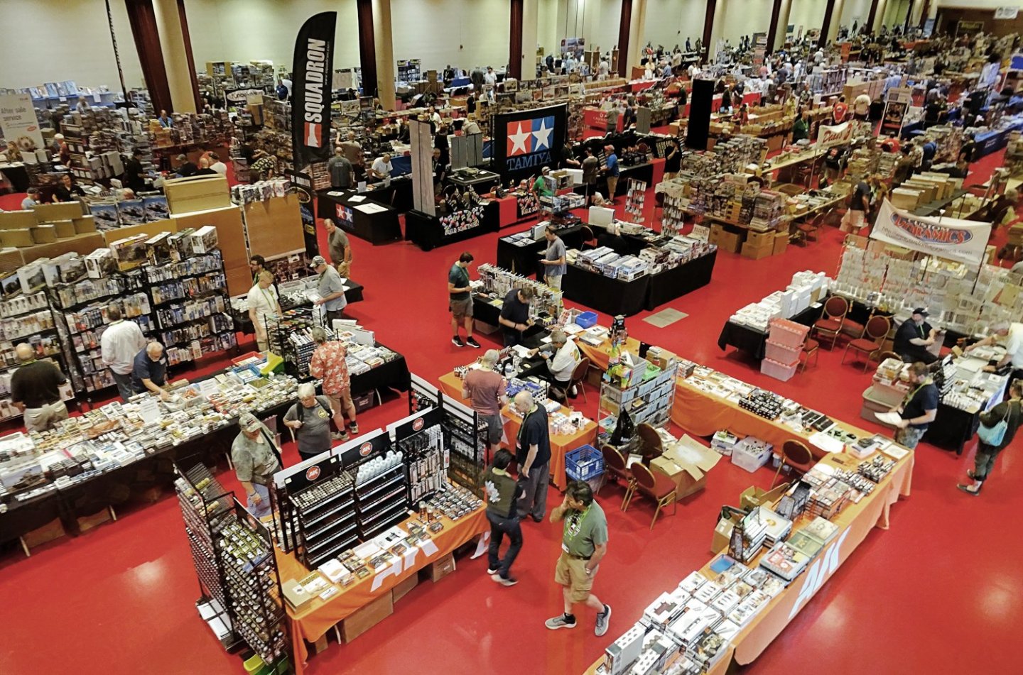
Last week the IPMS had its annual convention and model contest in Madison, WI. The NRG attended the show as a vendor to promote the Guild and several of our members had boats in the competition. NRG Director Sam Parent won Best Ship Model with his model of the Philadelphia. Congratulations, Sam! There were two banquet hall sized rooms filled with models and even more space for the vendors.

-
- 15
-
-
For example "silver soldering", which fuses the metals by heating it almost to its melting point.
-
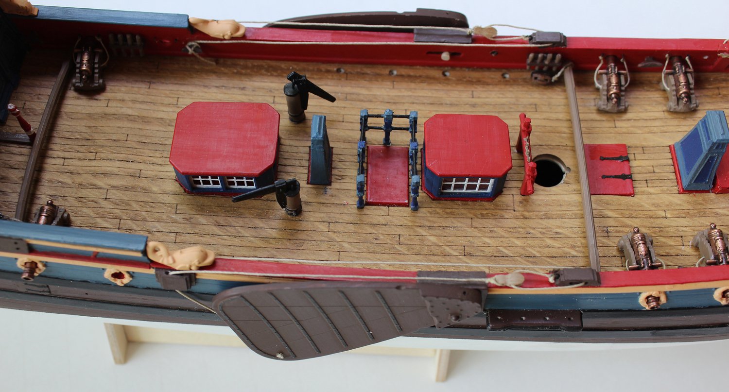
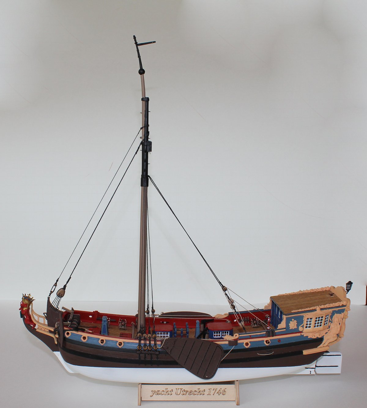
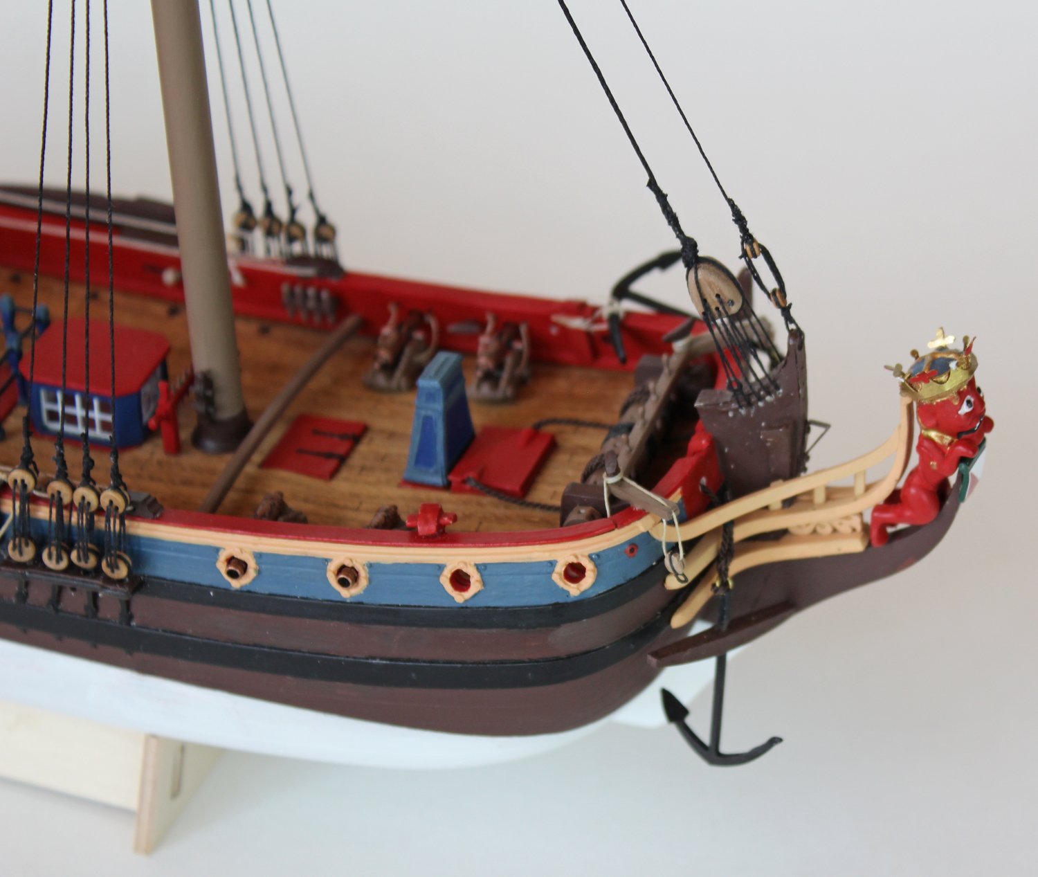
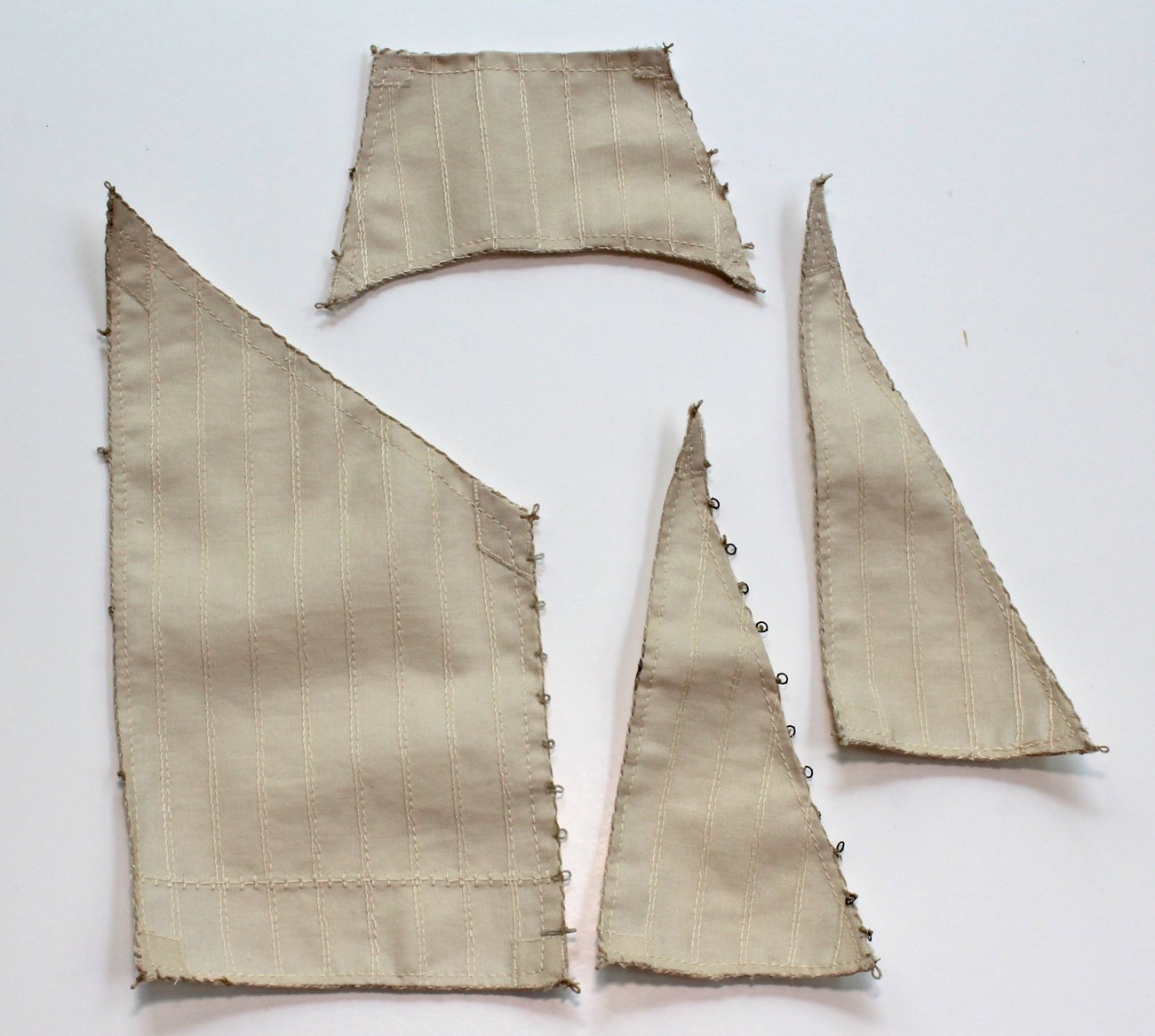
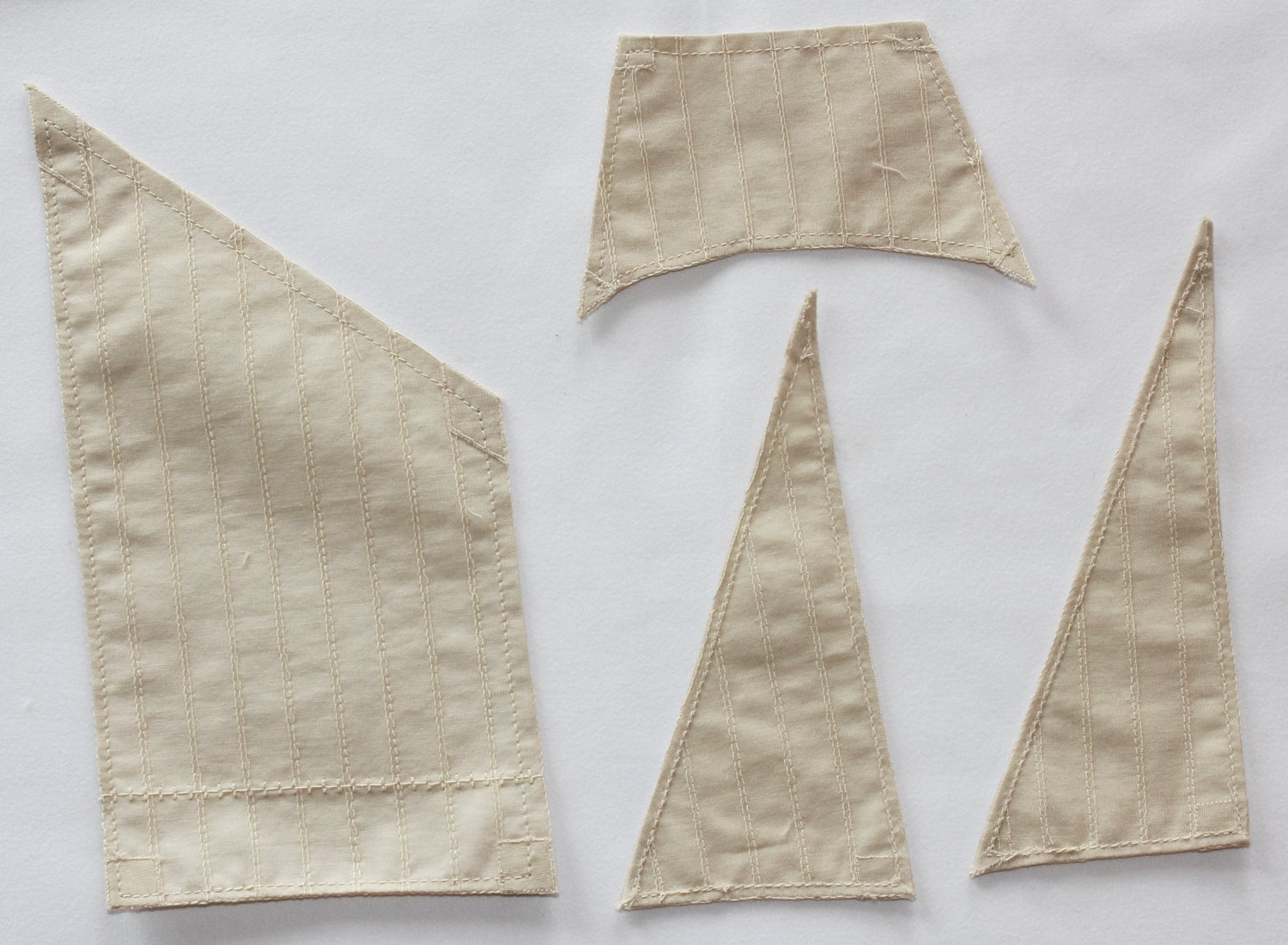
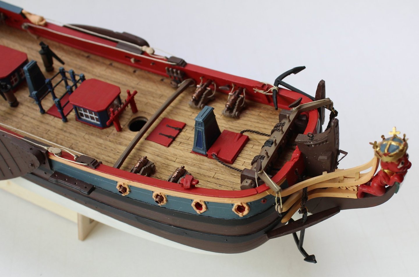
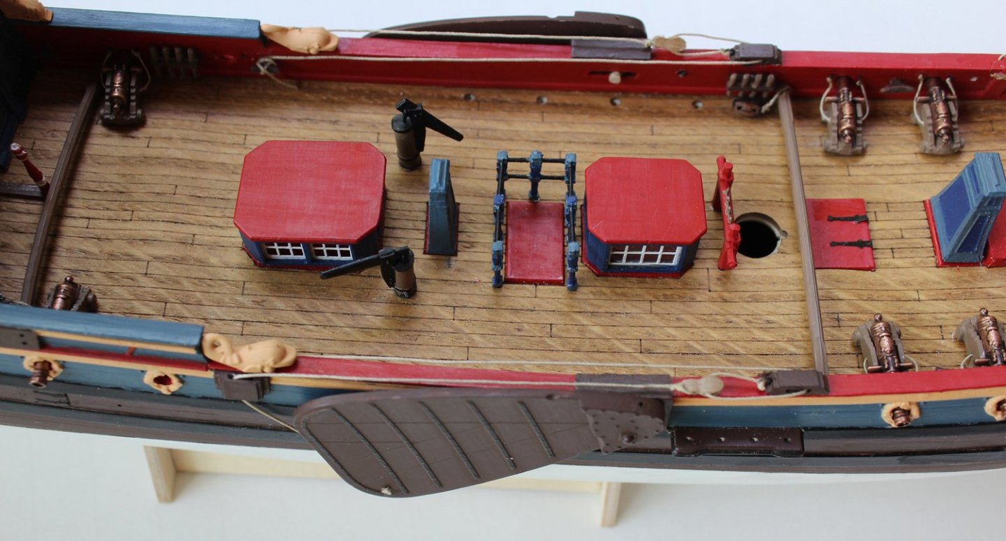
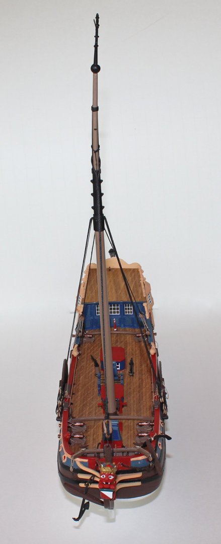
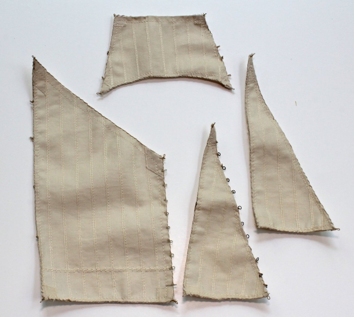
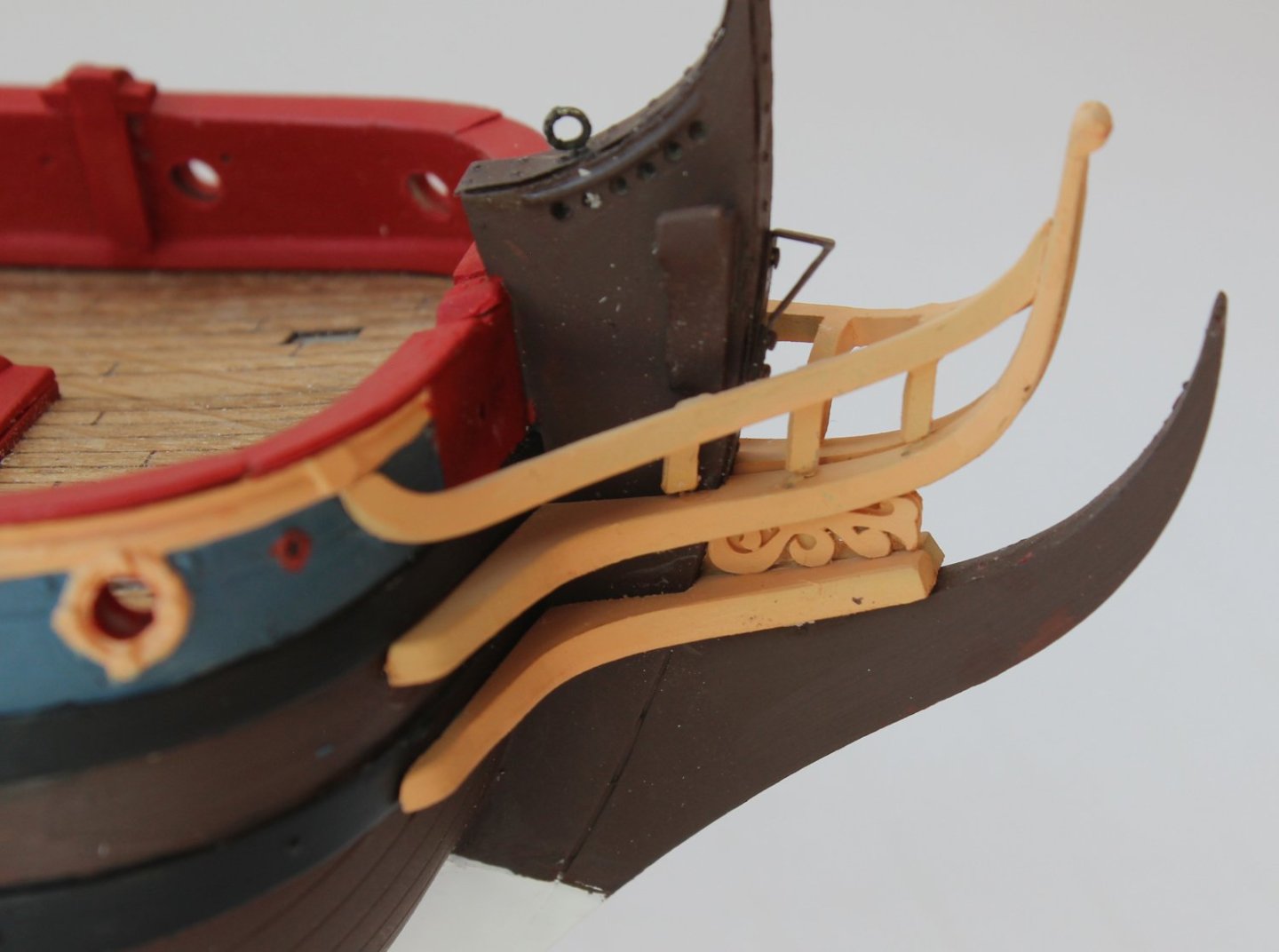
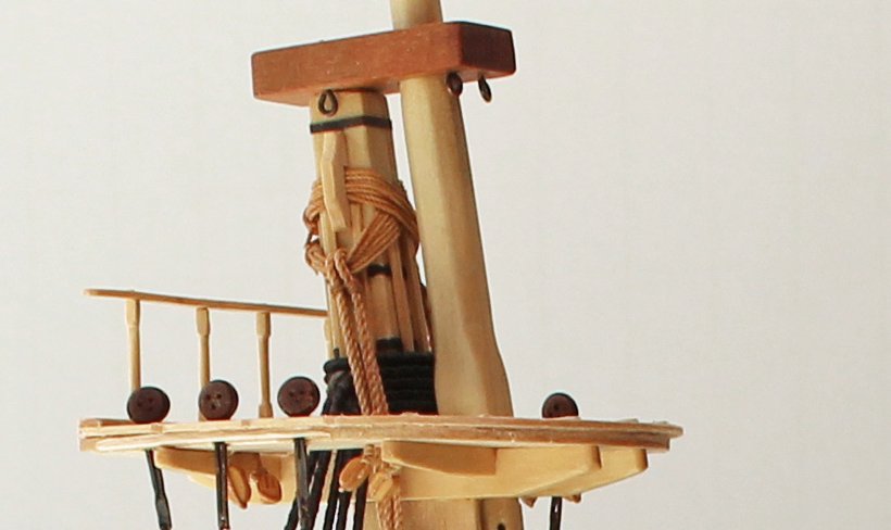
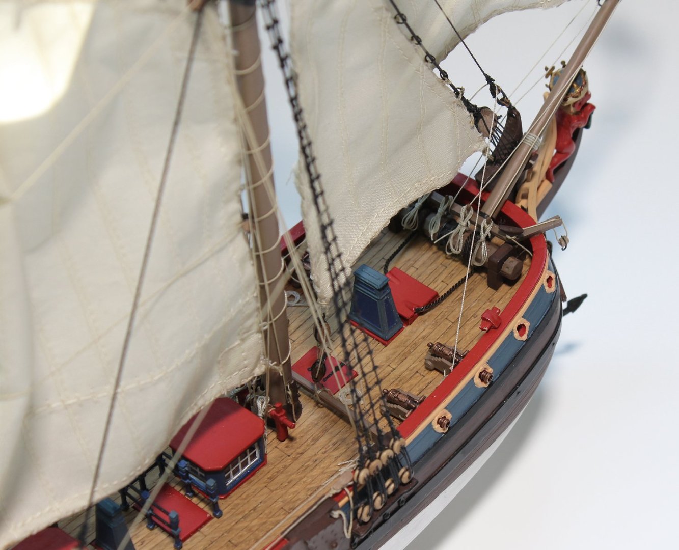
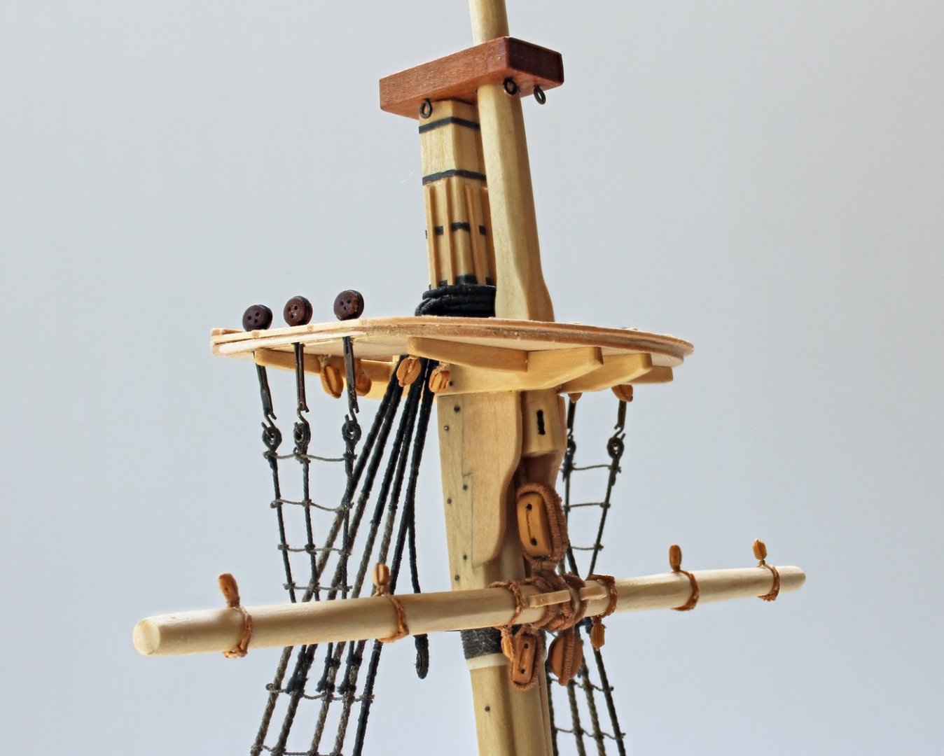
At this point, most of the deck structures were installed, including the pumps, windlass and pin rail that fits over the windlass. The guns were made of bronzed metal, with good detail. The carriages were simplified as was the gun’s rigging. This would be another place where some research and scratch building would take this model to the next level. The pins are nicely shaped and to scale. Again, everything was painted before installation. I could not figure out how to install the leeboards from looking at the pictures in the manual. I looked at Angarfather’s scratch build log of Utrecht and was able to see how it was rigged. The anchors were added next. The hawser cable runs below the windlass and passes to below deck through a hatch behind the windlass. I chose to show one anchor hauled in and the other hanging free. The masting and rigging were next. The two halves of the mast were glued together and weighted down until the glue had cured. However, the two mast halves were warped in the plastic fret and even with weighting the assembly, it was warped. I was able to partially correct this later with the rigging. On this boat, the topmast bends forward and has a sheave running through it. This can be seen in the round black bulge halfway up the topmast. The pictures show the forestay, fore preventer stay, backstays and shrouds installed. The manufacturer chose to show tarred like for the shroud and mainstay lanyards. Again, I went to Hartmut’s build log for direction and he shows untarred line for the lanyards. Additionally, the five hole block for the forestay should have eight holes, with a corresponding number of holes on the stem. The instructions have nicely detailed sketches of the various knots and methods to rig the blocks and deadeyes. In the last two pictures you can see that the port top rail and timbers is missing. This broke off the model and fell into a floor register, never to be seen again! The ratlines were installed next. I used the same number of rows of ratlines shown in the instructions and was very frugal with the amount of line left at both ends. There was not enough line provided to finish the ratlines. I had line that was almost the same size and used that to finish them. Since the model was not going to be moved much more, I installed the rudder. The rigging for the gaff and yards was straight forward. Each block is color coded, making it easy to select the correct block for the line. These are very nicely shaped blocks, including the fiddle blocks used to haul in the gaff. Sorry, but I forgot to take any more pictures until I started to work on the sails. This is the premium version of the model, so it came with pre-sewn sails. The instructions include full-sized templates for making your own sails, along with directions for installing the tabling, bolt ropes and cringles. The fabric of these sails was of good quality but the hem was sewn very poorly, and there was fraying in several areas. As this was an OOTB build, I did not resew them. I would suggest to someone doing this build to not get the premade sails. Make your own from cloth or silkspan and add the details. I added the bolt ropes, cringles and metal rings to the sails. The sail rigging diagram was a bit difficult for me to follow. There were instances where I could not tell whether a particular line was on only one side or both port and starboard. There was one other minor issue; there was insufficient line to finish the model. Specifically, the natural 0.25 line. Again, I had line left over from an old kit which was almost the same diameter and used it as a replacement. My estimate is that 50% more line was needed than provided. I used 24-gauge brass wire inserted into some of the sail hems to give the sails some life. Nothing was applied to the sails to otherwise stiffen them. Finally, the flags were installed. I cut them out and moistened both sides with dilute white glue. While still wet, I shaped them and let them dry overnight. They were hoisted and their shapes were tweaked by moistening them and holding them in position until dry. So here she is finished. As I said at the beginning, this was an as-built kit review. There are a lot of nice things about this kit. Hull, bulkhead and mast detailing is very sharp. The resin decorations, including the figurehead are wonderful and fit perfectly. The blocks are high quality. There is a lot of room for improvement and correcting the inaccuracies. As far as improvement is concerned, better quality control would have seen the miscast head timbers and the warped mast. A modern kit should not require as much filler as this one did to correct gaps in the hull. The photoetch windows were nice but the ringbolts should have been supplied as just that, ring bolts, not flat pieces of brass and white metal. And finally, the inadequate supply of line is inexcusable. If you are a plastics modeler trying to decide whether to start building ships, you are not going to have a stash of line to supplement the kit supplied material. For someone who wants to detail a kit, this is a great option. Even with the problems, she builds up into a pretty model. There are a lot of small things that can be done to make the boat more historically correct. The first two would be to purchase Ab Hoving’s book on the Utrecht and find pictures of the replica on the internet. The pictures will allow you to use the correct paint scheme. Other areas for detailing include hand laying the deck, correcting the inboard leeboard connections, properly rigging the guns, using the correct types of line for the rigging and making your own sails. Thanks for following along for this kit review.


- 14 replies
-
- 11
-
-
-
Well said, Schmidt. Like I said in the beginning, if someone wants to do some research and kit-bashing, this is a very nice kit. When I took it to my local club, a couple of the guys had trouble believing it was plastic.
-
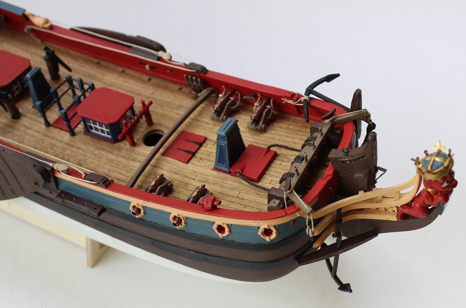
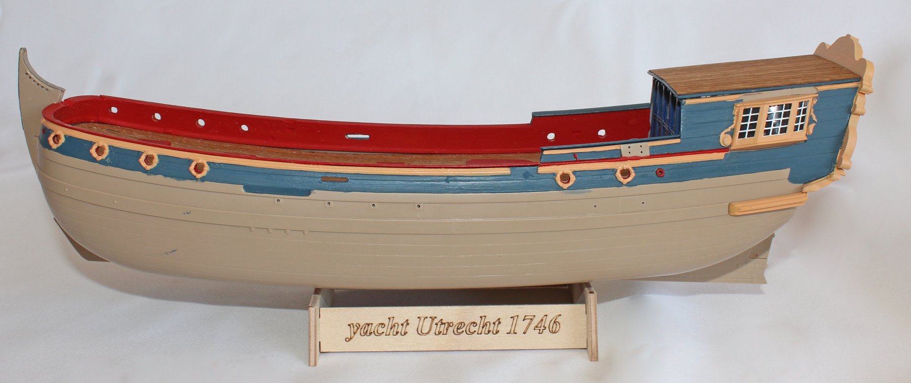
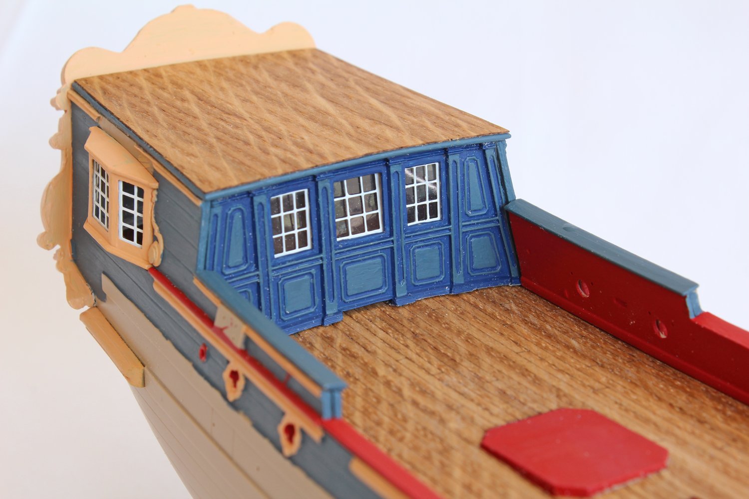
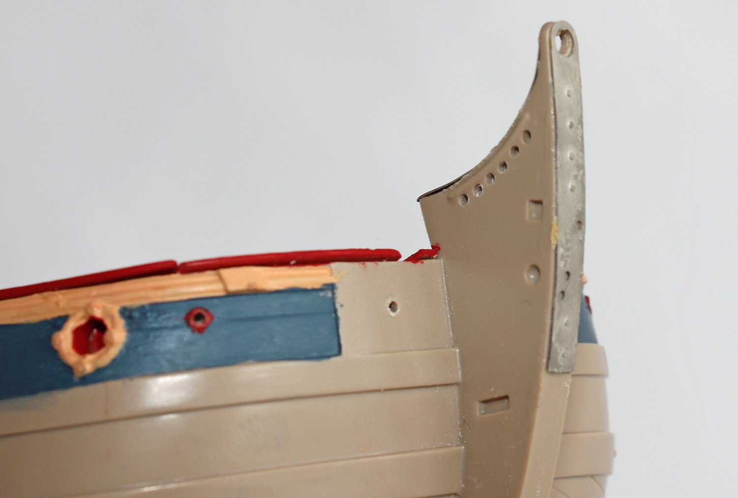
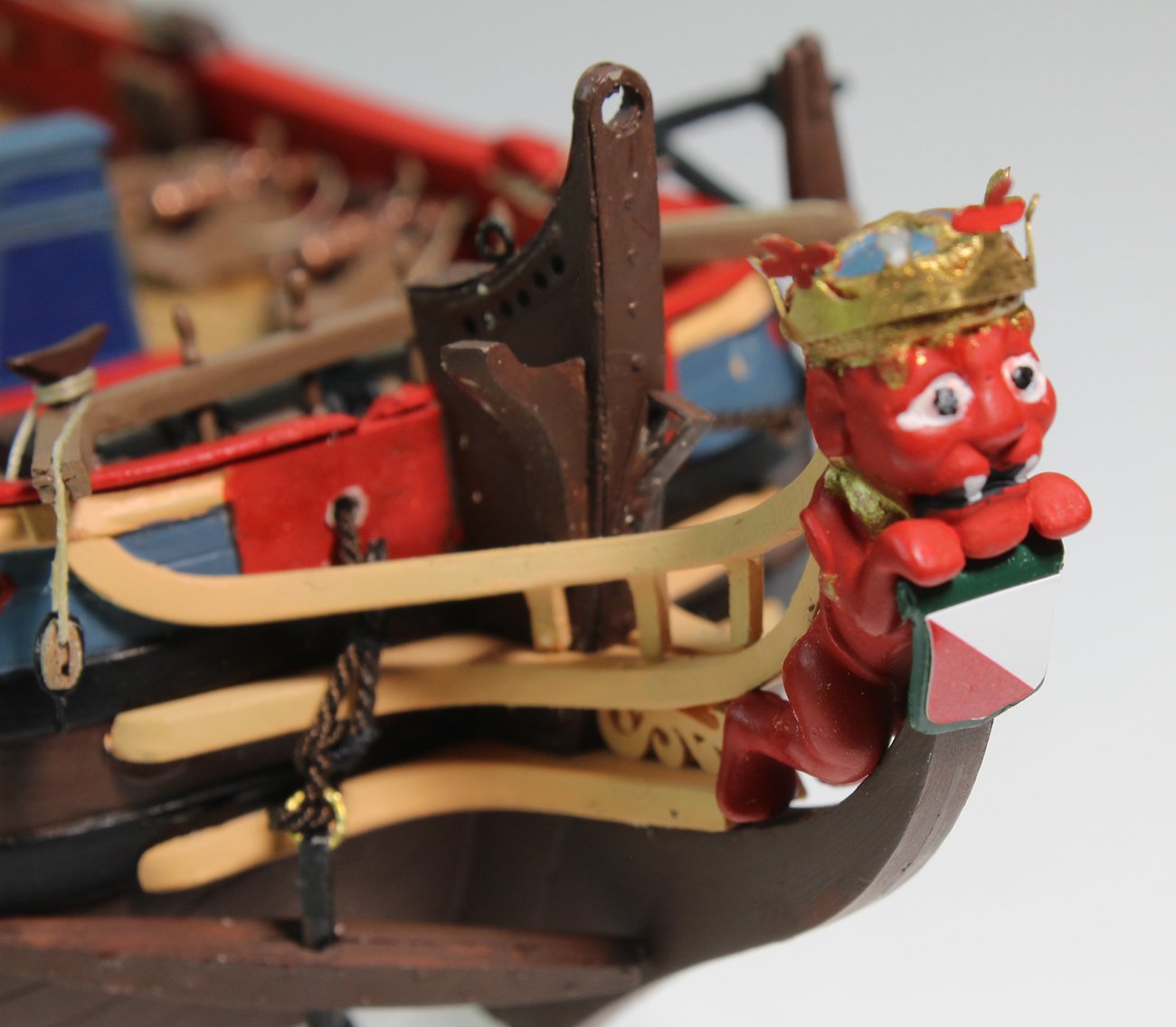
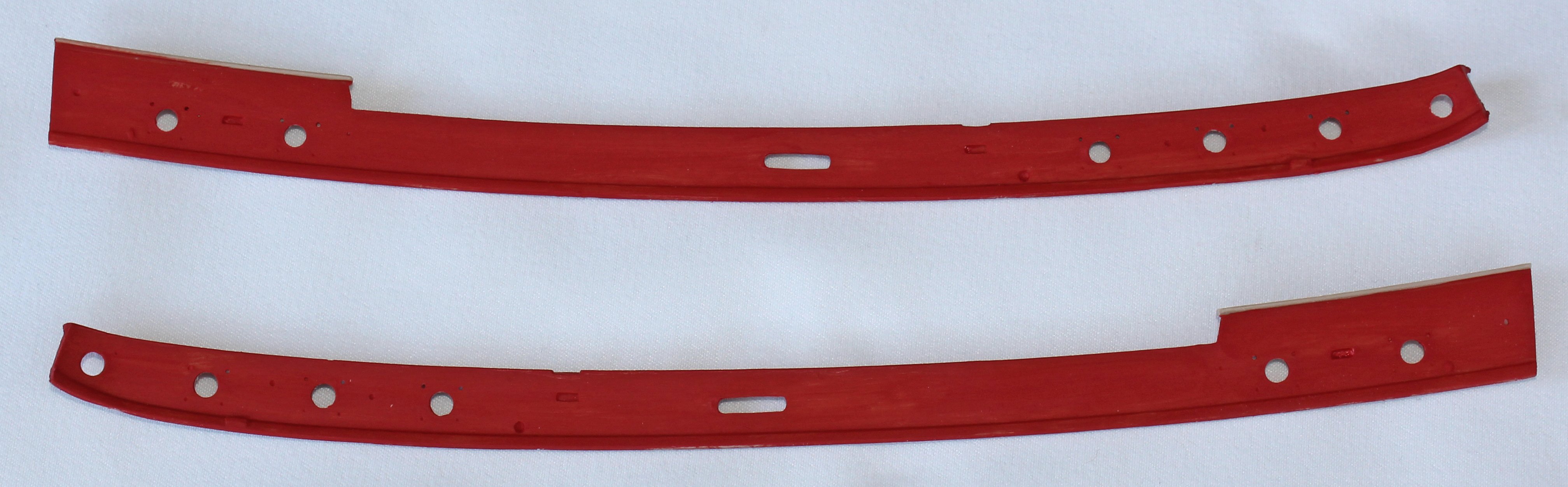
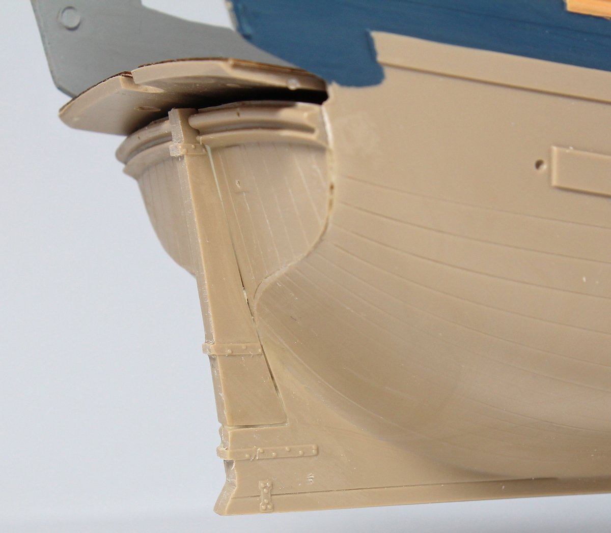
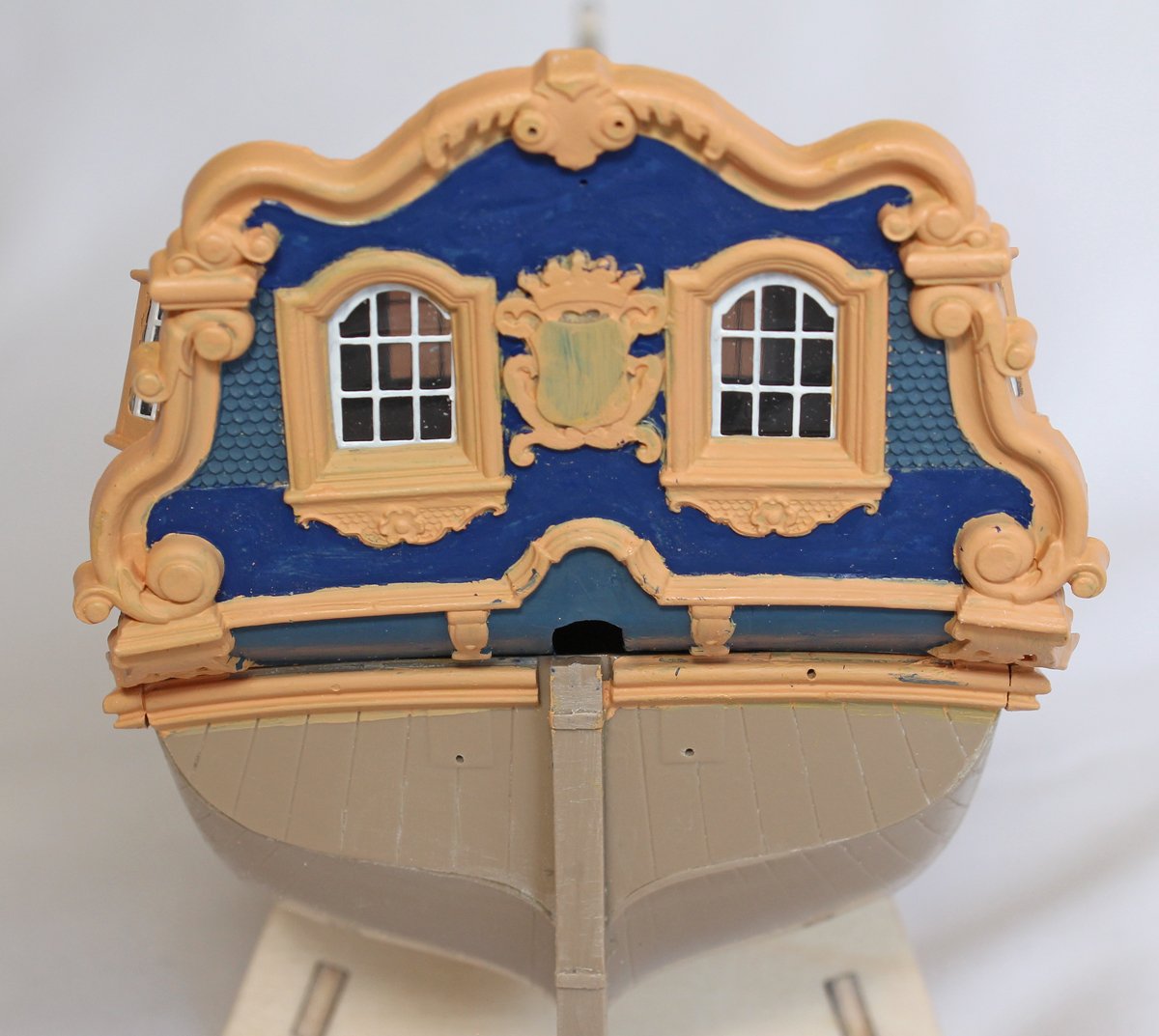
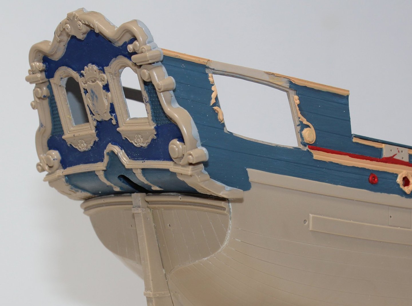
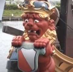
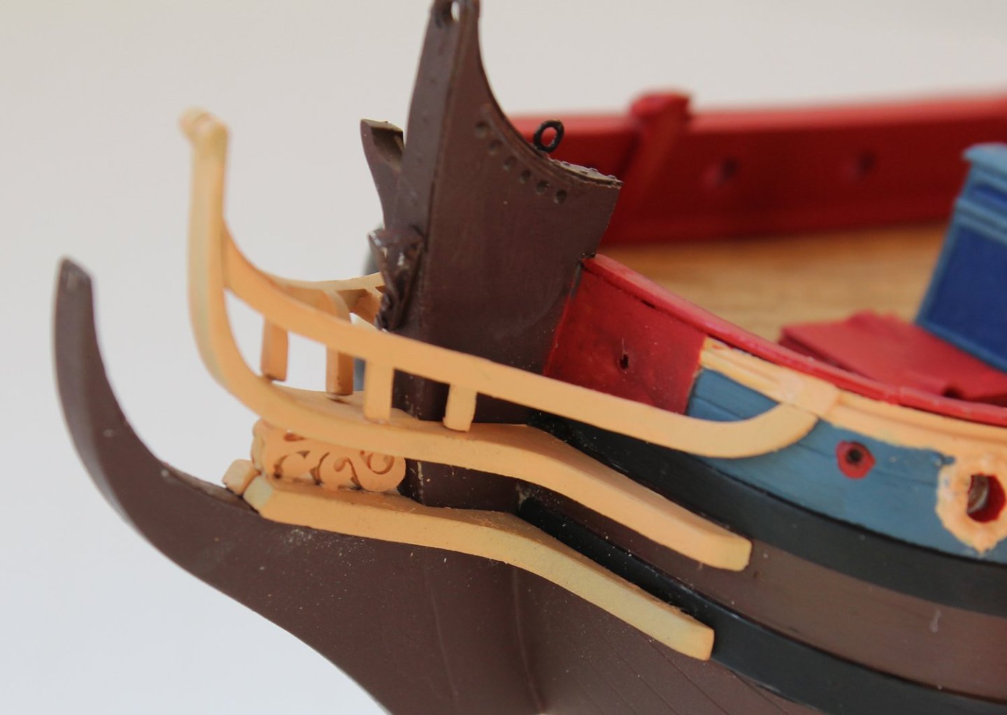
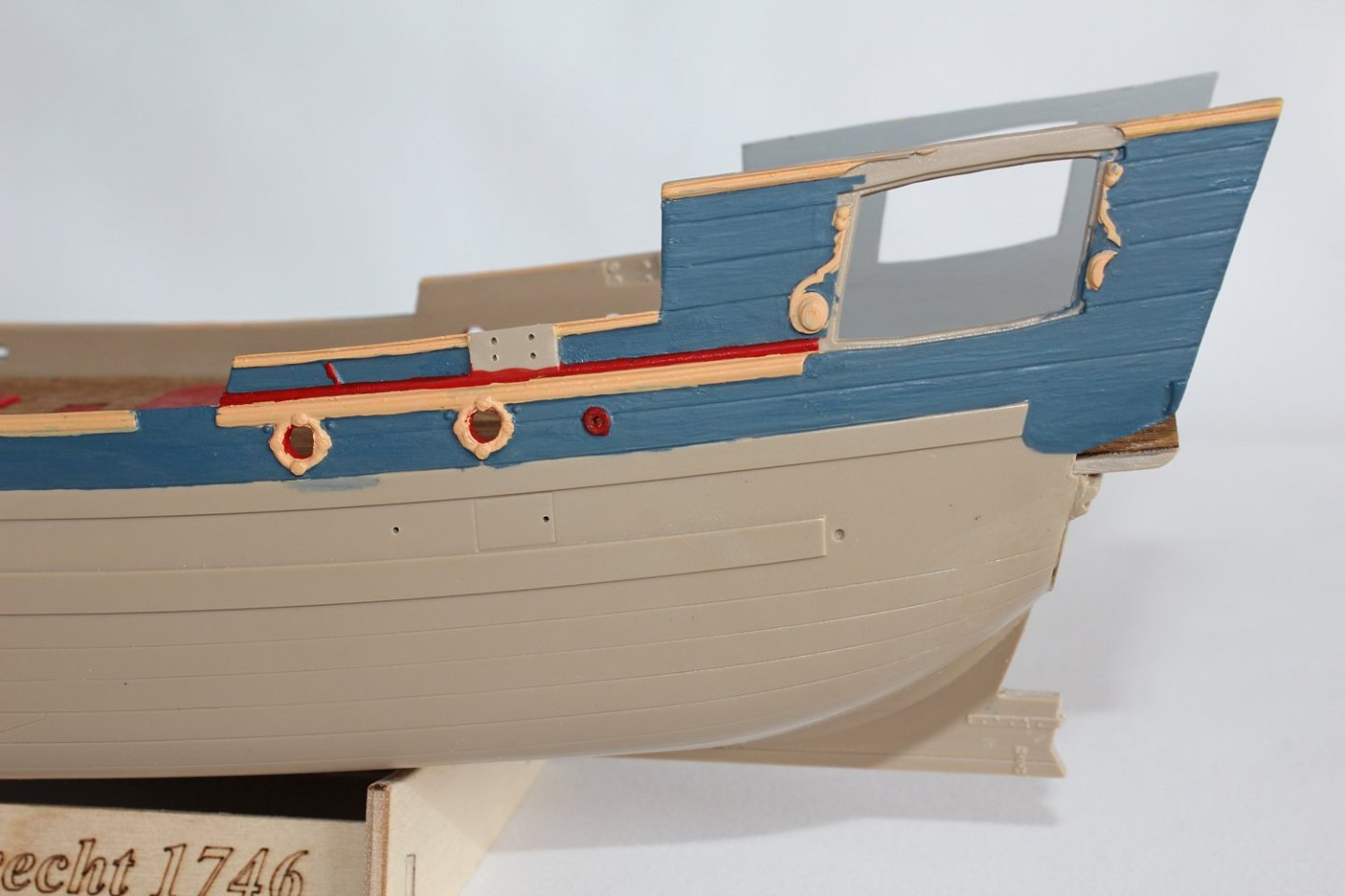
The directions indicate adding the sternpost and rudder at this point. I did and the rudder was promptly broken off, so this will be added at a later point. The fit between the sternpost and the hull required a lot of filling. The stern assembly was partially painted off the model and then installed. I don’t know whether the problem was myself or the kit but the rudder opening in the transom did not center on the sternpost. The bulkhead and quarter badges were painted off the model and installed. Veneer was glued to the quarter deck and installed. This would have been a painted deck, not natural wood, on the actual vessel and is painted on the reproduction. On Utrecht there is a painted metal plate on the stem. This was used as an anchor for a mast stay and bowsprit lashing. This was provided as two photoetch parts which simply needed folding and nailing to the stem. It was well-shaped but was made from a white metal that did not like to bend well. Since this is painted, I would use the provided triangular piece but replace the larger piece with something more malleable, such as softened brass or copper. The rest of the stem parts were installed next. The head timbers were molded to the top head rail. This was glued to the lower rail and installed. The starboard head rail/timbers were nicely molded and fit reasonably well. The port side had molding problems; the foremost head timber was missing and the middle one was misshapen. The figurehead is a resin casting to which a brass crown is added after painting. The only problem is that it looks quite different from the figurehead of the replica Utrecht. The body is realistic but on the replica figurehead, the lion looks fierce and the kit version looks comedic. A crown is molded onto the resin fitting and looks better than the applied brass crown. The picture on the left is the replica figurehead.


-
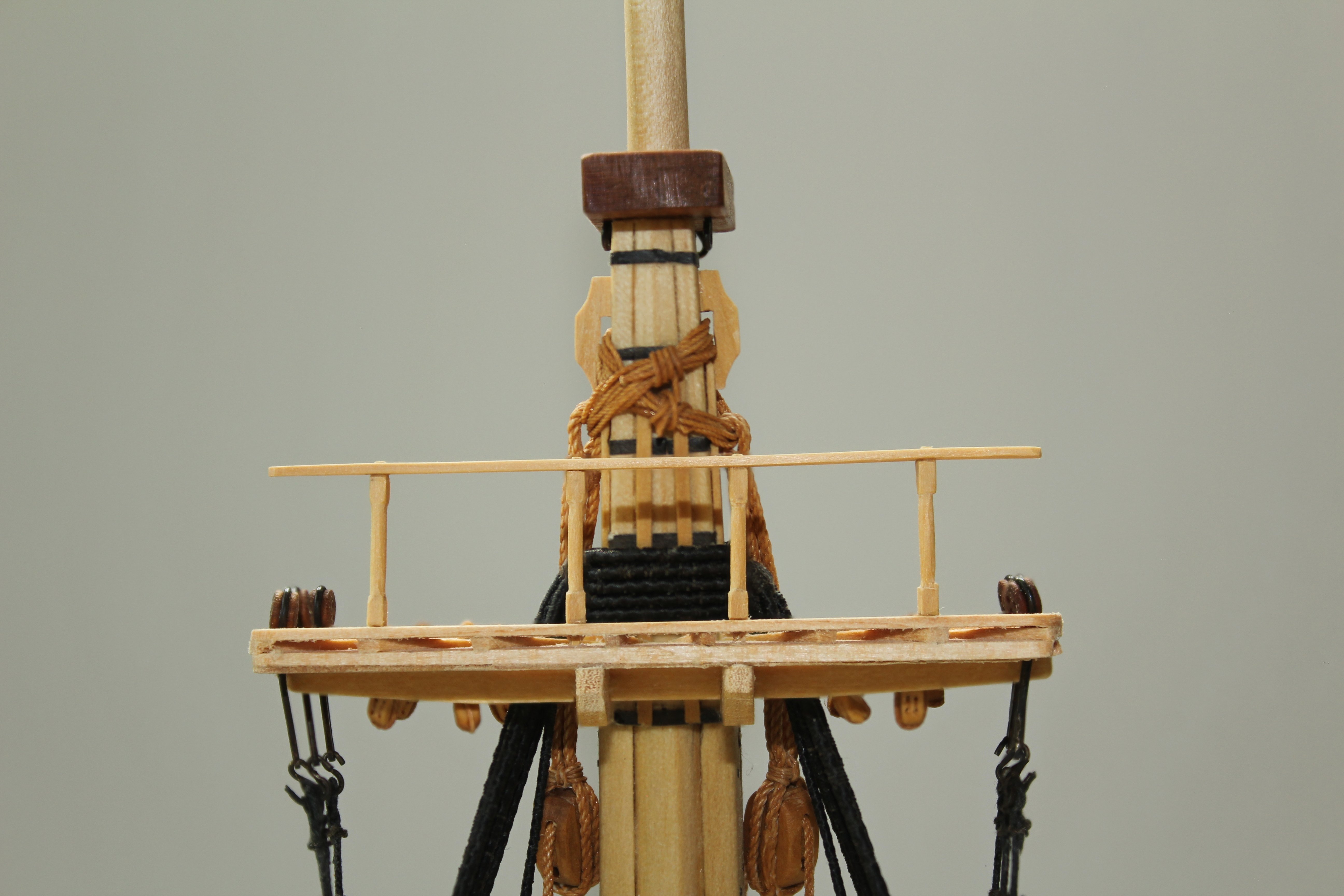
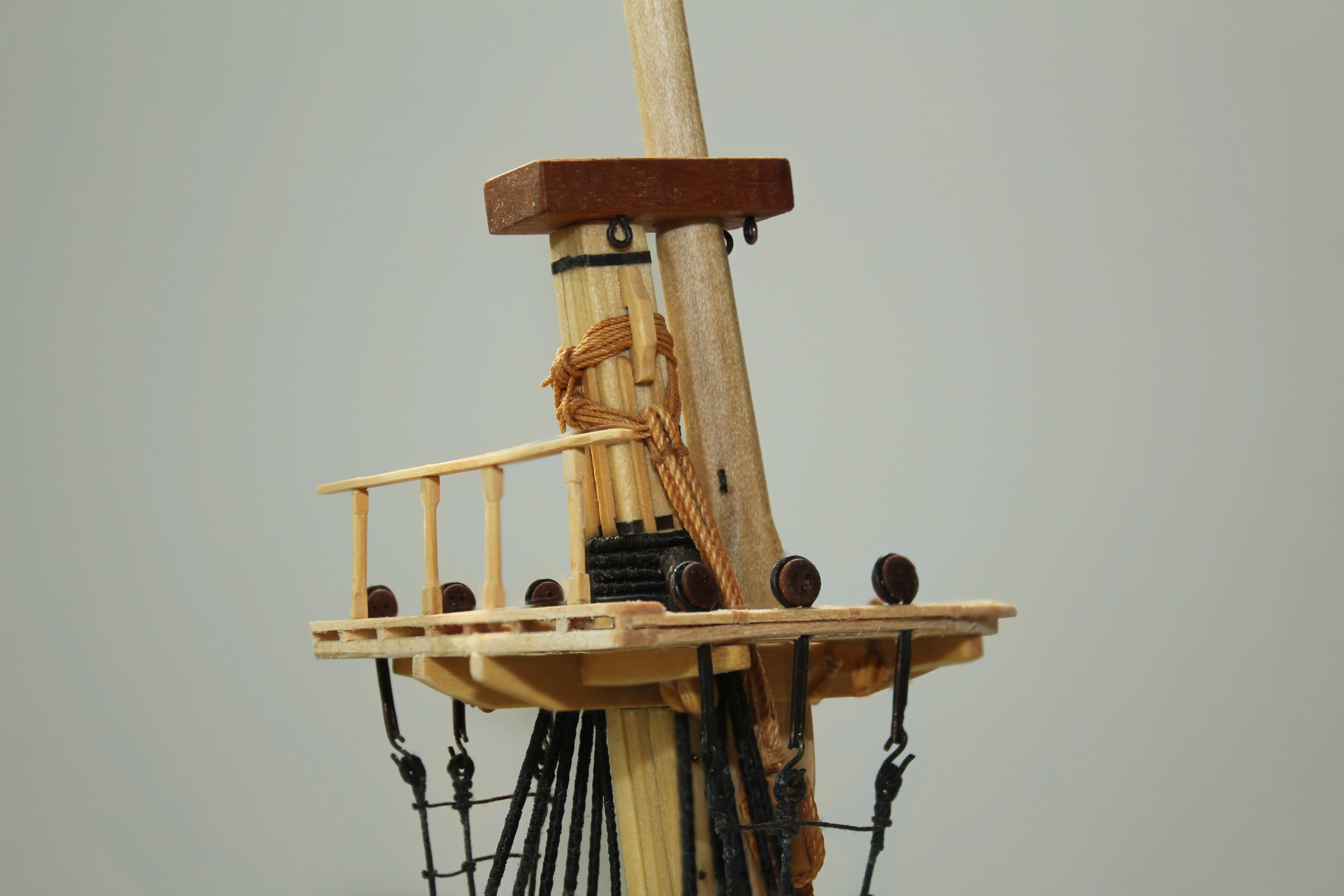
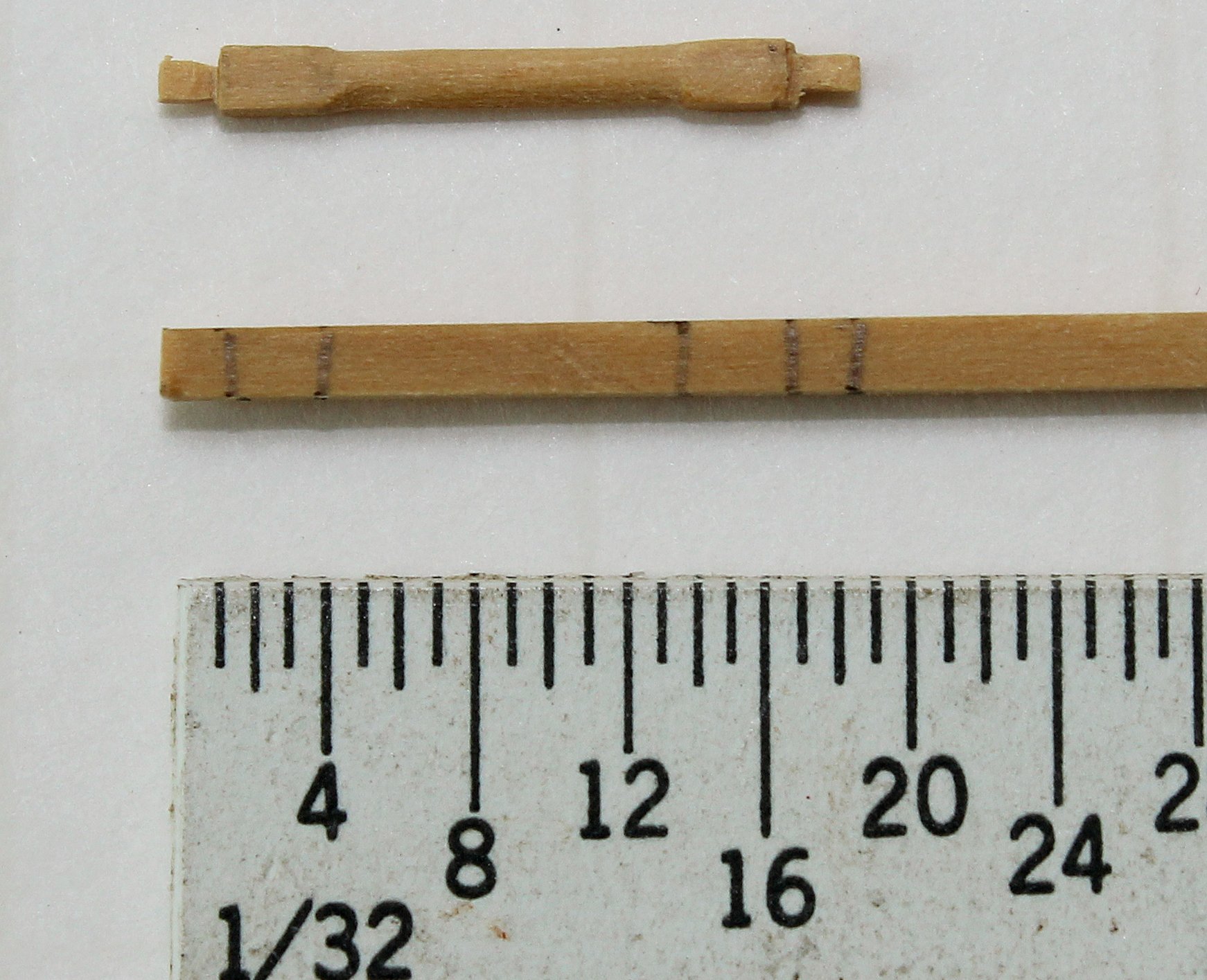
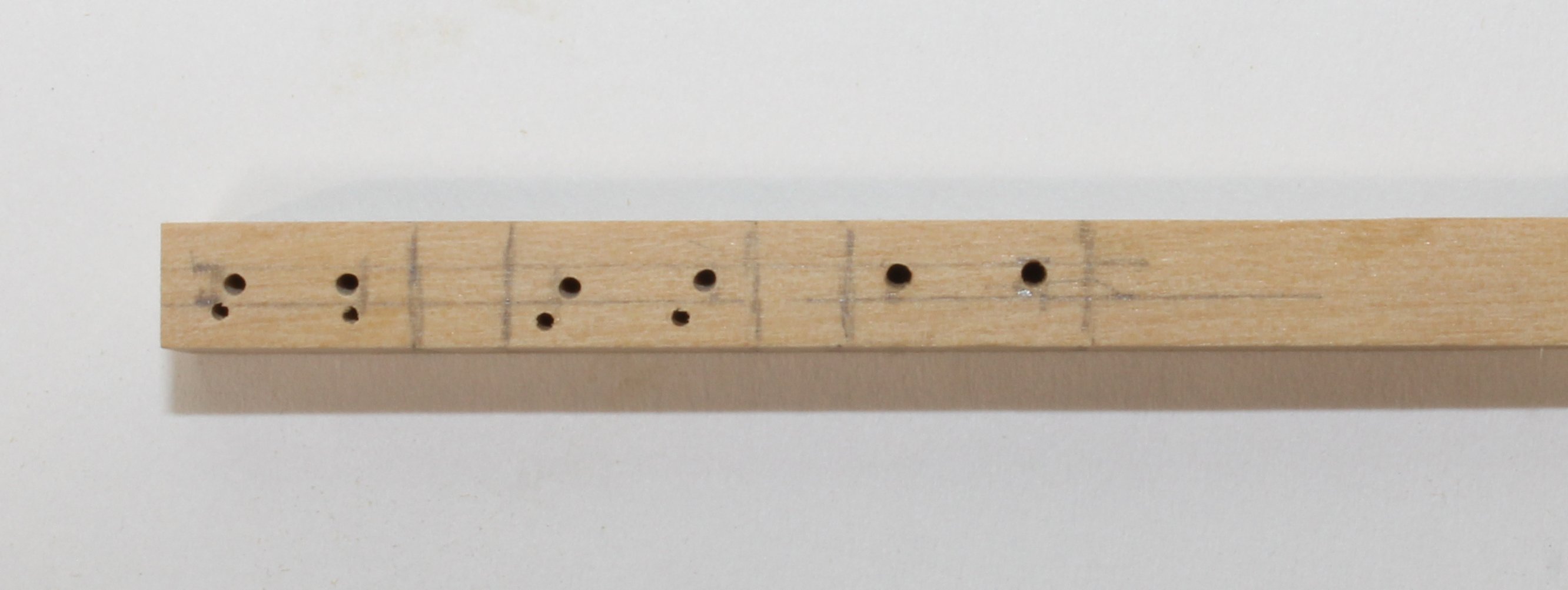
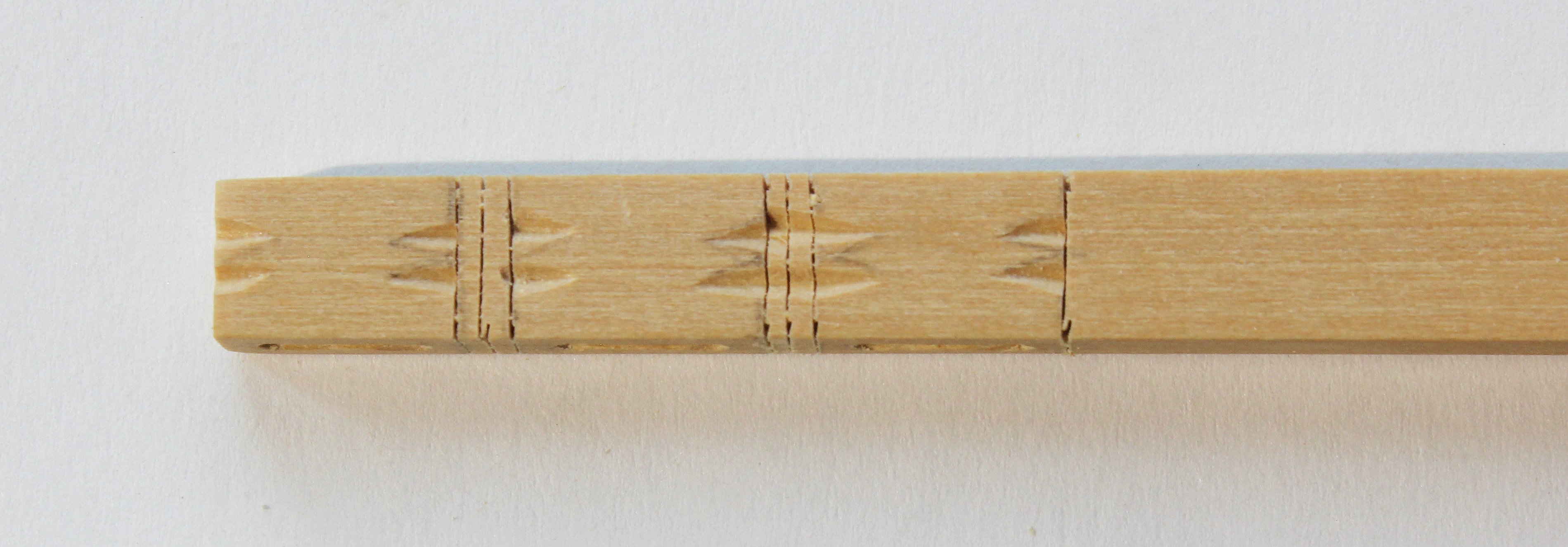
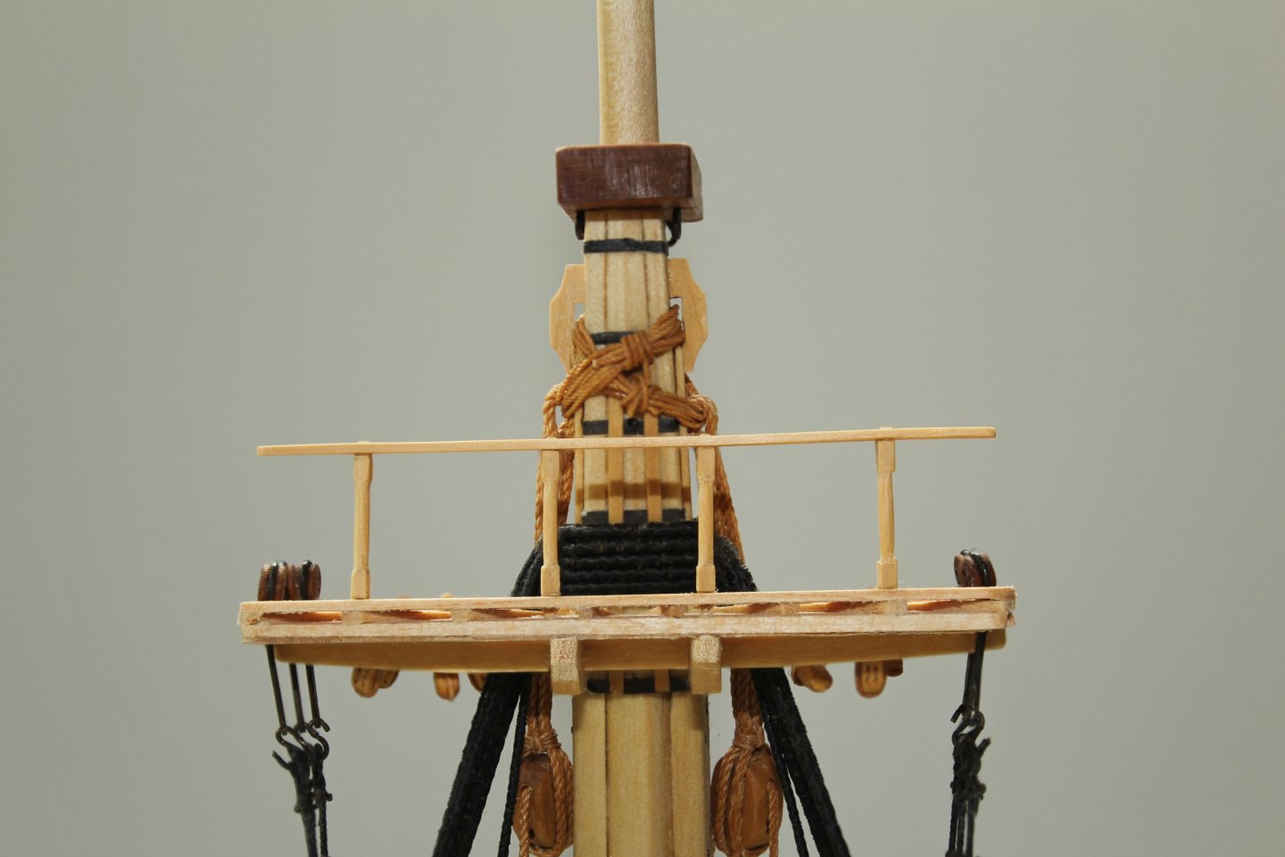
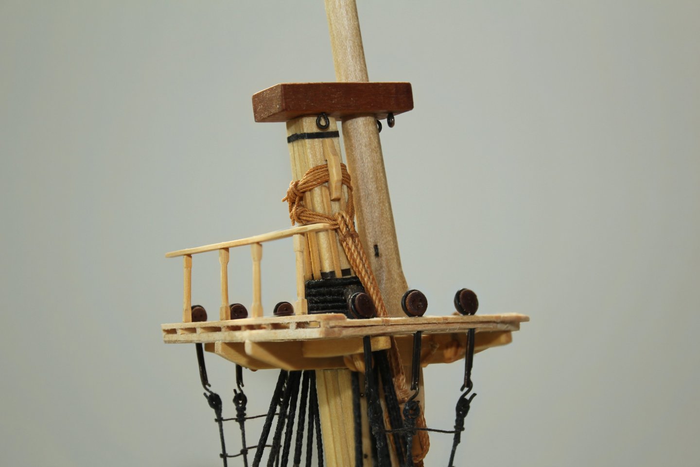
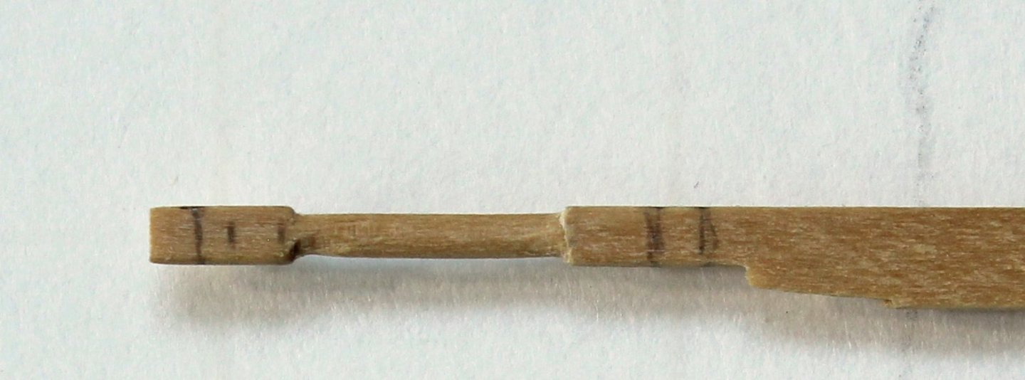
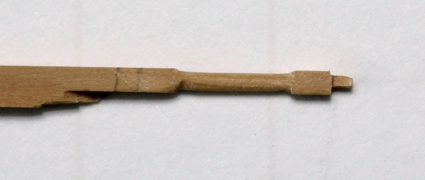
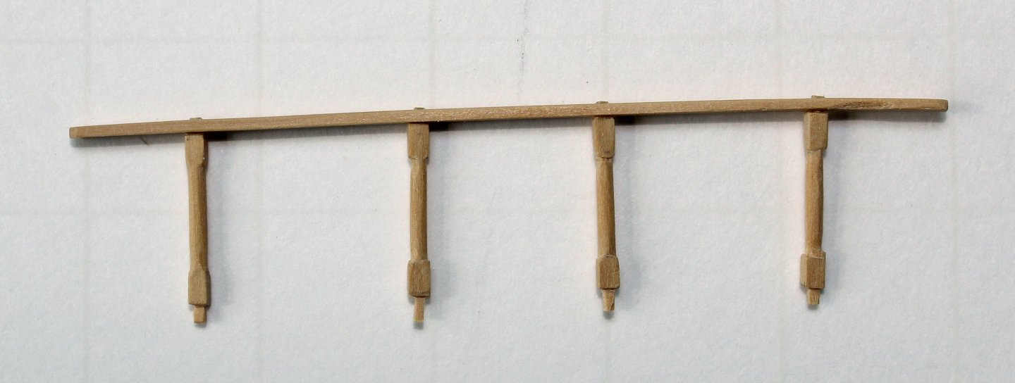
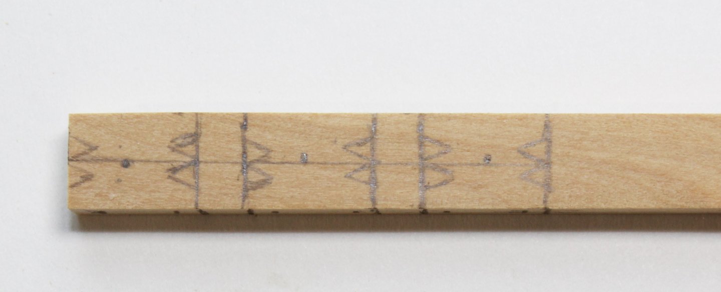
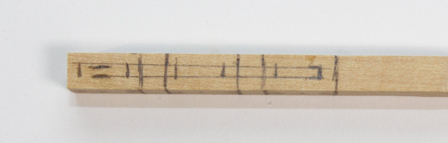
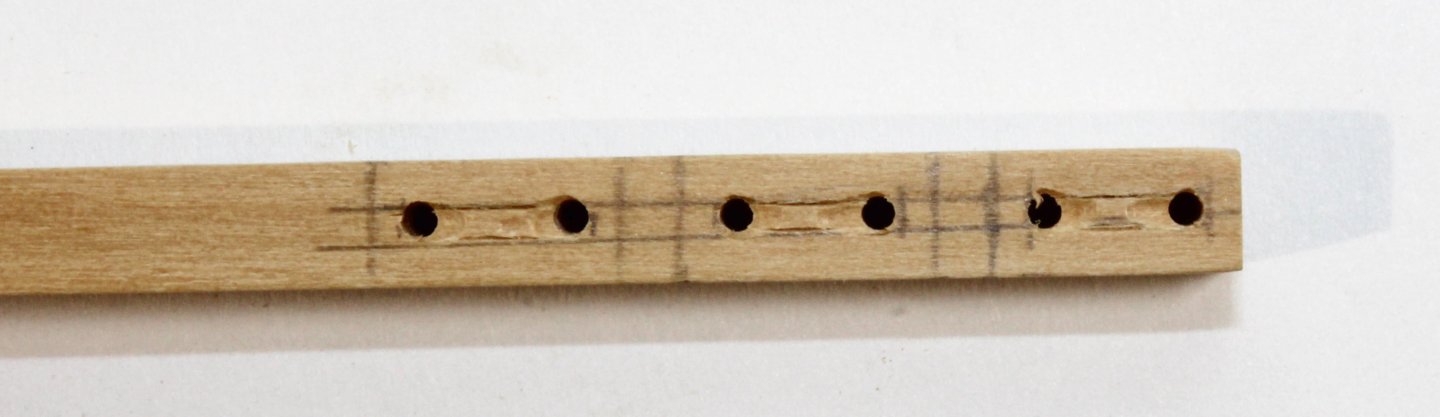
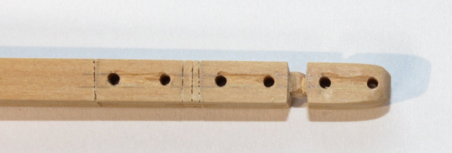
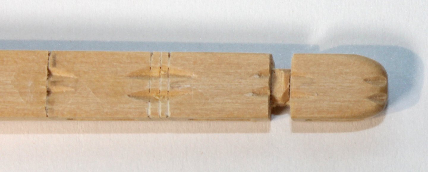
To prevent damage, the top rail was made last. There are four balustrades that fit into the holes previously made in the top and a top rail. The rail extended almost to the edges of the top and is 4” wide. This was cut from 1/32” sheet wood and the edges were smoothed over. The rail was placed on the top’s gunwale and the locations of the balustrade holes were transferred to it. The balustrades are two feet long and 2 inches square. The two ends of the balustrade are square and the center section is round. You can see the transition marks for the top and bottom pins, and between the square and round sections drawn onto the wood. I used an 11 blade, files and sandpaper to round the center section. The transition from square to round was shaped with a half-round file. The end pins are square. The balustrades were inserted into the rail after enlarging the drill holes. Then they were glued into the holes in the top. The rail is angled 90 degrees to the water line. Once dry, the protruding pins were sanded flush with the rail. As a final step, I applied mahogany veneer to the exposed frames. All that was left was to clean things up. Thank you for following along!


- 80 replies
-
- 22
-
-

-
- rigging/masts
- NRG
- (and 2 more)
-
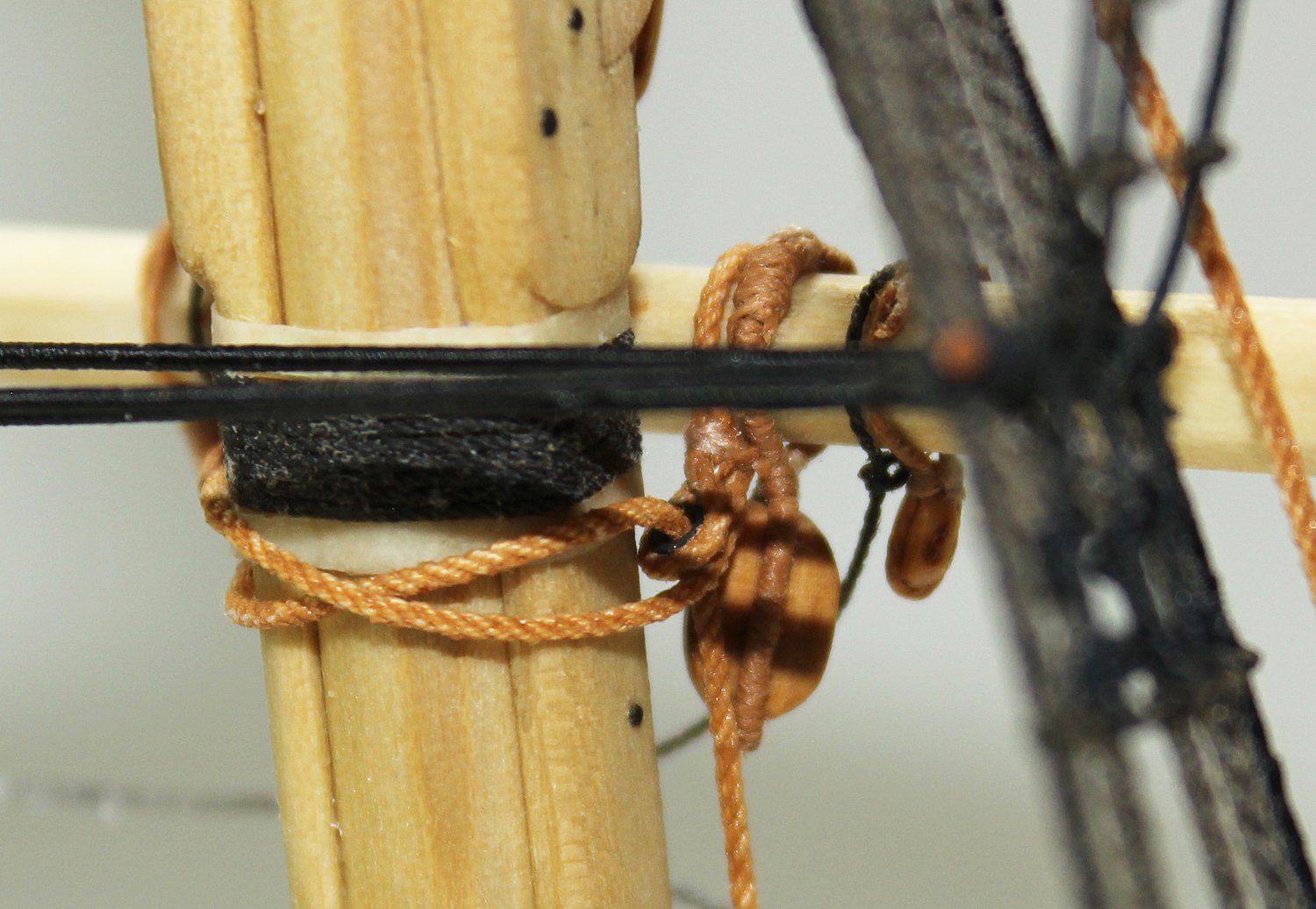
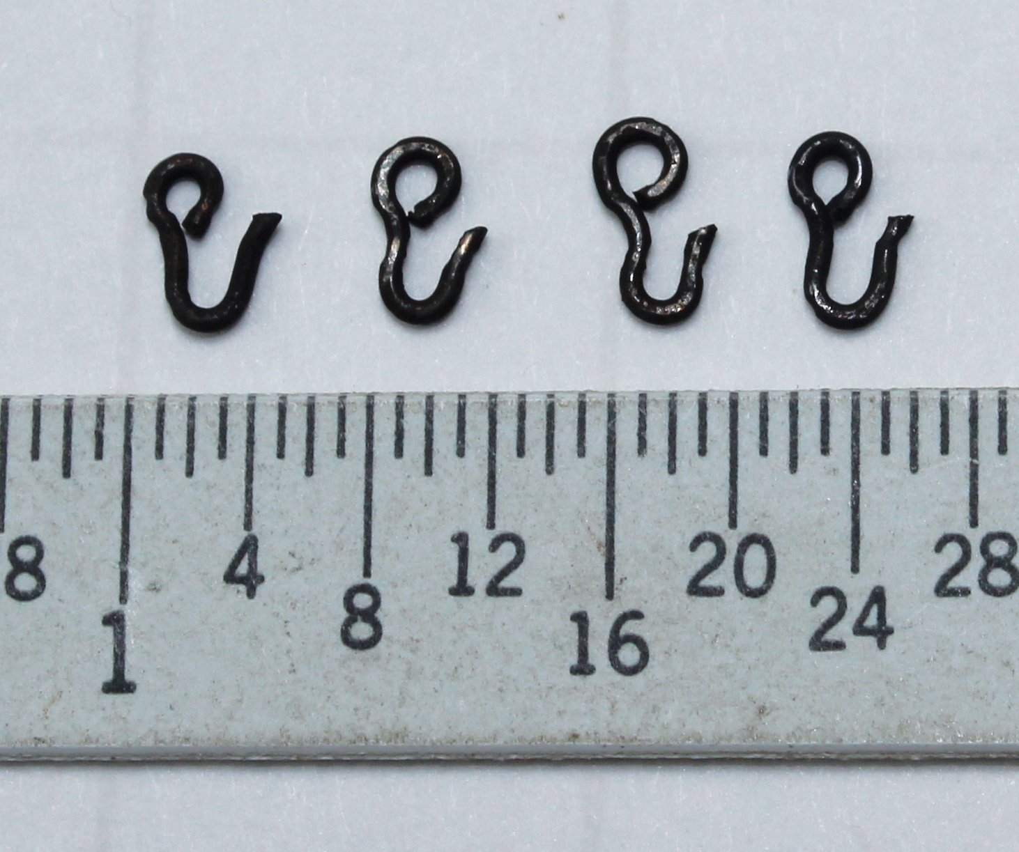
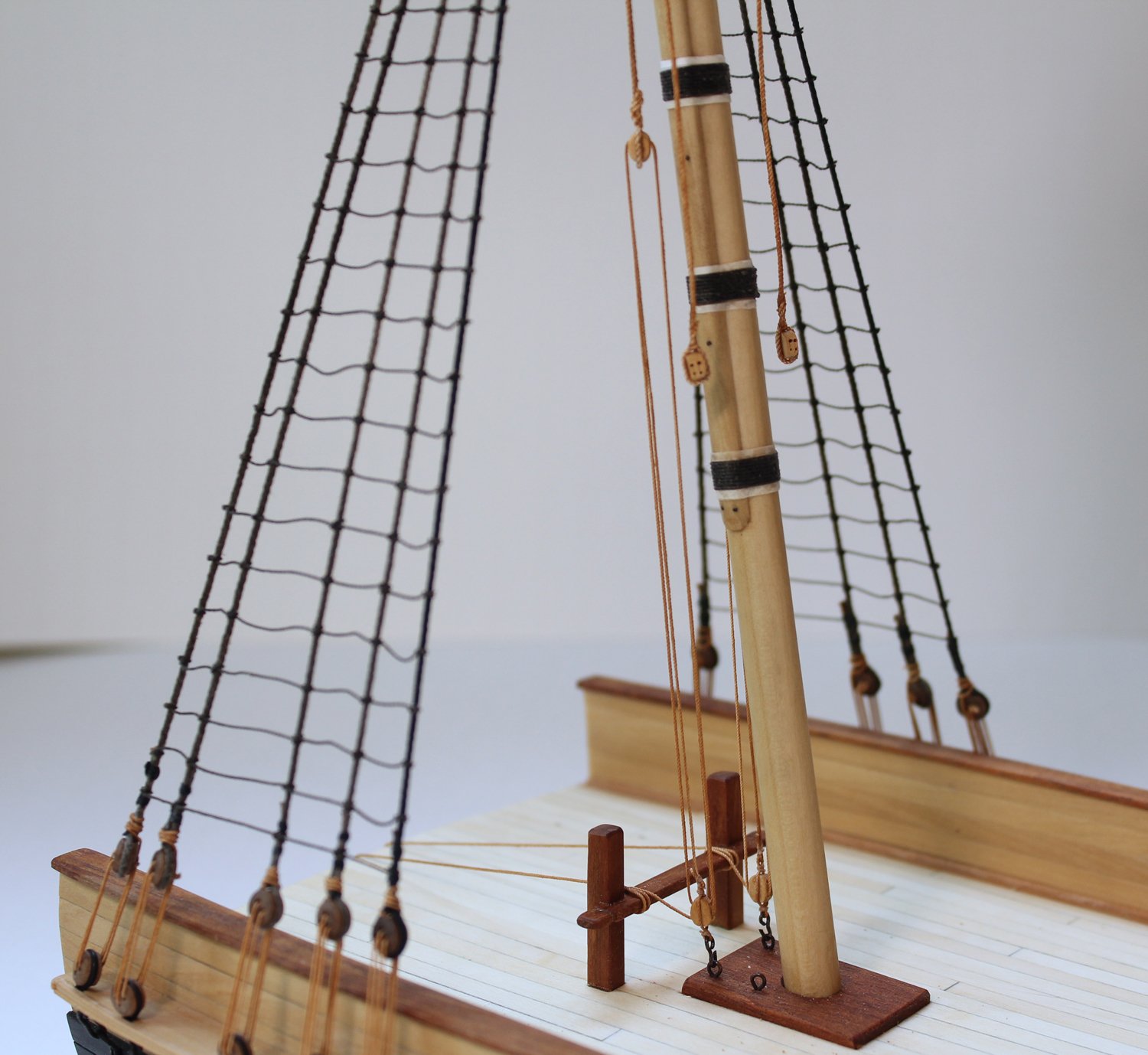
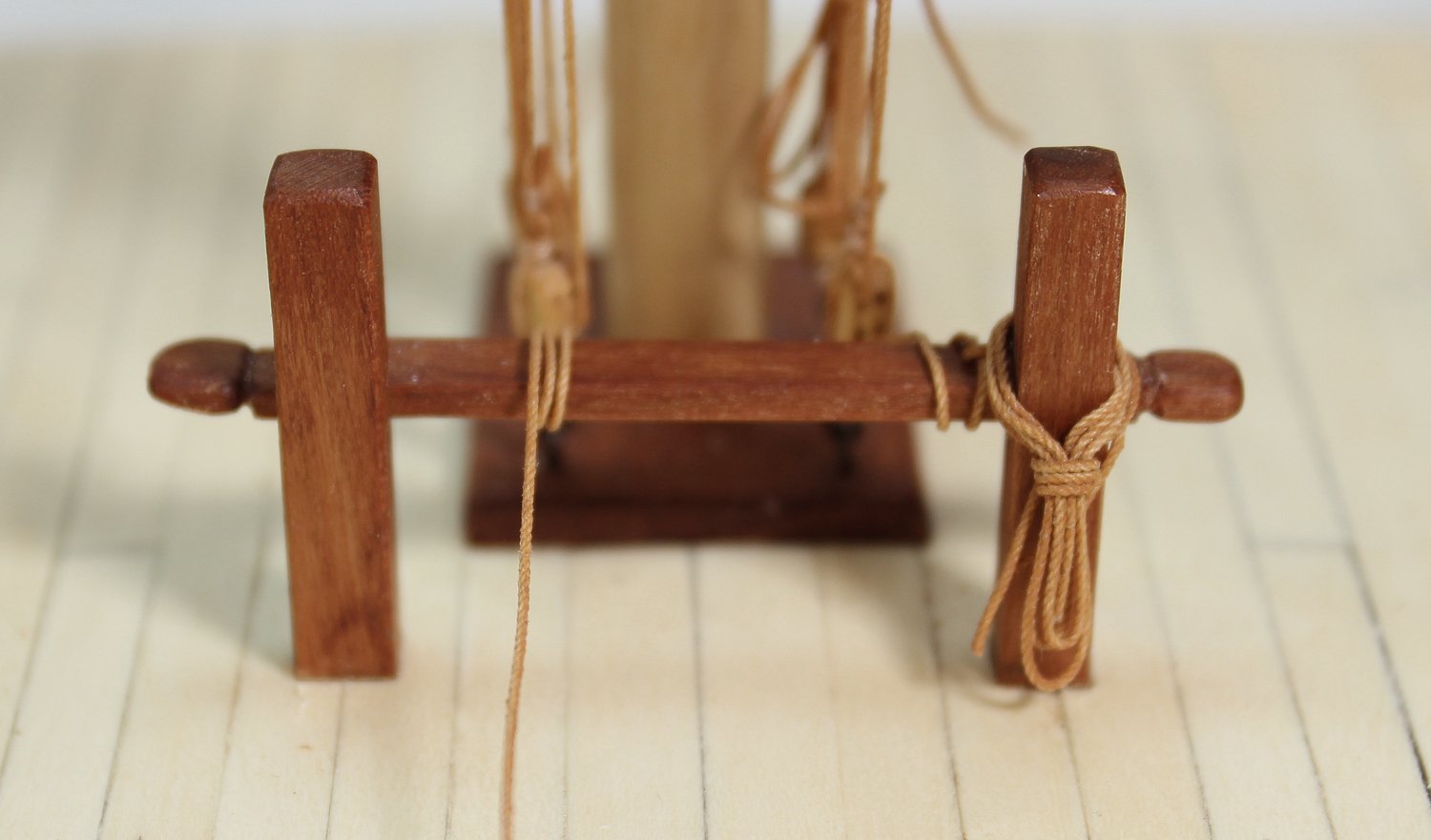
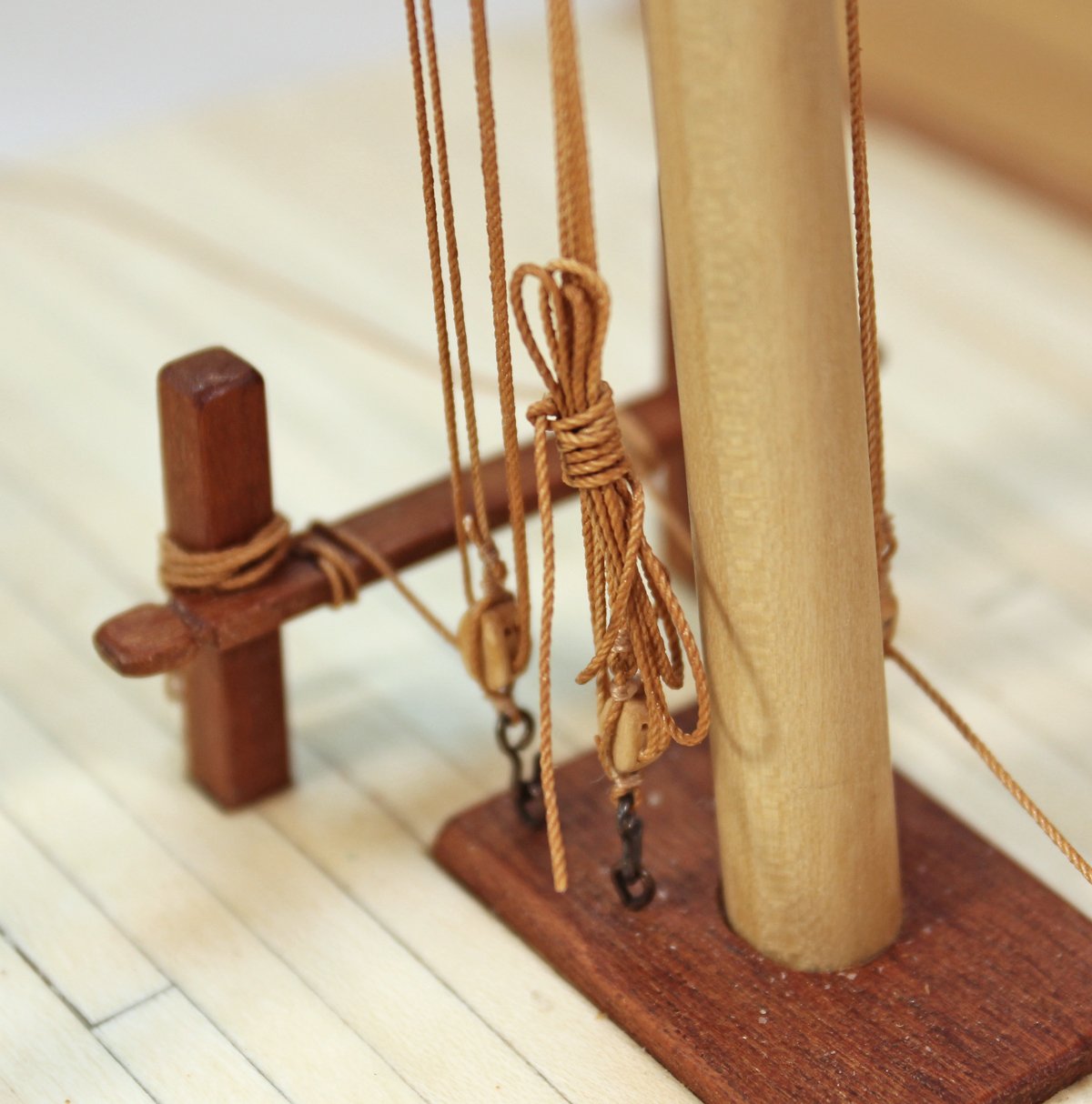
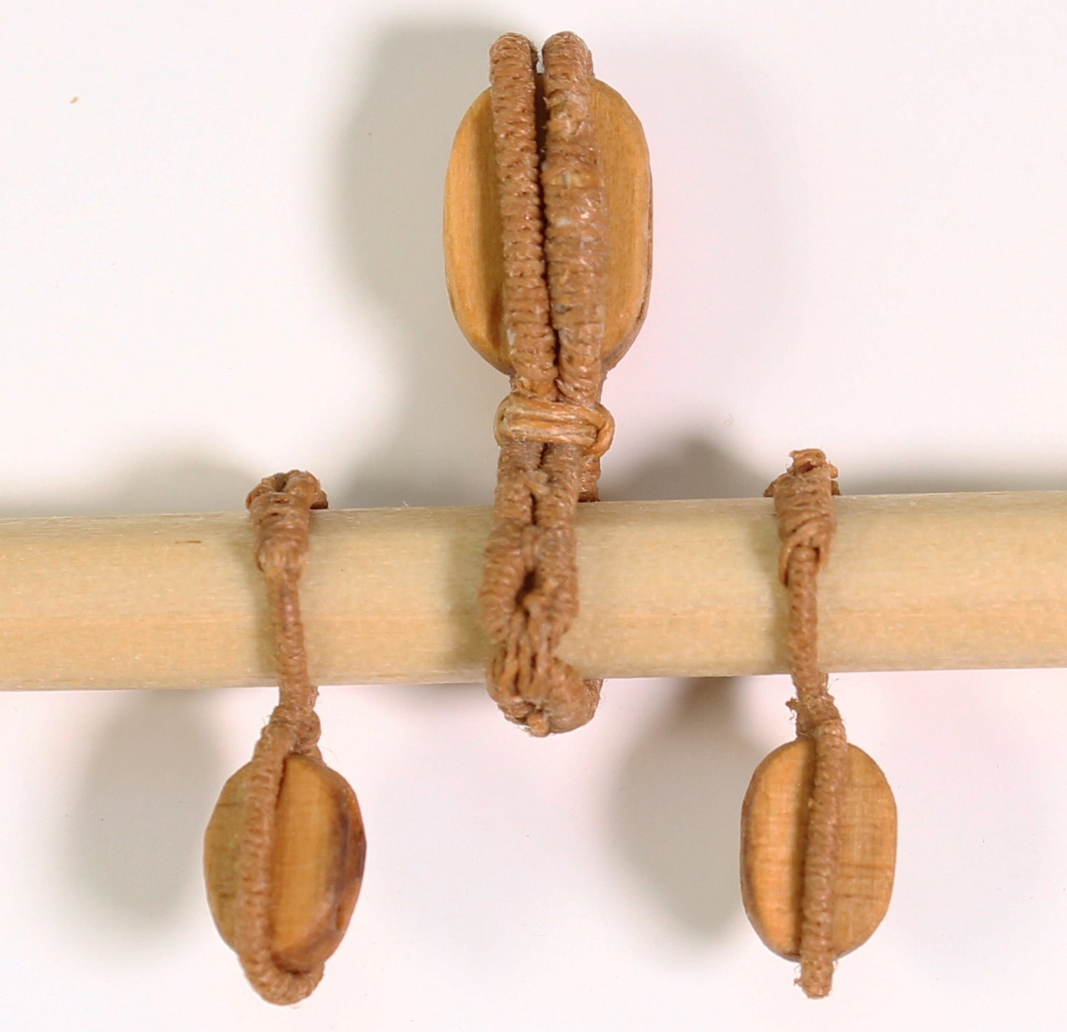
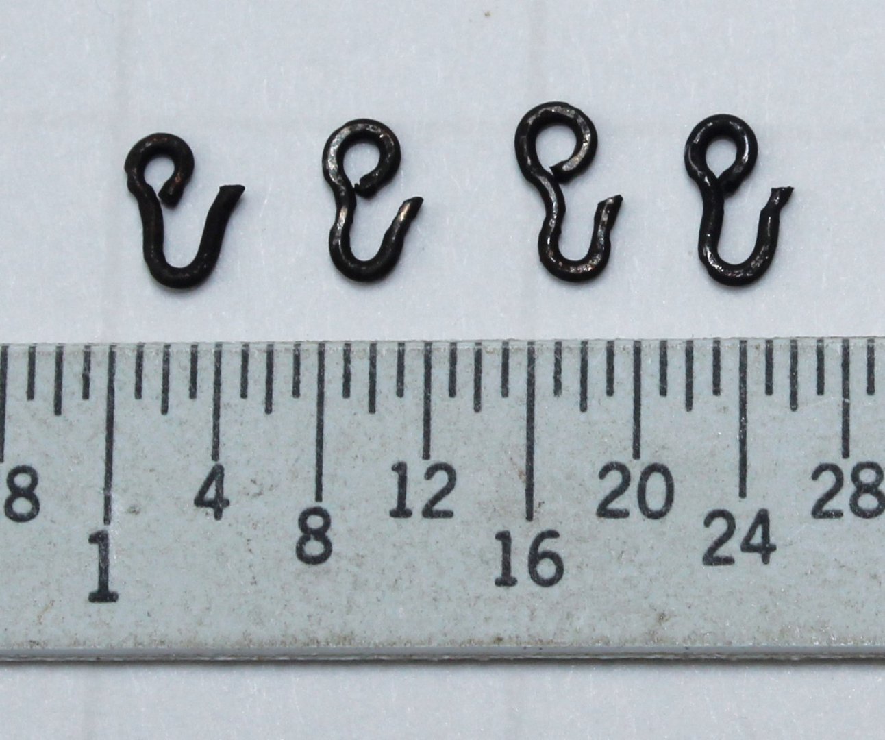
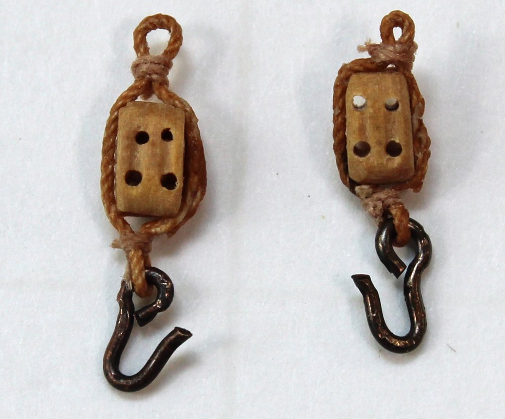
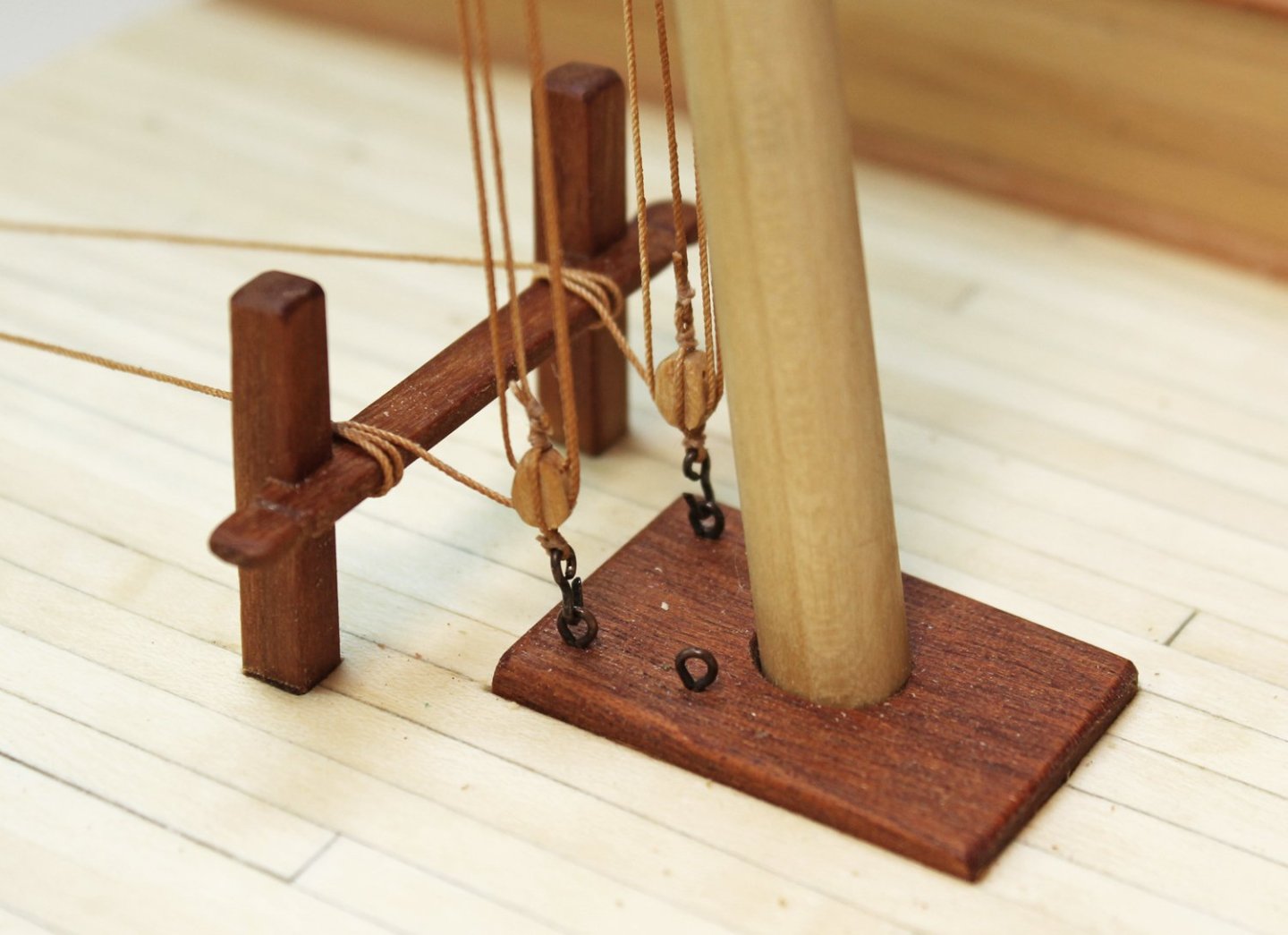
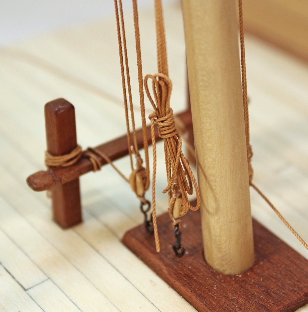
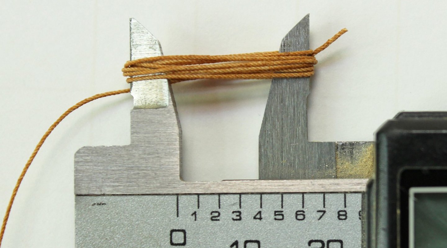
The truss pendants are paired ropes that hold the yard against the mast. These are made from twenty feet of 4” rope with a double block stropped on one end and a thimble on the other. The end with the thimble is seized onto the yard. I spliced a thimble into one end of the line and seized the pendant onto the yard inside the quarter block, keeping the thimble on the aft side of the yard. I rotated the yard 180 degrees to gain better access to the aft side of the yard. Once both pendants were attached to the yard, I ran the line from the starboard pendant through the top of the port pendant thimble; the process was repeated with the port pendant, passing it through the top of the starboard thimble. The result is a crossing of the two lines on the aft side of the mast. Three-millimeter double blocks were stropped on the ends of the pendants for the pendant falls. In the picture below, the outer lines are the jeer tyes and the longer inner ones are the pendants. The lower blocks for the pendant and jeer falls attach to the eyebolts on the mast partners. The strop for the blocks is spliced, with a loop seized at each end. The lower loop is fitted with a hook and the falls will be attached to the upper loop. It took a few tries to make hooks that looked realistic. After they were made, I opened the loop and inserted it into one of the block loops. The rope for the falls passes through the other loop and is spliced to itself to secure it. The jeer tye falls are 2” rope. After securing it to the lower tye falls block loop, the line was passed back and forth through the upper and lower blocks and hooked to the block on the aft eyebolt, adjusting the length of rope as necessary to get a snug but not too tight line. I wrapped the line a few times around the bits and taped the ends to the back of the last frame. This allowed me to easily adjust the tension. The pendant tye falls were rove the same way. The rope for the pendant falls is 1 3/4”. The ends were taped to frame 1. I tightened all the lines and let the model sit for a day to allow the rope to stretch from the tension. The lines were adjusted and retapes them to the frames. The jeer tye falls were finished off by making rope coils to go over the bit pin. I made my coils by taking a piece of line and wrapping it around the jaws of a caliper. The line was removed by closing the jaws. A few turns of line were wrapped around the middle of the coil. Steel states that both the jeer tye and pendant falls tie off to bits. I tied the jeer tye falls to the bits and the pendant falls to itself to prevent the lines from rubbing against each other and to show an alternate way to tie off a line. The rope coils for the pendant falls were made on the model. My rope coil is 3.5’ long and the wrap is 4’ up from the deck. That completes the rigging.


- 80 replies
-
- 18
-
-
- rigging/masts
- NRG
- (and 2 more)
-
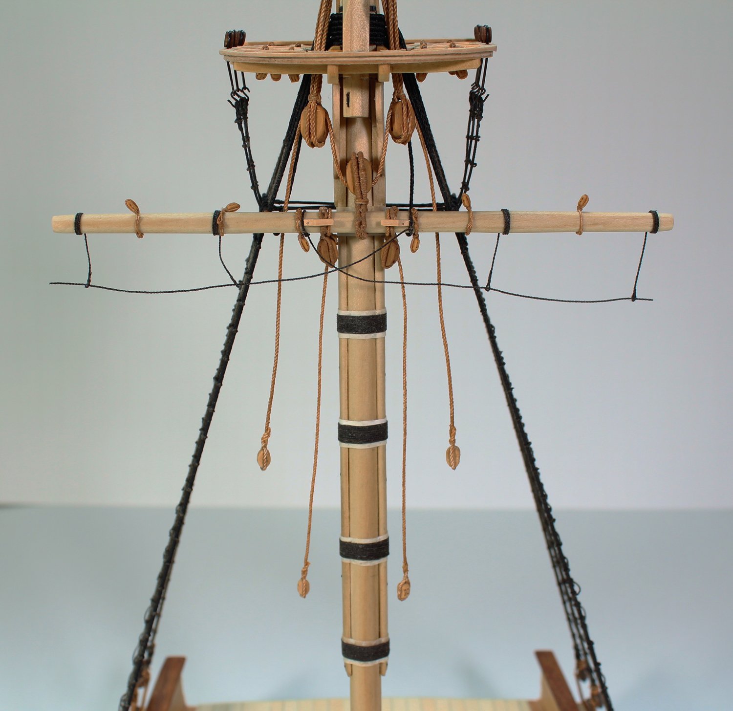
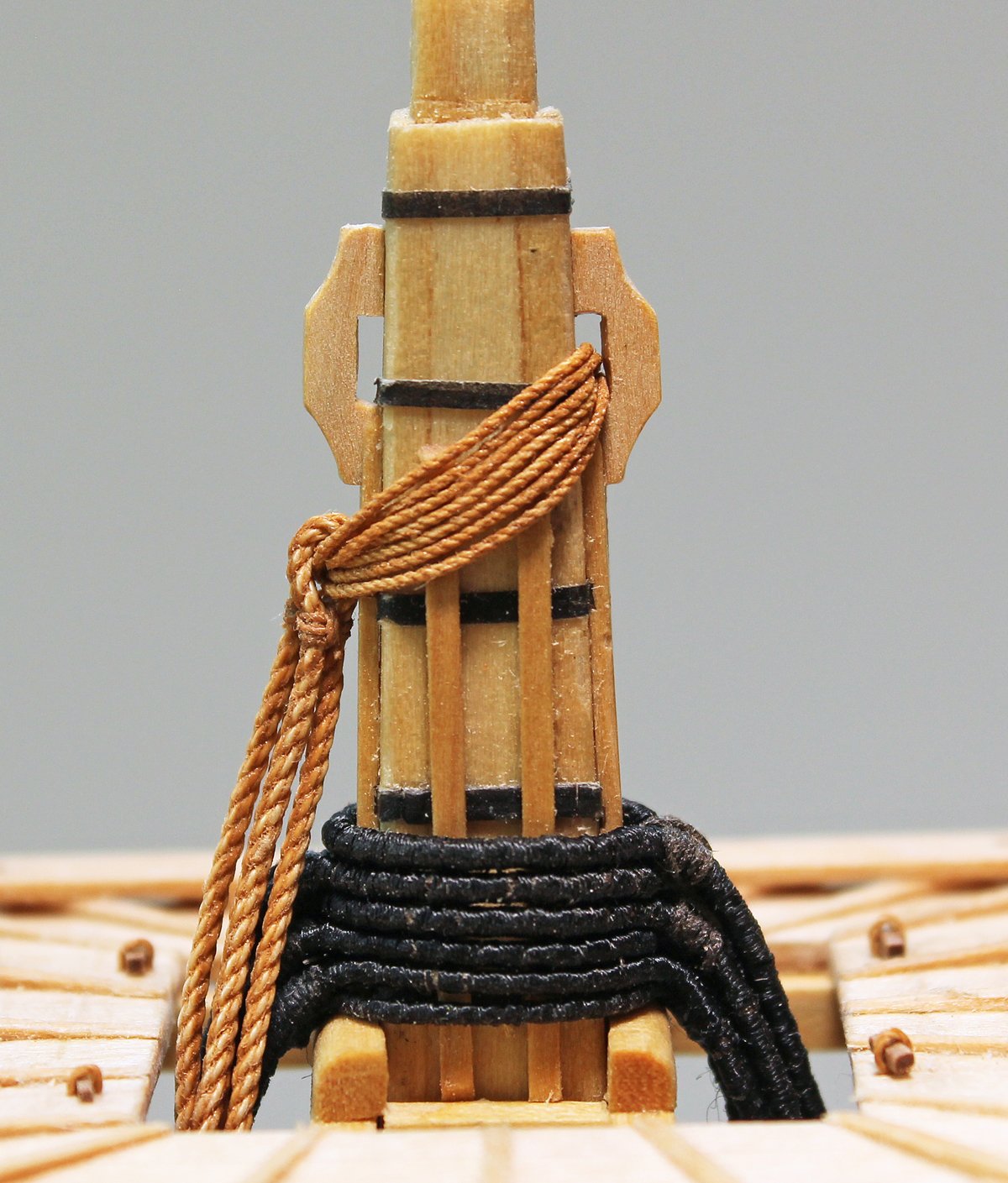
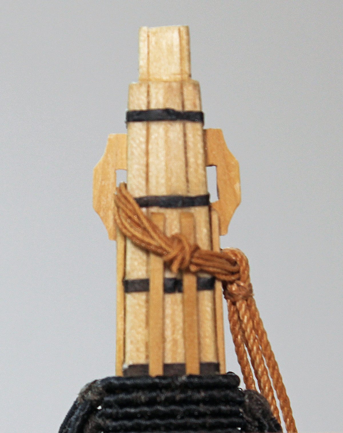
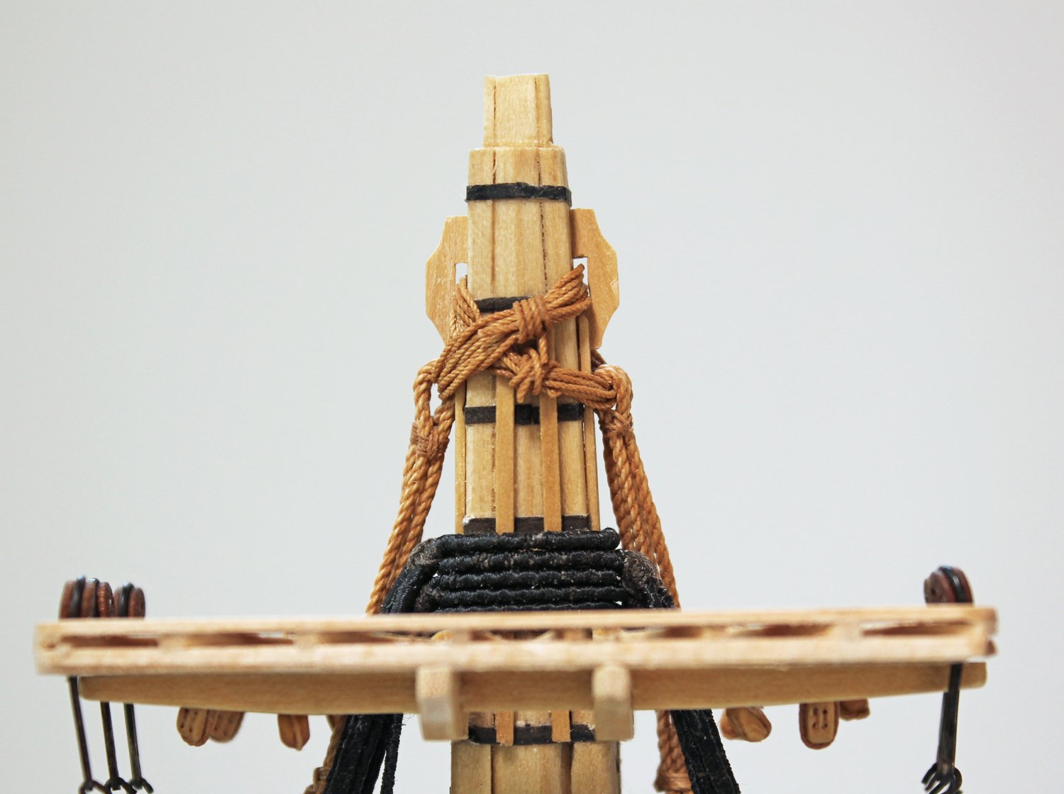
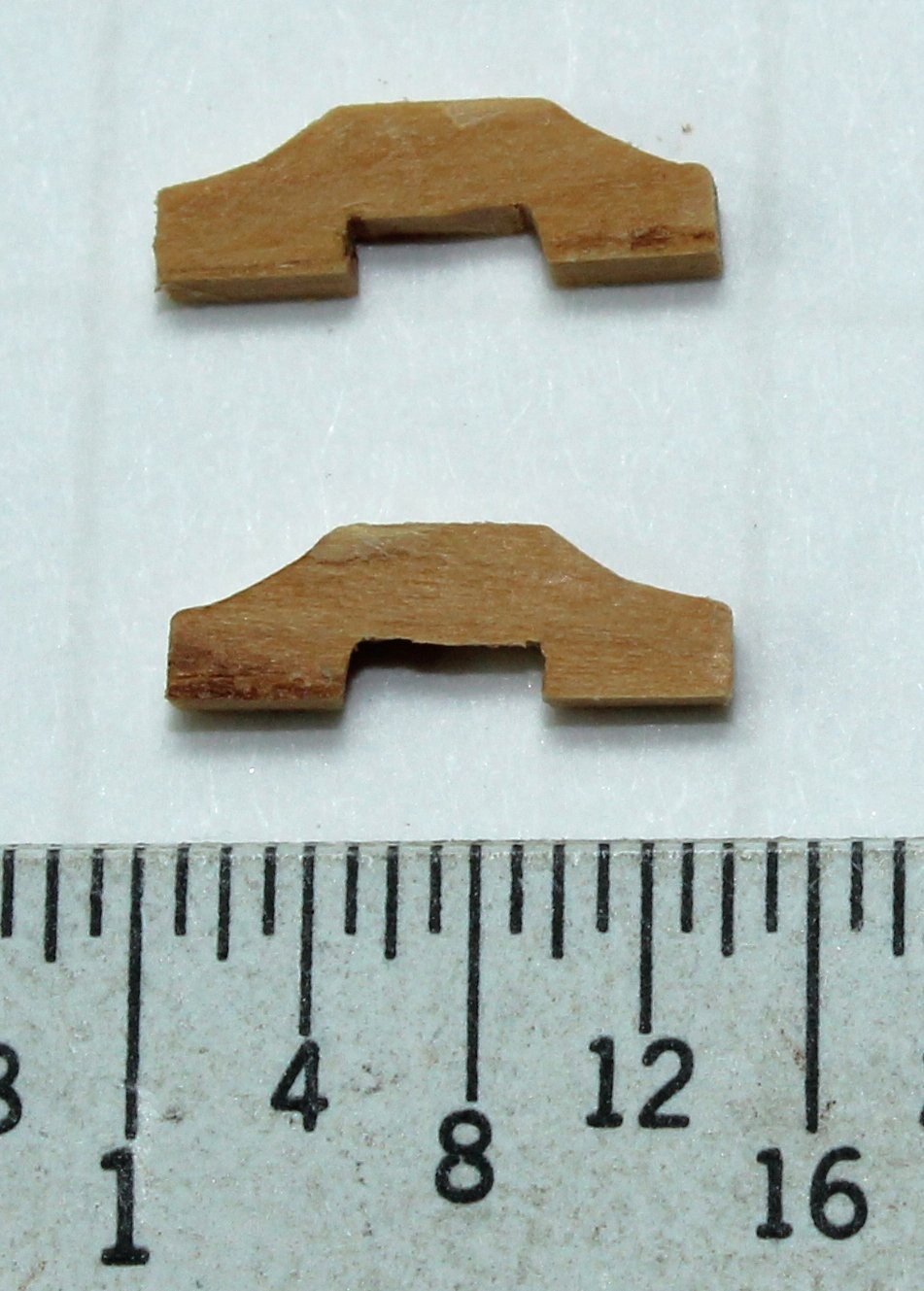
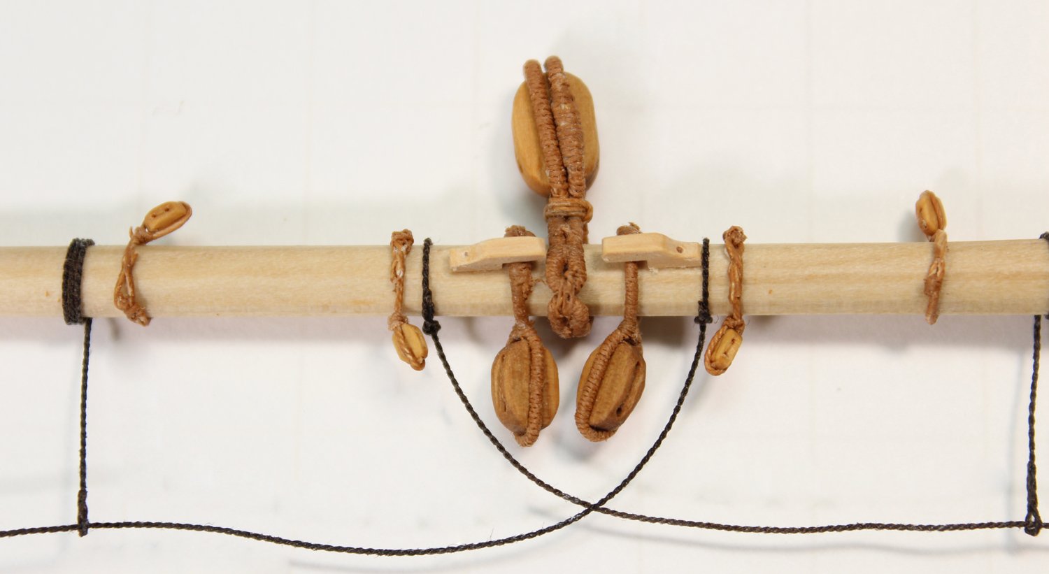
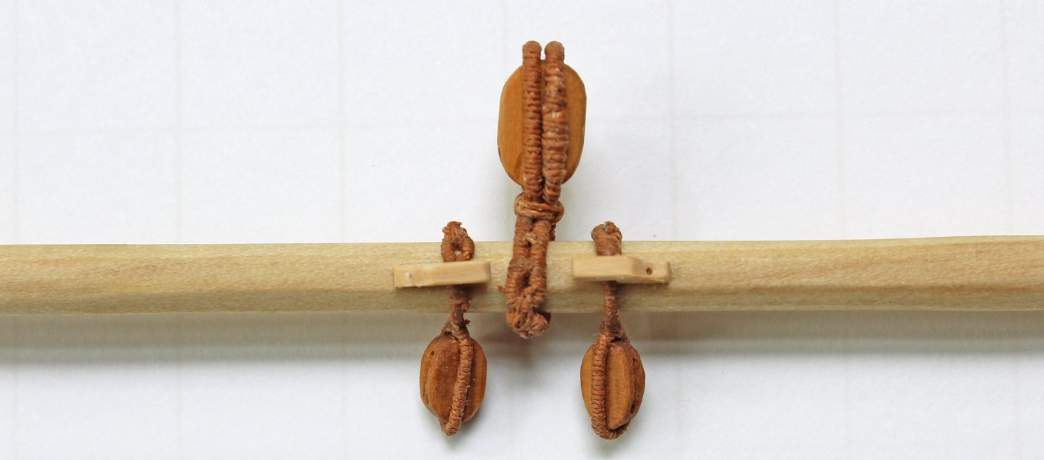
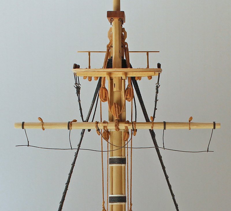
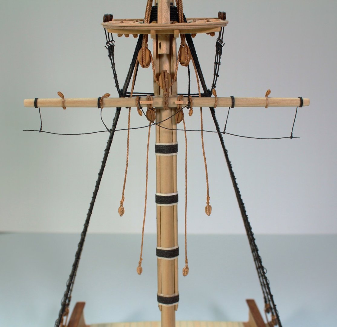
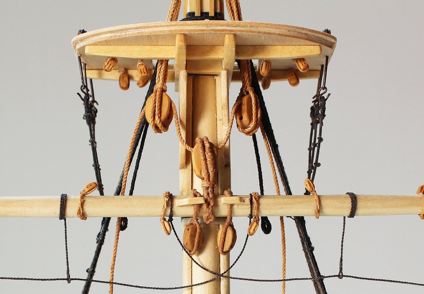
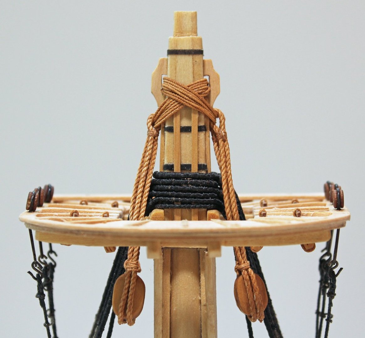
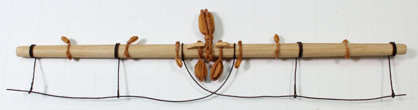
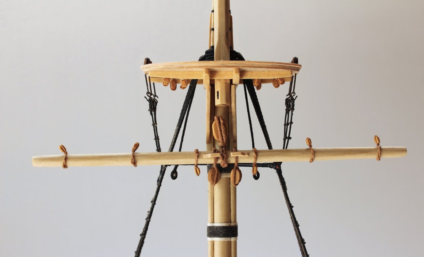
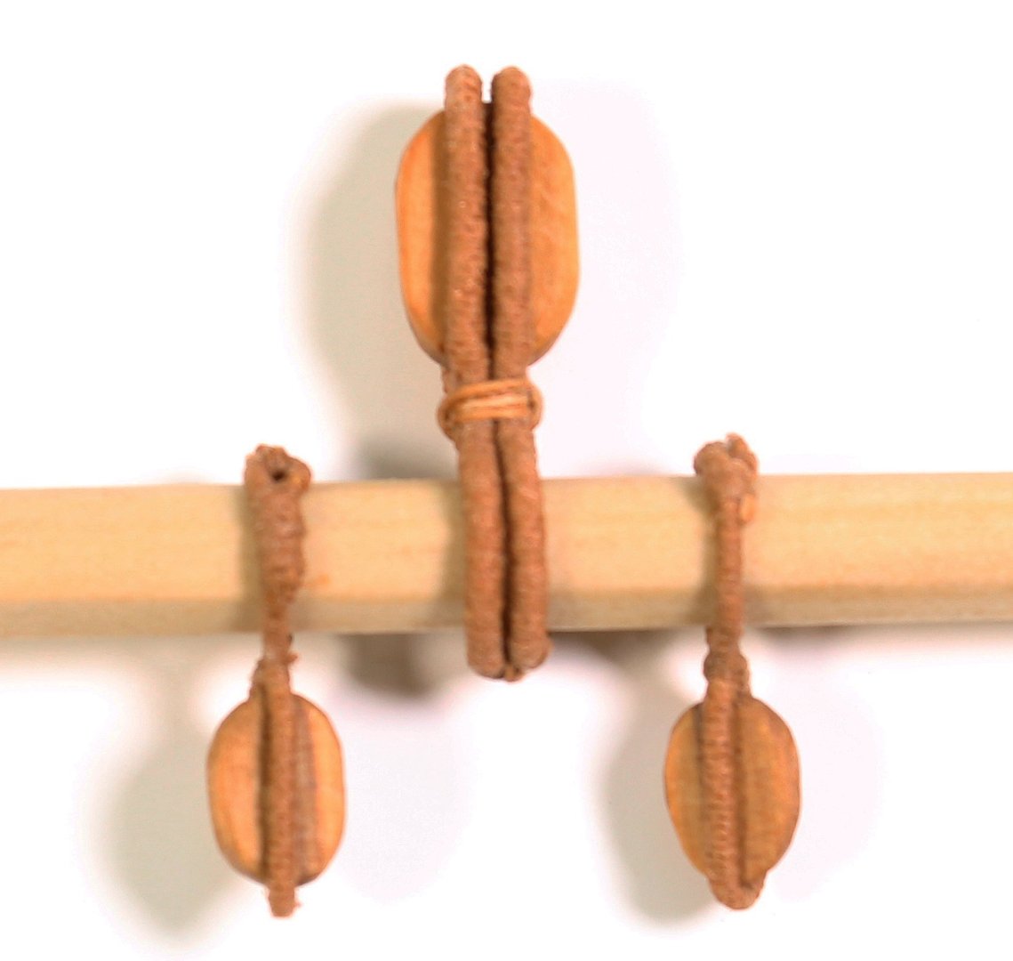
The jeer tye blocks are suspended from the mast head, pass through the opening in the center of the top and hang below the top. A rope, the jeer tye, comes up from below the yard, runs through the jeer tye block, down to the jeer block , up to the other jeer tye block and back down towards the deck. These pictures shows the location of the jeer tye blocks and the jeer tye forming the letter “M”. Cleats are located on either side of the masthead for the lashings that secure the jeer tye strop. These were made the same way I made the yard cleats. The sharp outer edges were rounded over and they were installed onto the side of the masthead between the battens and below the upper metal hoop. The jeer tye blocks have a double strop. Steel states that all block strops greater than 4” are served. These are 17” blocks and would have had 5” strops. However, Antscherl, in TFFM, Vol 4, page 100, shows jeer tye blocks stropped with unserved line. Without a clear direction to take, I chose to leave them unserved. The block hangs below the top a distance equal to the length of the block. These blocks were stropped using the same process used for the other blocks except the two legs are the same length. The block was secured with a throat seizing and loops were seized on both arms. The starboard jeer tye block was installed first. Seven turns of lashing went through the jeer tye loops and the opposite cleat. It was then wrapped around itself and secured on the aft side of the masthead. The port jeer tye block was installed the same way and the lashing was adjusted so the two blocks hunt at the same level. The jeer tye (the line than runs through the three jeer blocks) has a double block for the jeer tye falls on each end. According to Steel, the tye should be the length of the mast, 56 feet. “Falls” describe a pully arrangement with a heavier line (i.e. the jeer tye) stropped to a block with lighter rope running between this block and another block attached to the deck. The easiest way I found to attach the blocks to the tye is to strop a block onto one end of the tye and then pass the tye through one of the jeer tye blocks, down to the jeer and back up through the other jeer tye block. The line was threaded through all three jeer blocks until the jeer tye block came up to the jeer block. This gave me more room to attach the other tye block. I passed the jeer tye back through the jeer blocks until the double blocks were level with each other.


- 80 replies
-
- 14
-
-
-
- rigging/masts
- NRG
- (and 2 more)
-
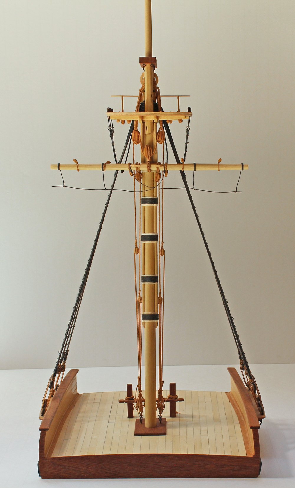
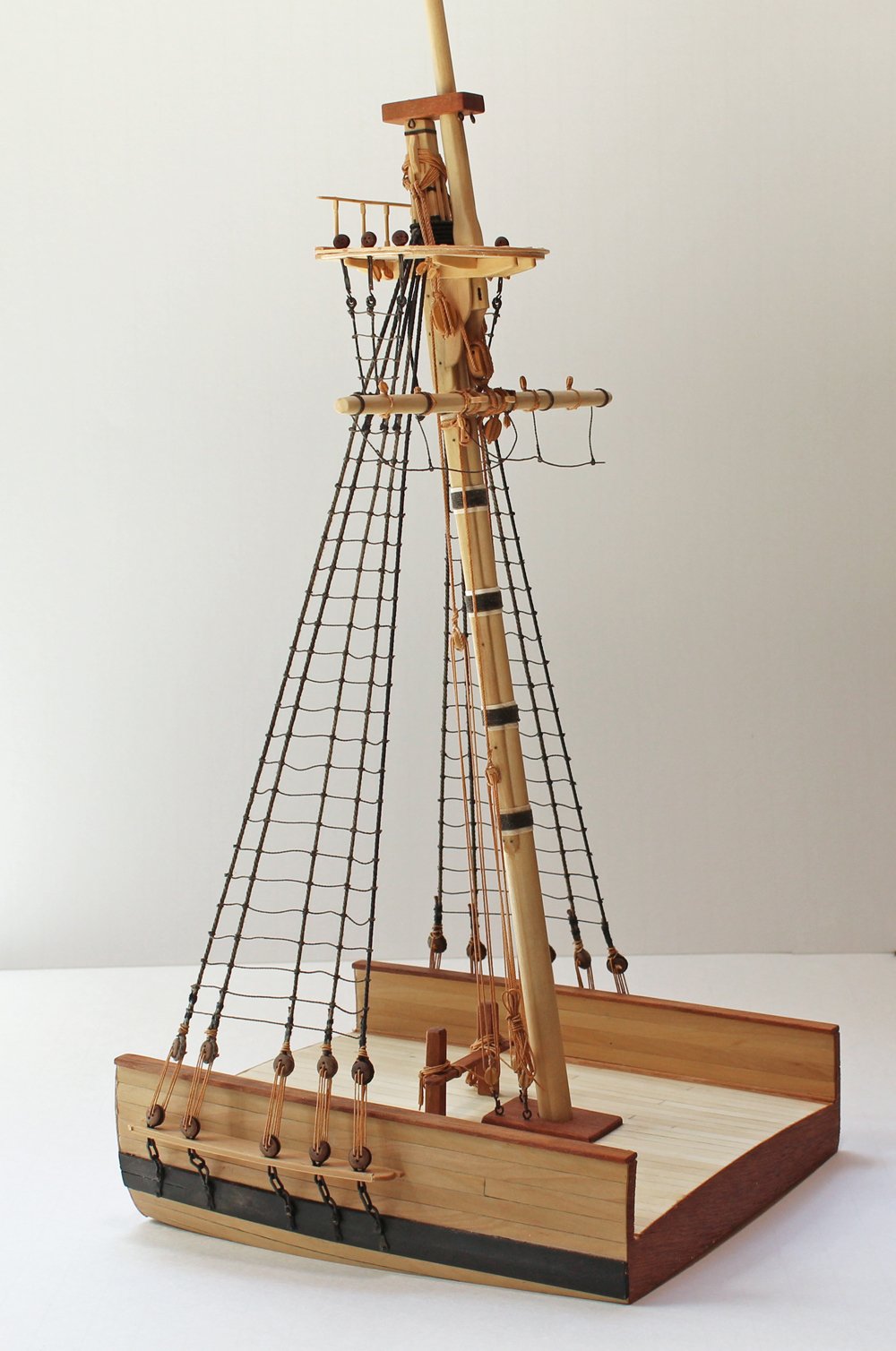
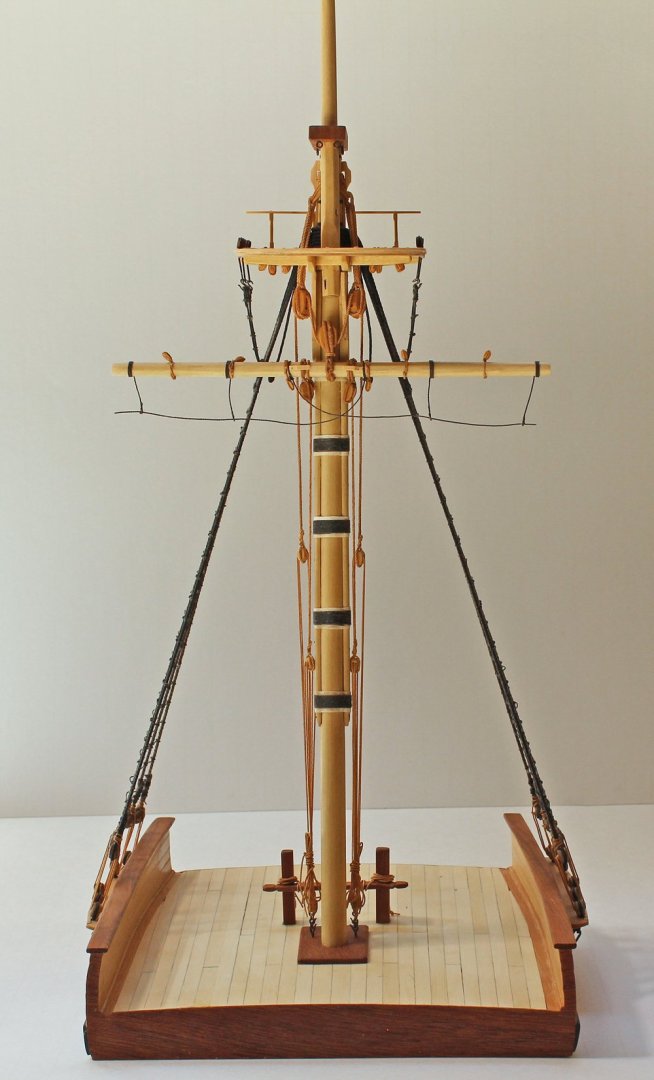
The NRG Masting and Rigging Project is now available for purchase in the NRG store. https://thenrgstore.org/collections/plans-and-projects/products/masting-and-rigging-kit The purpose of this kit is to teach the novice and intermediate model builder the basics of how to mast and rig a ship. The subject for this project is a waterline 1:48 scale cross-section of a late eighteenth-century British sloop of war. All the materials necessary to build the kit are included. We are pleased to provide the highest quality materials available. All of the line is from our sponsor Ropes of Scale. There are no square blocks in this kit! For more details about the model, follow the build log.
- 1 reply
-
- 7
-
-
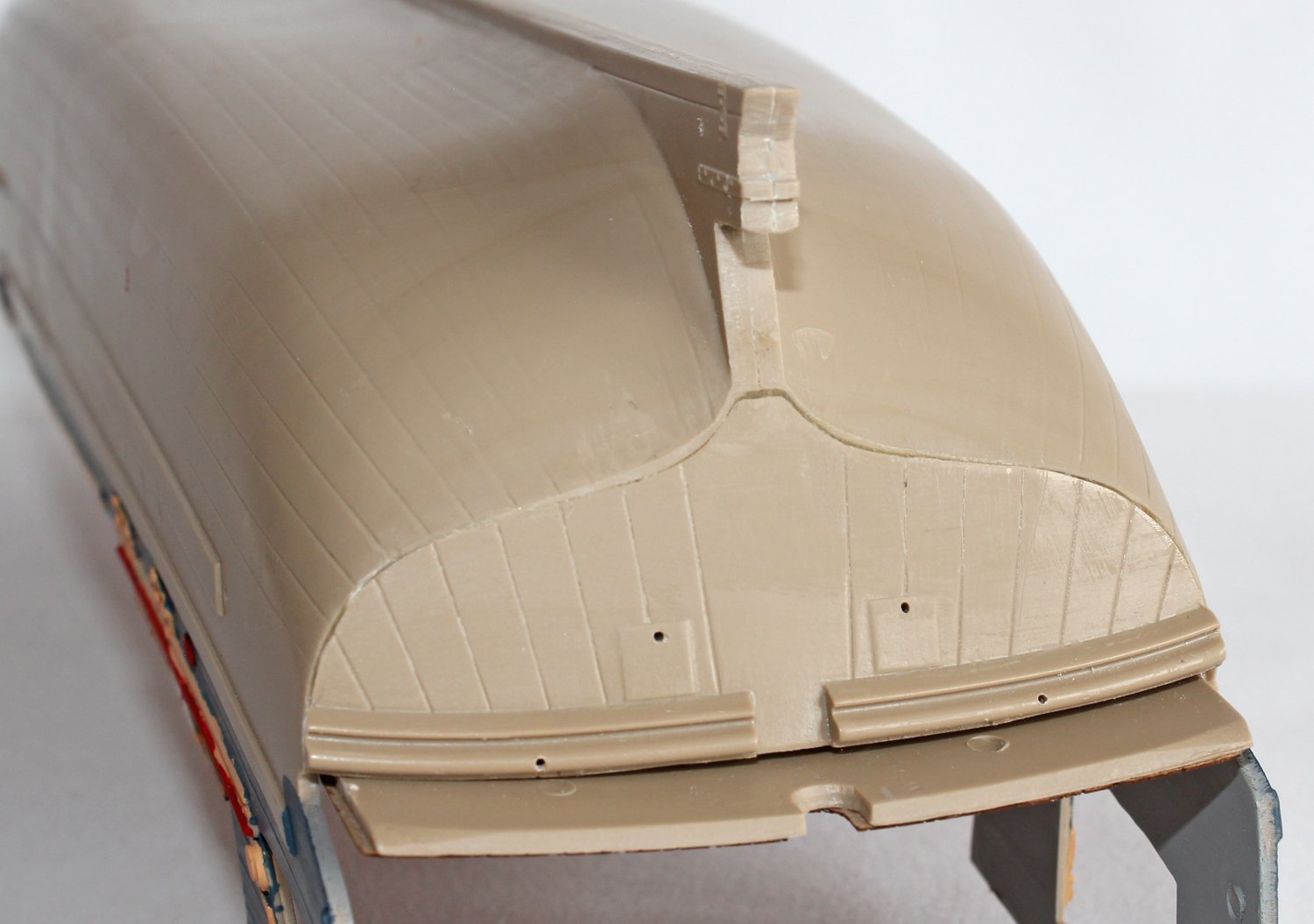
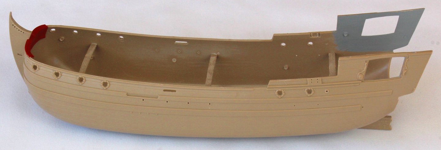
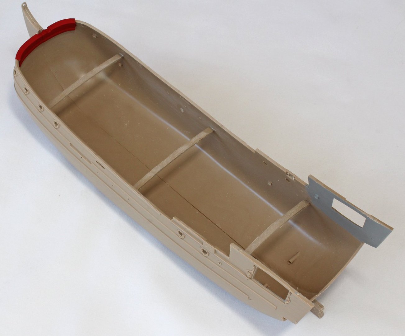
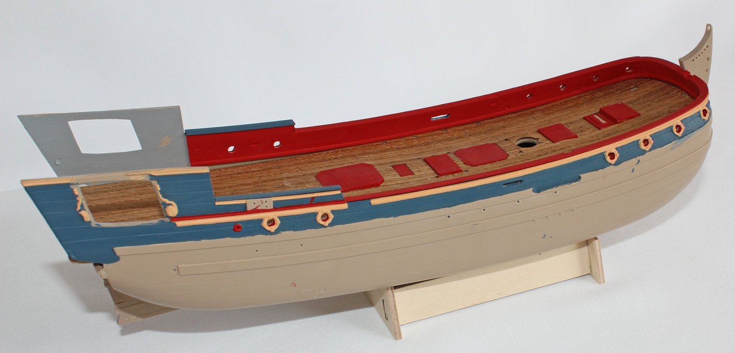
As mentioned in my previous post, the deck beams are not thought out well. They are very flimsy pieces of plastic less than 1/8” thick after sanding down for the wood veneer. There are tiny tabs on both sides of the beams which insert into notches in the hull. The idea is to flex the beams to insert them into the notches. When I attempted this, something very disconcerting occurred; the two hull halves separated. I sanded the joint line and glued the halves together again. The next day, the joint was still not solid. I took some scrap pieces of sprue, sanded them flat and tried to cement them together. I could break the joint. I then looked at the hatches and pillars. A tiny bit of pressure and the glue lines separated. I don’t know if it was the cement or the composition of the plastic that was causing the problem but from this point onwards, everything was glued with medium viscosity CA. The deck was installed next. It slides into the hull from the open aft end. There is no glue involved. The deck is theoretically held in place by the inner bulwarks. I was not comfortable with this concept and glued the deck to the aft deck beam after it had been slid into the hull. After the finish was applied, the diagonal striations in the deck became even more apparent. For someone building this model, I would suggest a hand-laid deck from thin veneer. Apply the planking to the deck before inserting the deck into the hull. The inner bulwarks were installed next. They were painted before installation and include a waterway molded into them. This is what holds the deck onto the beams. It is now time to start the outer hull painting. I apologize for the poor paint job. I had difficulty with the brush applications. Later on, I used an airbrush for the body of the hull and it became apparent that the paint was designed for airbrush application, not brush. Lesson to be learned is if one is dealing with an unfamiliar product, experiment using it in a place where it will not be seen (inside the hull before it is glued together, for example) before applying it to the outer hull. After the painting was completed the bulwarks were installed. The kit came with a laser engraved basswood base, as seen in the next picture. The slot for the keel is too wide and the outline of the base does not conform to the shape of the hull. I would suggest using the outer pieces but make new cross-pieces that fit the shape of the model. The lower transom is installed next. It was not a good fit and required a significant amount of sanding and filling.

- 14 replies
-
- 11
-
-
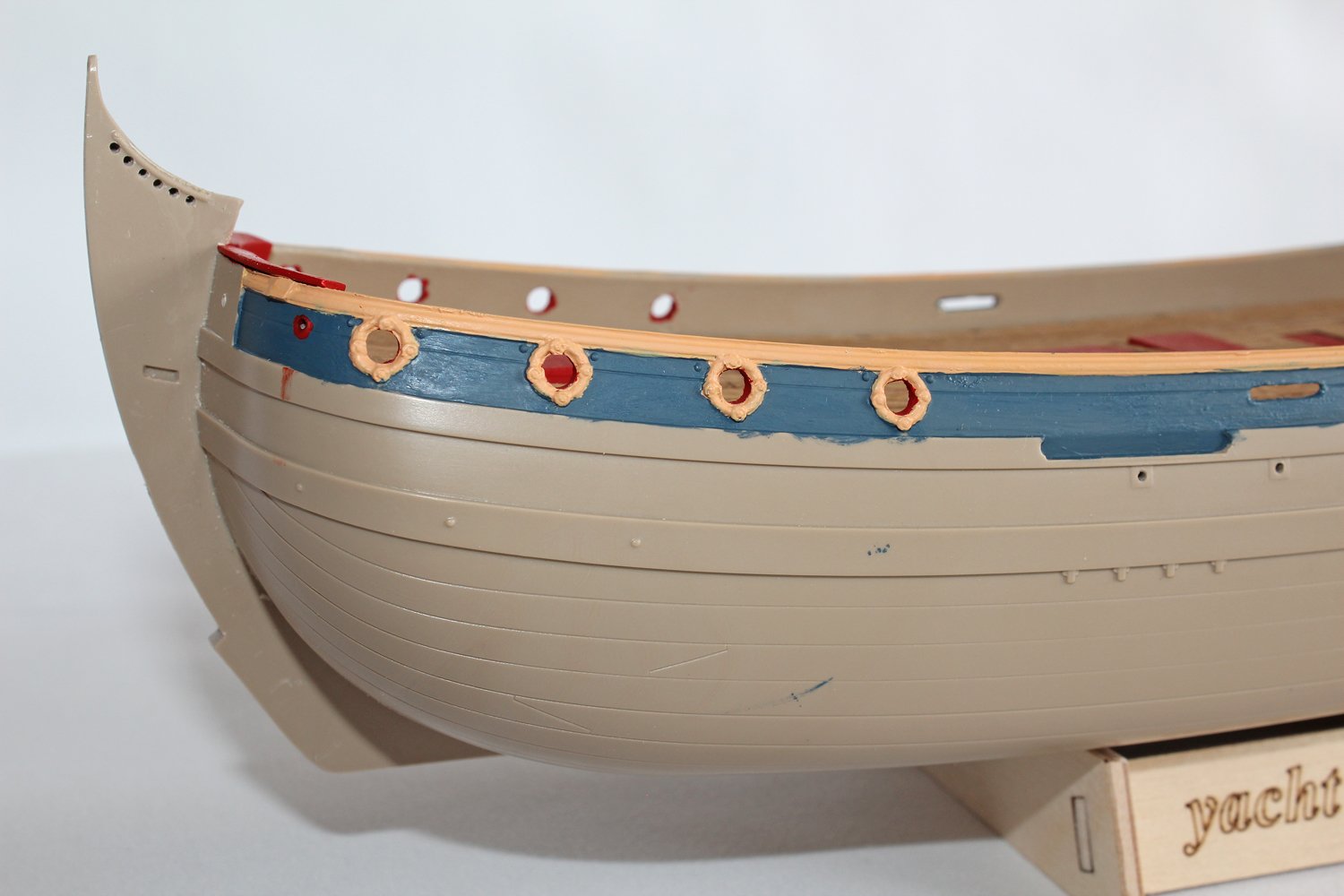
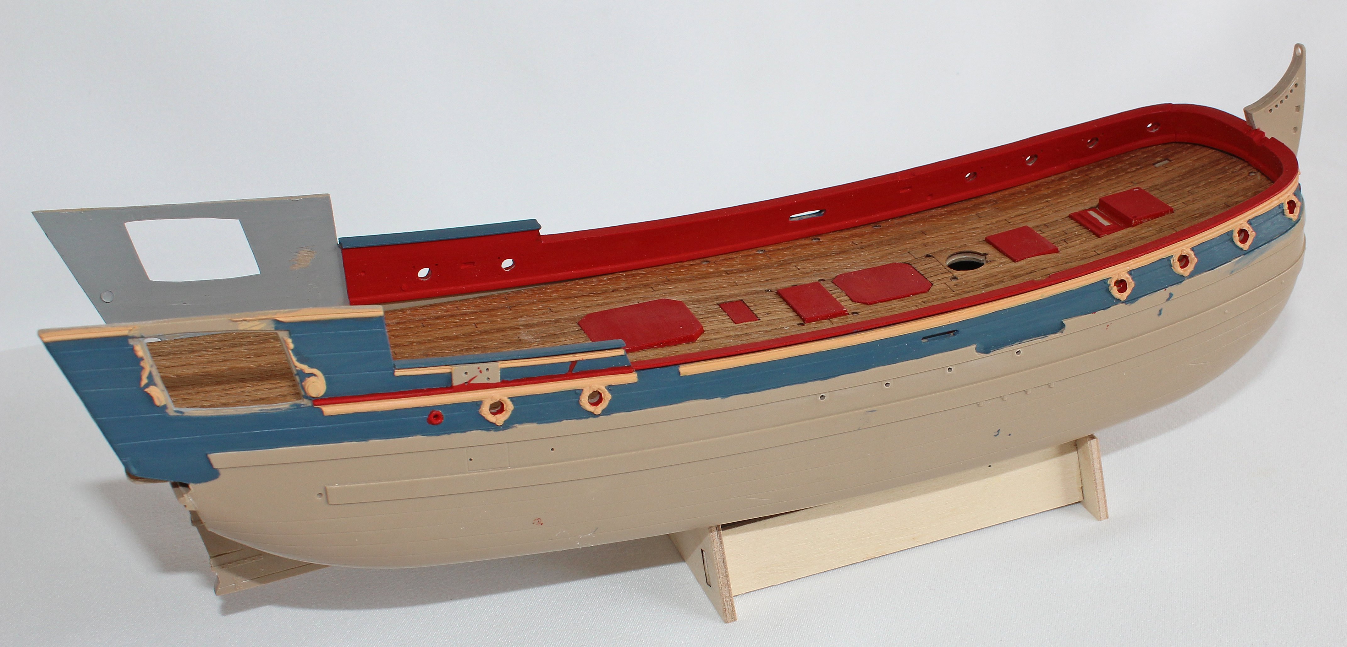
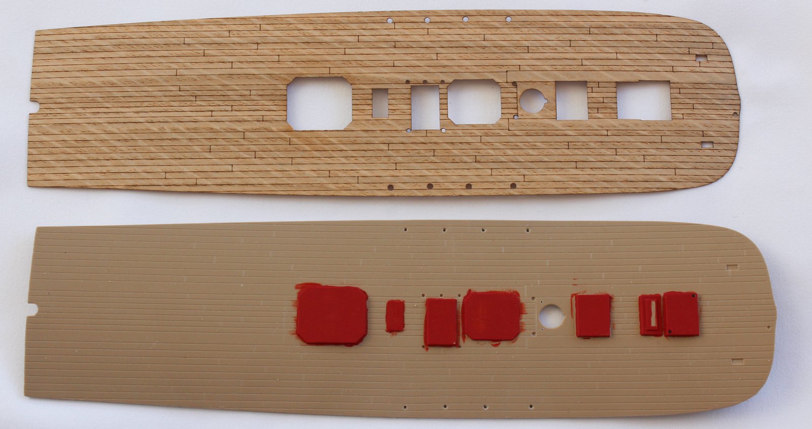
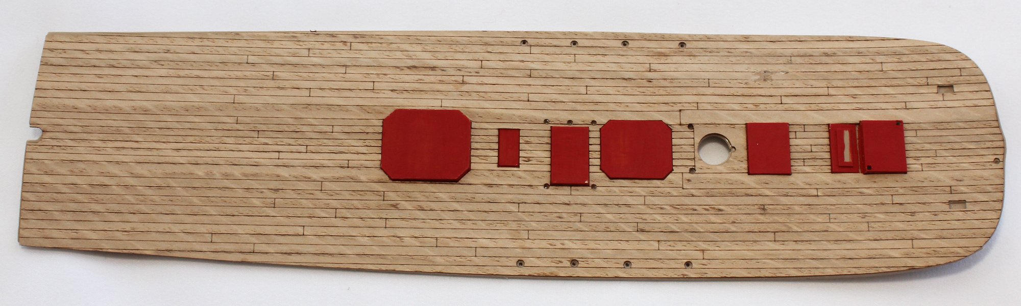
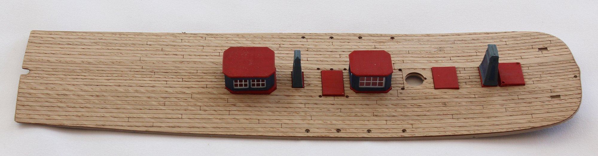
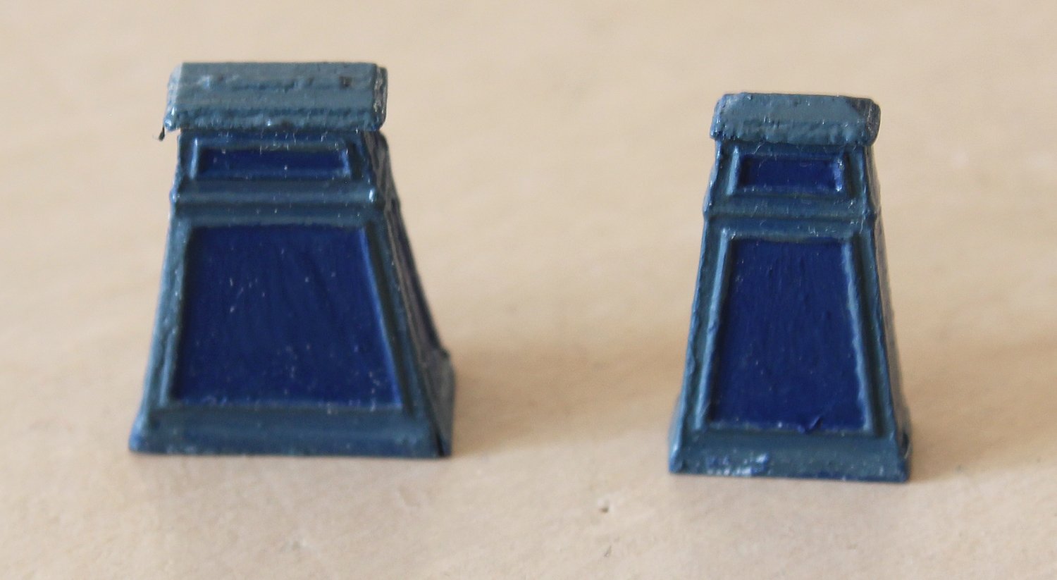
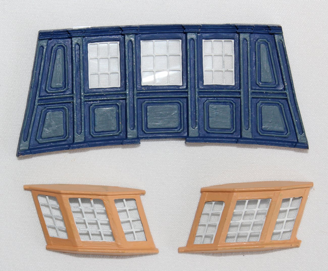
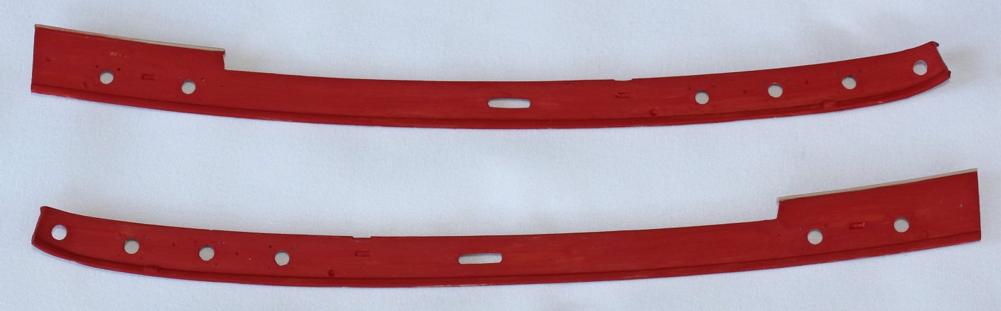
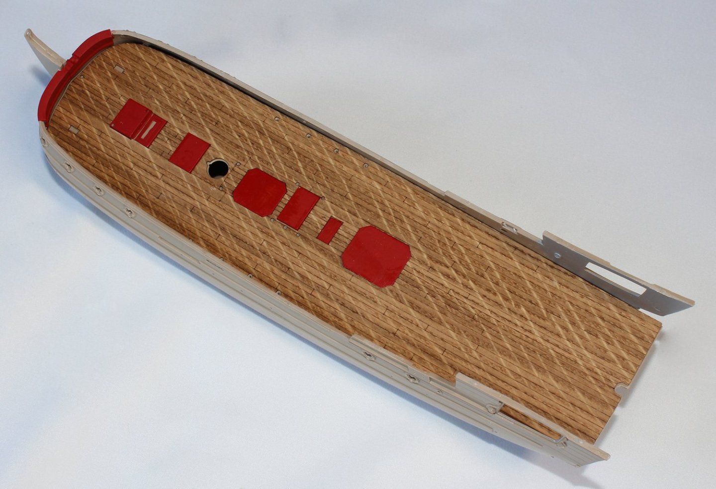
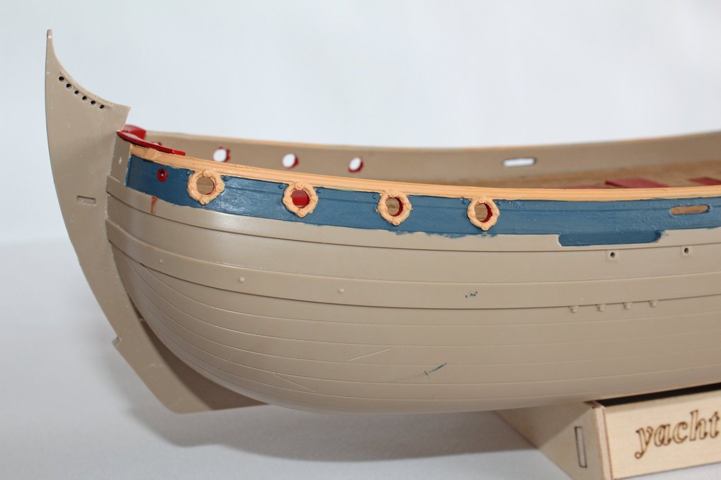
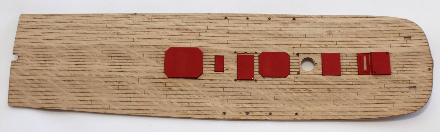
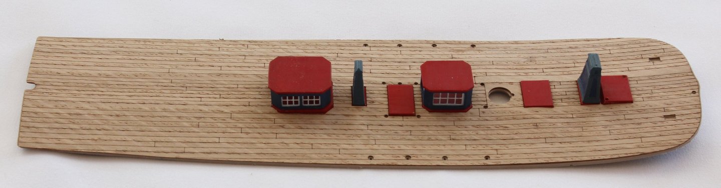
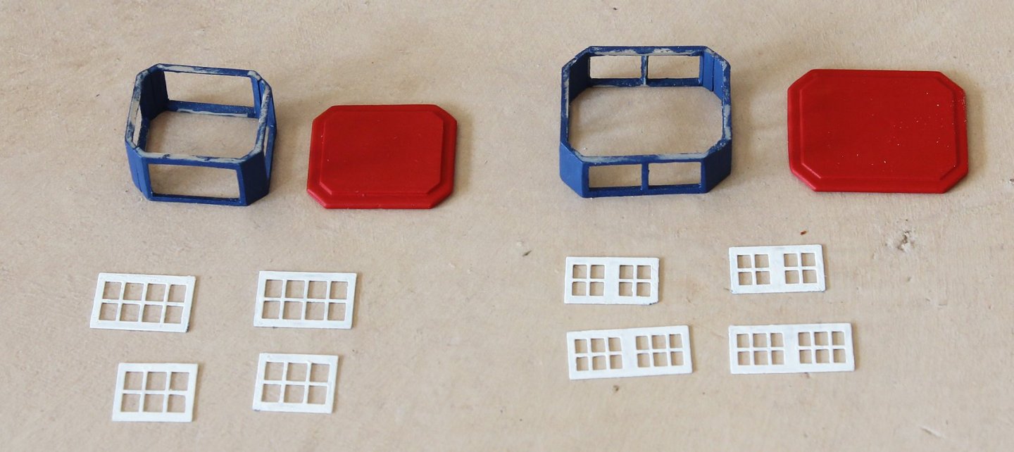
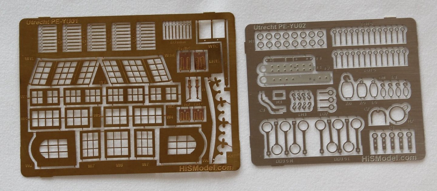
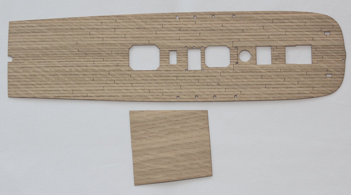
If you have not read my kit review, take a look at it before you begin. https://modelshipworld.com/topic/36826-utrecht-172-by-hismodel/ The first (and most important) step in any build is to read the instructions and understand what they are trying to say. Reading the instructions was easy…there is very little written. It is essentially all drawings and computer-generated graphics. Most of it made sense and I figured that the confusing areas would make themselves obvious further into the build. I have not built a plastic kit in many years. Construction sequences are different in a plastic model versus wood. They are certainly neater to build. No sawdust! I need to apologize ahead of time for some sloppy painting. My goal was to review the kit, not make this my magnum opus. Since everything gets painted prior to installation, I needed to buy paint and glue. I was told that many plastic modelers swear by Tamiya Extra Thin (the green label) and bought a bottle. There is a paint chart in the manual listing the names and numbers of four suppliers as well as the RAL equivalents. RAL is a system used in Europe for color standards. It started in 1927 and is administered by the German RAL Institute. I noticed a few problems. The RAL equivalents were different than some of the paint colors. Some of the item numbers did not exist. The yellow specified was bright yellow, whereas the replica ship’s yellow is more muted, closer to mustard. Even thought I am building OOTB, I could not stand the bright yellow and used Tamiya XF15, flesh, which closely approximates the replica. Since I knew I would be blending paint, I stayed with a single manufacturer, Tamiya. The first thing to be done is drill numerous holes for eventual insertion of ringbolts, cleats and belaying pins. Larger holes were drilled for the scuppers. The drill size is specified on the plans but in several cases, these are larger than necessary. I drilled all the holes initially with a #77 bit, enlarging them as required. Drilling plastic is much different from drilling wood. The bits do not like to bite and the holes need to be drilled by hand to prevent melting the plastic. After all the holes were drilled, the two hull halves were glued together. I do not know what the fit-tolerance is for plastic kits. There were several areas along the seam line that needed to be filled because of gaps. Part 3 of the instructions is called Components Assembly. It shows drawings of the various parts and their color. The nineteen pieces window glass are noted as part “TF”, transparent foil but this was not provided in the kit. I decided to use Saran Wrap. I started by assembling and painting the two hatches and two pillars, even though they would not be installed for while. The construction was straight forward. There are a lot of things in this kit which were well thought out. Other things…not so much. One example of this is the deck. This is the Premium version, which comes with a wood veneer to place over the plastic deck. This increases the thickness of the deck, requiring the deck beams to be thinned by the thickness of the veneer. The deck beams already are thin and bendable. Decreasing their thickness made them even more flexible. For anyone building this kit, I recommend either strengthening the plastic beams or replacing them with wood. Here, the mounting pads for the hatches and pillars have been painted red. The veneer has been glued onto the plastic deck. Because they are dissimilar materials, I used CA. My plan was to apply Watco’s Danish Wood Oil so any bleed-through from the glue would go away. You can see the coarse grain of the wood in addition to the diagonal saw marks. I was afraid to sand the deck because the scribing for planks was very shallow. The deck structures have been placed onto the deck temporarily.


- 14 replies
-
- 12
-
-
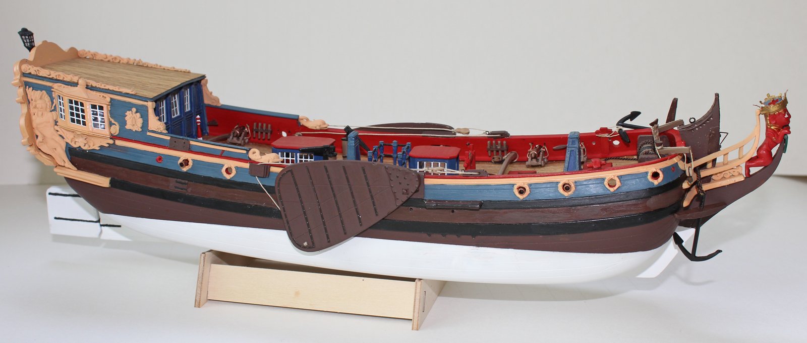
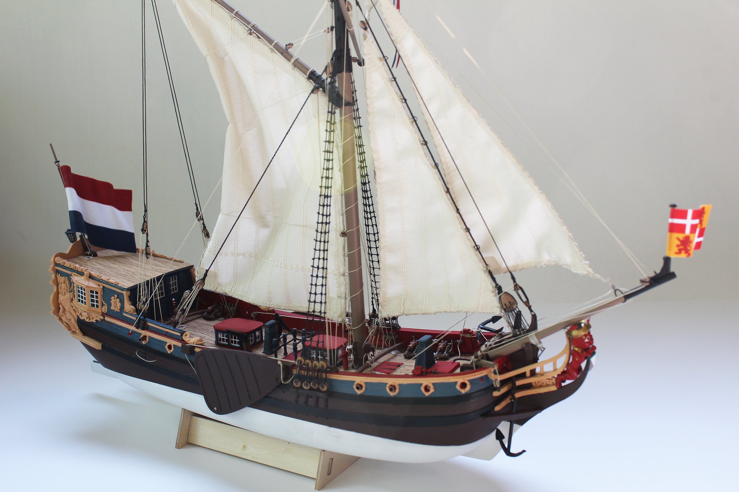
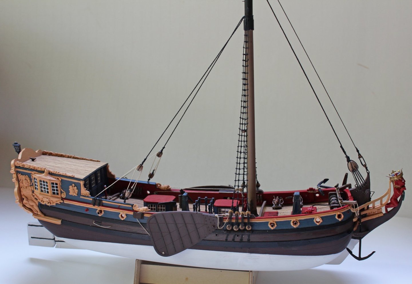
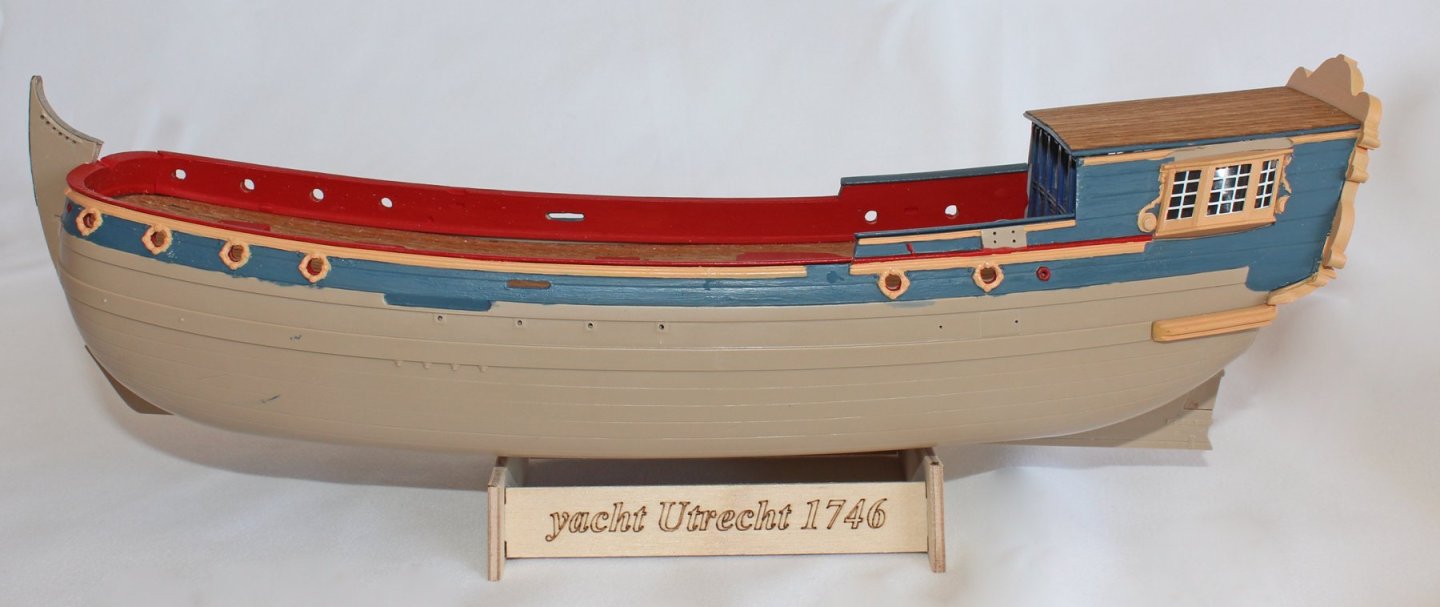
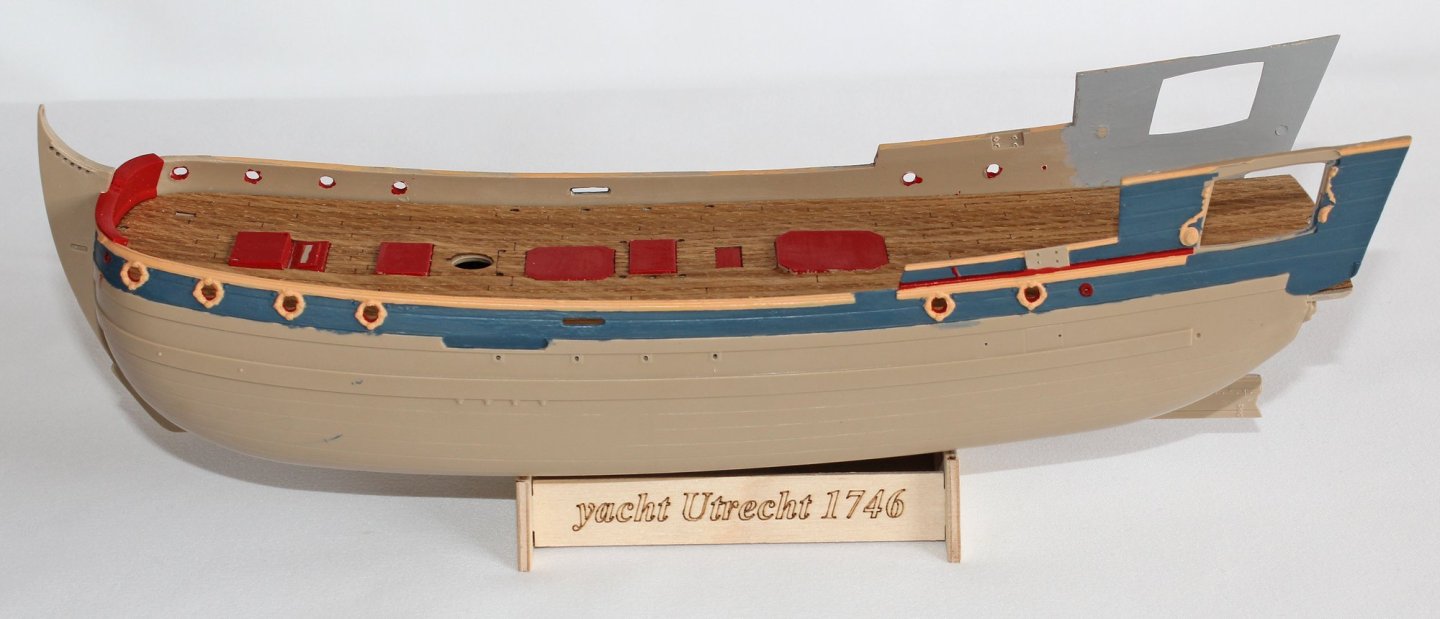
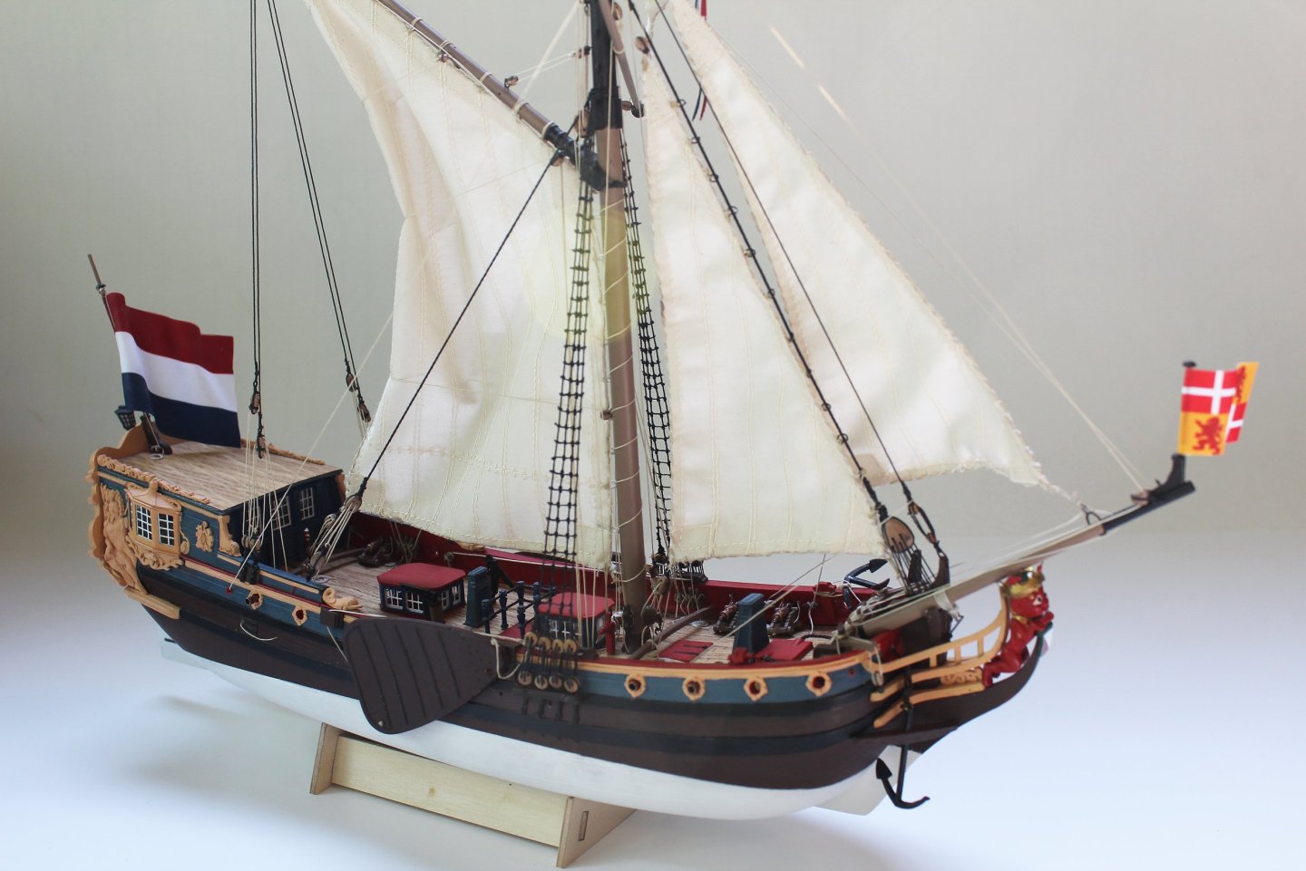
I hope to have the build log started shortly. Until then, this is the completed model.
- 14 replies
-
- 14
-
-
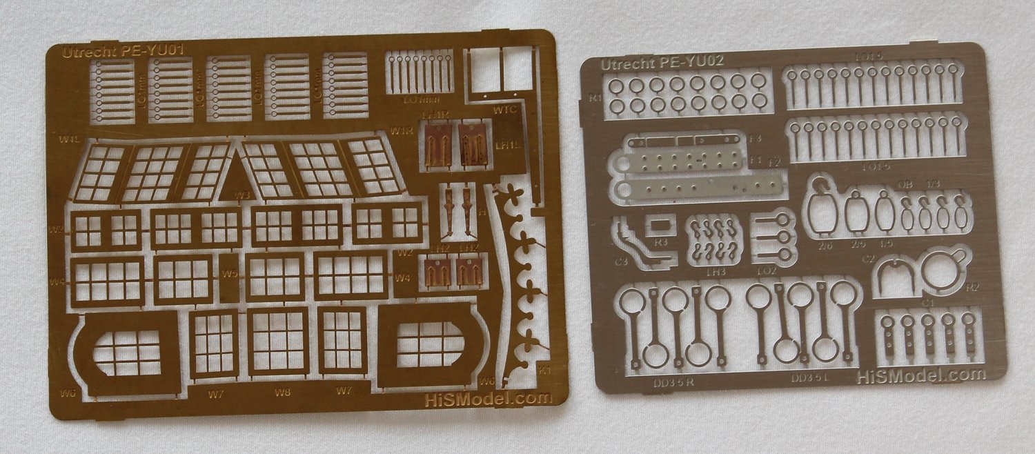
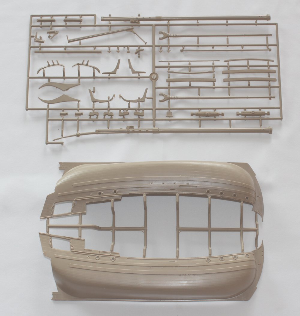
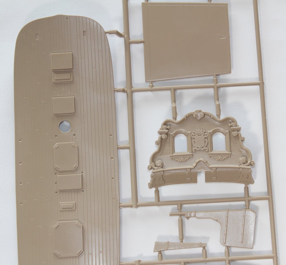
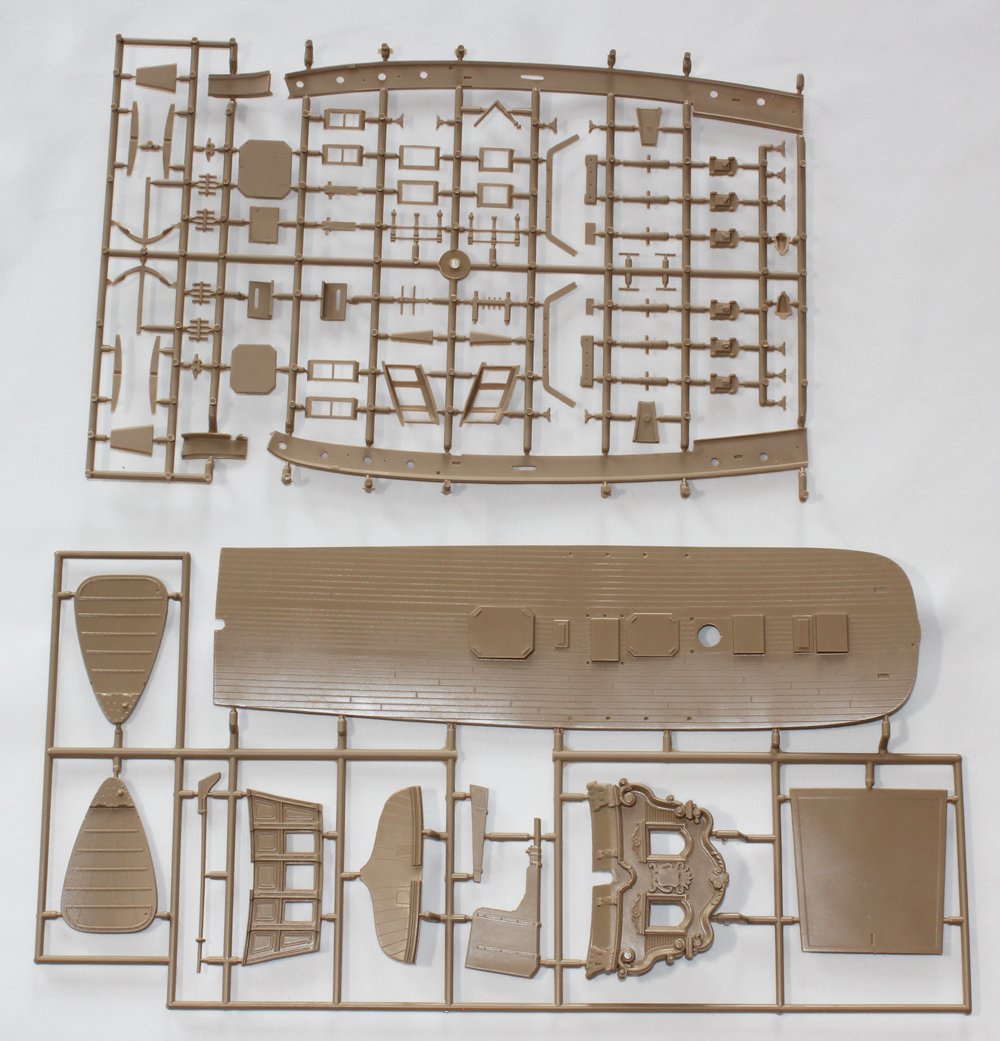
Our newest sponsor HiSModel is primarily a retailer of kits from several manufacturers. Their first in-house ship model kit is Yacht Utrecht 1746. Kurt was sent a copy of this kit for an open box review. The review can be seen in the latest issue of the Nautical Research Journal. I agreed to build the model from the perspective of a kit construction review. First, some background information. The Dutch yachts were built to transport important individuals to official meetings and ceremonies. They were typically heavily decorated. According to HiS, this model is based on the original plans by the designer Pieter van Zwijndregt. A replica was built between 1998 and 2003. It’s primary use now is as an event space. https://statenjacht.nl/ As with any kit review, the following are photos of what is included in the kit. Not shown are flags, twenty-six resin decorations and rigging components (line, deadeyes, blocks, etc.). Yes, this is a plastic kit! I have not built any type of plastic kit in over 15 years, and that was an airplane I built to learn how to use an airbrush (and promptly threw away). And my first and last plastic ship model was Revell’s Constitution back in the late 70”s. It is a little hard to tell from the pictures but there is a lot of detail molded into the parts. All of the decorative elements are crisp. Unfortunately, the port head timbers were molded incorrectly. As this is a kit construction review, I decided to build it completely out of the box, with no modifications to the components provided. The kit comes in two levels, basic and Premium. We were sent the Premium version. This has sewn sails, rather than a bolt of cloth, a wood deck, metal cannon in addition to the plastic ones, a few extra flags and a legal-sized poster of the boat. The decking is scribed for planking but the grain is very out of scale. The actual ship had a painted quarter deck but the kit included wood veneer without the planking scribes. The panel lines on the sails look good but the edge sewing is poorly done. The instruction manual is designed so that there is minimal need for written instructions. There are multiple construction drawings which show where to install various parts and where to drill different diameter holes. There is one page containing six pictures of the completed model; everything else is computer generated. Having already completed the model, I will give you my assessment before going on to the construction. This builds up into a nice-looking model. It is not without its problems, however. Some parts were not cast properly. The sails are of poor quality. There is insufficient rigging to complete the model. Some of the running rigging is shown as tarred line. The recommended paint colors do not match the replica ship. Finally, the instruction manual has a lot to be desired. I would not have known how to install the leeboards if I did not have Angarfarther’s build log to refer to. https://modelshipworld.com/topic/10401-statenjacht-utrecht-by-angarfather-136/#comment-311620 On the positive side, the resin castings are incredible. HiS should sell these separately for anyone else who wants to build Utrecht at 1:72 scale. The included blocks are the best commercial blocks I have seen. The line is fuzz-free. I cannot recommend this kit as something to be built out of the box. There are just too many small issues. I also do not recommend the Premium version. The coarse deck grain is distracting, the sails are of poor quality and the metal guns are not necessary. The plastic guns included are of very high quality and do not need replacing with metal. But for someone who would like to kit-bash this model, I strongly recommend the kit. It is not overly large (35 cm long and tall) and I was able to complete her in just over one hundred hours, including research. The condensed build log can be found under the kits build section.

-
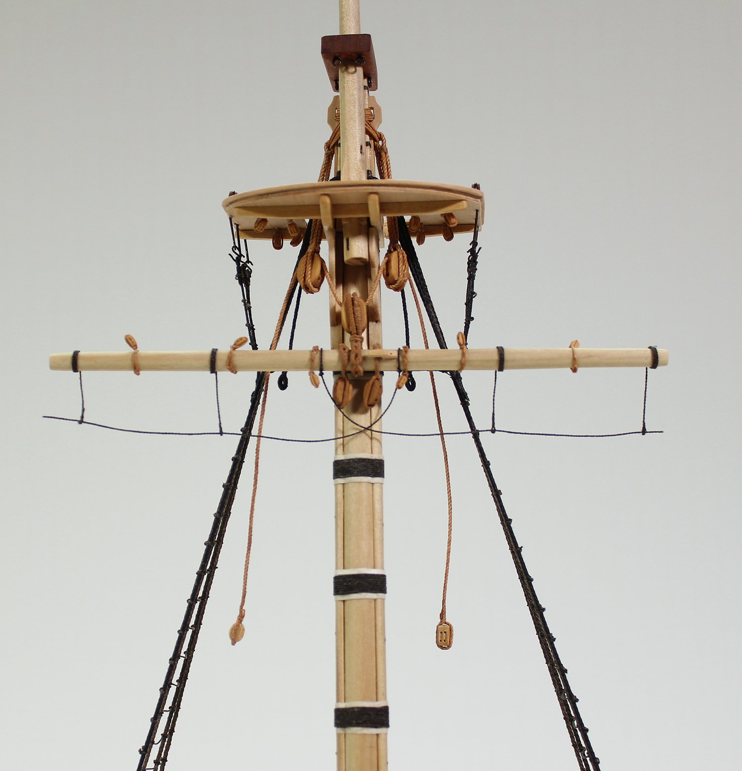
Stirrups are lengths of tarred line attached to the yard with an eye-splice at one end. The number and location vary based on the length of the yard. On this model, the stirrups are located between the two buntline blocks and at the end of the stub yard. The footropes (or horses) are also tarred and pass through the eye-splices in the stirrups. They are fixed to the yard near the opposite clueline block and at the end of the yard. The scale difference between the two ropes is slight enough that they were made from the same diameter line. The stirrups wrap around the yard three times and extend three feet below the yard. In practice, the free end of the stirrup would have been nailed to the back of the yard, but these were glued. They hang behind the yard. The picture shows the length of the stirrup relative to the yard. To install the stirrups I marked their locations on the yard and removed the buntline blocks. I made an eye splice on one end and wrapped the stirrup around the same diameter dowels three times. The wraps were coated with dilute glue. After they were dry I installed them and replaced the bunt blocks. The horses have an eye splice at one end just large enough to allow the line to pass through it, forming a loop. The loop is tightened down around the yard just outside the opposite side cleat. It then goes through the loops in the stirrups. It can be difficult to get the horses to have a pleasing curve. I shaped these by painting them with clear flat acrylic finish and letting it dry on plastic wrap. The horses were left free at the end of the yard as they would have continued further along the yard. The yard rigging is now finished.

- 80 replies
-
- 17
-
-
- rigging/masts
- NRG
- (and 2 more)
-
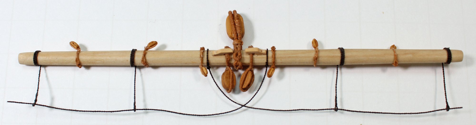
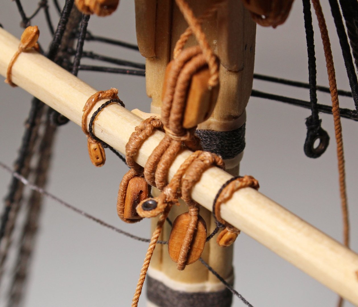
Cleats are located outside both quarter blocks. The length of the cleat is 125% the diameter of the yard. The easiest way to make two identical cleats is to glue two pieces of the correct width wood together with PVA. Shape them and then dissolve the bond in isopropanol. The cleats were glued to the yard outside the quarter blocks. There are three more blocks on each side of the yard: two buntline and one clueline. These are single blocks and are stropped just as was done with the quarter blocks except the strops are not served. I used 3 mm single blocks for them. Because these strops are not served, it was easier to make an eye-splice on each end to form the loops, just as was done for the futtock shrouds (minus the thimble). As with the other blocks, the strop seizing is on the fore side of the yard. The buntline blocks point skyward and the clueline blocks downward, as seen below. I have temporarily inserted the pin connecting the mast and yard. The pin passes between the turns of the double strop of the jeer block.


- 80 replies
-
- 23
-
-
-
- rigging/masts
- NRG
- (and 2 more)
-
Book on planking
tlevine replied to Fraser1945's topic in Building, Framing, Planking and plating a ships hull and deck
If you are referring to hull planking, consider the NRG hull planking model and look at the hull planking link under my signature. -
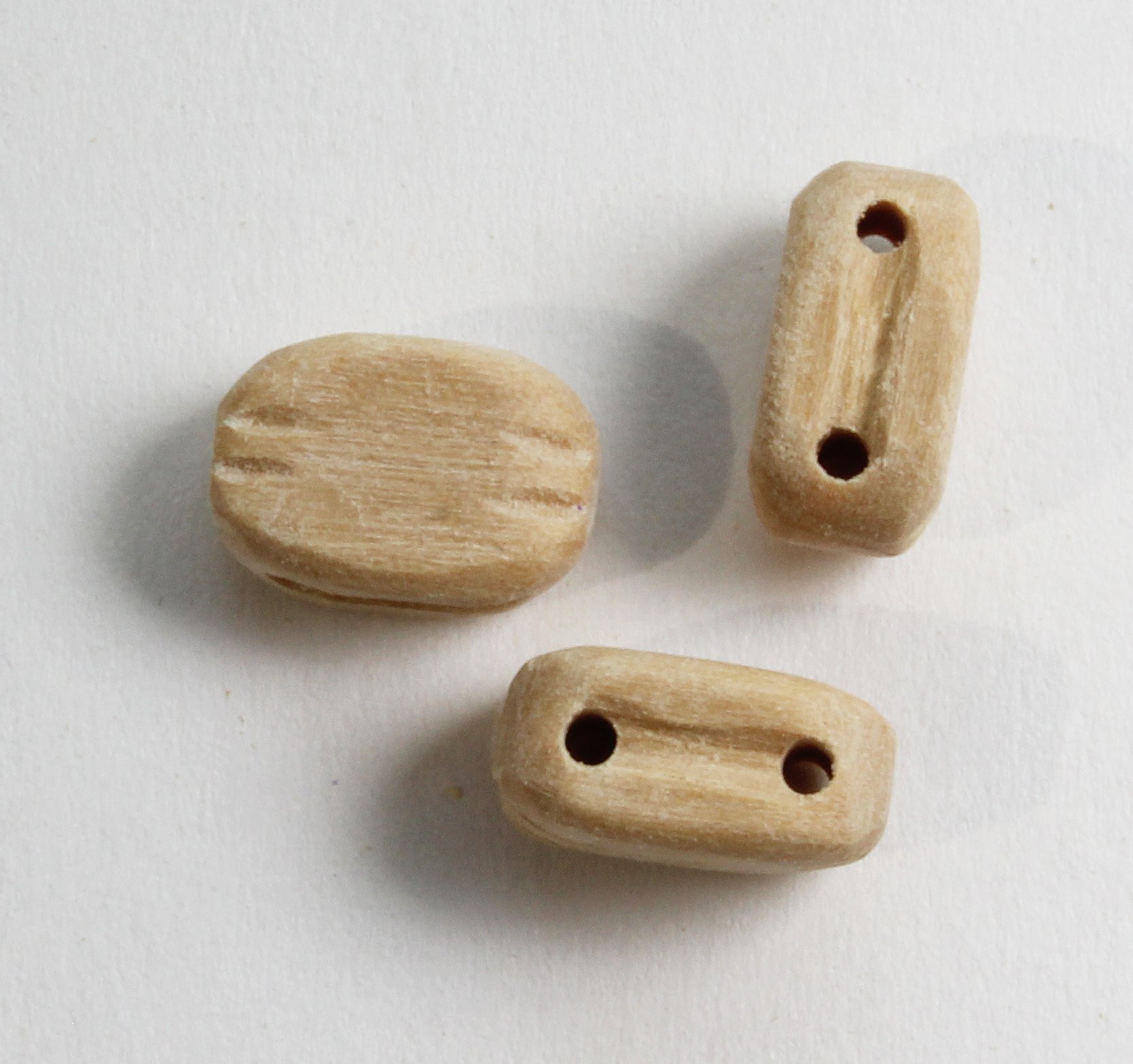
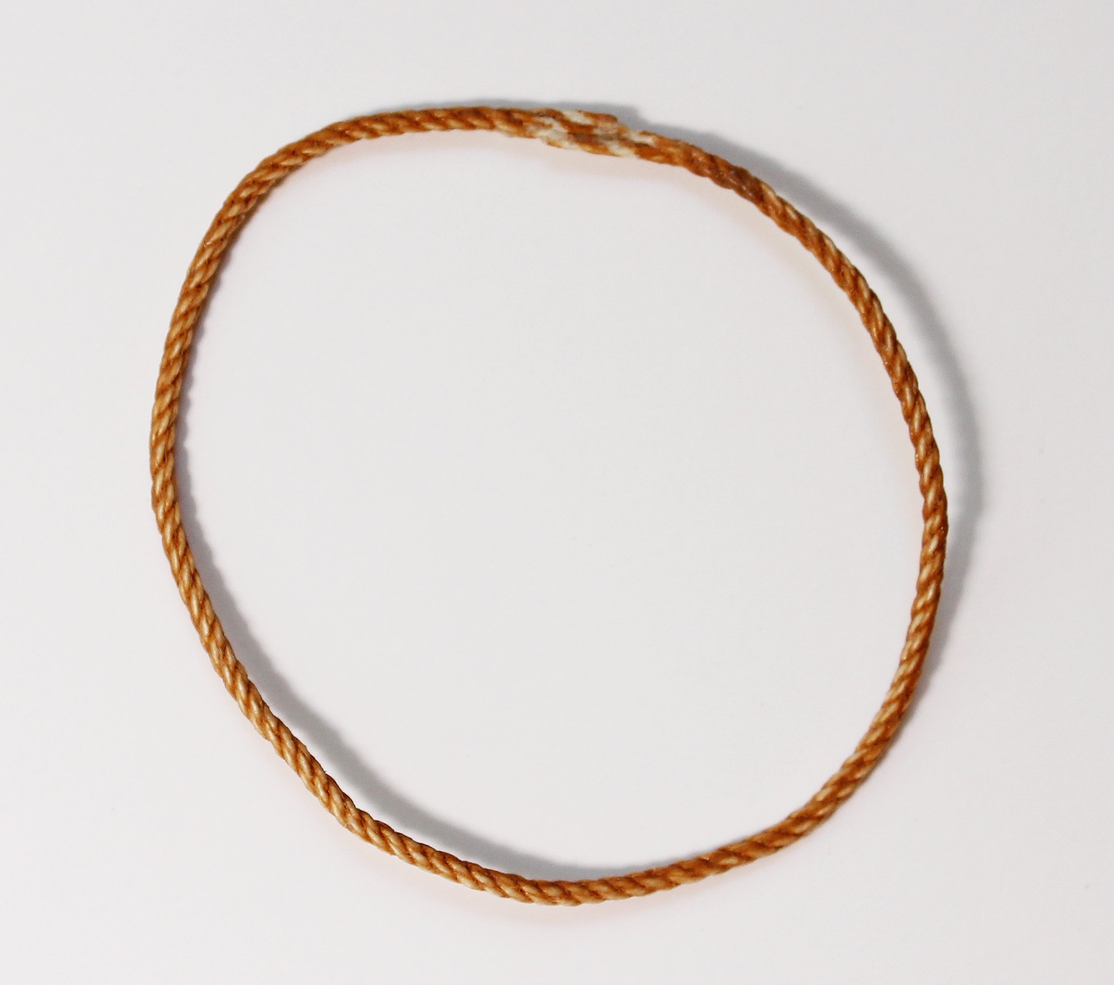
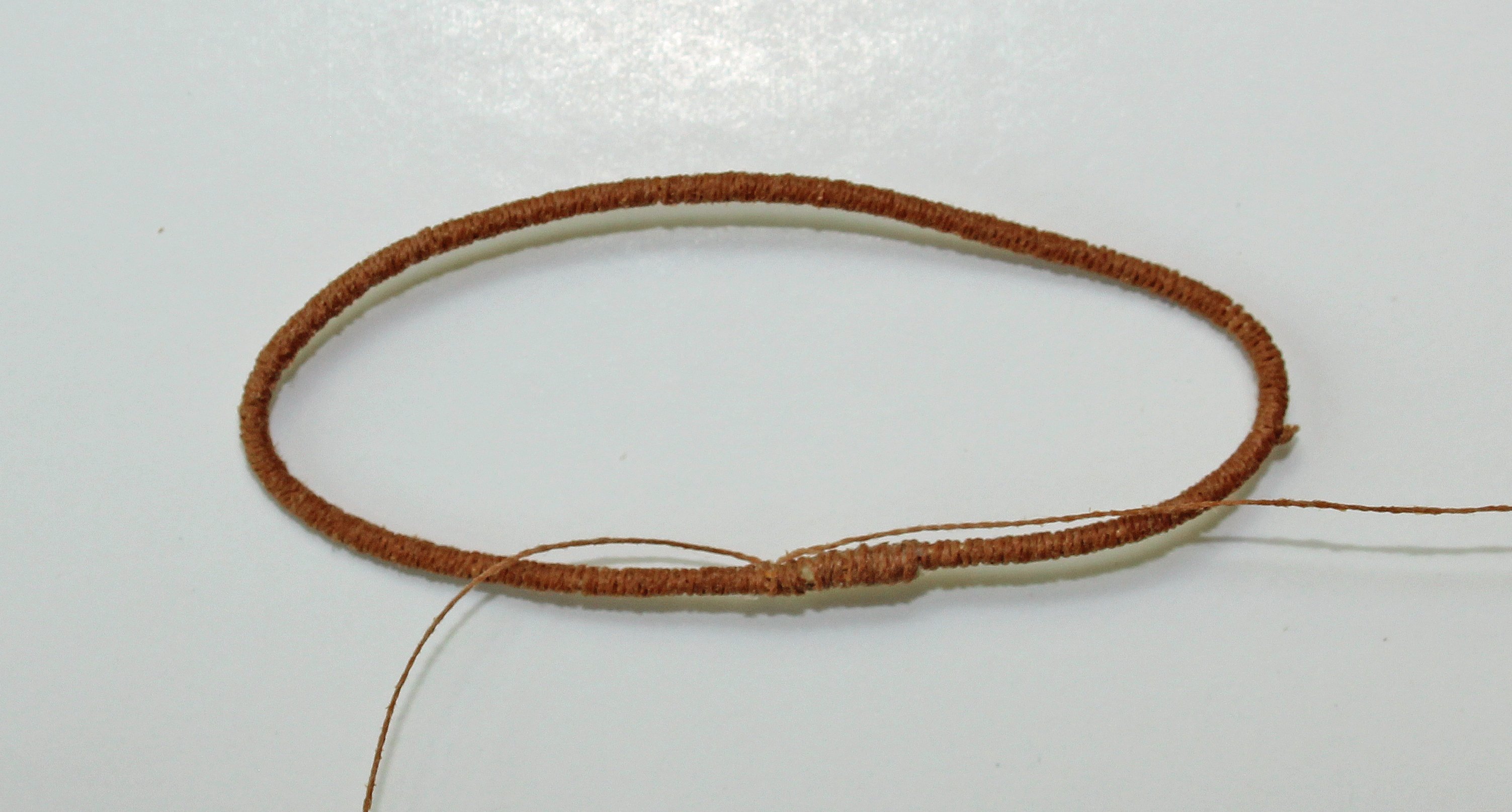
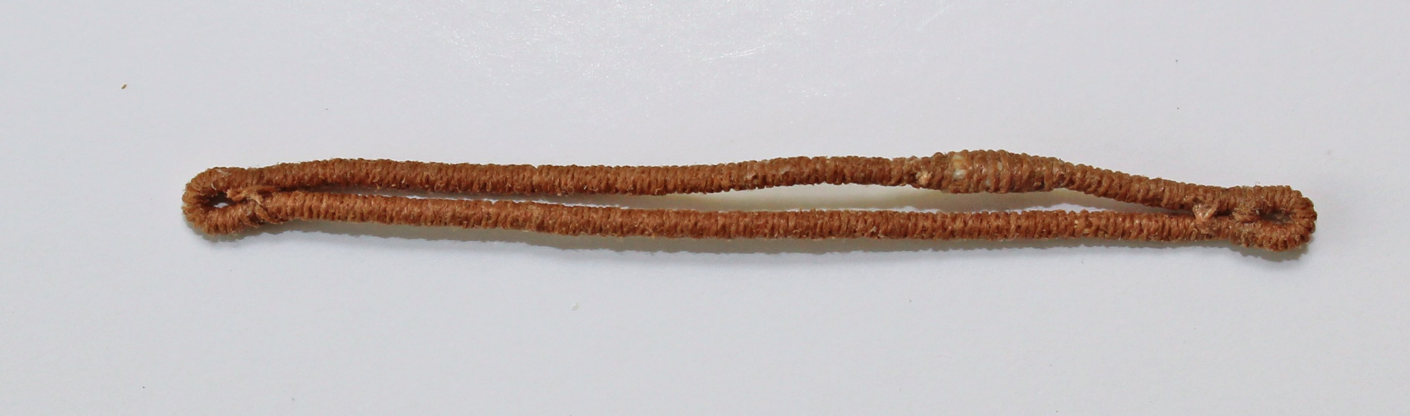
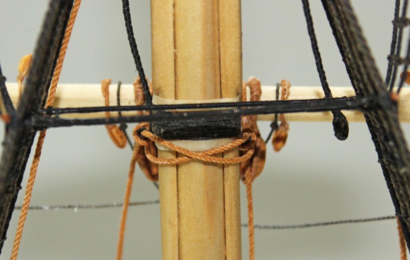
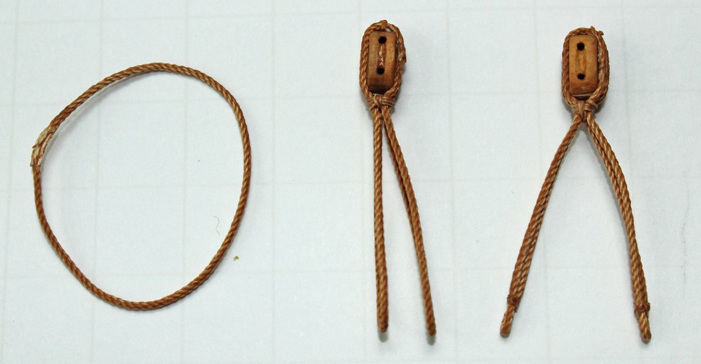
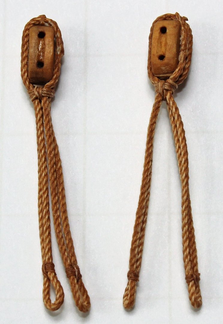
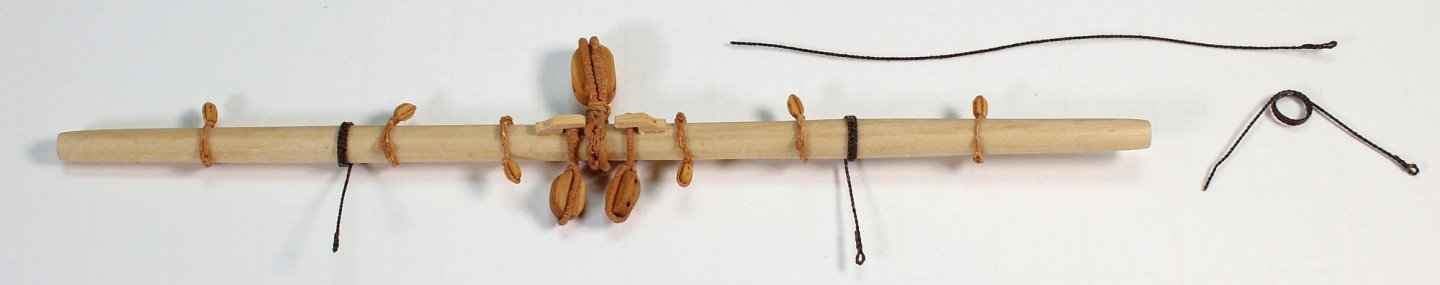
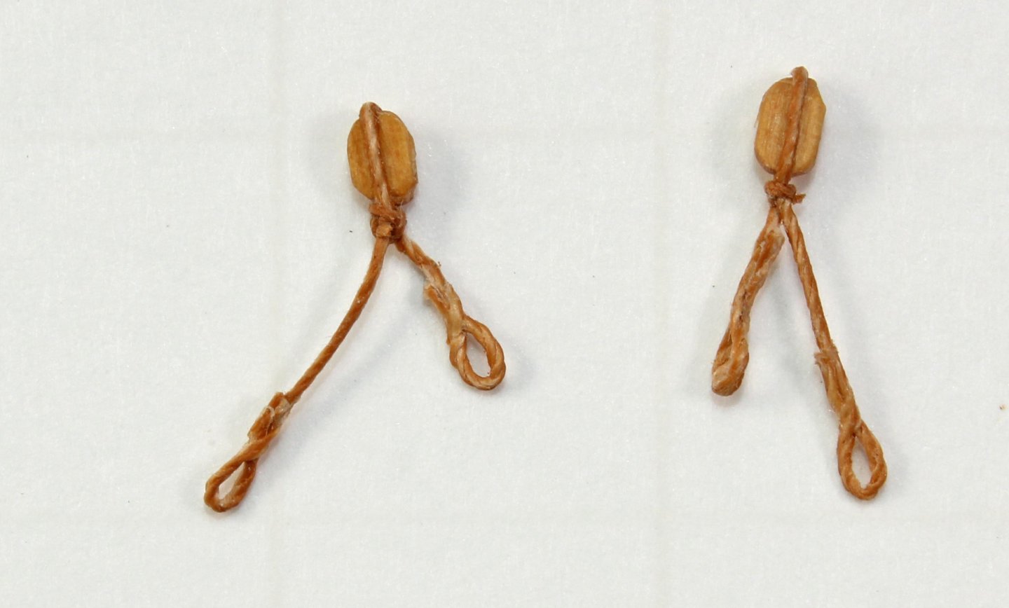
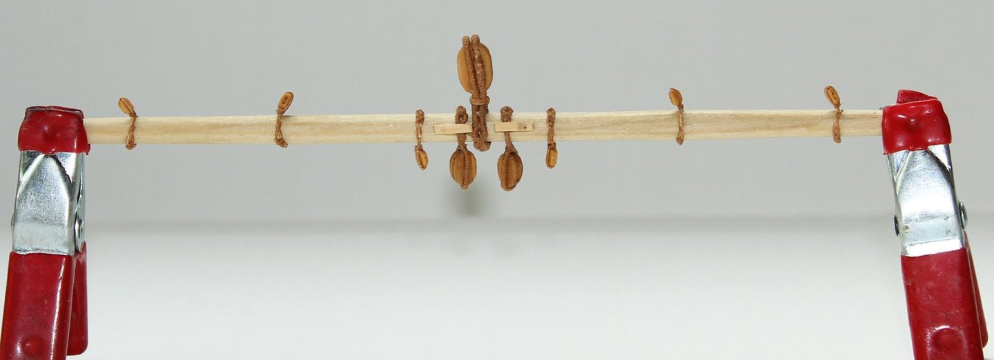
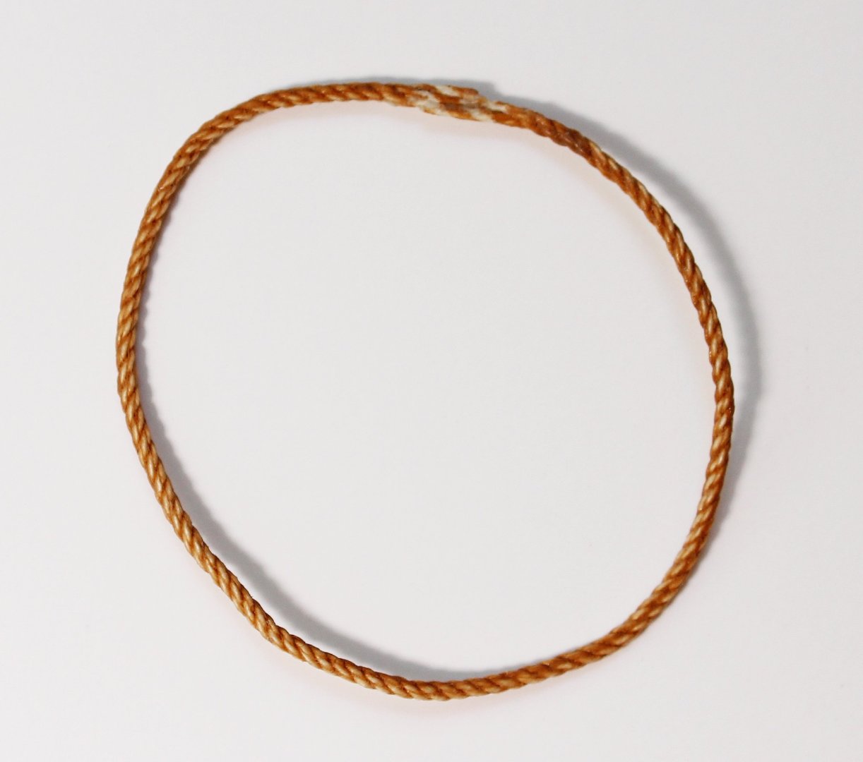
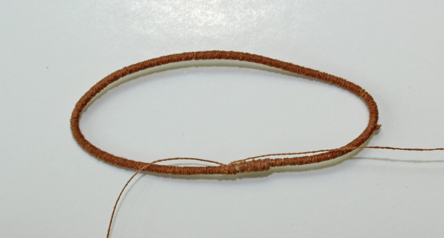
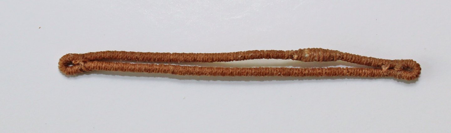
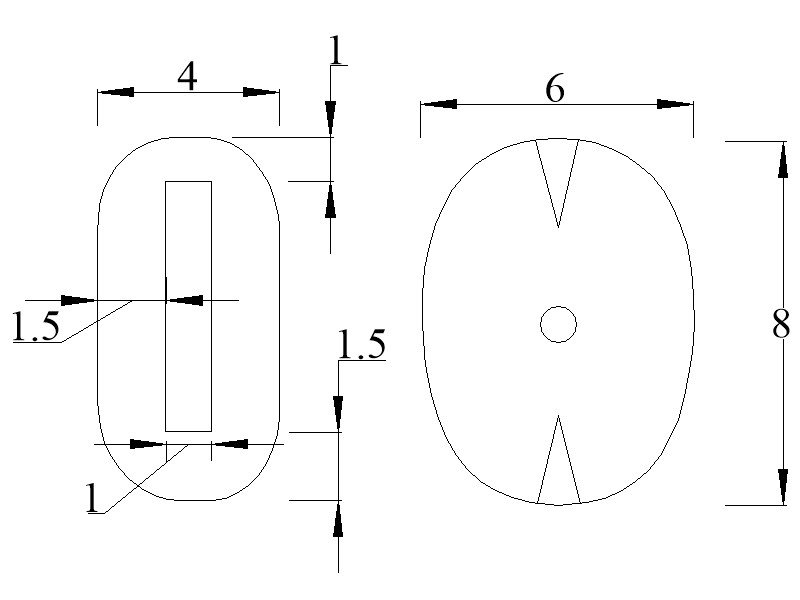
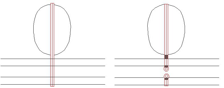
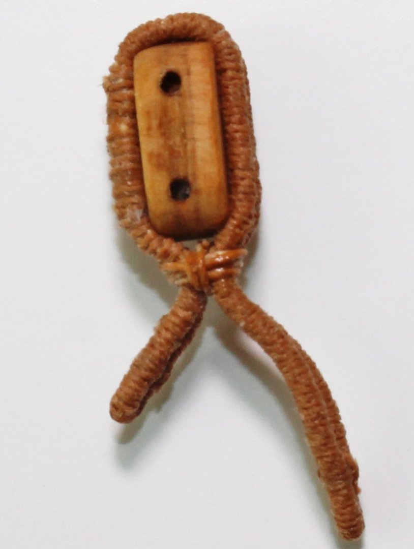
For anybody interested, the kit is now available through the NRG store. https://thenrgstore.org/collections/plans-and-projects/products/masting-and-rigging-kit The jeers are the pulley system used to raise and lower the lower yard. This ship has three jeer blocks, one attached to the lower yard and two others suspended by strops from the masthead. These blocks are not included in the kit. They are large enough that they are not difficult to make. The jeer tye runs through the blocks. The tye is a 6” rope with a scale diameter of 0.04”; the opening for the sheave is just large enough to allow the rope to run through it. Look at the block proportion drawing. The sheave opening width is “1” on the drawing. The length of the block is 8, the width is 4, and the breadth is 6. The sheave opening length is 5.5 times the sheave opening width. It is not centered in the block, as shown in the drawing. The jeer blocks have a double strop, so the blocks will need two grooves on their sides instead of just one. To make the three blocks, I took a piece of boxwood a little larger than required and sanded the sides to the correct width and breadth. Sanding instead of sawing prevented any burn marks on the wood. The tops and bottoms of the three blocks, the sheave opening and the strop grooves were drawn onto the wood. A space was left between the blocks to make shaping the bottom of the blocks easier. These blocks will have a false sheave and the sheave bolt is omitted because it is hidden by the strop. I started with the sheave opening. A 0.045” opening corresponds to a #57 drill bit. I drilled the holes for all three blocks at the same time. I used a drill press but this could be done with a pin vise. The key is to keep the drill bit exactly at 90 degrees to the wood strip. If you do not have a drill press, I would suggest drilling shallow holes from each side and having them meet in the middle. This is what happens if your angle is slightly off and you drill through from one side. A #11 blade was used to score the block along the pencil lines between the two holes and using a combination of files and #11 blade, the area between the score marks was shaped to simulate the sheave. Two shallow cuts were made all around both ends of the blocks and halfway between them. Using a V-shaped chisel, the strop grooves were cut. The halfway cuts acted as a stop to prevent from cutting into the next block. With a sanding stick, the upper part of the block was shaped on all four sides. I removed most of the wood between the saw cuts and start shaping the bottom of the block. Finally, the block was cut free from the strip and the lower edge was shaped. The jeer block is located in the center of the yard. The double strop for the jeer block is made from served 5” rope. Just like the quarter blocks, the jeer block is not centered on the strop, but at the 1/3 mark. The strop eyes are located on the fore side of the yard and secured with a seizing. I made a template for the strop from a scrap piece of rope following the instructions below. It took a few trials to get the correct length. Once I was satisfied, the strop splice was unglued and the total length required was measured. The pictures look somewhat crude but consider that the entire strop is less than 1.5” long. These pictures are enlarged so that you can see the process. I served a piece of rope, leaving extra unserved rope and serving thread for the splice. The two ends were untwisted to make the splice. This was glued and, when dry, served over with the extra serving thread. Eyes were formed at both ends of the strop. The block was positioned on the strop and seized so that one leg was twice as long as the other. The splice is on the side of the block, where it will be less noticeable. The arms were wrapped around the yard and the two loops were seized together. These pictures show both sides of the yard. The seizing is on the fore side.


- 80 replies
-
- 20
-
-
- rigging/masts
- NRG
- (and 2 more)