HOLIDAY DONATION DRIVE - SUPPORT MSW - DO YOUR PART TO KEEP THIS GREAT FORUM GOING! (Only 51 donations so far out of 49,000 members - C'mon guys!)
×

tlevine
-
Posts
2,033 -
Joined
-
Last visited
Content Type
Profiles
Forums
Gallery
Events
Everything posted by tlevine
-
 Don't worry about the frame tops at this point. They can always be levelled later, when there is no risk of damaging them. As I recall, I used a flat disc sander on my Dremel to bring them to their final height. Looking good.
 -
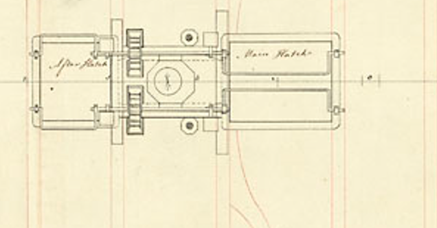
This is the same area from the Atalanta 1775 plan. Although it is a little hard to see on this screenshot, the mast partners only extend halfway across the beams.
-
As there is little camber, I took a 2" x 4" piece of 1/4" plywood and glued two different grits of sandpaper to it for fairing. That eliminates the round-over problem. Looking good.
-
I frame out the gunport before applying the hull planking. You can use a stick, cut to the correct dimensions, to act as a template to build the gunport around.
-
Recently, I have been taking jewelry-making courses. The sole purpose was to learn how to solder correctly. I previously used the same paste as you do, Greg, having had the same problem with solder shifting out of position. Now I use medium or hard silver sheet solder and flux almost exclusively. I discovered that my biggest problem was lack of patience. The metal need to be heated slowly and from a distance. This allows the flux to dry, holding the solder chips in place. At that point, "come in for the kill" and heat the piece just enough to allow the solder to flow.
-
La Palme by Tobias - 1:36 - POF
tlevine replied to Tobias's topic in - Build logs for subjects built 1501 - 1750
You will be the only one who notices! Looks great. -
Incredible is the only word I can use to describe it.
-
Kit Build Logs 1750-1800
-
Nicely done. When you build that next model, consider replacing the kit wood and spiling the hull planking.
-
To install the rail, I used regular spring clamps, with the jaws on either side of the hull planking. I placed a piece of scrap on top of the rail and pushed the clamps down so they dug into the scrap. As there is no tension on the rail, after a few minutes it is good to go.
-
Great reworking! I'm excited to see the new runs of planking.
-
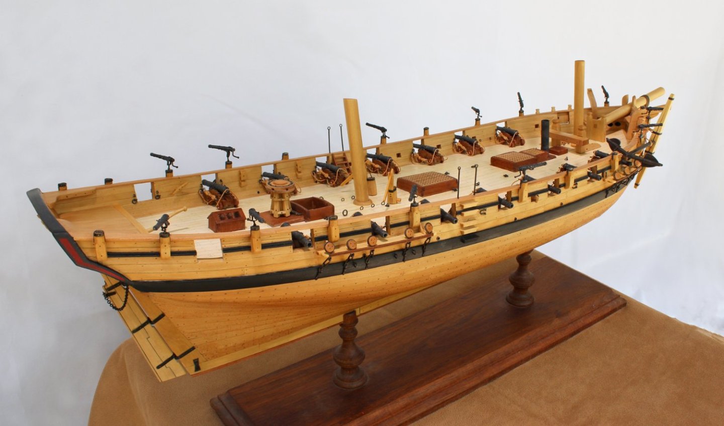
Thanks to everyone for your support. Greg, rigging her is not on the horizon. I already have three models that are incomplete because I abandoned their rigging. As to what's next, the base will take a bit of time. I have been considering Chapelle's Glad Tidings as a change of century. It only took the Smithsonian a year to send me the plans. Their excuse was that their copier was broken (and, no, I did not suggest Office Max).
-
Would you build a model of the model (which is what I seriously thought of doing) or a model of how she and her sister ship Drake were built?
-
Swallow is finished, other than a few touch-ups which will be addressed after I mount her. My plan is to duplicate the base from RMG as much as possible. It will probably take me a few weeks to source the wood and draw up the plans.

- 277 replies
-
- 33
-

-

-
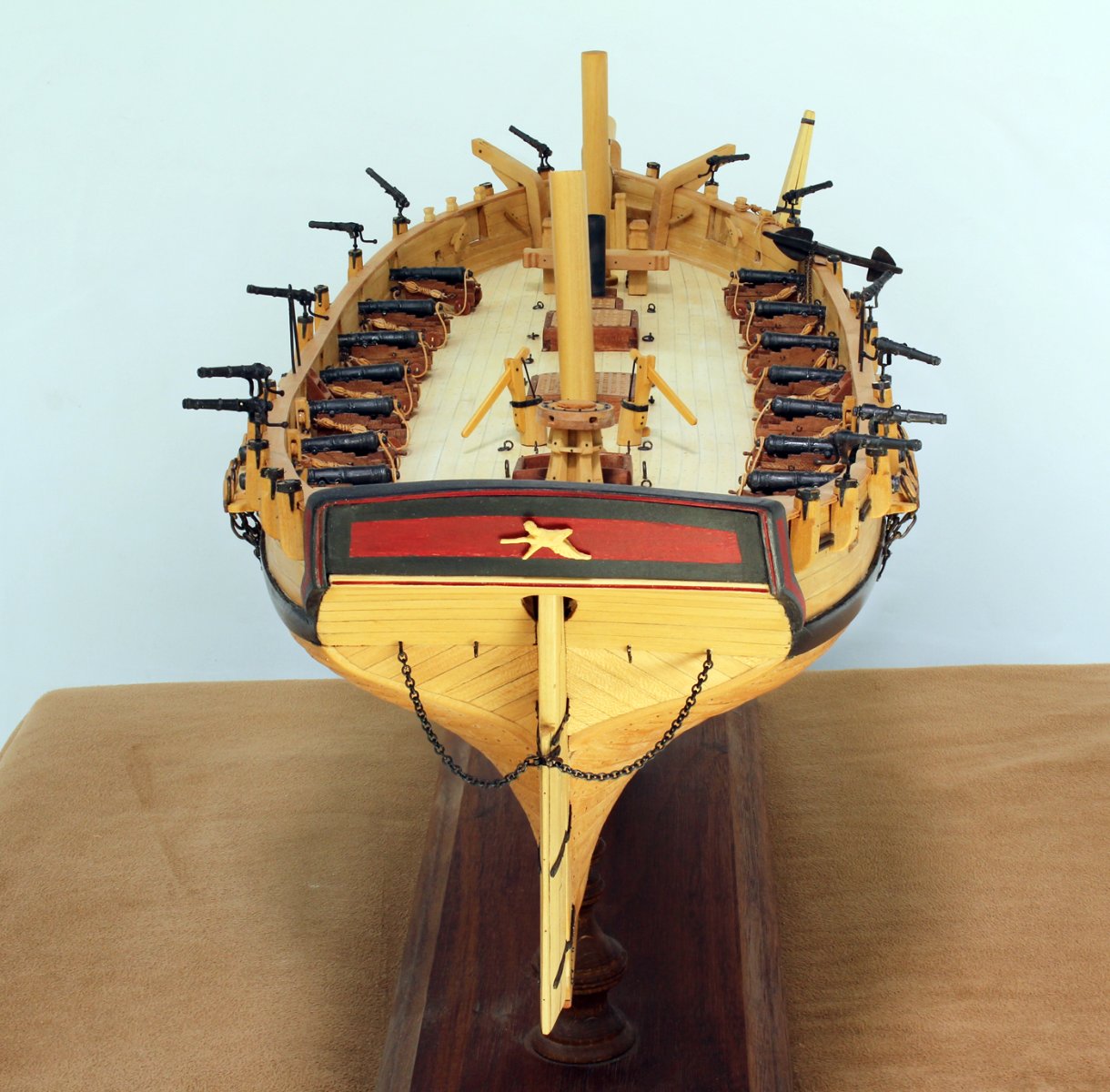
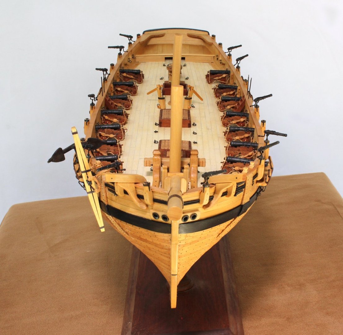
Swivel guns
tlevine replied to tlevine's topic in Discussion for a Ship's Deck Furniture, Guns, boats and other Fittings
I ran into the same problem, Allan. On my plans from the RMG, the tops of the swivel mounts are all the same distance from the top of the deck at the bulwark, 48". -
Based in information obtained in another thread (thanks to everyone for their input), I have decided to have the muzzle height at 4 feet from the deck. Leaving for the Admiralty Models workshop tomorrow morning so there will not be any updates for a week.
-
Swivel guns
tlevine replied to tlevine's topic in Discussion for a Ship's Deck Furniture, Guns, boats and other Fittings
Thank you everyone. I will locate the guns at chest height. The top of the mounts is at 3 feet above deck. Unfortunately, that will entail some serious surgery to the already-built mounts. -
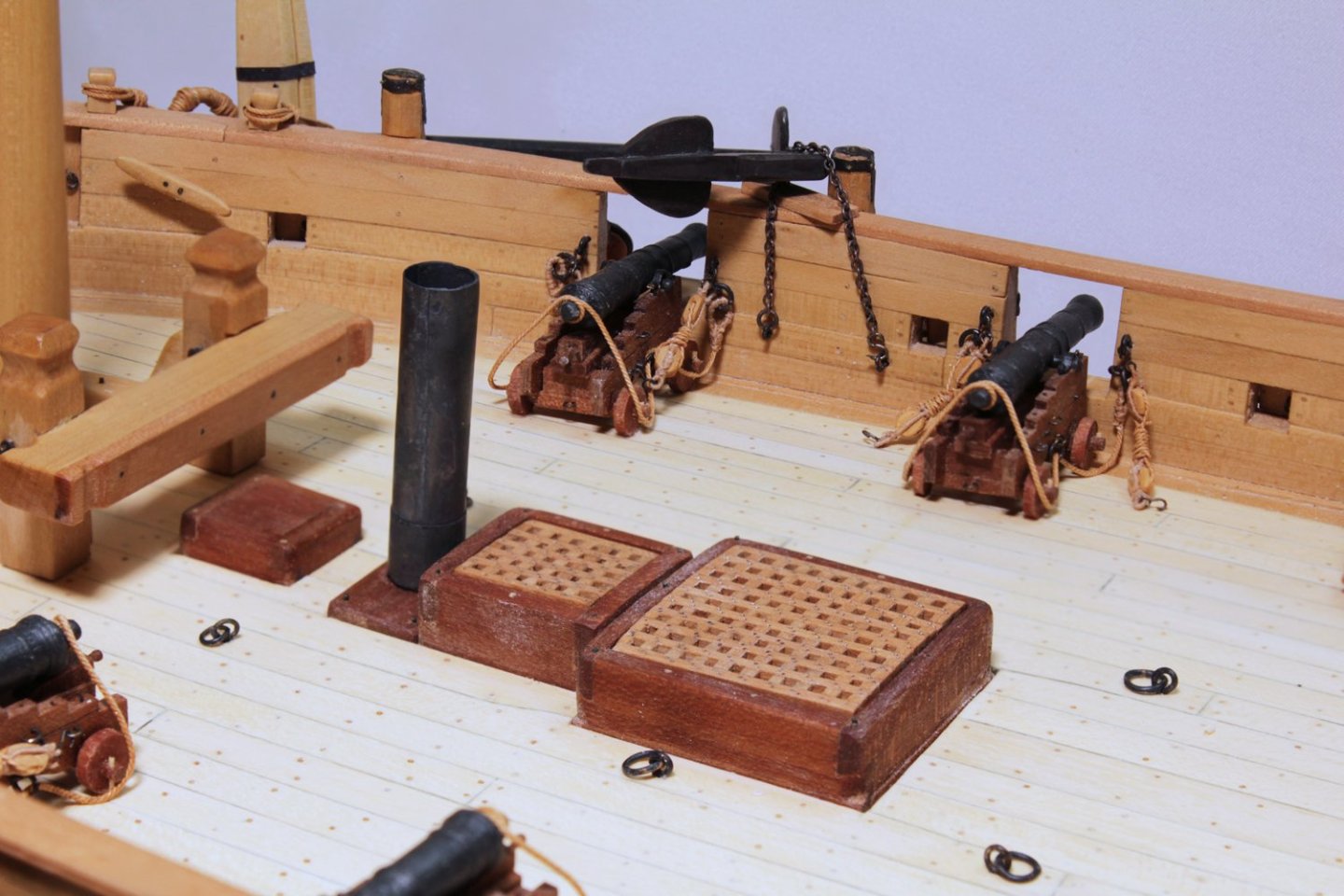
I am getting ready to install the swivel guns I made last year. They look too tall to be used comfortably. Does anyone know what elevation the muzzle should be from the deck when it is horizontal? I am guessing eye level but would hate to install them and then find out I guessed wrong.
-
Swivel guns
tlevine replied to tlevine's topic in Discussion for a Ship's Deck Furniture, Guns, boats and other Fittings
Thanks, gentlemen. Unfortunately, without knowing the height of the rails and swivel post, it is difficult to determine their elevation from photos. -
Swivel guns
tlevine replied to tlevine's topic in Discussion for a Ship's Deck Furniture, Guns, boats and other Fittings
Thanks, Louie. It would be the late 18th century, specifically for my Swallow build. I made them last fall and when I installed them yesterday, they just seem too high up from the deck (five feet). -
What would be the height for a swivel gun above the deck? Waist? Chest? Eye level?
-
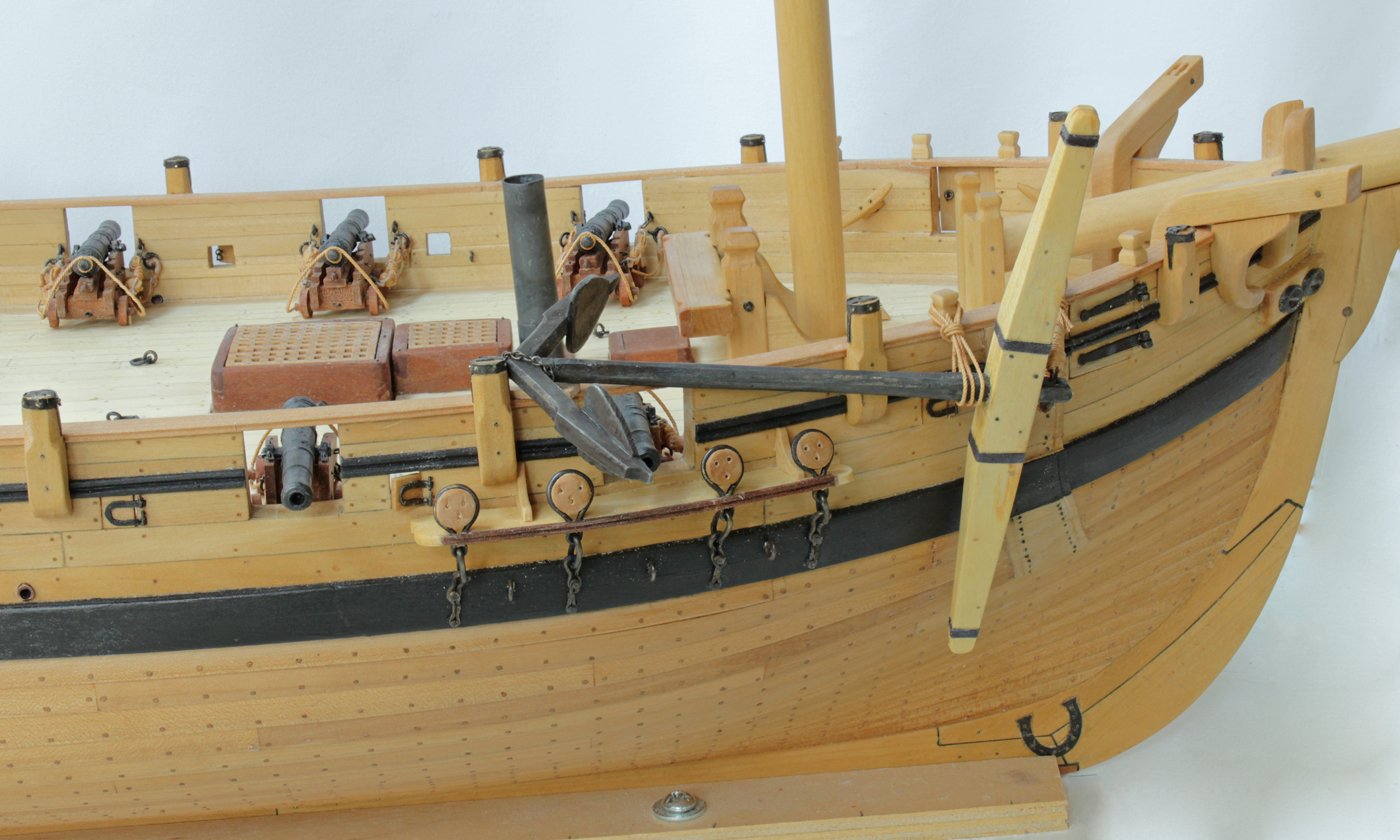
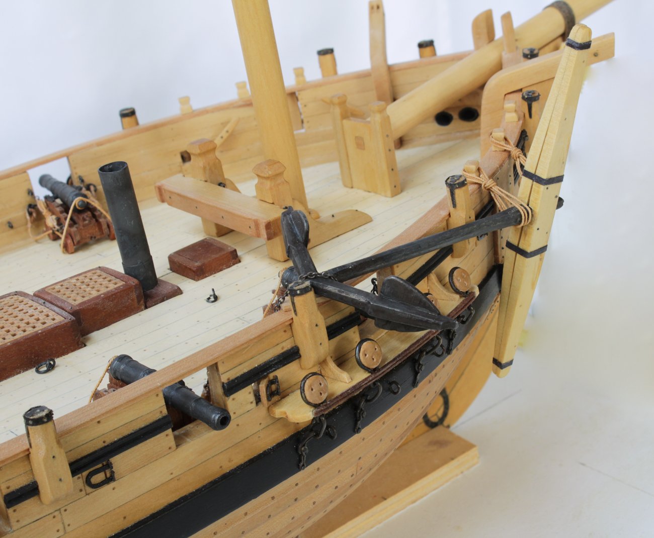
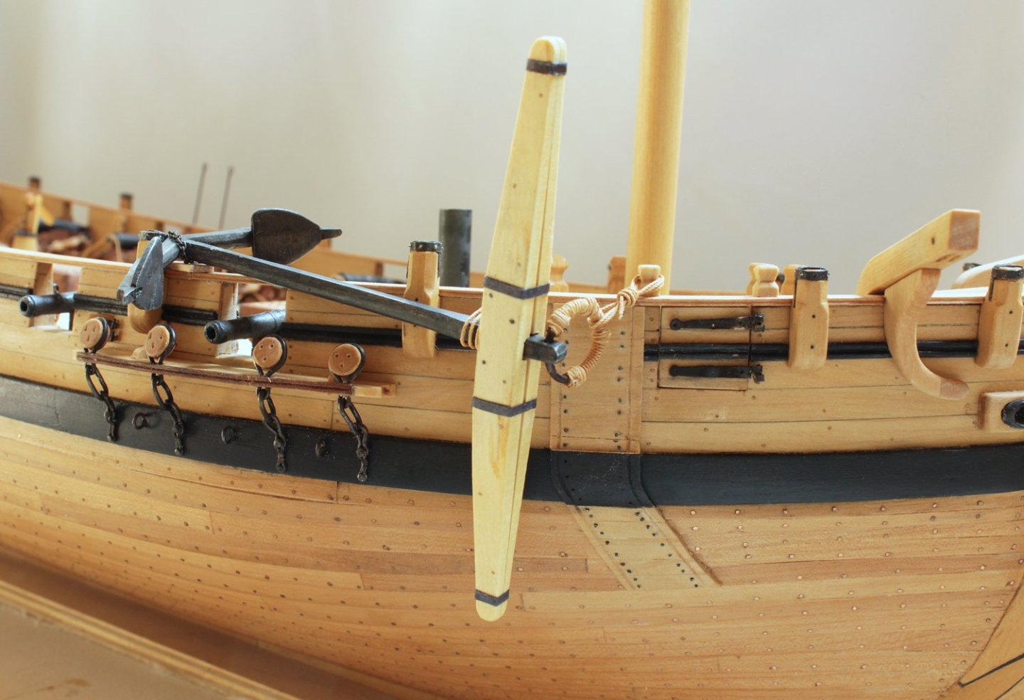
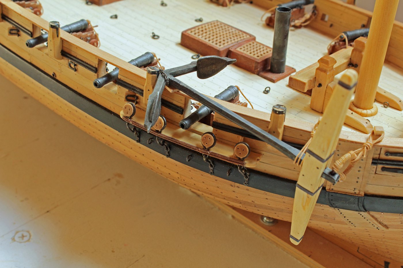
After looking at other models for ships this size, I decided to secure the lower shank with the shank painter. As druxey suggested, one end is attached to a ringbolt inside the bulwark and the free end terminates in a hook which is secured in a second ringbolt. The upper part of the shaft and the ring were tied off to timberheads. I have added a block of wood on the rail under the anchor to protect the rail from damage.
- 277 replies
-
- 23
-
-