tlevine
-
Posts
2,033 -
Joined
-
Last visited
Content Type
Profiles
Forums
Gallery
Events
Everything posted by tlevine
-
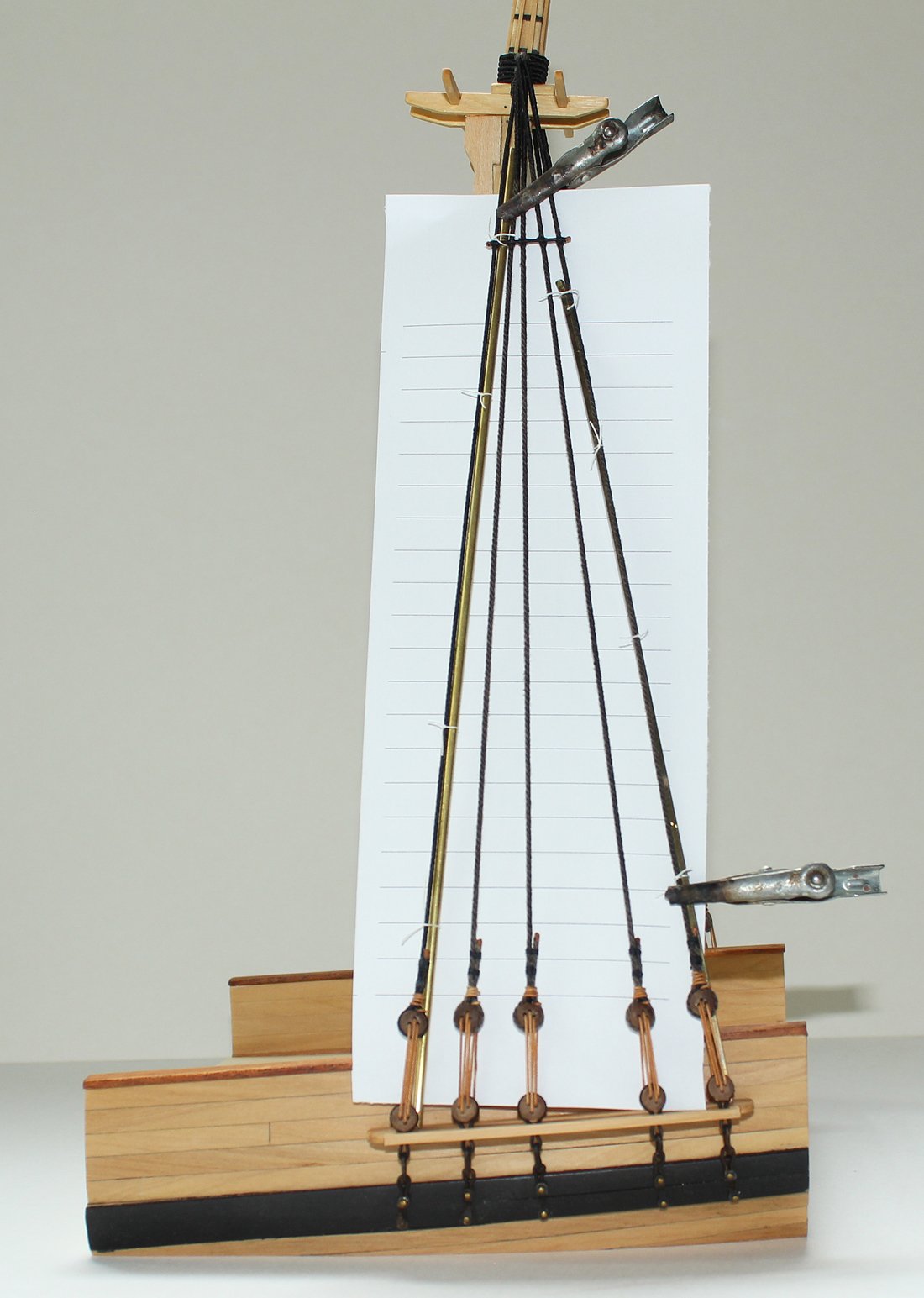
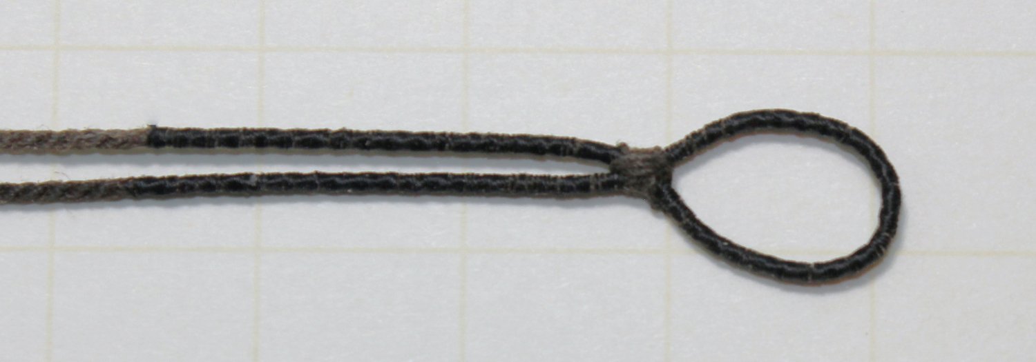
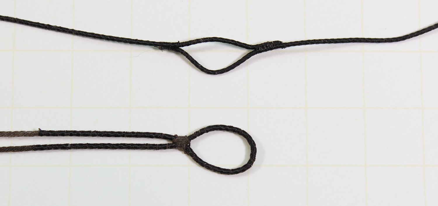
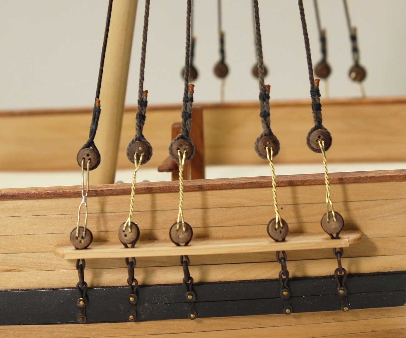
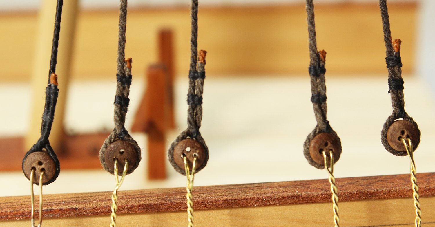
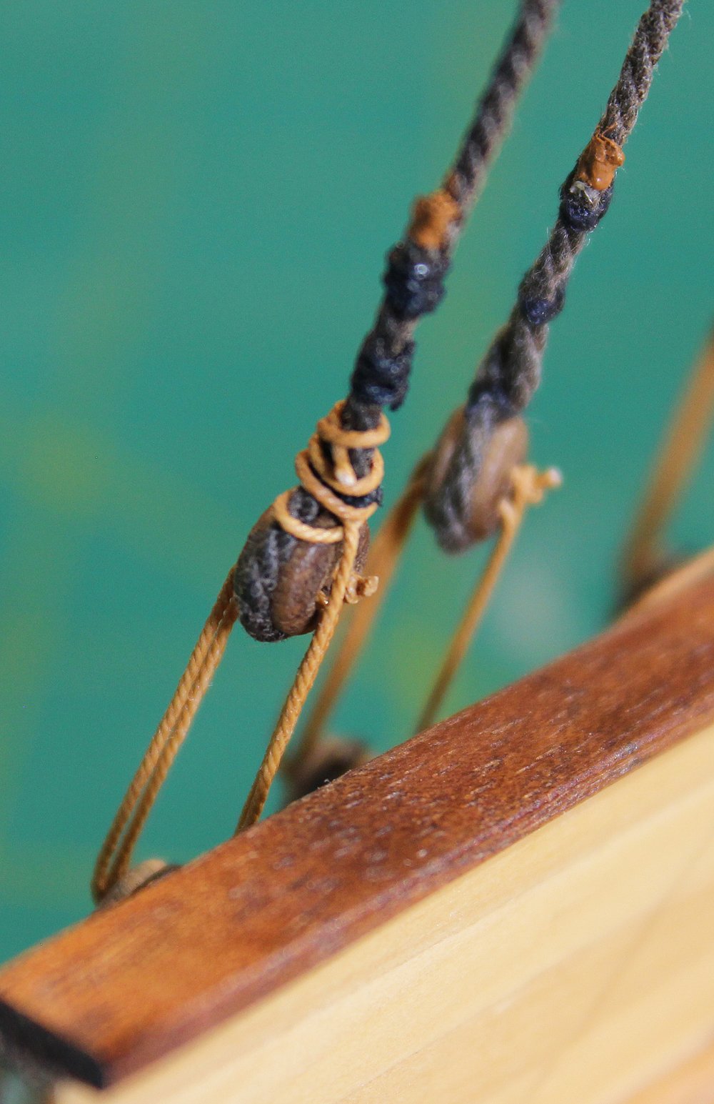
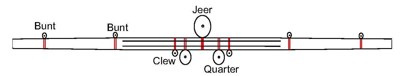
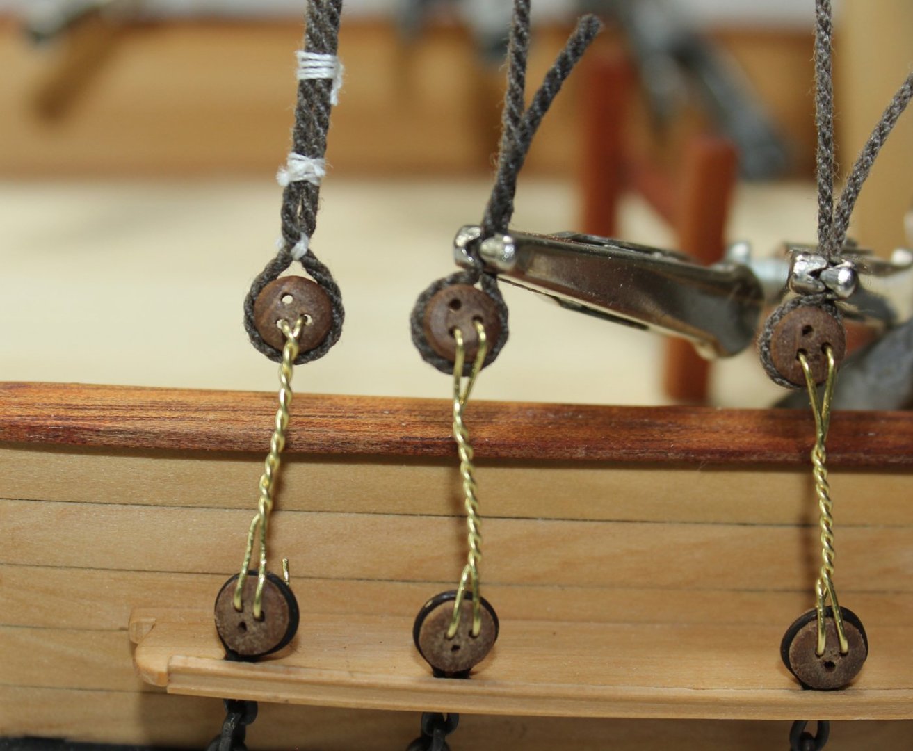
 The lower yard is specified on the plans as 41.5 feet long, with a centerline diameter of 9.2”. Just like the mast, the yard is divided into quarters. There are four quarters on either side of the centerline. The two center quarters are octagonal and the yard tapers from 9.2” to 7.8” at the end of the second quarter. Because this is a desktop model, I did not want the yard to extend beyond the side of the hull and made only the middle twenty-five feet. To make the yard, I started just like the mast, marking the dimensions on all four sides of the dowel. Because this is such a short piece of wood, a template was not necessary. The center octagonal section was made first. Then I wrapped tape around the center quarters to protect them and tapered the outer part of the yards. Finally, I rounded the tapered portions with sandpaper. The drawing illustrates the dimensions. A pin was placed in the center point of the yard to secure it to the mast. The yard sits at the level of the futtock stave so I drilled a corresponding hole in the mast. You can see the mast hole location in the picture in the previous post, just above the uppermost woolding. Nine blocks were installed on the yard. The jeer block is part of a pulley system to raise the yard. Its configuration changed several times in the eighteenth century and varied with different sized ships. This configuration is appropriate for a ship smaller than 28 guns in the last quarter of the 18th century. Quarter blocks carry the topsail sheet falls. Clew lines run from the corner of the lower sails (the clews) through the clew blocks. The buntlines raise the foot of the sail for furling and run through the bunt blocks. The quarter blocks were installed first. The kit will include 5 mm blocks; mine were slightly larger to be the correct length of 5.2 mm. These blocks are stropped with served line. This is my technique. Serve a piece of line that you think will be the right length; on my model this was 1.6”. This is running rigging so the serving thread is natural color. I used Gutterman sewing thread. Leave a long tail of serving thread on either end. The first step was to make a loop at one end. Untwist a short segment of rope next to the end of the serving on one side and cut the untwisted threads at a 45-degree angle to decrease the bulk. Form a loop, with the untwisted threads laying alongside the served part of the rope. With the tail of serving thread, wrap the untwisted threads and previously served line. In actual practice, the untwisted line would be laced into unserved rope and then the service would continue along the loop, terminating at the throat of the loop. Temporarily seize the block and measure how long the strop should be by wrapping it around the yard. The loop ends do not meet; a seizing will run between the loops to secure it to the yard. Make a kink in the rope to mark the spot. Remove the block and make the second loop the same way. Measure the length of the finished strop so you know how long to make the strop for the other side. Reinsert the block and secure it with a throat seizing. The seizing is located on the fore side of the mast and the block hangs below the mast. This picture incorrectly shows the legs the same length. Finally, the strop was wrapped around the yard and the two loops were seized together.
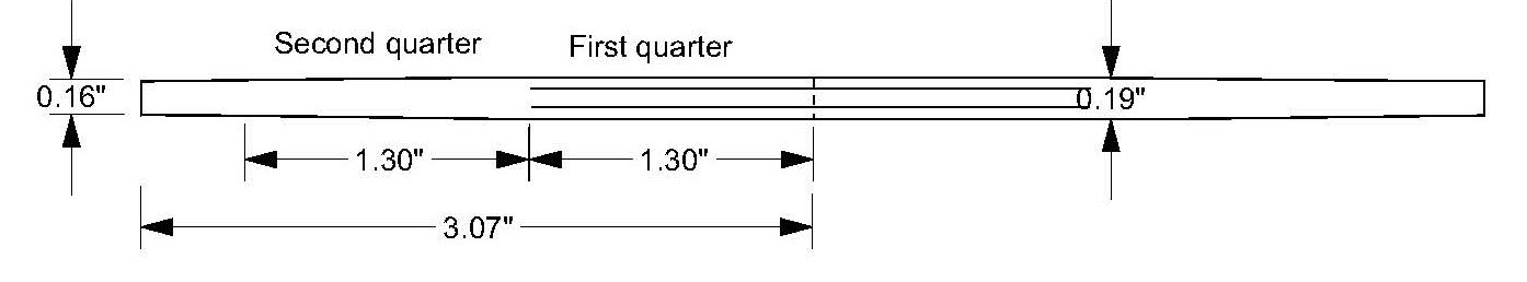

- 80 replies
-
- 25
-

-
- rigging/masts
- NRG
- (and 2 more)
-
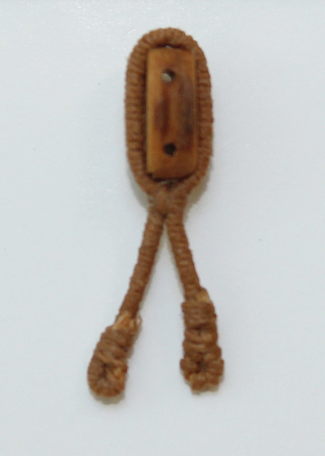
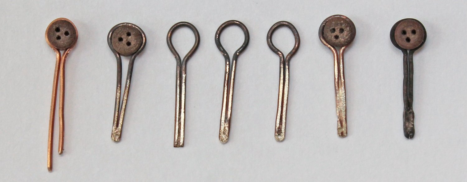
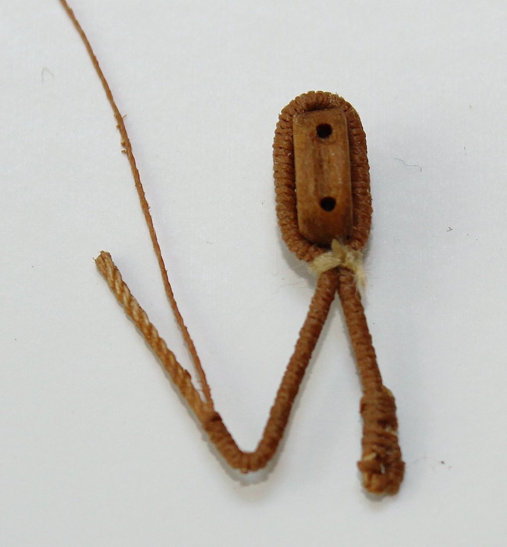
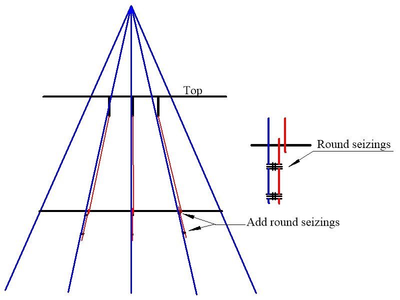
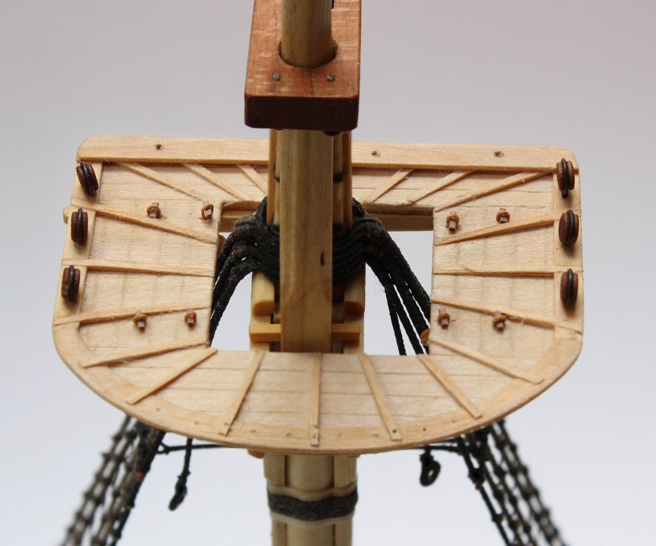
The futtock shrouds are attached to the futtock stave below and the futtock plate above. An eye with a thimble is spliced into the upper end of the futtock shroud. A double hook connects the shroud and the futtock plate. To make the stropped thimble, I took some line and unfurl the end. Using a blunt needle, I made an opening in the line approximately the circumference of the thimble away from where the unfurling stopped and fed the unfurled end through the opening. Once the line has been passed through the opening, the opening will naturally retwist itself. A piece of brass tube (the thimble) was inserted into the eye and the splice was glued. The thimble was blackened after it was stropped because handling would have caused the patina to rub off. The brass tube is slightly wider than the diameter of the rope. To keep the thimble from falling out of the splice, I placed it on an anvil and tapped each open end with a center punch. This added a slight lip to the thimble. The double S-hooks are 1/8” long and were made from 24 g wire, using round-nose pliers. The picture shows them attached to the futtock plates. The futtock shroud was attached to the futtock stave by wrapping around the stave and securing it to the lower shroud with two round seizings. In the drawing, the futtock shroud is shown in red and the lower shroud in blue. After they were installed four rows of ratlines were added.


- 80 replies
-
- 17
-
-

-
- rigging/masts
- NRG
- (and 2 more)
-
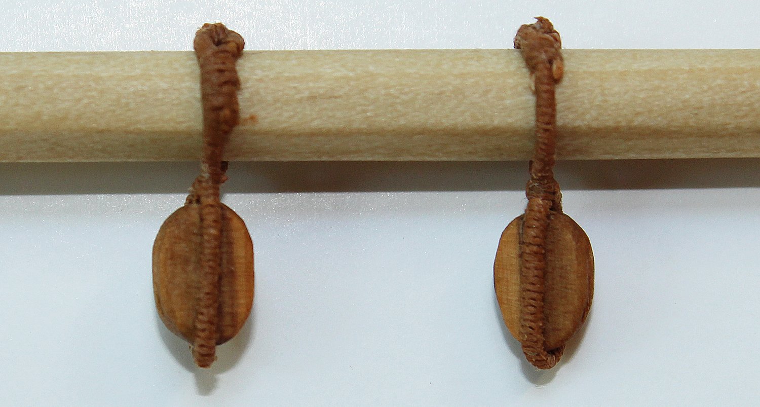
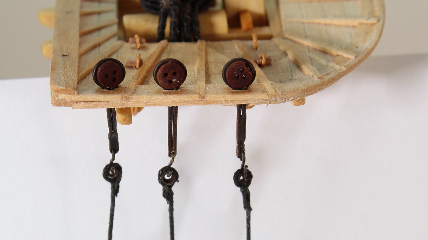
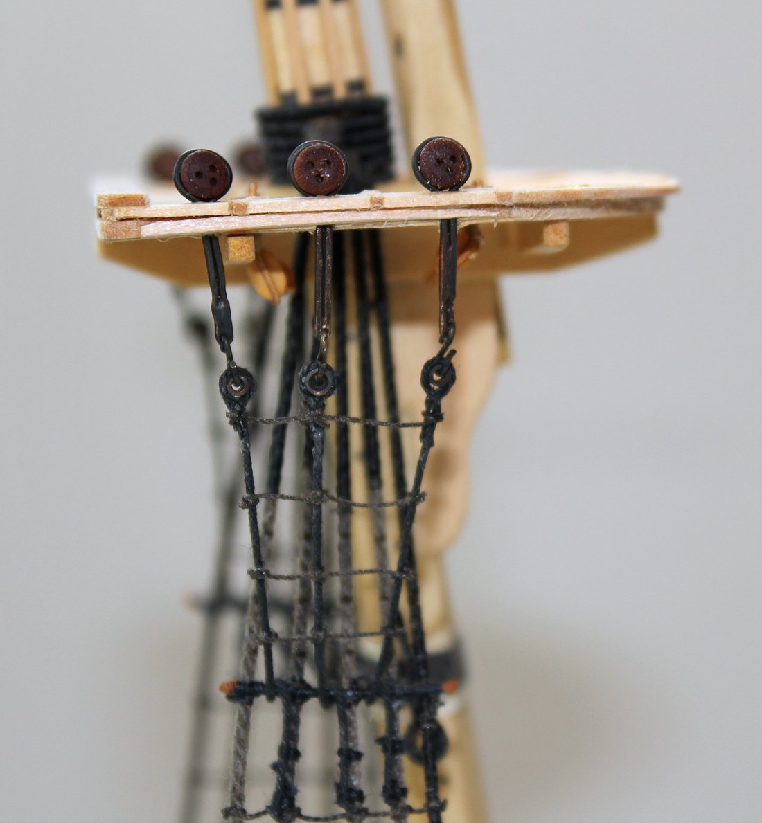
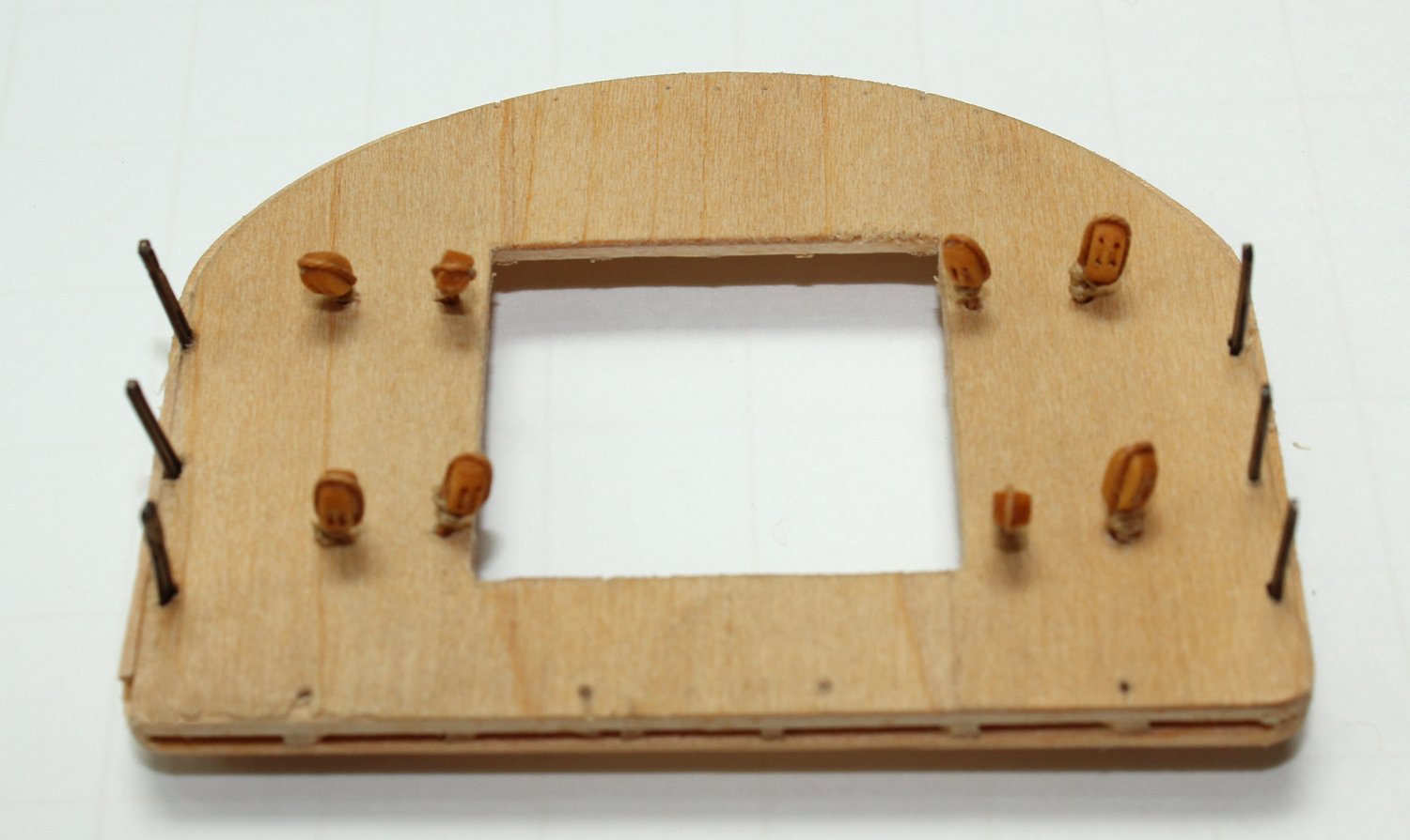
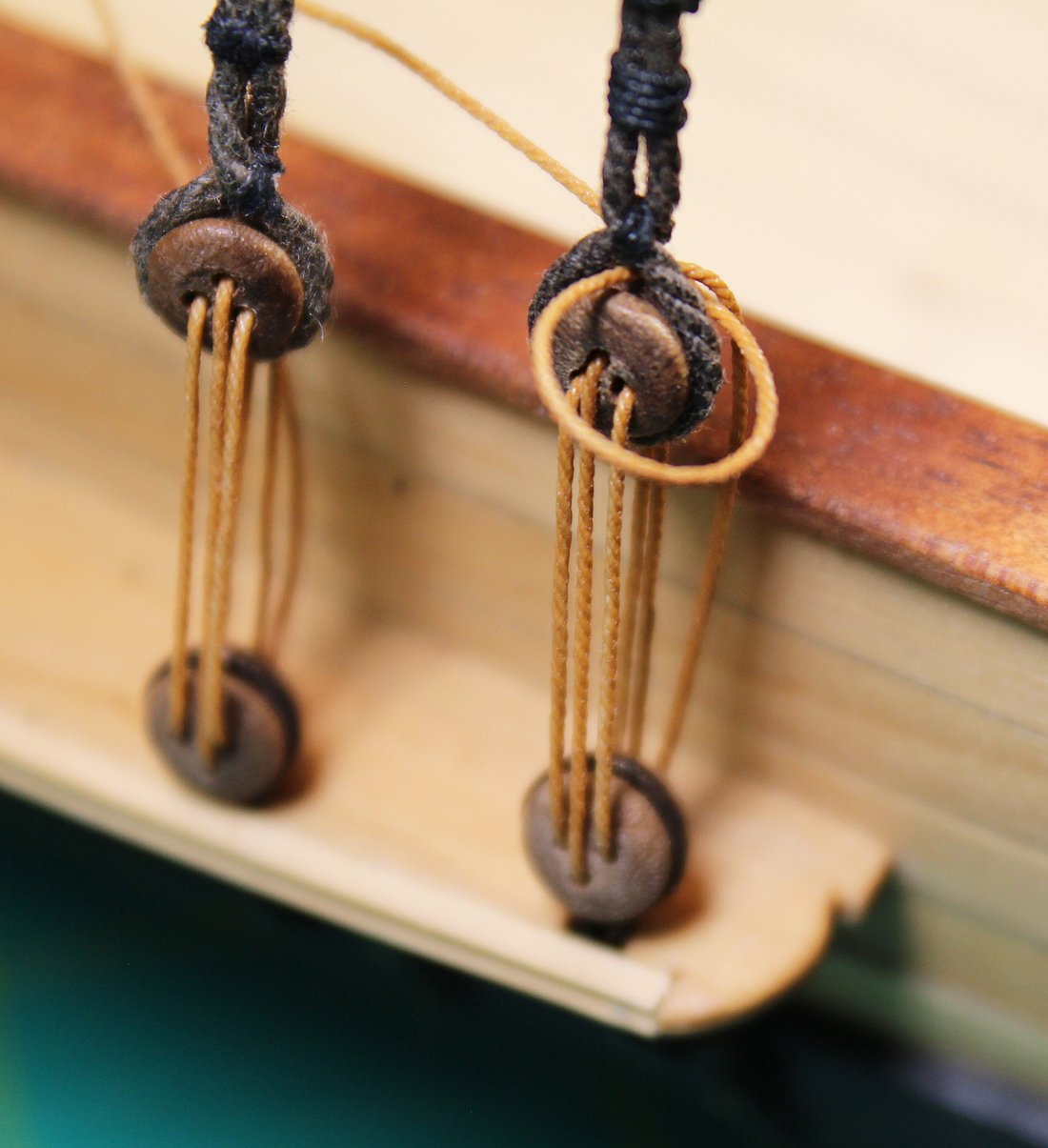
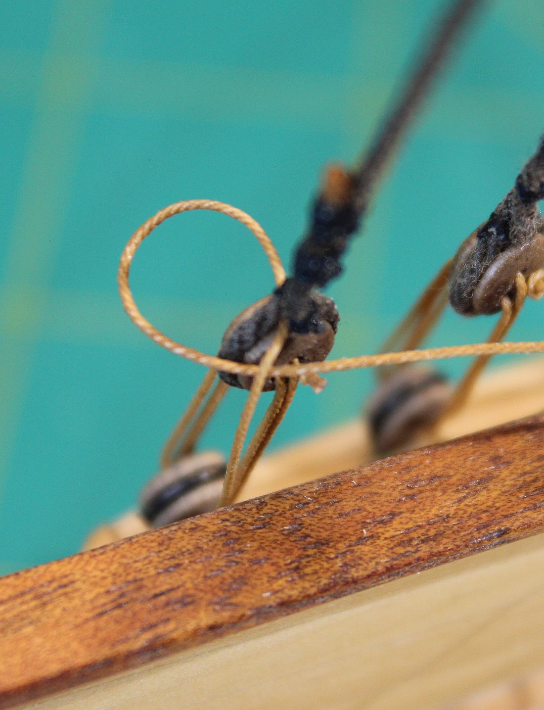
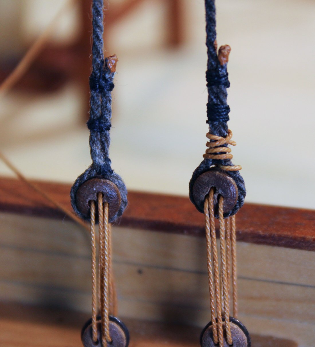
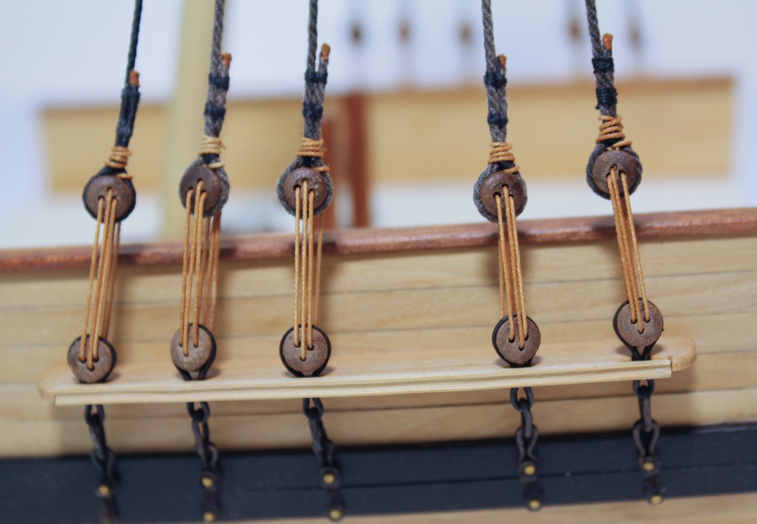
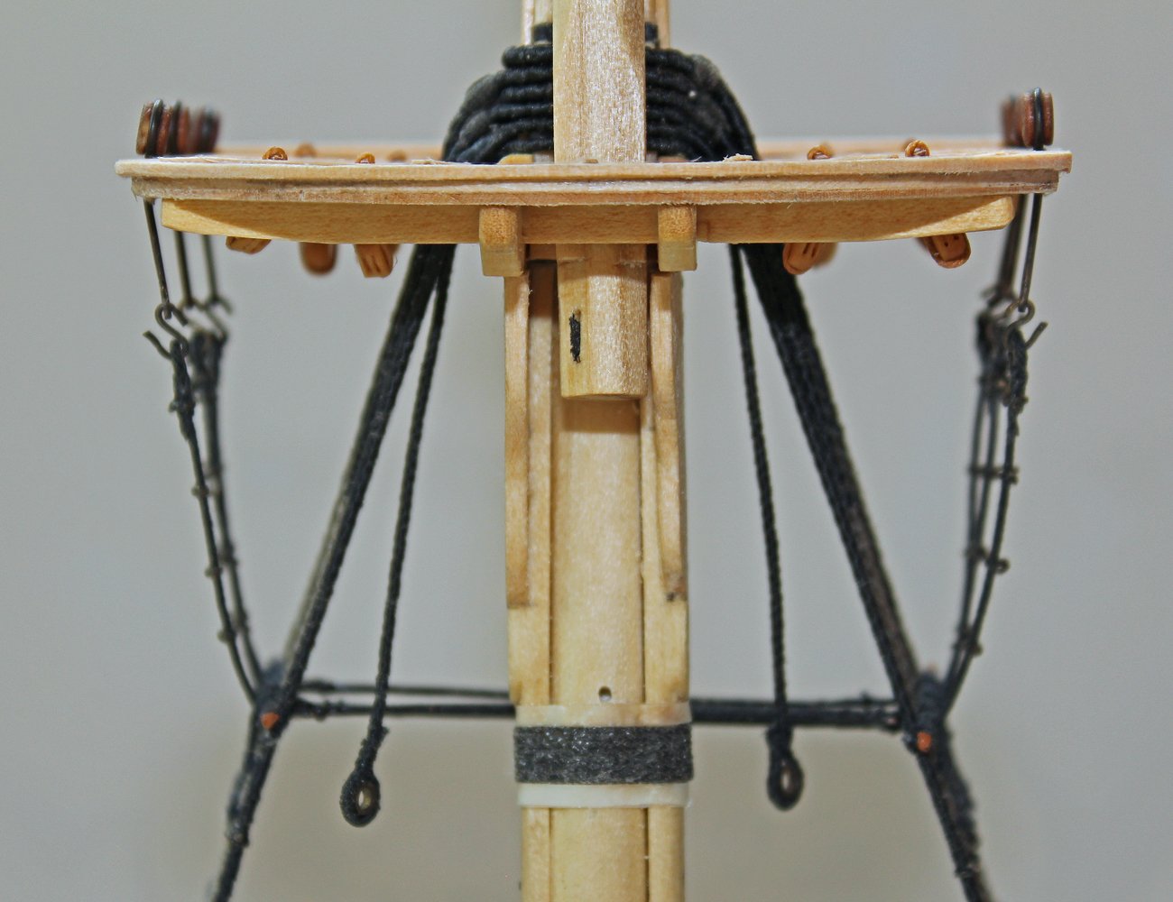
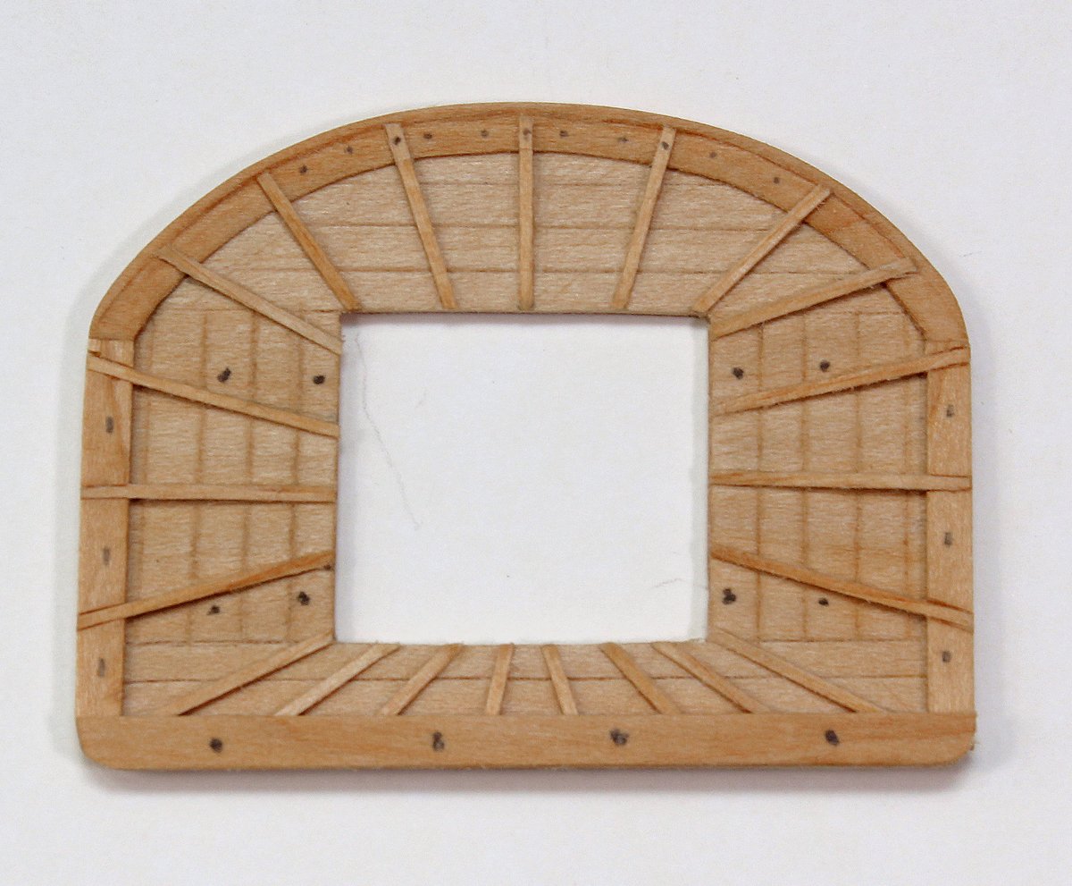
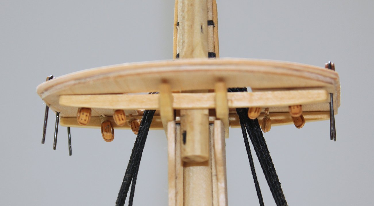
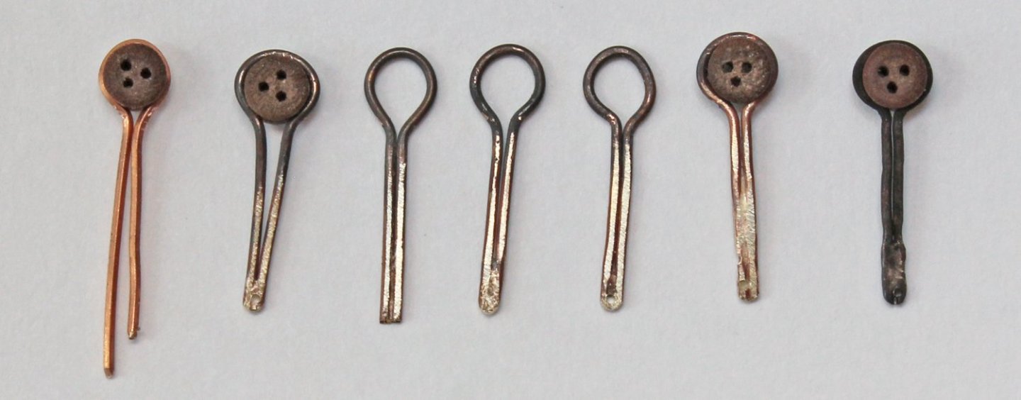
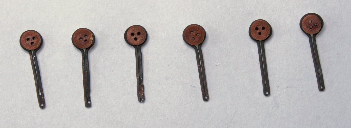
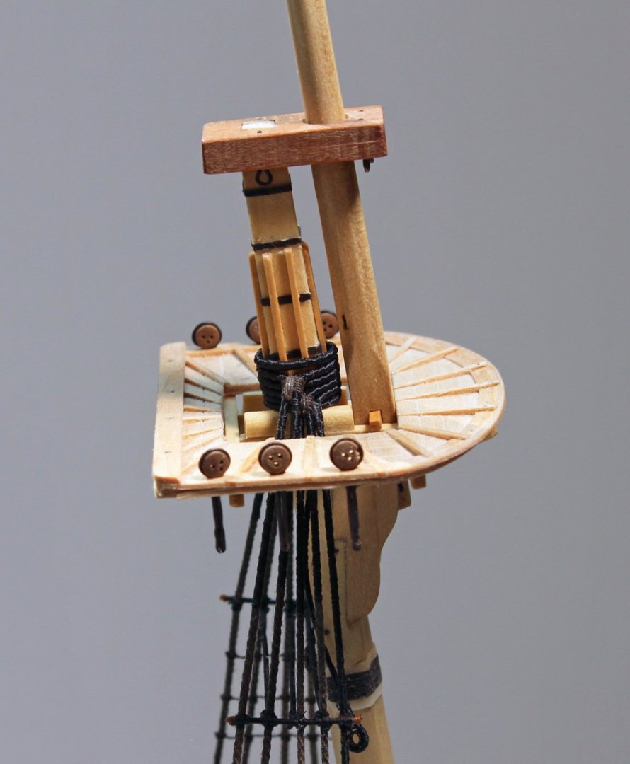
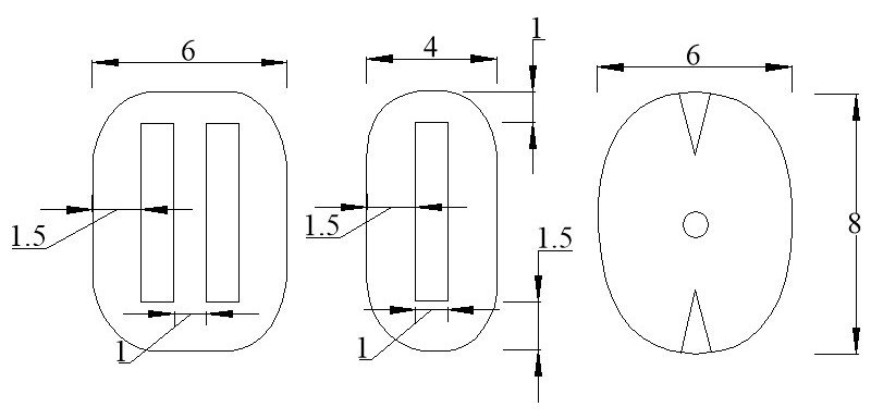
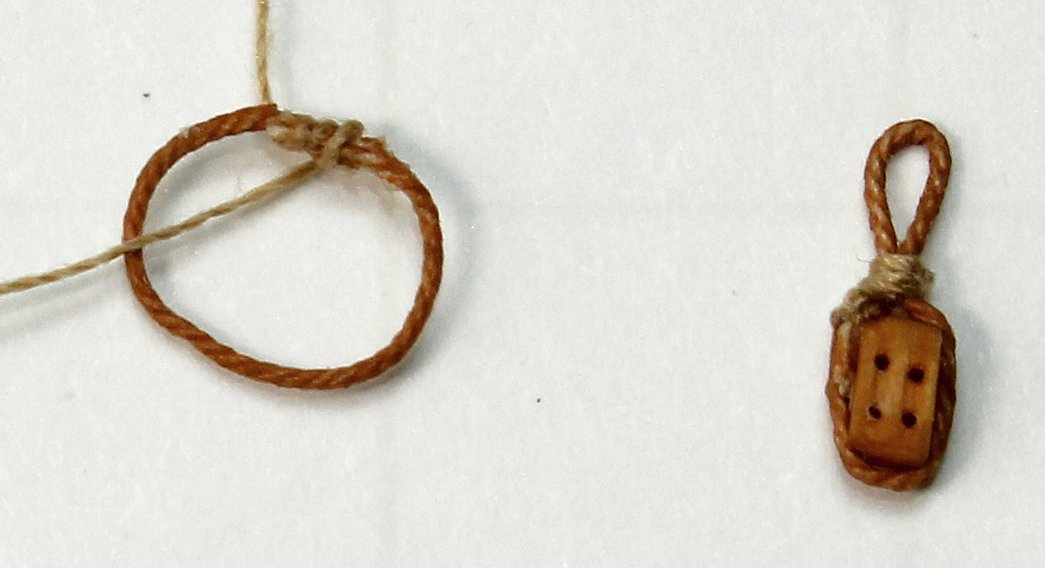
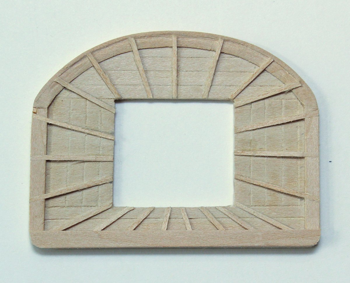
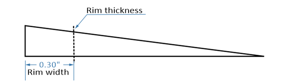
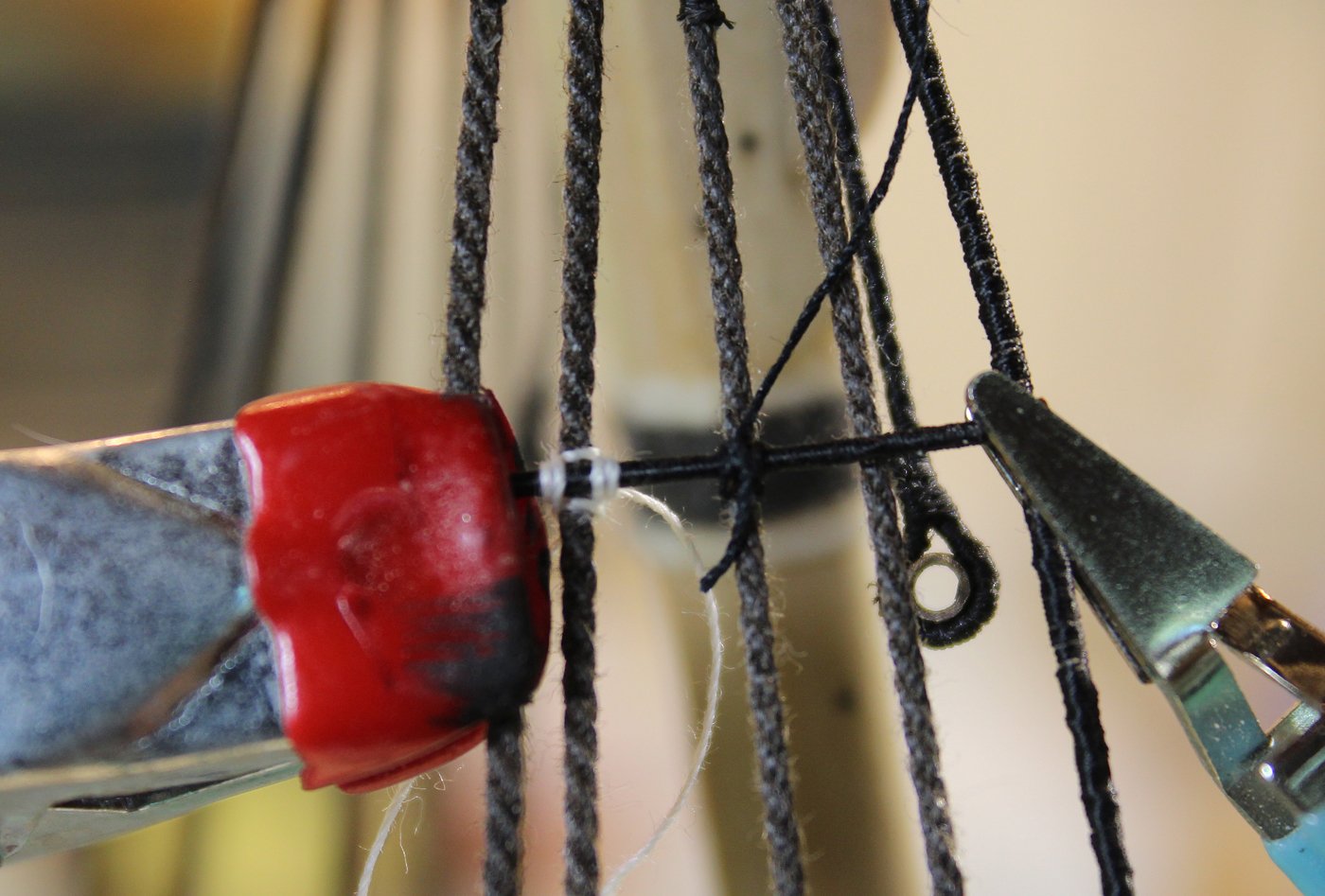
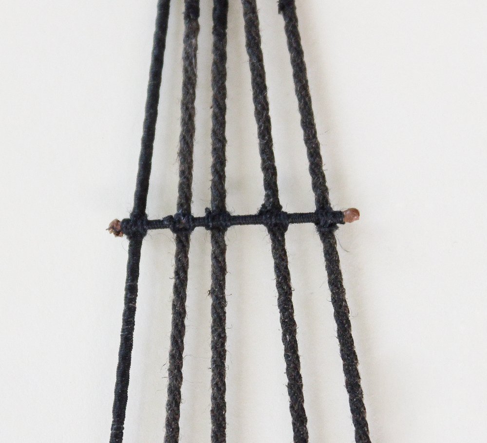
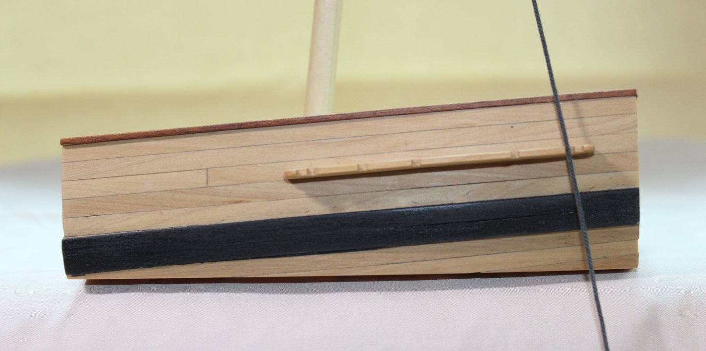
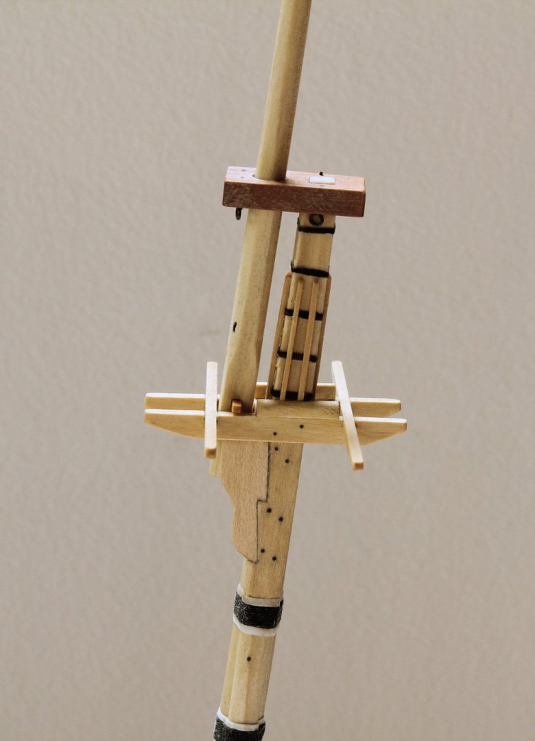
There are several holes in the top, which are marked in the picture below. On the curved rim are eleven holes for the crow’s feet: two between each slat and one through it. There are three rectangular openings on each side rim for the futtock plates. The four marks on the aft rim are for the railing stanchions. Finally, there are four openings on either side of the center opening for the buntline and leechline blocks. Futtock plates are the metal straps that surround the lower topmast deadeyes. The topmast shrouds are two-thirds the size of the lower mast shouds. The deadeyes are 3” thick and 6” in diameter. The futtock plate is one-third the thickness of the deadeye and three times its diameter long. At 1:48 scale, that would be .02” x 0.375”. They were made from 22 gauge wire. The sequence of construction can be seen in the photo. First, heat-soften the metal and wrap a piece around the deadeye. Remove the deadeye and solder the ends of the two legs together. Reinsert the deadeye to confirm the location of the throat and mark it with a Sharpie. Determine the correct length for the plate by measuring 0.375” down from the throat and mark this measurement as well. Remove the deadeye and solder the legs together closer to the throat. File the legs flat and cut the legs to the correct length. Round off the end and drill a hole for a hook to insert into. Pickle the plate and insert the deadeye. Hammer or squeeze the legs of the futtock plate together for a snug fit and blacken. The holes in the top were enlarged and the plates were temporarily inserted. Before the futtock shrouds can be installed, eight blocks must be stropped and installed on the undersurface of the top. All my blocks are made of boxwood. Blocks are not commercially available for all sizes. For example, the quarter and truss pendant blocks should be 6.5 mm but the closest available block is only 5mm. A good reason to learn how to make your own blocks! The kit comes complete with all of the necessary blocks except the jeer blocks, which the modeler will learn how to make. Determining the dimensions of blocks is not difficult; all you need to know is the size of the line that passes through it. The width of the sheave opening is 116% the diameter of the line. For simplicity, call that “1”. The relative dimensions are as seen in the drawing below. The only difference between a single and a double or triple block is/are the spacers between the sheaves The size of the strop grooves on the sides of the block varied; the relative size of the strop decreased as the size of the block increased. There are four leech line and four bunt line double blocks mounted under the top. The bunt line blocks are closer to the center opening and the leech line blocks are closer to the rim. The difference in the size of the blocks is small, so the kit will use the same size blocks for both. They are secured to the top with a strop and peg. To make the strop, I took a piece of 1” rope and untwisted both ends. I cut across each untwisted end diagonally to decrease the thickness of the splice, wrapped the two ends together and glued the splice. A simple knot was placed over the splice. The block was inserted into the strop and secured with a throat seizing, hiding the splice. The openings in the top were enlarged with a #11 blade, working from both sides of the top. A thread was passed through the strop loop and both ends of the thread were inserted through the under surface of the top, pulling the strop through the top. Wood pegs were used to hold the strops in place. The futtock plates were inserted through the openings in the rim.


- 80 replies
-
- 23
-
-

-
- rigging/masts
- NRG
- (and 2 more)
-
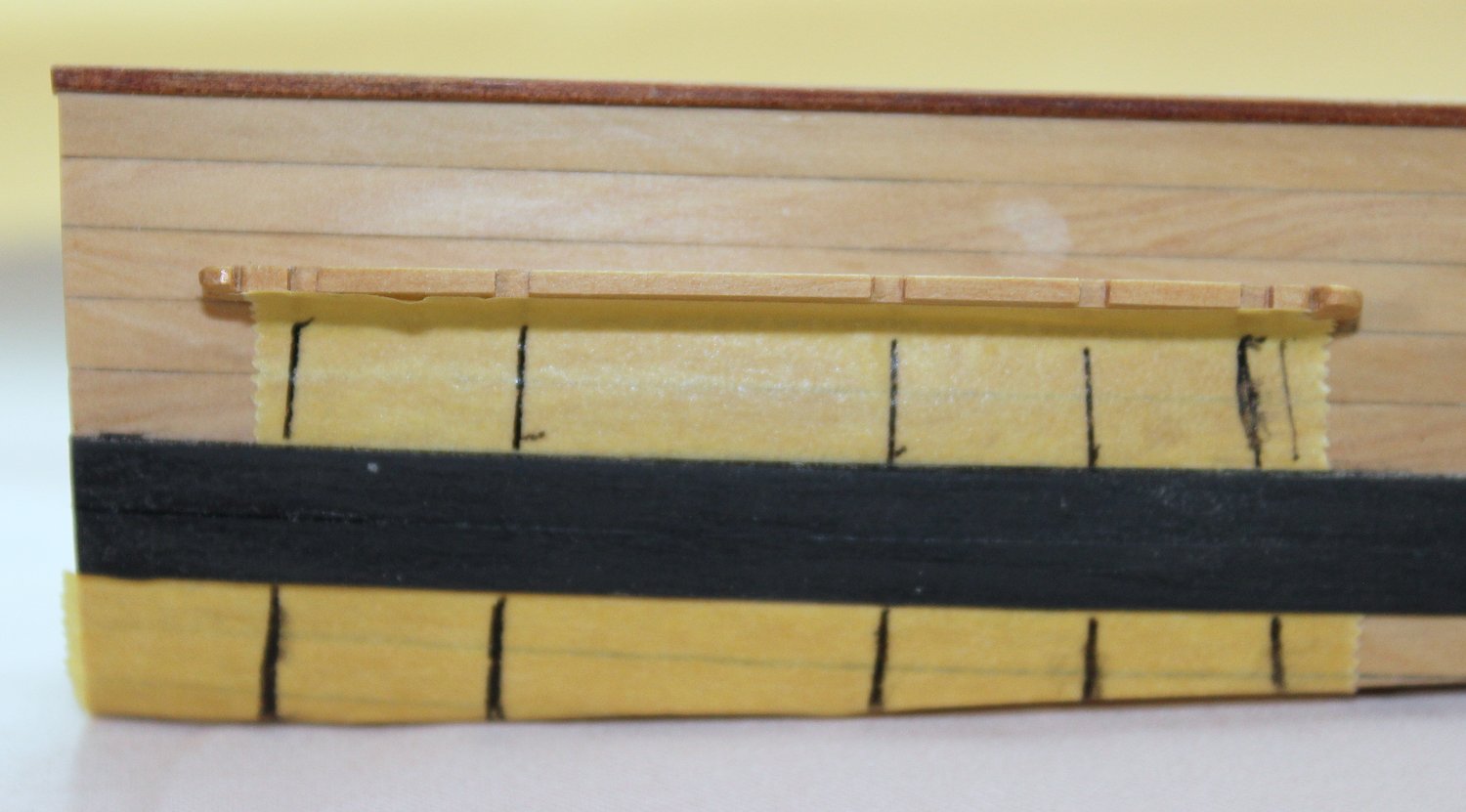
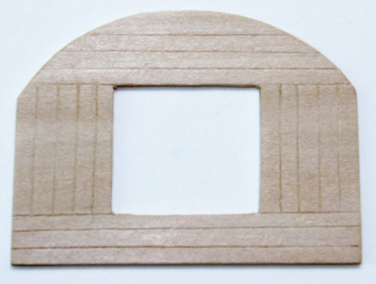
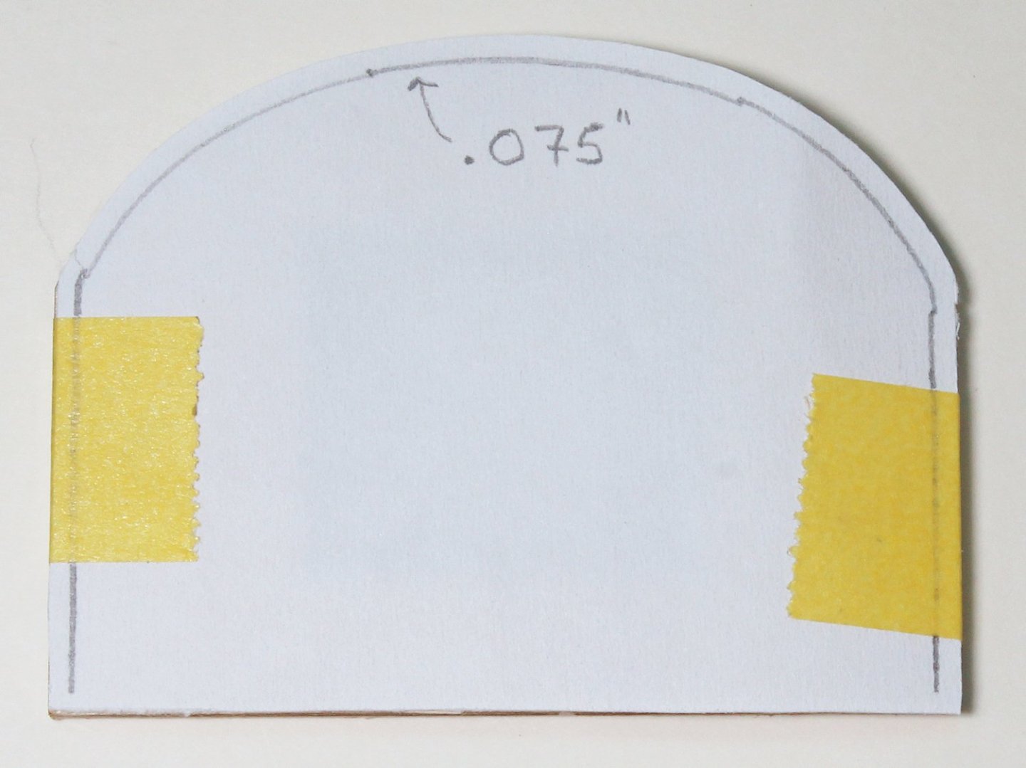
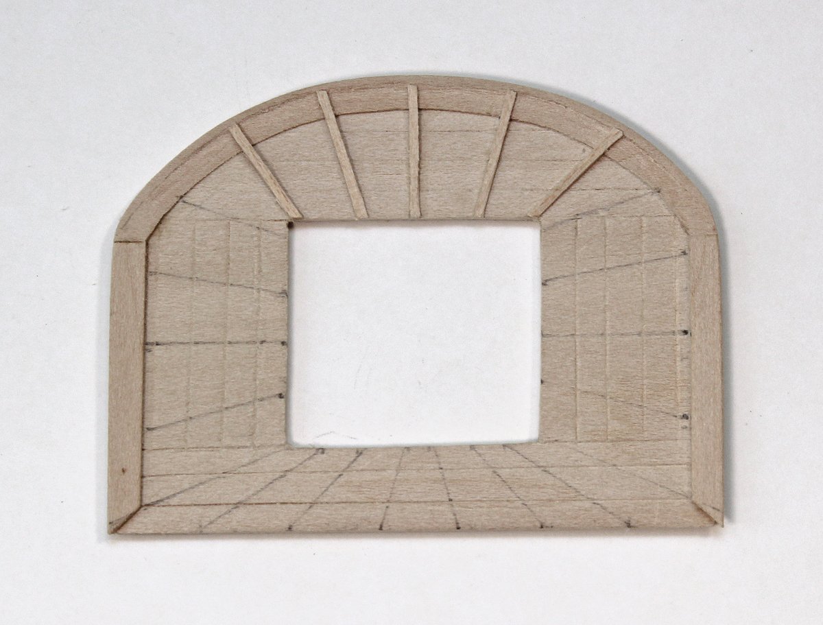
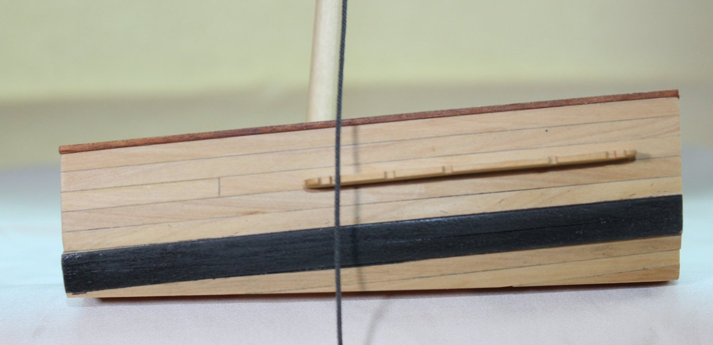
I made the top by laminating two layers of 1/32” basswood sheeting, each at 90 degrees to each other. The kit will have a plywood template to trace the shape onto the basswood. This gave the correct thickness and added strength. On a real ship, the top was made up from tongue and grooved wood slats. I drew the edges of the slats onto the top with a #11 blade. The top’s rim was made next. I used template to trace the curved section onto sheet basswood. The rim overlaps the edge of the top so draw another line onto the basswood 3.5” outwards from the first line. I made a second template by outlining the top and drew another line 3.5” inwards from the edge of the template on the curved edge and both sides. The template was trimmed at the inner line (see arrow below) and positioned on the basswood sheet 7” inwards from the first line. This gave me the shape of the curved part of the rim. The rim was glued onto the top and weighted down until dry. The front edge of the rim is raised. I used a 3 mm chisel to remove one-third of the thickness of the rim. If you do not have a chisel, you could use a sanding stick to shape the rim. The inner edge of the rim was feathered so that only one-third the thickness was left where it met the top. The side pieces also they extend 3.5” beyond the edge of the top and their thickness tapers to one third the thickness on its inside edge. Because this piece is straight and with the grain, the tapering was done before it was glued to the top. When you turn the top upside down, you can see the overhanging edges fore and both sides. The top has multiple slats extending from the edge to the center opening. The number depends on the size of the top. I have penciled in the locations of the slats for this top (see two pictures down). The slats that abut the curved portion of the rim have an unusual shape. They are cut away to allow them to rest on top of the rim and tapered to a point as they approach the center opening. Since they are all slightly different in shape, they were made individually. The slat does not extend over the raised edge. In the next picture I have incorrectly cut the side edges with a 45 degree bevel. It should be a straight cut. The side slats pass through openings cut into the rim, and taper towards the center opening. I laminated six pieces of wood together and shaped them into a triangle. The height of the slat is flush with the rim. The slats were unglued, openings were cut into the rim and they were installed. The aft slats are also triangular and extend to the edge of the top. Lastly, a gunwale was glued on top of the aft slats and the side rim. Take a look at this much later picture to see the relationships between the gunwale, side rim and aft slats.

- 80 replies
-
- 23
-
-
-
- rigging/masts
- NRG
- (and 2 more)
-
I use a straight needle with a blunt tip. This is the kind typically used in counted cross-stitch.
- 80 replies
-
- 6
-
-
- rigging/masts
- NRG
- (and 2 more)
-
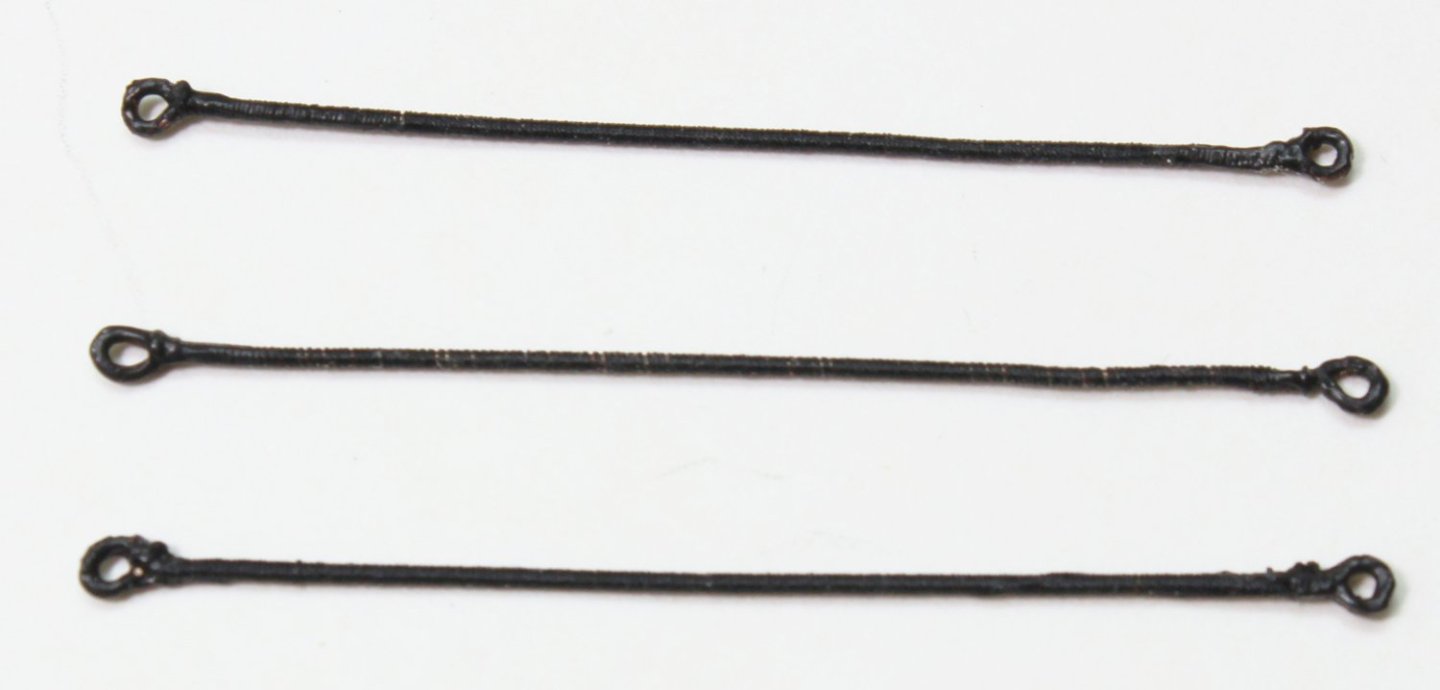
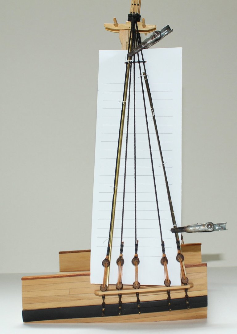
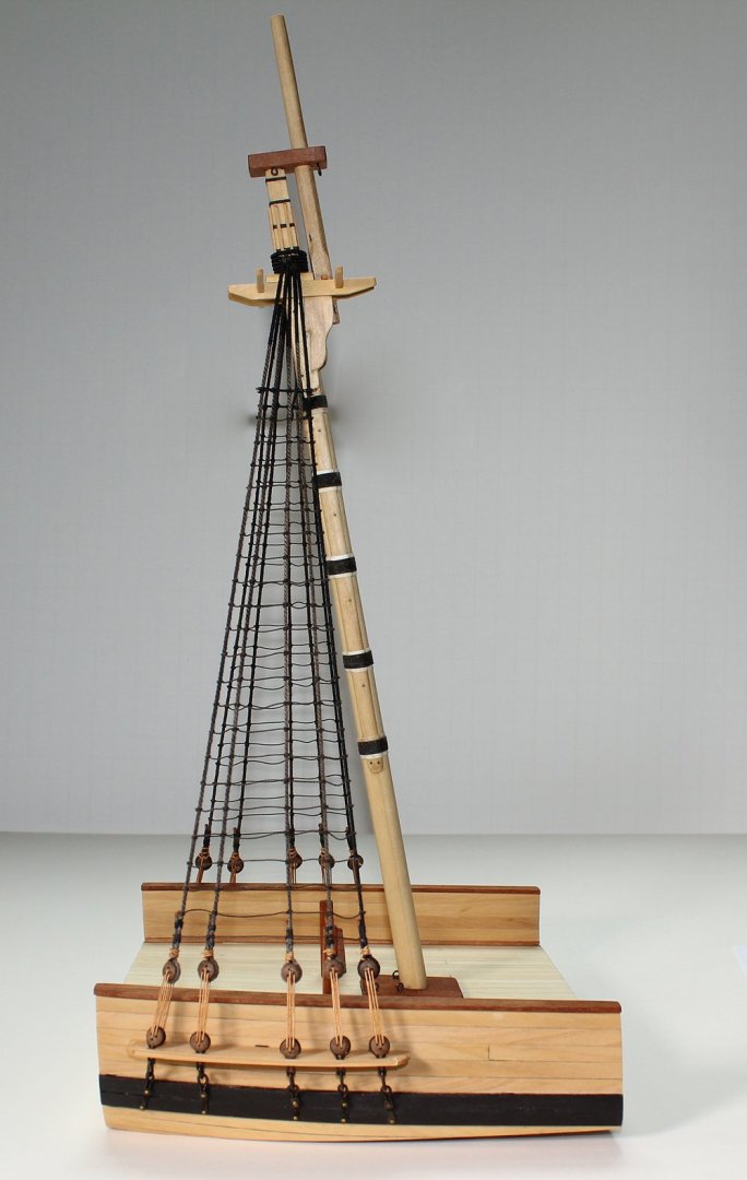
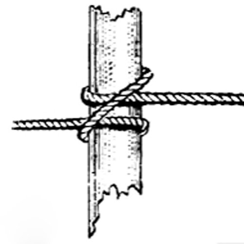
The futtock staves were made from 3” served rope and are located as far below the trestle trees as the top of the mast is above the trestle trees, approximately seven feet. For ease of installation, I used served 24 gauge wire, rather than rope. They were lashed to the shrouds. The picture on the left shows the lashing in white for clarity and the finished product on the right. And now it is time for the dreaded ratlines. There are some lines on a ship that are a do not change with the size of the ship, such as the footropes and ratlines, both of which must hold a seaman’s weight. The ratlines are made of tarred 1.5” rope. At this scale, I simply tied, rather than lashed, them to the outer shrouds. They are secured to the inner shrouds with clove hitch knots, a drawing of which is below. This picture is also from The Boy’s Manual. Ratlines are spaced 12-15” apart and are parallel to the waterline. The easiest way to keep them even is to make a line jig. There is a tendency to pull the shrouds inward as the ratlines are added. I like to secure a brass rod or stick to the outer shrouds to keep them straight. This is my setup. The clips are holding the line jig in place. The ratlines are parallel to the waterline, not to the deck. After several hours, 220 knots and fifteen scale feet of rope, the ratlines were finished. Catharpins are ropes with an eye at each end which extend across and are seized to the shrouds at the level of the futtock staves. According to Steel, sloops were not equipped with catharpins but I included them in the kit to illustrate their construction. I made them from 22 gauge wire with a loop on each end. As there is no tension on them, I did not solder the loops closed. The catharpins are served and the ends are painted black to simulate the eye splice. The first catharpin is located just aft of the mast and the other two are spaced out evenly along the futtock stave. This completed the standing rigging of the lower mast. As mentioned earlier, because this is a cross section model, lines that would not terminate on the model, such as the stays and backstays, were omitted.
- 80 replies
-
- 22
-
-
-
- rigging/masts
- NRG
- (and 2 more)
-
Or in easy to read tables here https://thenrgstore.org/collections/books-and-practicums/products/steels-tables-of-the-dimensions-of-a-ship-of-each-class-in-the-british-navy
-
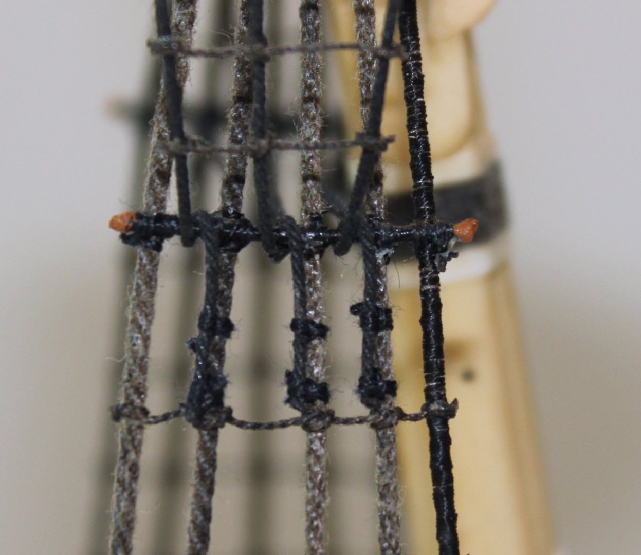
The shrouds were installed next. The starboard shroud is always placed first and are they are installed from fore to aft. Because this ship has an odd number of shrouds, the first shroud is single; the rest are double. The first shroud is served its entire length, protecting it from the lower sail. The starboard and port first shrouds are secured to each other with a cut splice, just as was done with the pendant tackle. The remaining paired shrouds are served where they could be chafed: the center 20-25%, based on the ship being rigged. I cut a two foot piece of line and marked the midpoint and 10% the length of the shroud on either side of the midpoint, in this case 1.2”. This is the area that was served. The doubled shrouds were secured with a throat seizing tight to the mast head. The lower ends of the served portion of the shrouds should be level when they are installed. This means that the throat seizing is not exactly in the middle of the served section, but offset enough to allow this to occur. You can see this in the next picture. The aft shroud seizing is slightly longer than the fore. The shrouds were installed, alternating starboard and port, taking care to stack them neatly. The topmast is temporarily installed in the following pictures. The next step was to attach the upper deadeyes to the shrouds. The distance between the upper and lower deadeyes is a constant. The easiest way to ensure this is to make a spacer jig. You will actually need ten, five for each side. The picture shows two jigs. The one on the left is made by soldering the two wires together. The other one uses twisted wire. The prongs go through the two inner deadeye holes. I started by inserting the prongs through the upper holes of the lower deadeye and bent the wire around the back of the deadeye to prevent it from coming out. Next, I wrapped the shroud around the upper deadeye and adjusted the shroud length so that the upper deadeye could be threaded onto the jig. These shrouds are cable laid (left twist), so the short end of the shroud went on the aft side of the shroud. If the shrouds were rope (right twist), the short end would be on the fore side. I secured the shrouds to the deadeyes with alligator clips. I find it important to leave the model alone for several hours at this point. This allows the rope to stretch and helps prevent sagging in the future. The upper deadeyes are secured with three seizings. A cross seizing was placed where the shroud crossed over itself next to the deadeye. I marked the location of the cross seizing on both sides of the shroud and removed the deadeye. If left in, the loop is too big. After making the cross seizing, the deadeye was reinserted and the middle and end round seizings were added. The drawing shows a round seizing. And the picture illustrates the relative location of the seizings, using white thread to make it easier for you to see. Brown paint was used to represent the leather cap at the end of the shroud. The shroud lanyards were installed next. They are considered running rigging and are not tarred. A knot was tied at the end of the lanyard and it was inserted through the back of the upper deadeye in the foremost hole. After reeving it through the deadeye, excess line was kept for tying off. Once they were done, the lanyards were gradually tightened, making sure the mast was straight. Just like with the shrouds, I gave it a few hours to allow the line to stretch. To tie off the lanyard, the rope was passed between the shroud and the deadeye (below left) and looped under the last line of the lanyard (below right). The lanyard was wrapped around the shroud a few times and finished by inserting it under the last loop.


- 80 replies
-
- 23
-
-
-
- rigging/masts
- NRG
- (and 2 more)
-
Make the blocks you need. Although tedious, it is not hard and does not require any fancy tools...just wood, a pinvise/drill and a razor saw.
-
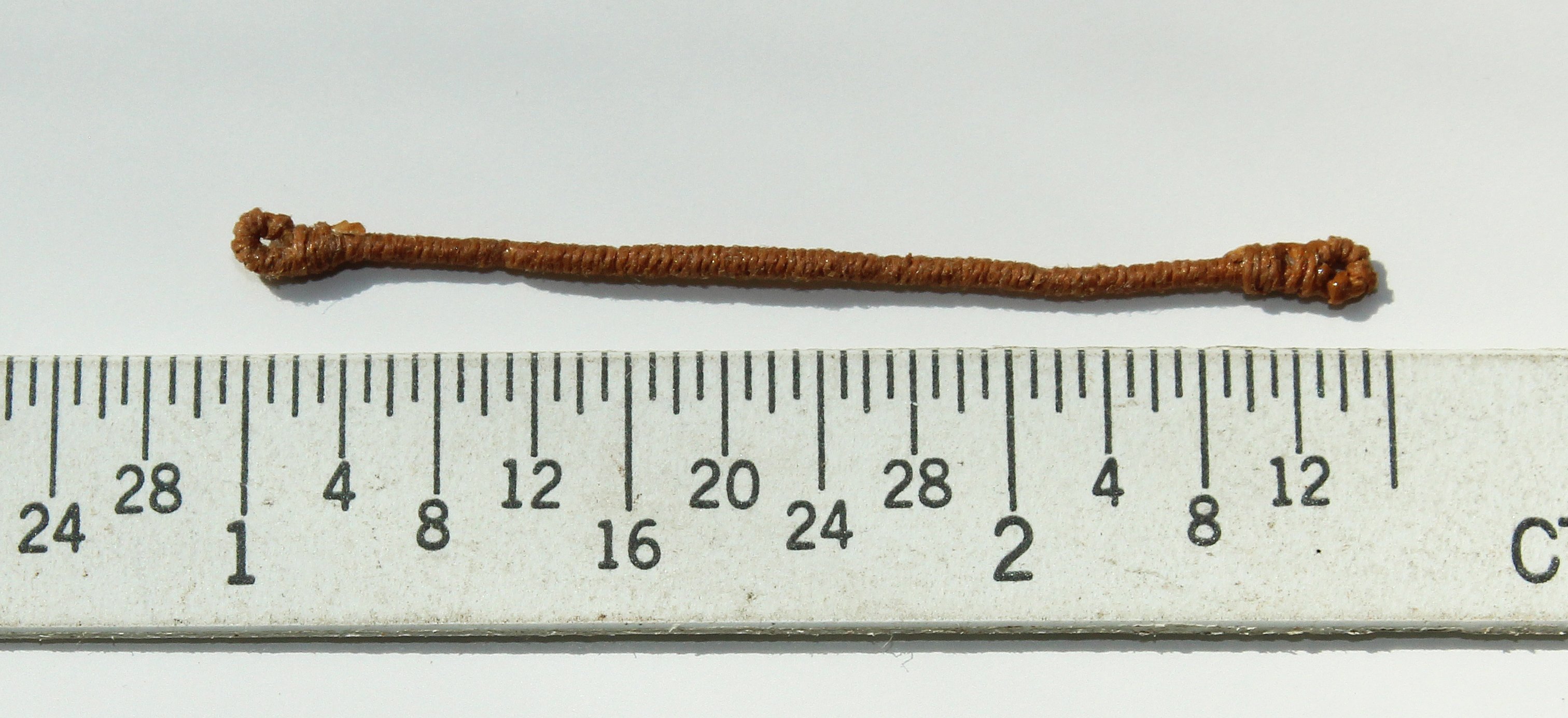
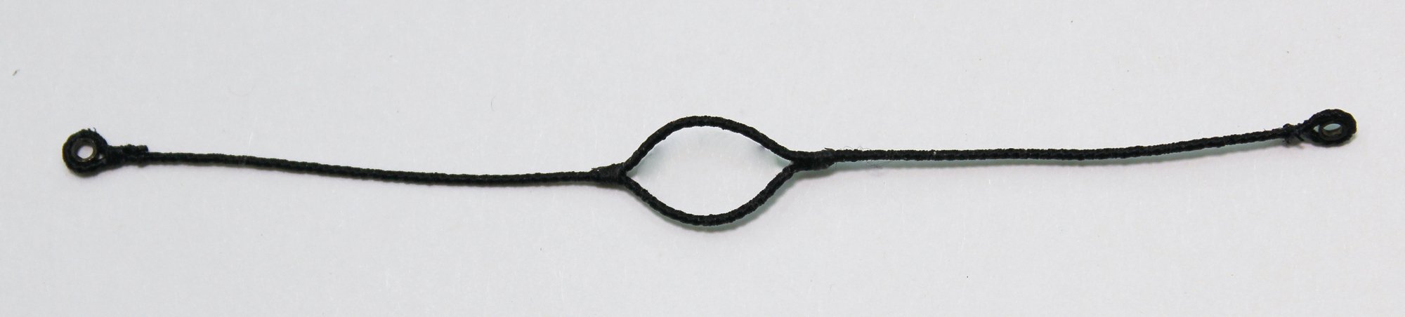
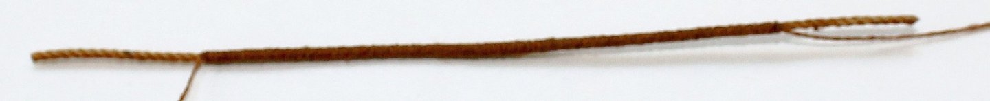
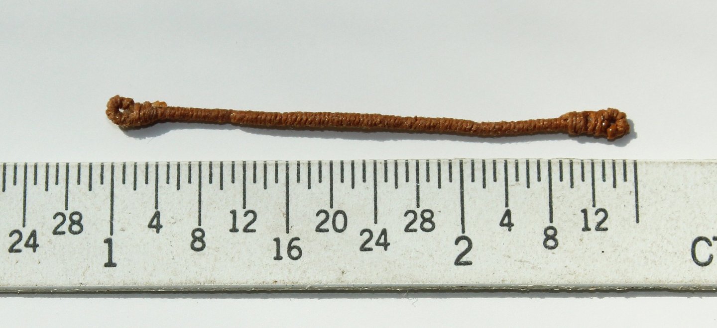
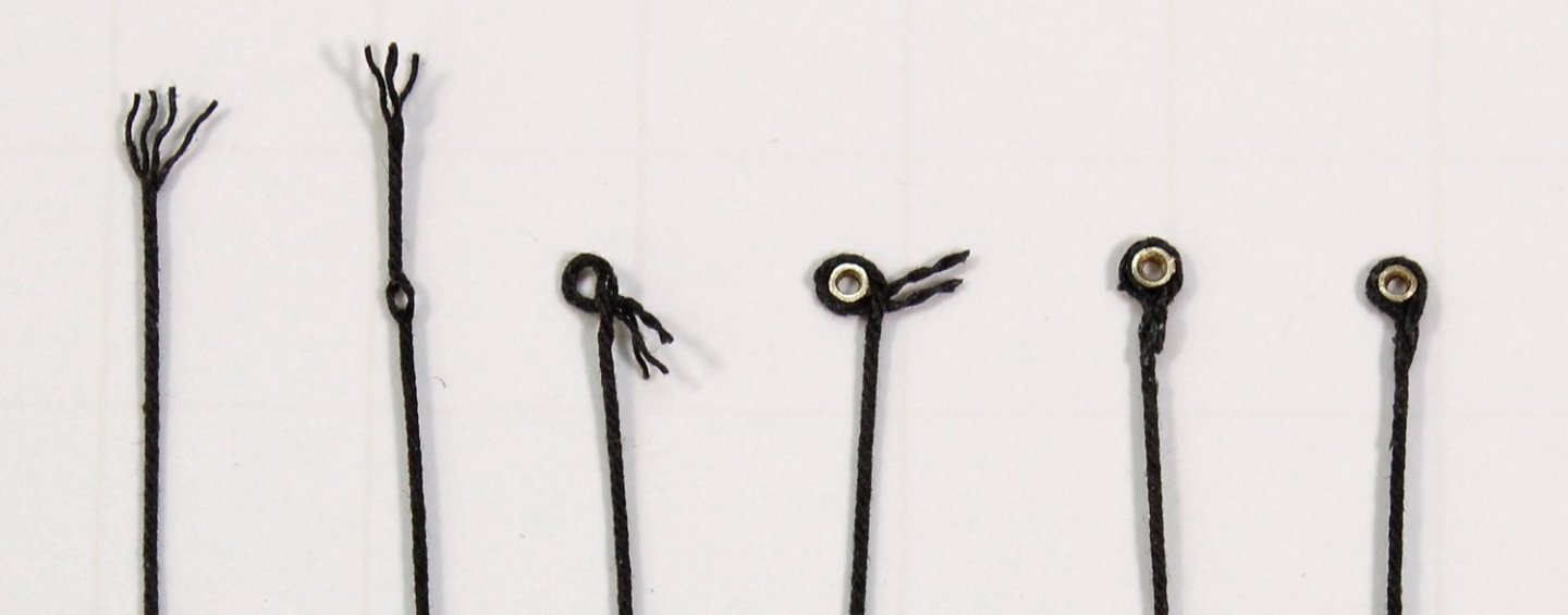
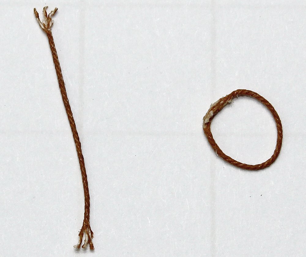
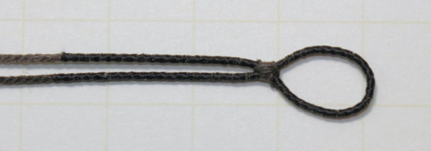
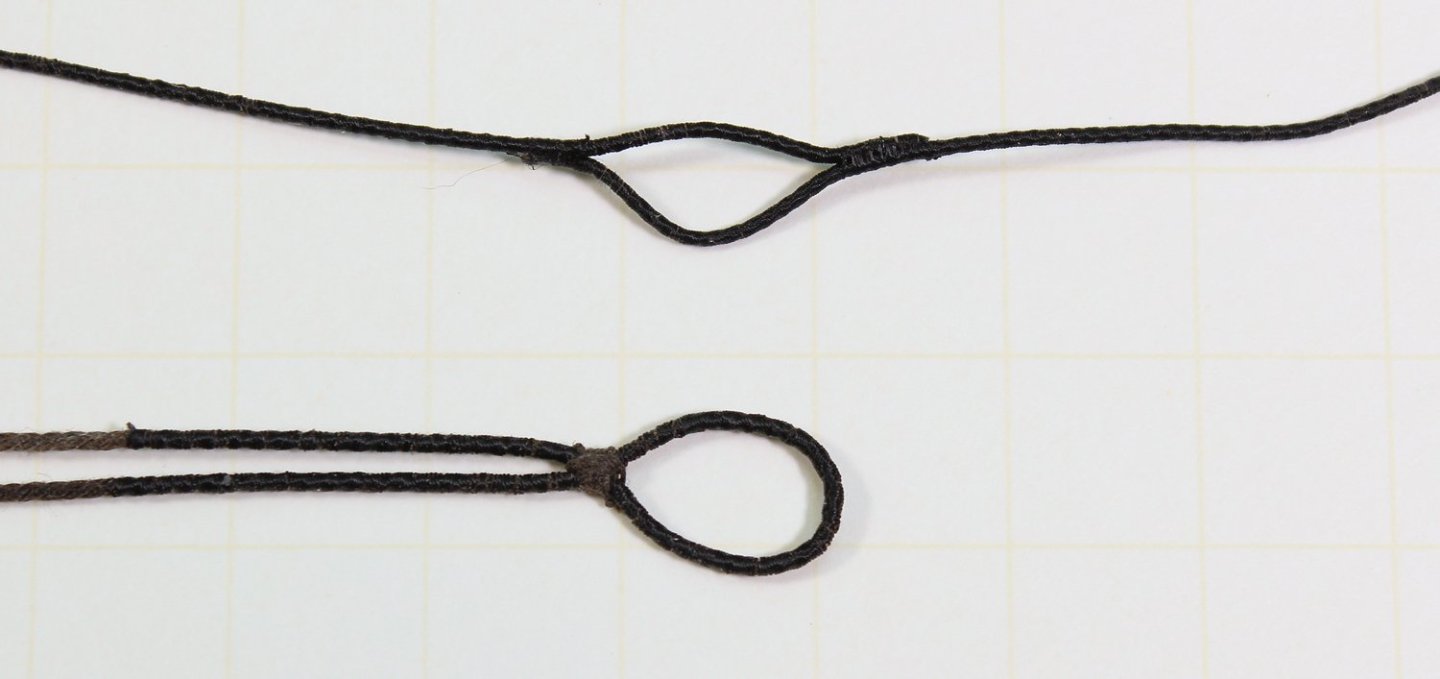
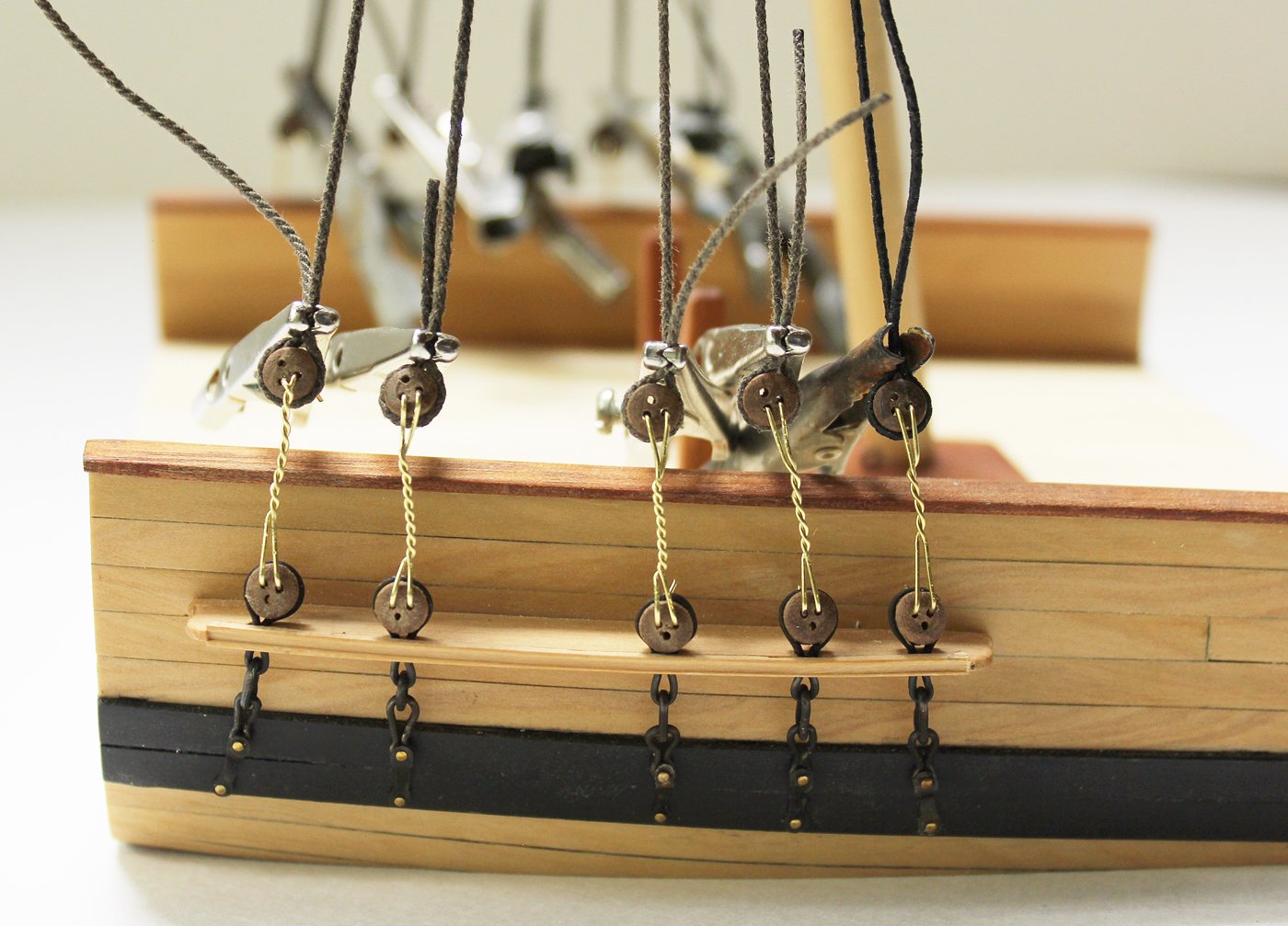
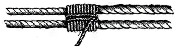
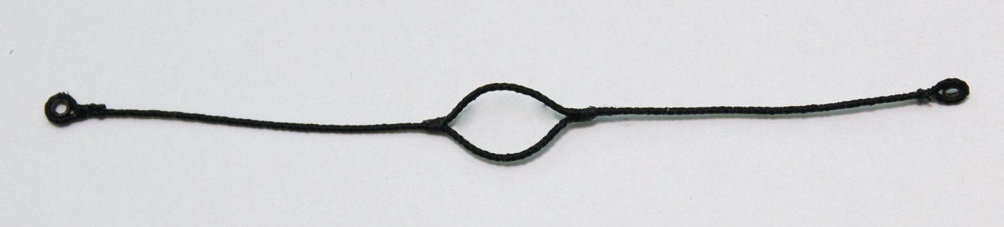
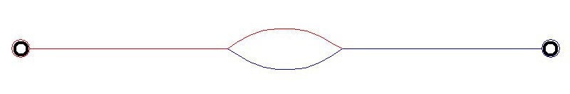
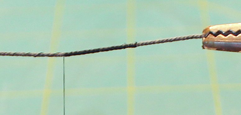
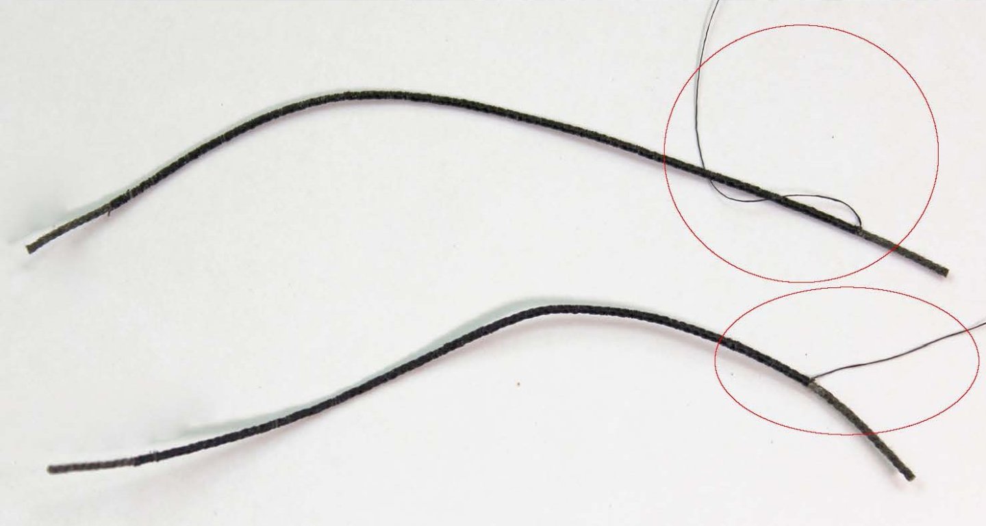
It is time to start rigging the mast. Some lines are served with an additional layer of line wrapped around them to protect them wherever they would be at risk of damage from rubbing. On this model, the pendant of tackles, the foremost shroud, the other shrouds above the catharpins and the jeer block strop are served. Because this is a cross-section, the main and back stays will not be installed but they would also be served. Standing rigging is protected from water damage with a tar-like compound. This resulted in a dark brown appearance to the lines. The running rigging was not protected and so was a natural hemp color. On this model, the burton pendants and shrouds are standing rigging; everything else is running rigging Rope sizes are calculated from the diameter of the mast. The kit contains a table with the dimensions for the various ropes, based on the diameter of the mast. To measure the diameter of the line, I wrap it around a dowel twenty times, measure the width of the wrapping and divide by twenty. This is much more accurate than trying to measure an individual line. The first rope to go over the masthead is the pendant of tackles. On the topmast, this line is referred to as the burton pendant. This rope is completely served, and has a thimble on one end. The other end is spliced to its opposite, resulting in the rope in the diagram below. Where the red and blue lines meet are splices. The pendants extend to approximately two feet below the hounds. They were used with a tackle to raise and lower heavy weights. To properly rig a model there is no substitute for the appearance of a served line. I use 6-0 fly tying thread, which can be purchased at a sporting goods store or online. I start by running thread, from left to right in this case, into the depression between the rope strands (worming), smoothing its surface (the yellow areas seen in the drawing below. Then I serve the rope from right to left. I find it easier to serve short segments of rope, such as this, on the same piece of rope and then cut them apart. I served the rope, leaving approximately six inches of serving thread for the splices (red circles). Then I made a diagonal cut, following the lay of the rope ¼” away from the end of the serving. The unserved line was held against the other line where the splice would go and I wrapped the two lines with the left-over serving thread “splicing” them together. I continued the wrapping a few more twists to smooth out the transition and tied it off. A tiny bit of dilute glue held everything together. The pendant was put over the mast head and onto the bolsters. It was marked on each leg, two feet below the hounds and removed from the mast. I used blackened 1/16” ID brass tubing for my thimbles. The mark was placed on the side of the thimble and the pendant was wrapped around it. For simplicity I used a simple seizing to secure the thimble and put it back on the mast.


- 80 replies
-
- 21
-
-
-
- rigging/masts
- NRG
- (and 2 more)
-
It is interesting to see the difference between the European and US/Canadian situations. In the States, there are few contests and a few non-competitive shows. Although some models are built by people who accept commissions, I would not describe them as professional modelers. Your Pegasus is beautiful and deserves to be appreciated by the modelling community.
-
Everything depended on the size and type of ship. This little ship only had a lower mast and topmast.
- 80 replies
-
- 6
-
-
- rigging/masts
- NRG
- (and 2 more)
-
Yes, the kit will have the lower topmast deadeyes. And yes, they are smaller. As I stated in my post above, "The diameter of the deadeye is 1.5 times the size of the shroud or stay it is attached to..." The topmast shrouds are 3.5", in contrast to the lower shrouds (5.5").
- 80 replies
-
- 5
-
-
-
- rigging/masts
- NRG
- (and 2 more)
-
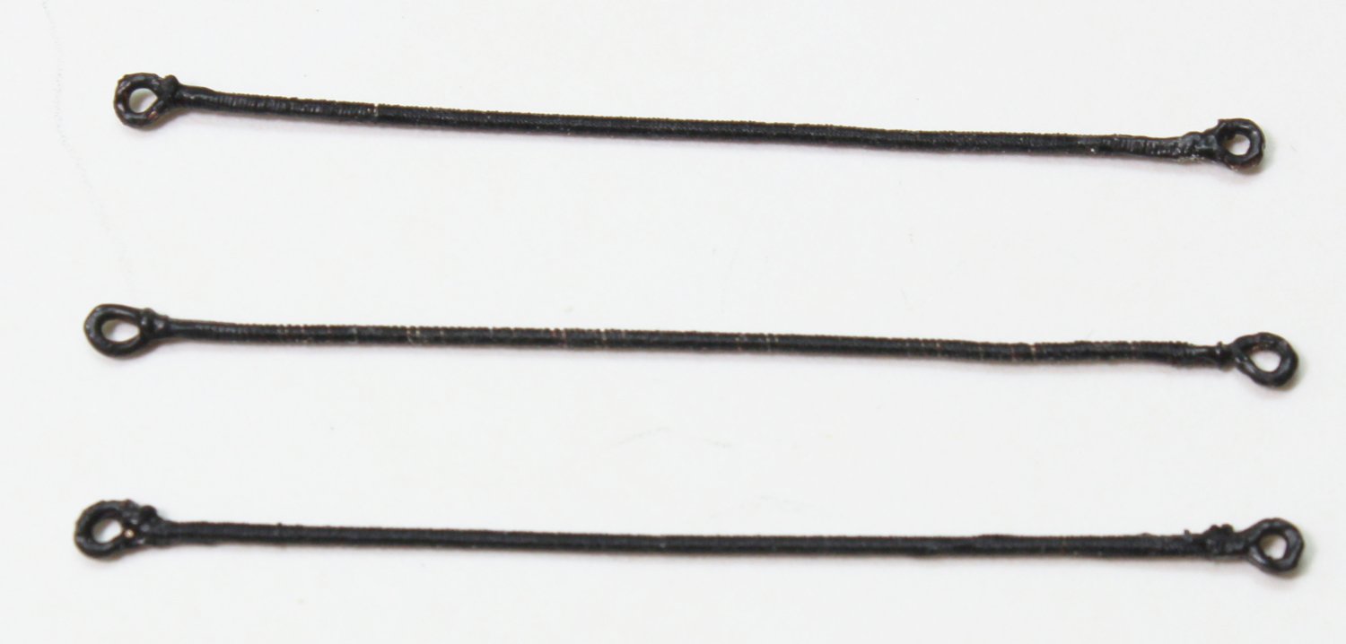
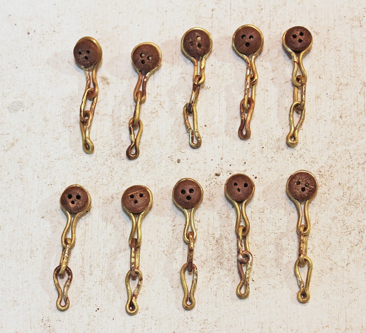
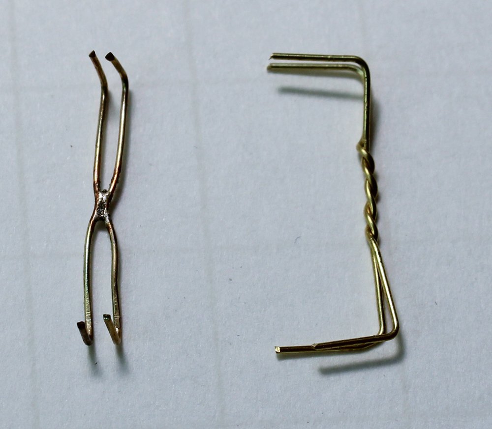
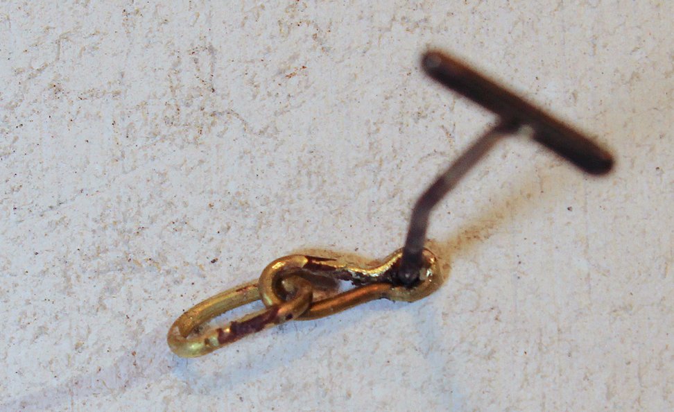
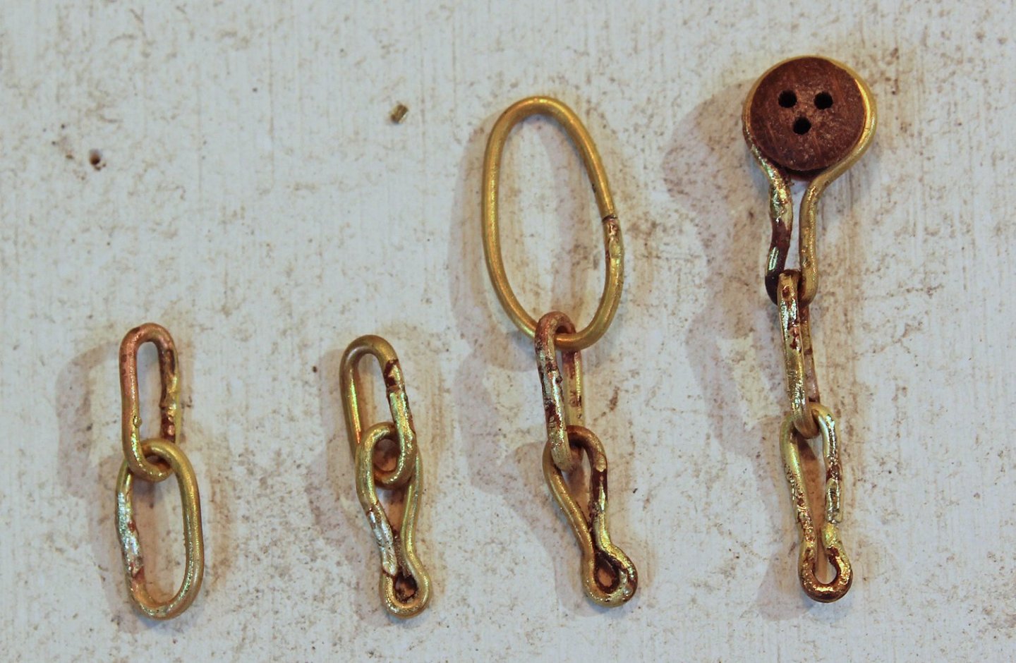
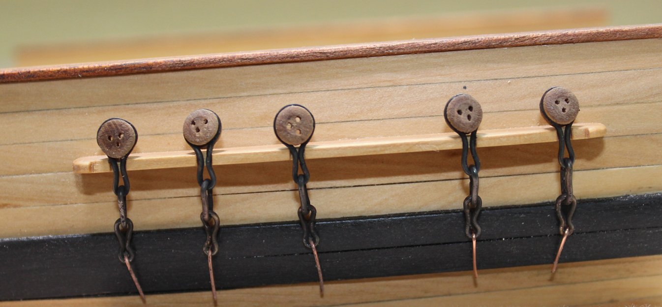
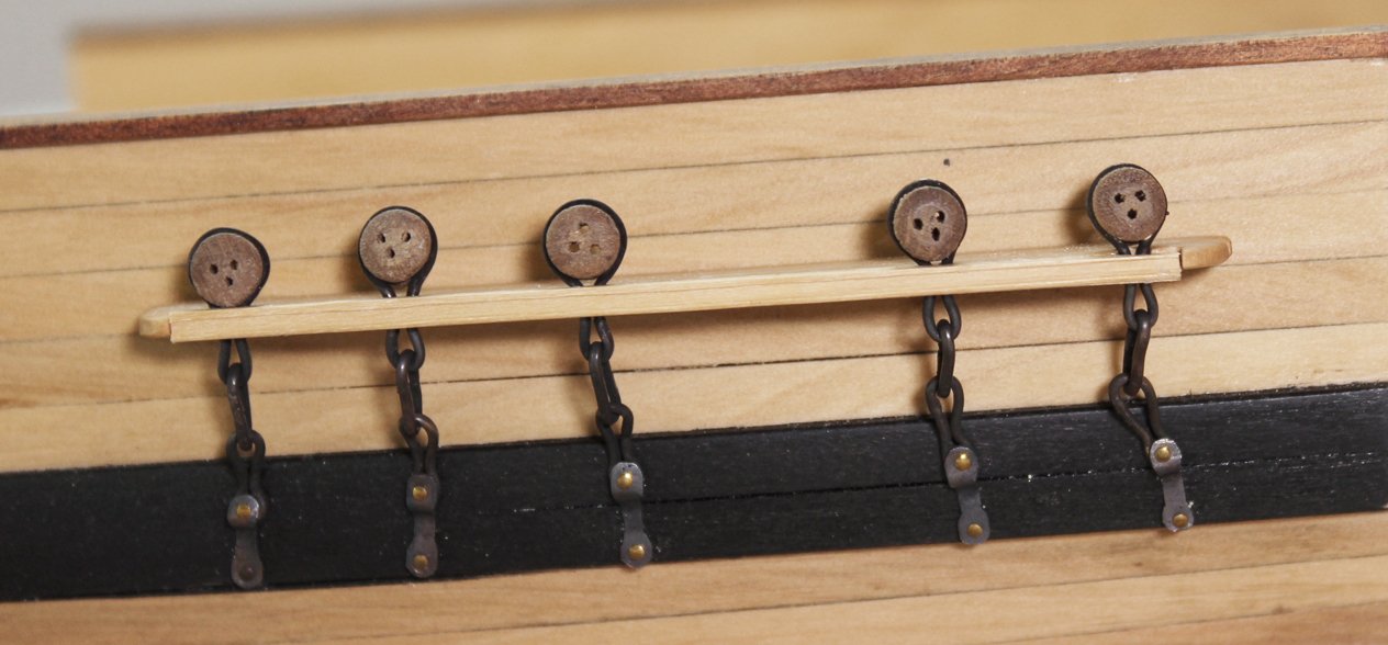
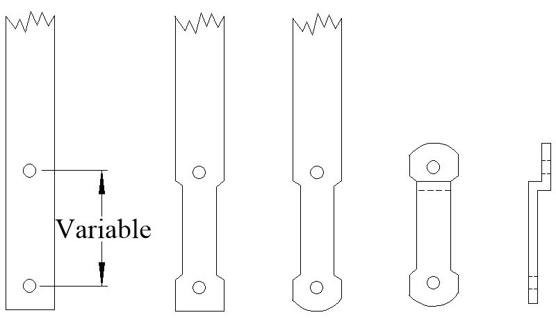
Most kits come with deadeyes and partially completed chains. Usually, the upper link (the link that goes around the deadeye) is pre-formed, with the bottom cut for insertion of the deadeye. Wire is provided for the builder to form the other two links but the entire assembly has very little strength and the cut ends of wire are ugly. The only way to make this assembly stronger and better looking is to solder the links closed. I prefer silver soldering, even though regular soldering will give sufficient strength. The benefit of silver soldering is that the metal is fused together rather than connected by a dissimilar metal, tin. This makes it easier to bend the part without worrying about the solder joint breaking. The downside is that there is a learning curve and the tools are more expensive. Silver solder also blackens well. There are also low melting point silver bearing solders (Tix) which can be blackened. The measurements for all the parts of a British warship were determined by the Admiralty. There are reference books that contain this information such as Steel’s Tables. An easily read version of the tables is sold in the NRG store. The main mast diameter is given on the plans as 18”. Using the information from the tables, I determined that the main stay is 9” and the shrouds are 5.5”. Lines are measured by their circumference. The diameter of the deadeye is 1.5 times the size of the shroud or stay it is attached to, in this case 8 ¼”. A spreadsheet comes in handy in determining all the measurements. Let me start by saying that my metal work has a bit to be desired. The chains are made from 1 ¼” wire, which is 22 gauge. I temper the wire by drawing it through a gas flame until it glows red. This makes the wire more malleable and removes any factory applied coating. The deadeye chain is the same length for all the deadeyes. Make one and use it as a template for the others. I wrapped wire around the deadeye, leaving long tails, and inserted this into the slot in the channel. The tails were cut long enough to be able form the loop below the channel. I removed the deadeye and applied a finish. The lower links are all the same length. From the plans I knew that the toe of the lower link is bolted 5” below the top of the wale and that its overall length was 9”. Two T-pins were inserted into the soldering board and the wire was wrapped around them, with the cut ends on the side. The middle link is different for every shroud because each is at a different angle to the mast as seen in the two pictures below. The link becomes longer with greater angulation of the shroud. You can see the difference in the shroud angles and how this would affect the length of the middle link. To determine the angle of the chains, I put masking tape on the hull above and below the channel. A loop of rope was placed over the mast head and inserted through a slot in the channel. The angles made by the shroud were transferred to the tape. I dimpled the wale where the toe of the lower link and the lower preventer chain bolts will be located and removed the tape. A hole was drilled through the wale where the toe of the lower link would later be bolted. The lower link and deadeye were temporarily installed. The length of the middle chains was determined by trial and error. With the deadeye and lower link in place, I formed the middle link from rope the same thickness as the wire and transferred those lengths to wire. I formed the middle link and soldered it closed, keeping the joint on one of the long sides. Then I inserted the lower link through the middle link and soldered it. A T-pin was pushed into the soldering board and used to form the lower link toe. The lower link is also bent at the toe, allowing it to lay flat against the wale. Finally, the wire for the upper link was passed through the middle link and soldered. The deadeye was inserted into the loop and the wire was crimped around it to fit into the channel slot, placing the solder joint in the slot camouflaged it. And here are the ten chains, ready for blackening. The blackening chemical did not damage the wood deadeyes. After blackening, the chains were installed. I have a piece of wire temporarily holding the lower link to the wale. The preventer plate prevents the bolt securing the lower link from going all the way through the toe. It was made from square bar stock that was forged to the correct shape. Mine are made from sheet brass, cut and filed to the correct shape. Just like the middle links, they varied in length. The top of the plate makes a step over the bottom of the lower link toe to cover it. To determine the distance between the bolt holes on the plate, I measured the distance between the toe bolt and the previously marked lower preventer plate bolt and added the diameter of the wire the link was made from. The sequence is shown in the drawing below. After they were finished, they were blackened and installed. To hold the upper links in the channels, a strip of molding was placed over them. Next up, the rigging begins.


- 80 replies
-
- 22
-
-
-
- rigging/masts
- NRG
- (and 2 more)
-
Thanks, Tom. Sorry for the delayed response but I was on the road and without internet access.
- 80 replies
-
- 4
-
-
- rigging/masts
- NRG
- (and 2 more)
-
At this point videos are not planned. There is more detail in the monograph and, if you purchase the kit, I would be available for questions. The Guild hopes to have it available in 4-6 weeks.
- 80 replies
-
- 12
-
-
-
- rigging/masts
- NRG
- (and 2 more)
-
HMS EURYALUS by Matiz - FINISHED - scale 1:56
tlevine replied to matiz's topic in - Build logs for subjects built 1801 - 1850
Congratulations on finishing this masterpiece. Looking forward to your next project. -
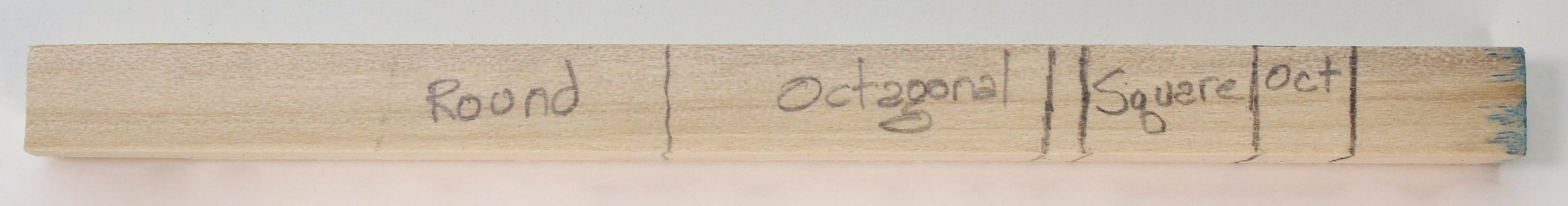
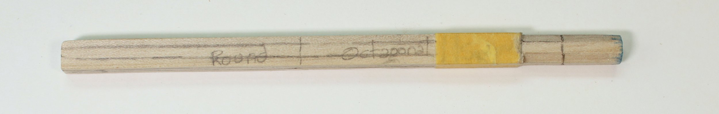
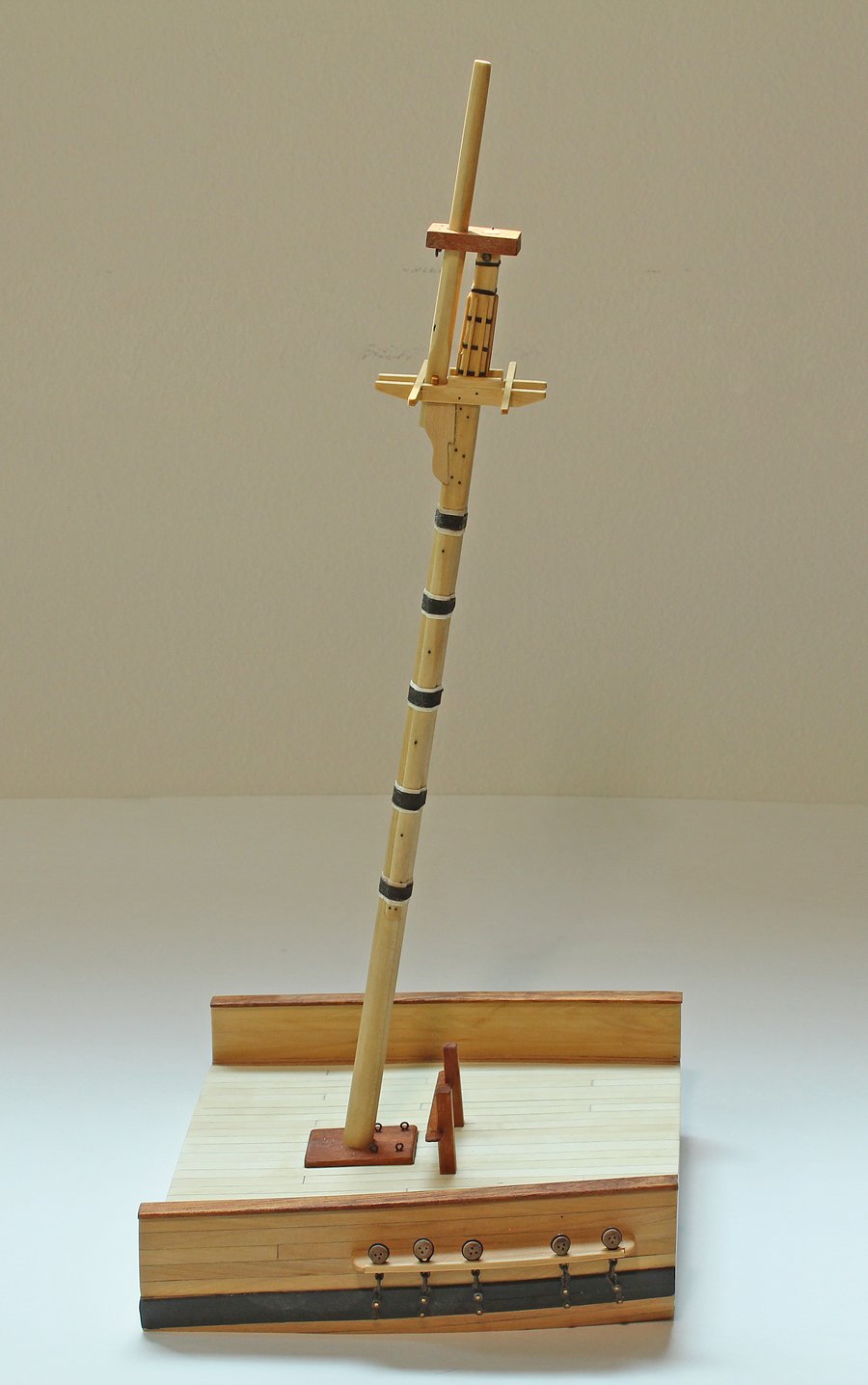
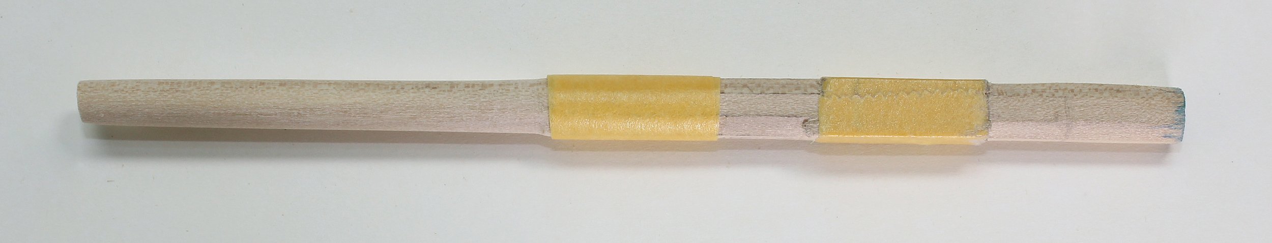
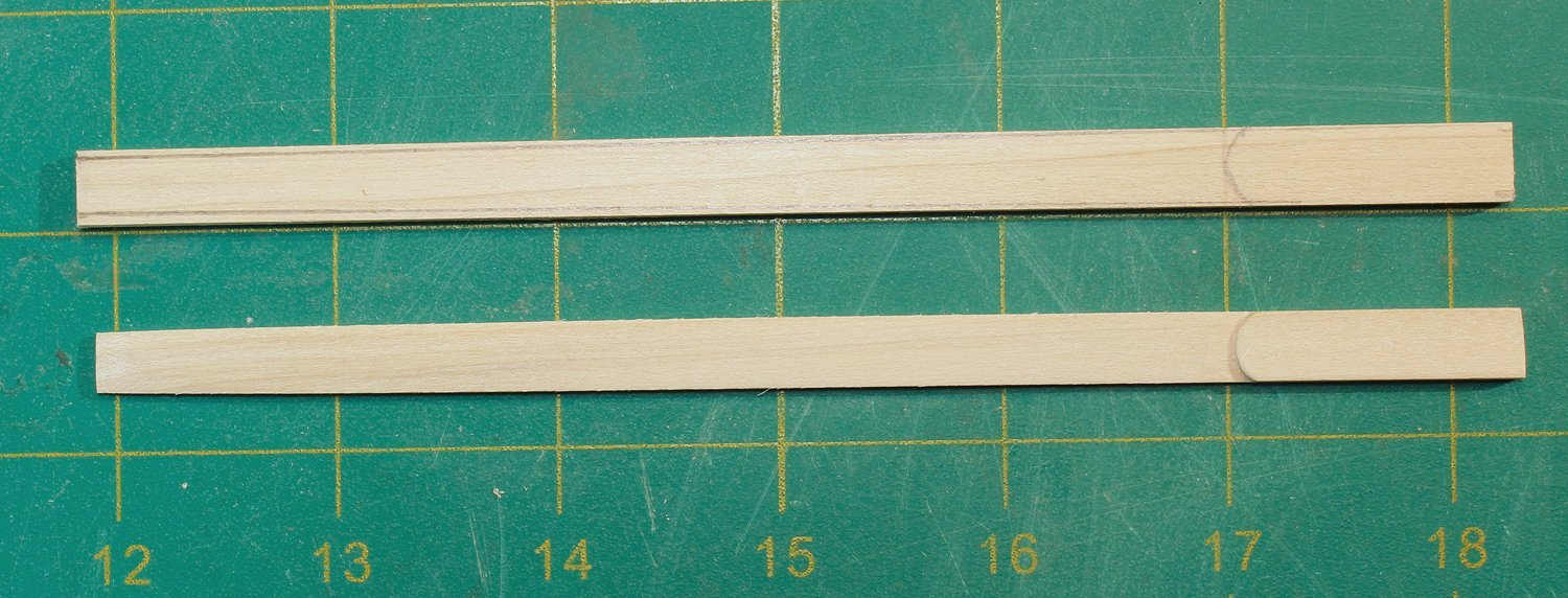
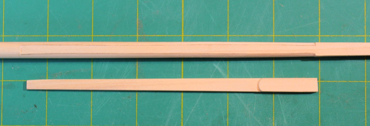
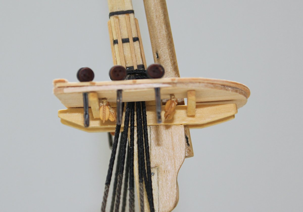
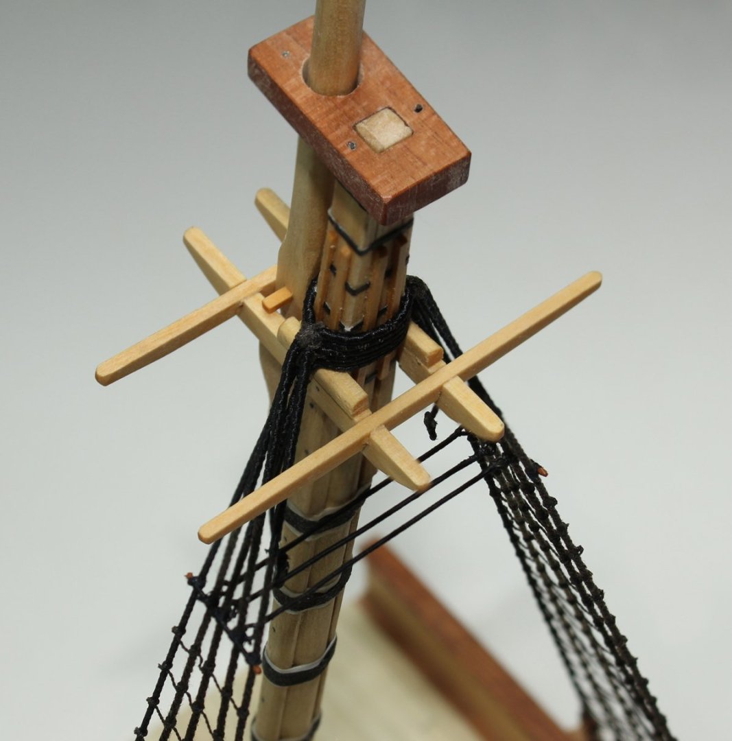
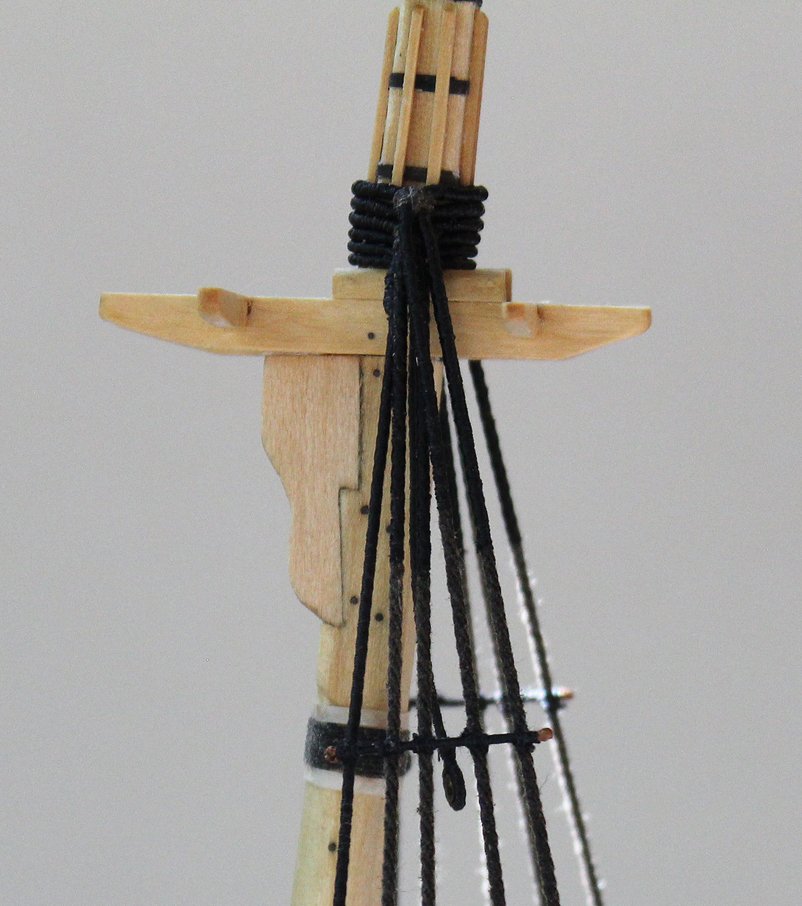
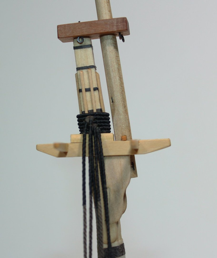
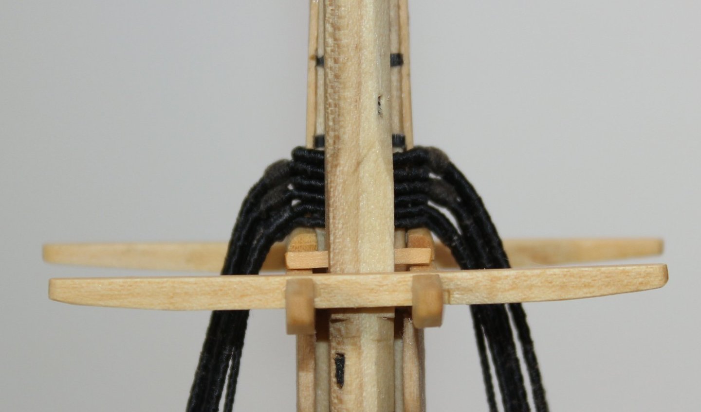
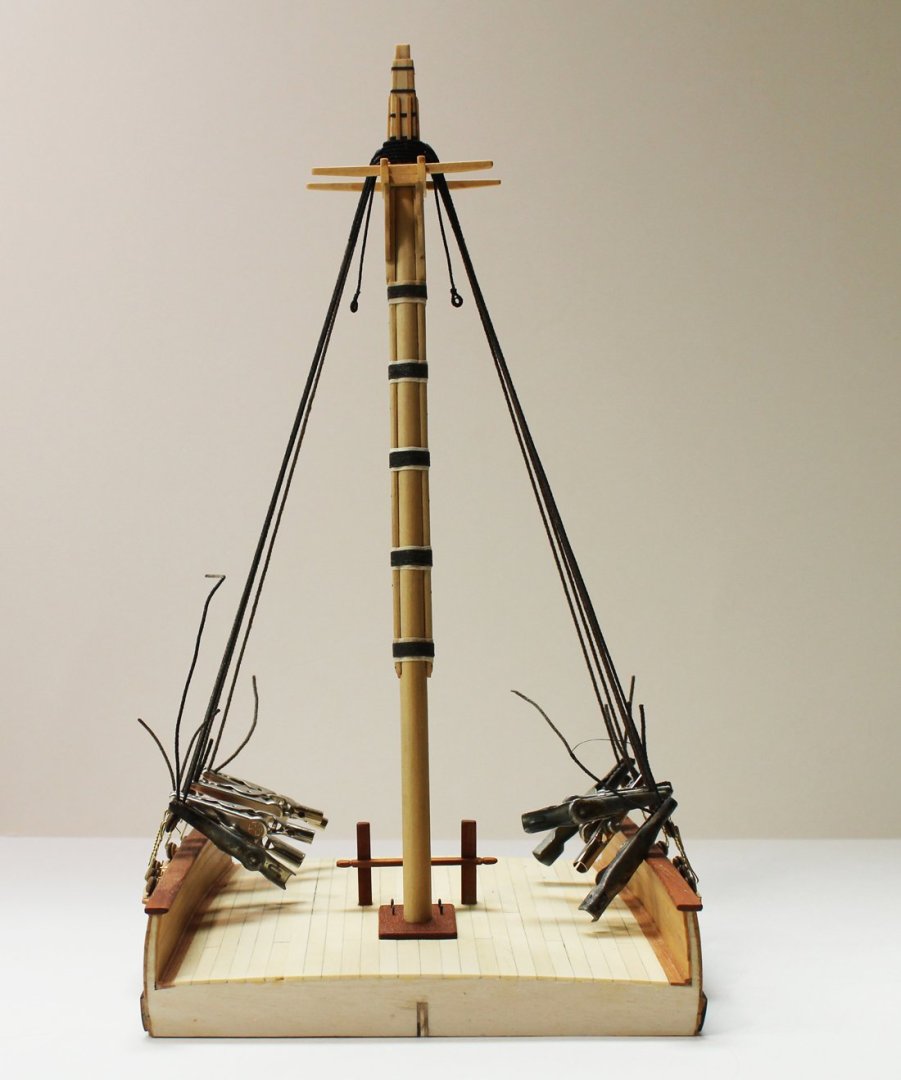
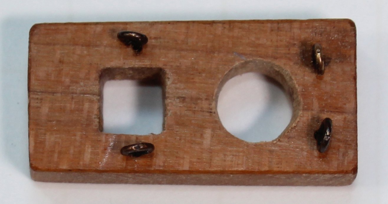
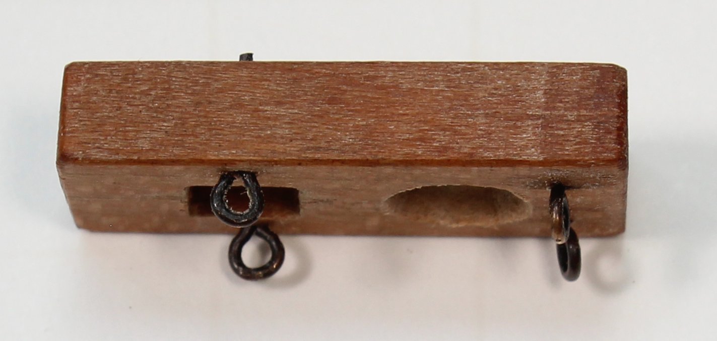
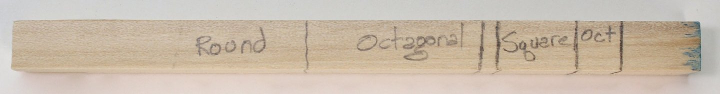
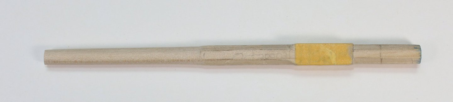
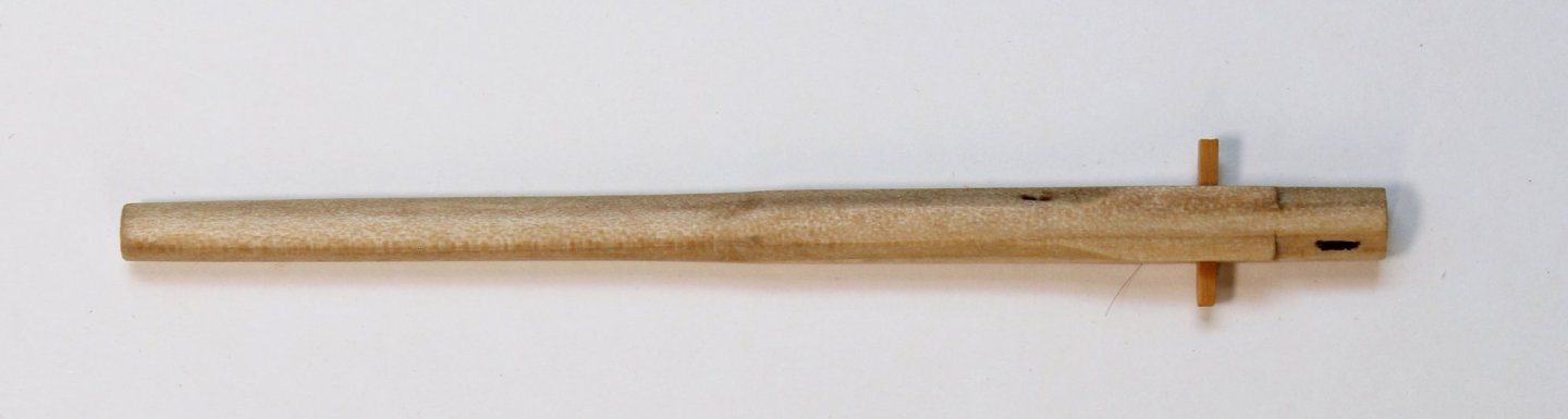
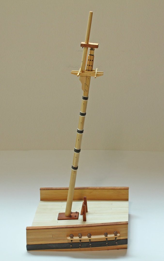
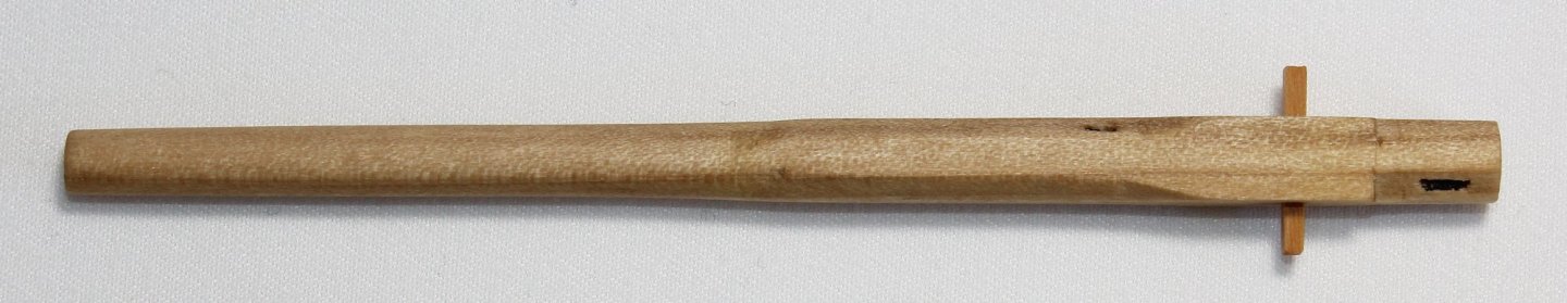
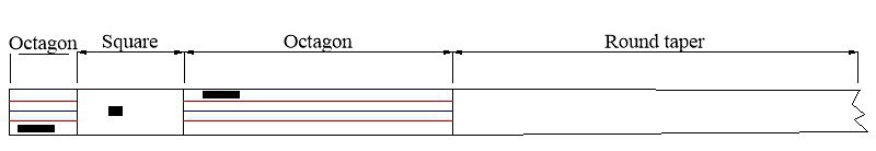
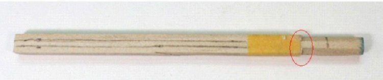
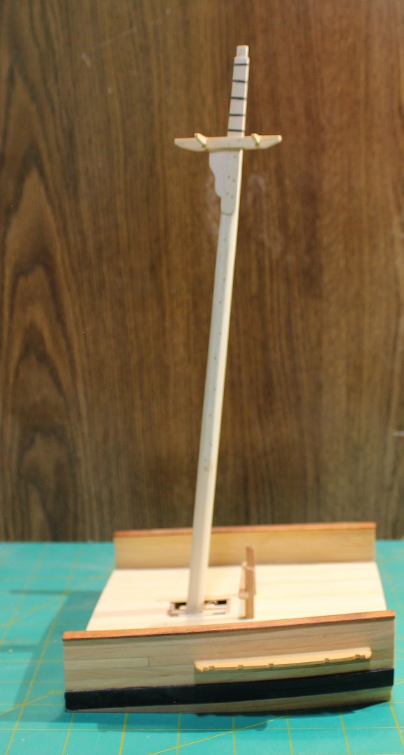
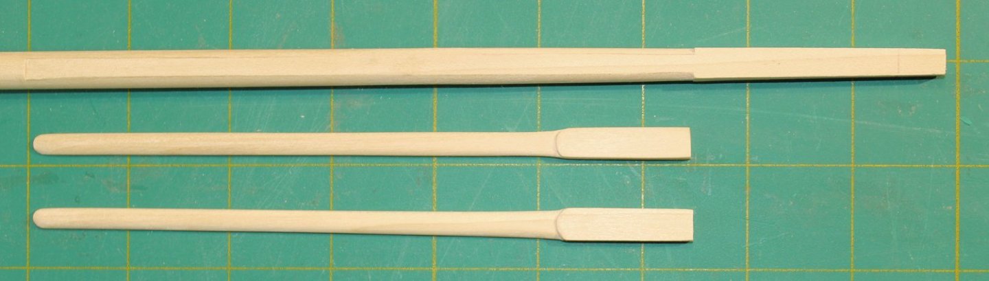
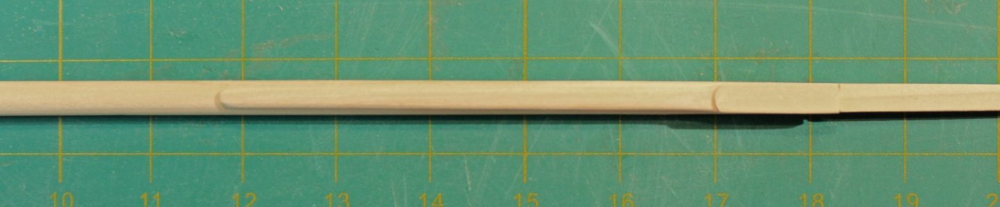
The mast cap has two openings: a round one for the topmast and a square one for the lower mast head. There are four eyebolts that extend all the way through the mast cap. I raided my scrap box for a contrasting color piece of wood. Both openings were made with a regular drill. The square opening was then shaped with a chisel and the round one was enlarged with sandpaper wrapped around a dowel. It will not be installed until much later. Although it also will not be installed for a while, I made the topmast next. The dimensions of the topmast are determined by the diameter of the lower mast. The lower end of topmast is 7/10 the diameter of the mast and the upper end is 11/20. This will be a stub topmast as the actual length of this mast would be 8” on the model. Its shape is more complicated than the lower mast. The lowest section (the block) is octagonal, the next section is (the heel) square, followed by another octagonal section. The upper part of the topmast is round, tapering as it goes to the head. There are three openings in the mast; the middle one is for the fid (the rectangular peg which prevents the mast from falling between the trestle trees) and the other two are for sheaves. The kit will contain a template for the topmast. Starting with a ¼” square dowel, I marked out the mast for the various transition points. Using the 7:10:7 ratio for determining the corners of the octagon, I drew the lines for those two sections. The mast taper begins at the end of the upper octagon. The blue line is the centerline and the red lines are the corners of the octagons. Just as was done for the main mast, I taped off the square section to protect it from errant chisel cuts. The pictures shows a completed topmast above a square dowel. There is extra wood on the top and bottom of the dowel for ease of handling. I used a saw to cut a shallow groove between the octagonal and square areas on the corners of the square section (circled area). This transition should stay sharp. The lower octagonal section was shaped with a sanding stick. The upper octagon and round area were both shaped as octagons, without any taper. Another piece of tape was used to protect the upper octagon and the upper part of the mast was rounded and tapered. After removing the tape, the transition between the octagonal and round sections and between the square and upper octagonal sections were smoothed. Making the holes for two sheaves and the fid was next. The upper and lower sheave openings are in the octagonal sections and are 90 degrees to each other and 45 degrees to the fid hole. The dimensions for the fid opening are one-third the mast diameter high and one-quarter the mast diameter wide, in this case 3” x 2.5”. The opening was formed from multiple drill holes, squared off with a #11 blade. The fid was made slightly smaller than the size of the opening and long enough to span the trestle trees. The sheave openings are 8” long and 1.5” wide. I simulated the sheaves on this model. These were trickier to drill accurately because they are on angled faces. Here is how I made them. The sheave opening was marked on both sides of the mast. I put the mast in a vise, clamping it in the upper octagonal area, just above the sheave opening. A small hole was drilled near the top and bottom of the sheave opening but I did not drill completely through the mast. The mast was repositioned in the vise and the holes on the other side were drilled. The holes on each side were enlarged to the correct width of the opening. I did this slowly, working a little bit on one side and then switching to the other side. The holes eventually met. Then, using a #11 blade, a shallow groove representing the sheave was formed between the two holes and the “sheave” was painted. The final step was to cut off the excess wood at the top and bottom of the topmast and apply a finish. This is how it looked installed.


- 80 replies
-
- 30
-
-
-
- rigging/masts
- NRG
- (and 2 more)
-
Or go to the NRG store. https://thenrgstore.org/collections/the-nautical-research-journal
-
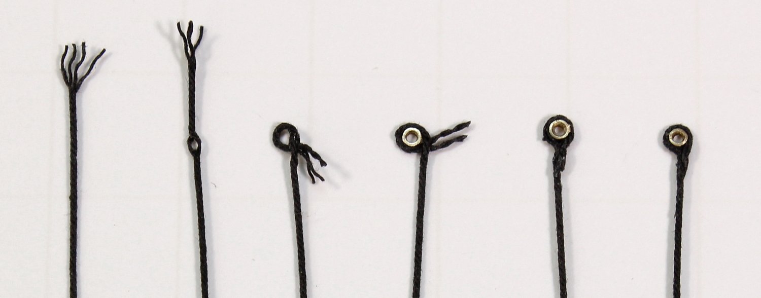
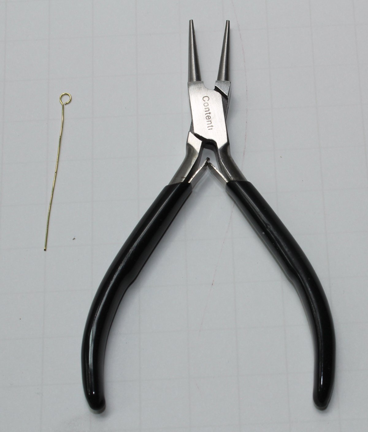
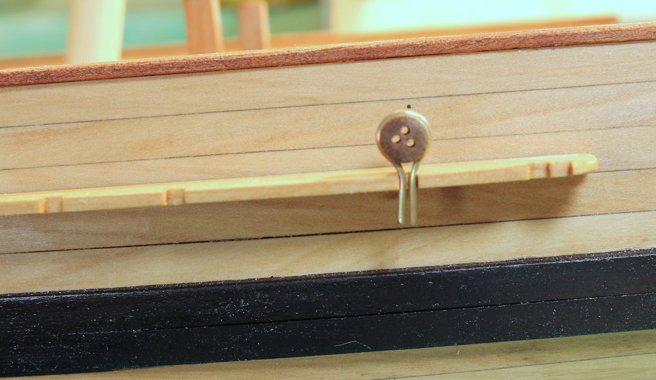
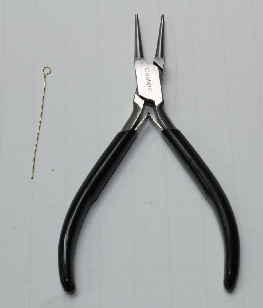
Most rings and eyebolts provided in kits are oversized, especially at the smaller scales. They are very easy to make. To make rings, temper (soften) brass or copper wire of the appropriate gauge by heating it in a flame. I use my gas cooktop. Let it cool slowly. Drill a hole larger than the wire in one end of a dowel that is slightly larger than the desired inside diameter of the ring. Thread the wire through the hole and tightly wrap the wire around the dowel. When you are finished, tape one side of the wire. This will help prevent the rings from flying away when you cut them from the dowel. Use a metal cutting saw to cut through the wire. If you don’t own the Czech-made JLC saw, get one. They are fantastic. No monetary interest in the company, so here is the link to their website. https://www.umm-usa.com/catalog/tools_JLC.html The pirated cheap imitations on Amazon are not the same quality. Gently bend the wire to close the gap left by the saw kerf. Clean and blacken. Easy! For rings that are going to be under a lot of tension, solder the ring closed before blackening. If you are making a lot of rings, you can chuck the dowel into a drill rather than hand wrapping it. Eyebolts are just as easy to make but you will need fine-tipped round-nosed pliers. Your best source for this tool is a jewelry supply store. Mark on your pliers the desired inner diameter of the eyebolt. Take a length of wire and file the end flat with a metal file. Grasp the wire between the jaws of the pliers without any wire protruding beyond the jaws and wrap it around one of the jaws until you have a complete loop. Sharply bend the wire back towards you to form the stem. Cut to length, clean, blacken and repeat.

- 80 replies
-
- 13
-
-
- rigging/masts
- NRG
- (and 2 more)
-
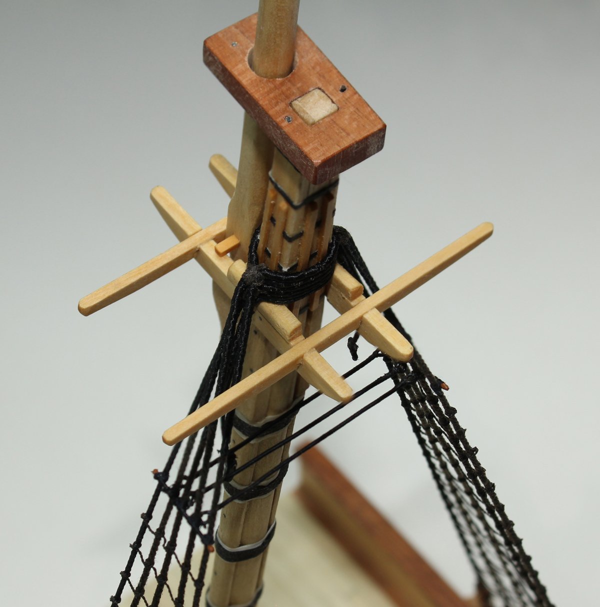
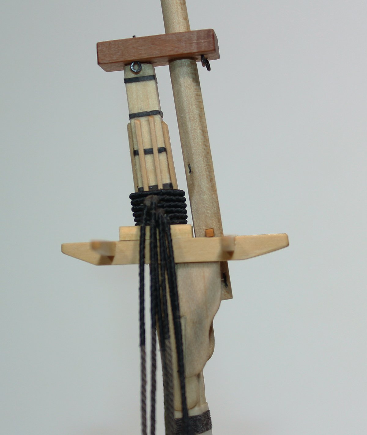
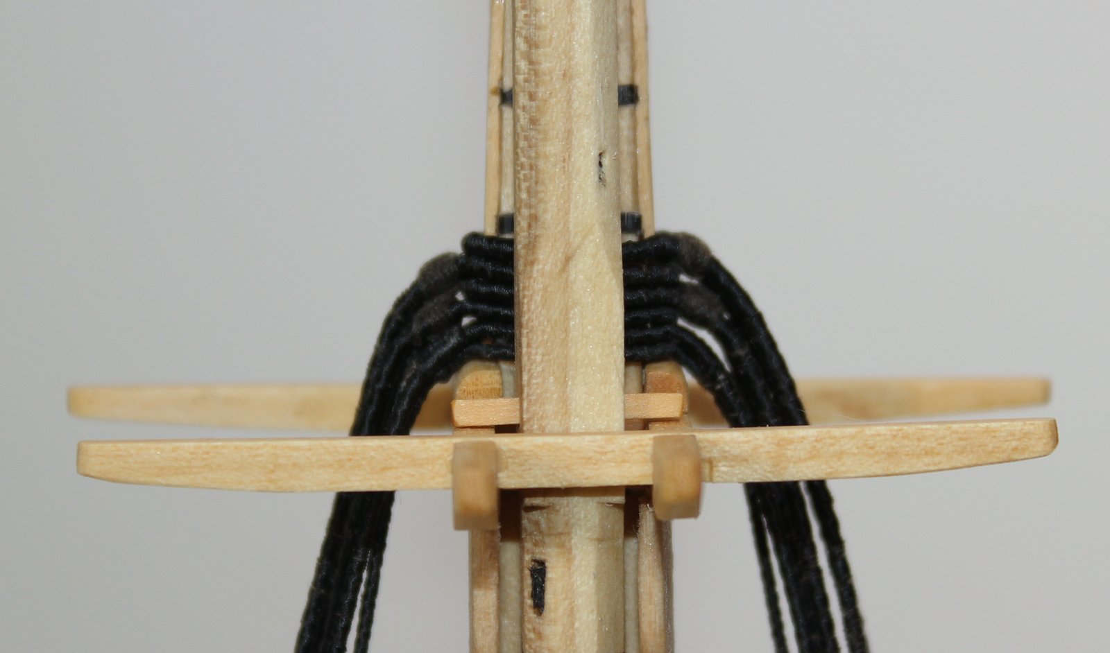
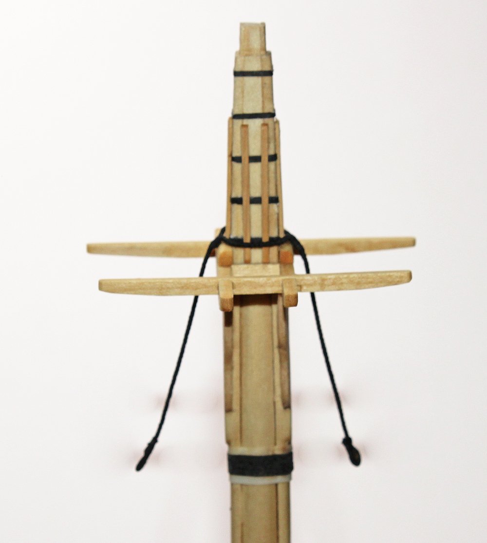
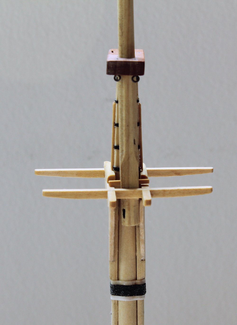
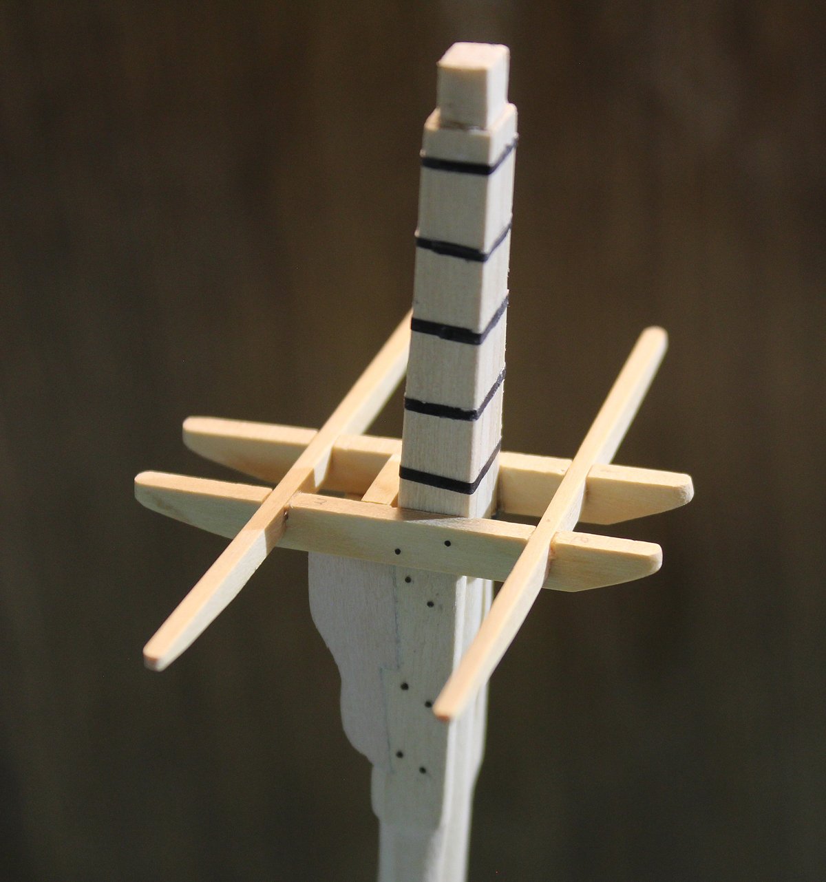
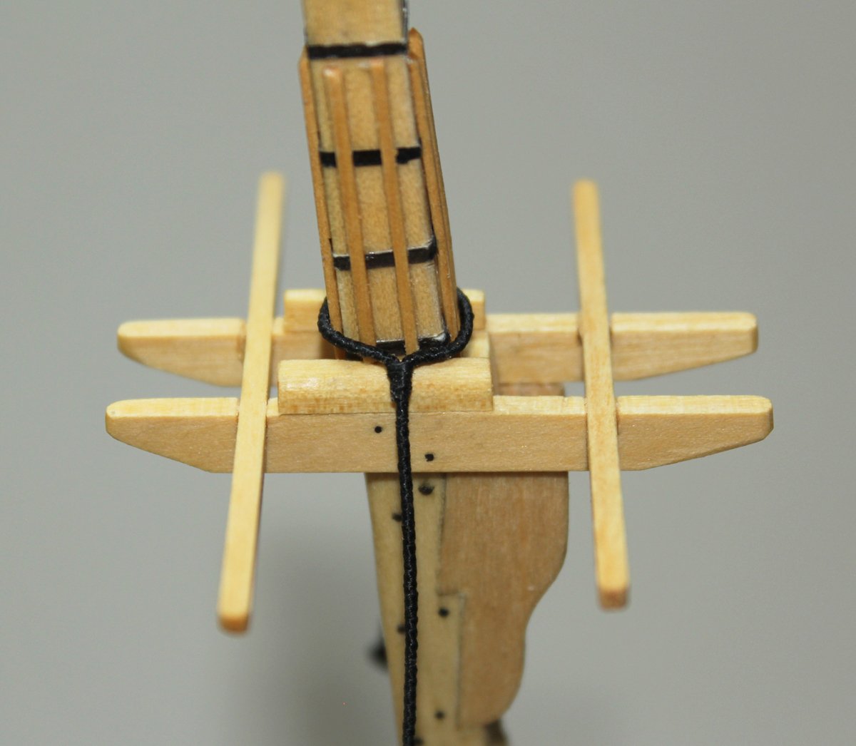
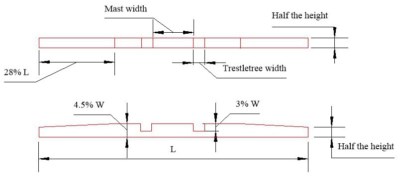
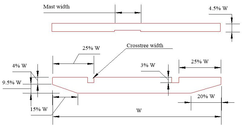
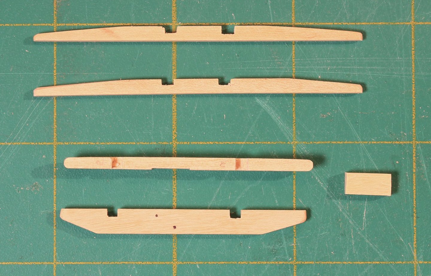
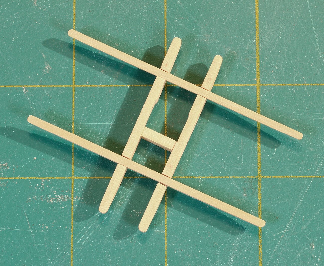
The dimensions of the top are determined by the size of the topmast; the dimensions of the trestle and cross trees are derived from the size of the top. The topmast on this ship was specified on the plans as 32’ 10”. The width of the top is 1/3 the length of the topmast wide and ¾ the top’s width fore-to-aft. The hole in the top is 5/12 the width of the top. The kit will provide a template for the top. The trestle trees run fore and aft; the cross trees run across the ship. The trestle trees are as long as the top. The cross trees are different lengths; the fore cross tree is shorter than the aft one because of the curvature of the top. Look at the following drawings. The dimensions of the trestle and cross trees are derived from the width of the top (W). There is a small notch on the inside face of the trestle tree for the mast head. I made them from 1/8” basswood sheet and sanded them down to the correct thickness. It is important to make sure that the top surface of the assembly is not twisted. The easiest way to avoid twisting is to turn it upside down and put a weight on top of it while the glue dries. Trestle Tree The small piece of wood between the cross trees is called the chock. It is a spacer between the mast head and the topmast. It is the same height and width as the trestle tree. I inserted the mast into the hole in the deck. As mentioned previously, the trestle trees are horizontal to the water line. The cross/trestle tree assembly was placed onto the bibs and the angle of the top of the bibs was adjusted with a sanding stick until the trestle trees were horizontal. They were glued to the bibs. The final pieces to install onto the trestle tree are the bolsters. These are quarter-round pieces of wood that prevent the shrouds from rubbing against the trestle trees. They are slightly wider than the trestle tree and one-third its height. Because the shrouds extend aft from the mast, the bolster starts at the fore end of the mast head and extends back to the aft cross tree. I have added bolts to the trestle trees using 24 g copper wire. Just as the bolsters protect the trestle trees, battens protect the mast head. There are two battens on each side of the masthead and end below the second hoop from the top. In order to lay flat against the mast head, small grooves were cut into the undersurface of each batten where it crossed a hoop with a #11 blade.

- 80 replies
-
- 22
-
-
-
- rigging/masts
- NRG
- (and 2 more)
-
Use of “other power tools”
tlevine replied to kgstakes's topic in Modeling tools and Workshop Equipment
I used a Cricut once to attempt to cut planks from 1/16" boxwood. There was not need for a second attempt. It worked fine on basswood. -
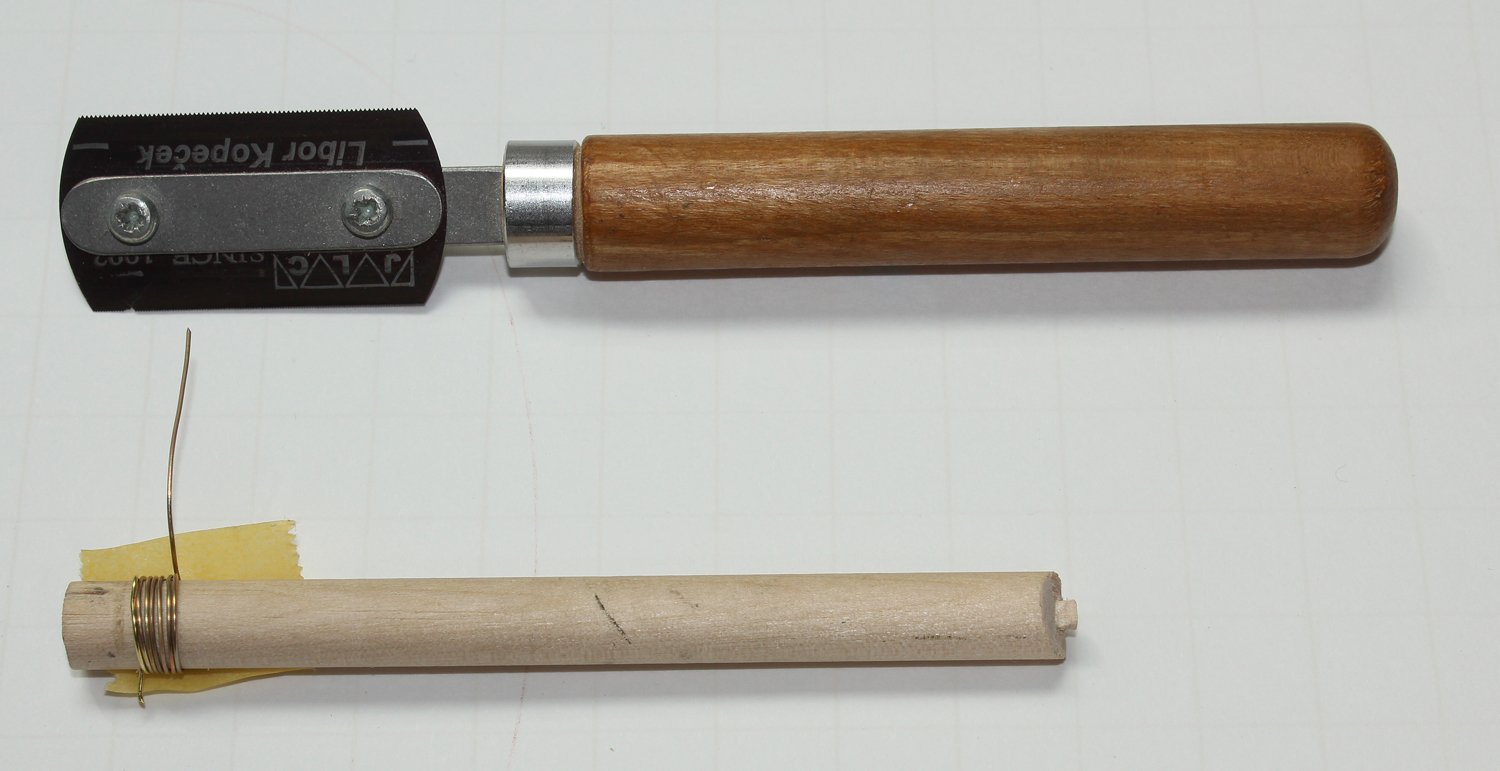
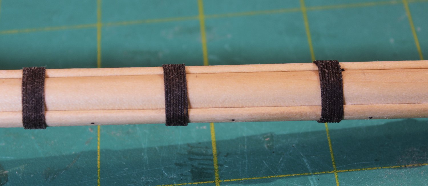
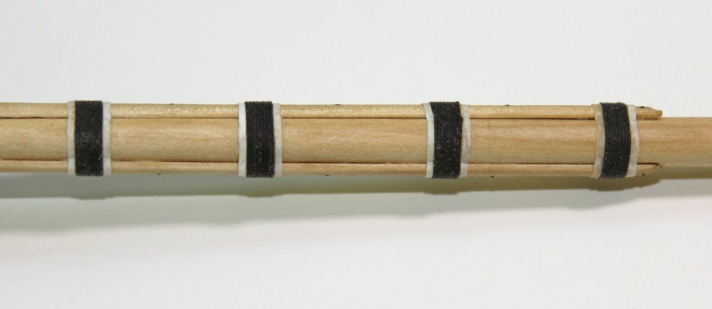
Time to build up the port and starboard sides of the mast head. I used the mast template to determine the dimensions. A real mast would have its top cut at an angle to lock it into the mast cap. This detail is not visible so I shaped it as a simple square. The full- sized dimensions are 9” square by 11”tall, which is the thickness of the mast cap. Iron bands were placed around the mast head at regular intervals. I used paper dyed with archival ink. On this photo you can see that I have added bolts to the cheek. The bolts are made from 24 g copper wire patinated with liver of sulfur. The wooldings provide extra strength to the mast. The number and composition varied based on the era. At this time, they were made of 2.5” tarred rope (all rope dimensions are circumference). Because I will be using several diameters of line in the build, I made a table consisting of the full-sized circumference, the circumference at 1:48 scale and the diameter at 1:48 scale. The easiest way to determine the diameter of your rope is to wrap 10-20 windings around a dowel, measure the distance and divide it by the number of windings. Remember, circumference is πd so the rope diameter is circumference/π. I used eight wraps for each woolding. To hide the ends of the wooldings, I tucked them in the gap between the mast and the cheeks. Above and below the wooldings are wooden hoops. I simulated them by cutting strips of paper and wrapping two layers around the mast. This gave the hoops the appropriate thickness.

- 80 replies
-
- 27
-
-
- rigging/masts
- NRG
- (and 2 more)
-
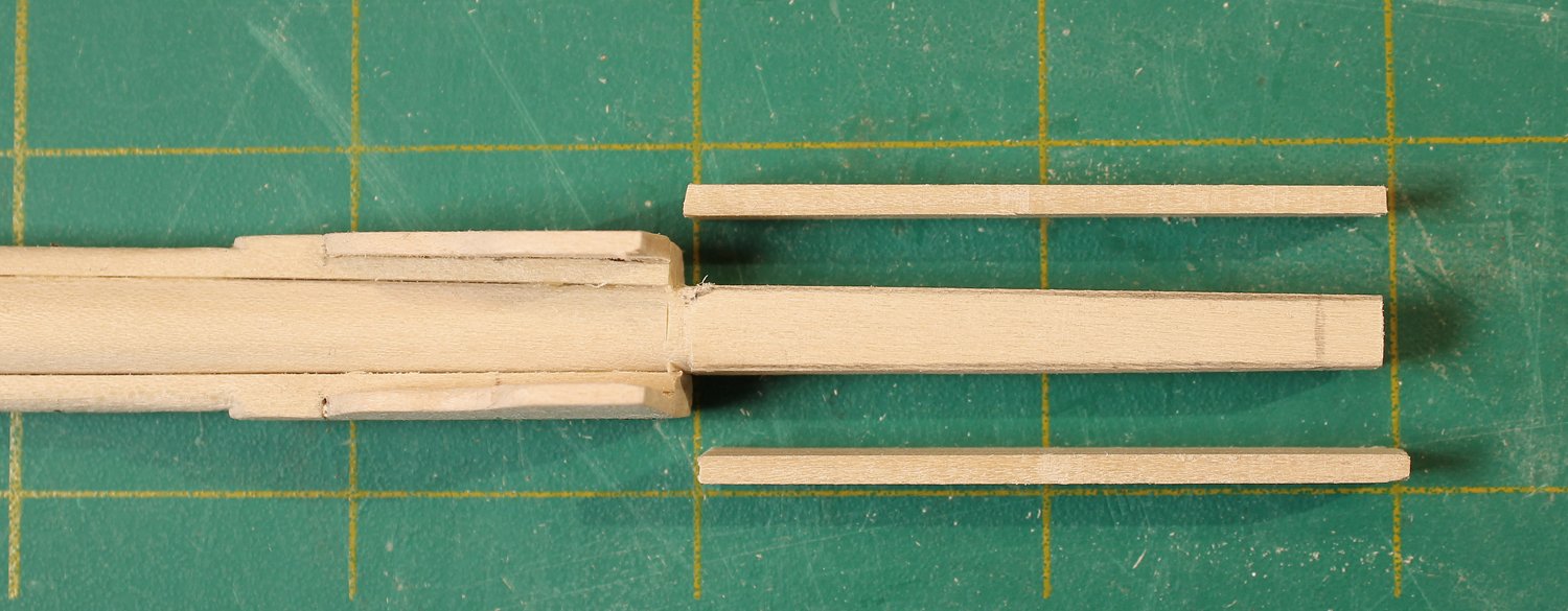
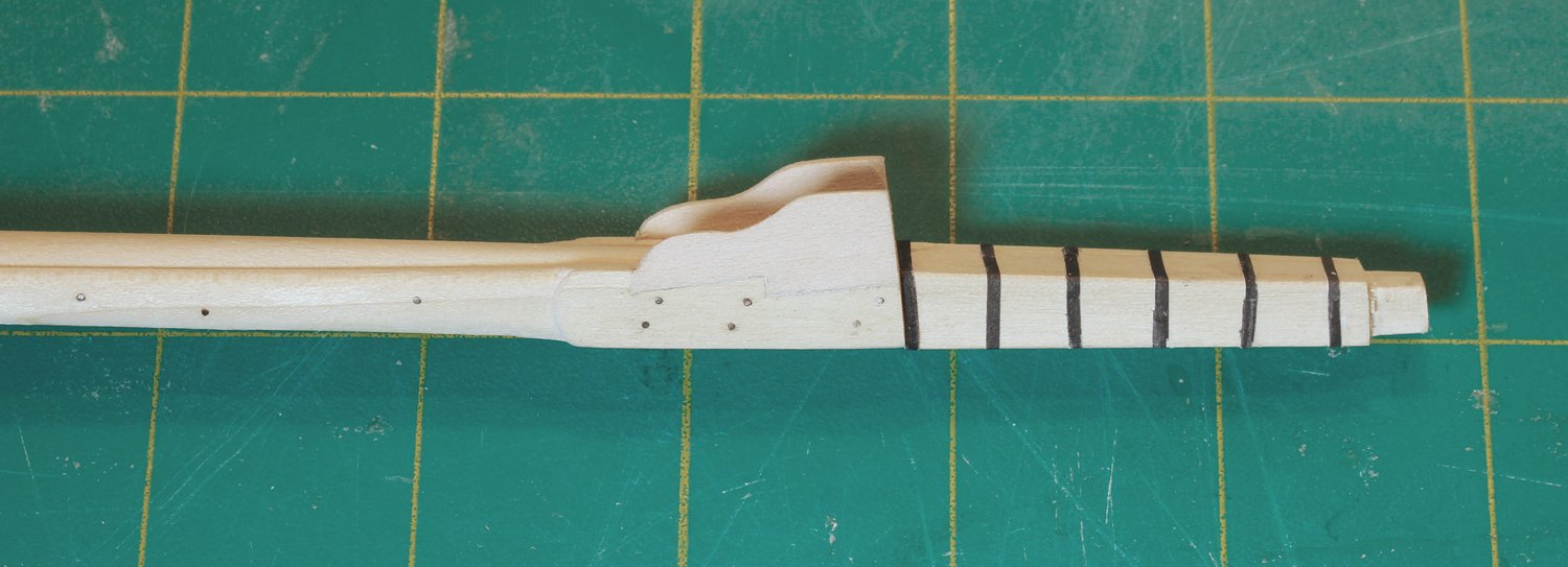
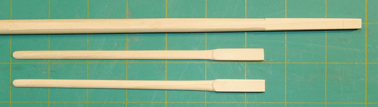
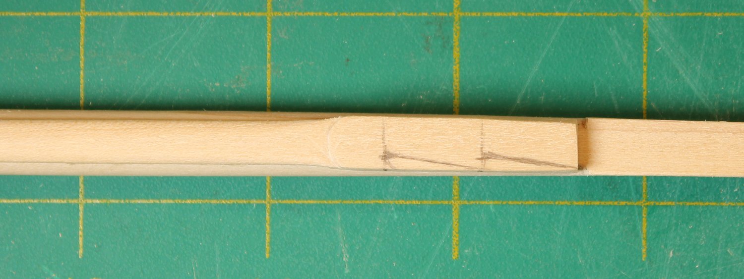
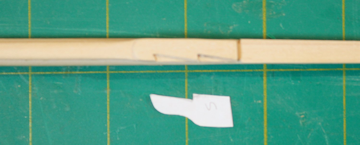
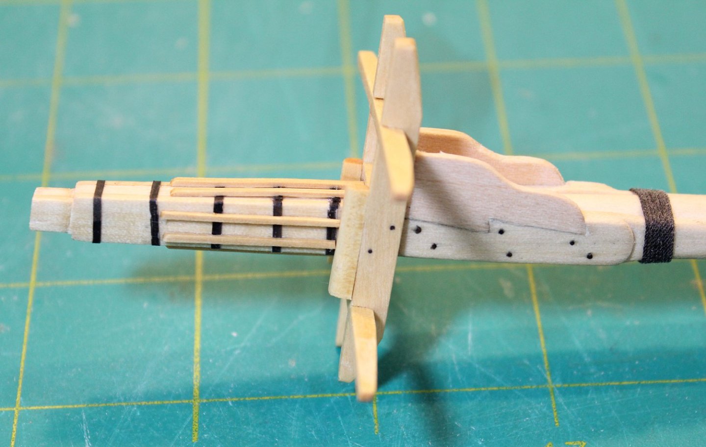
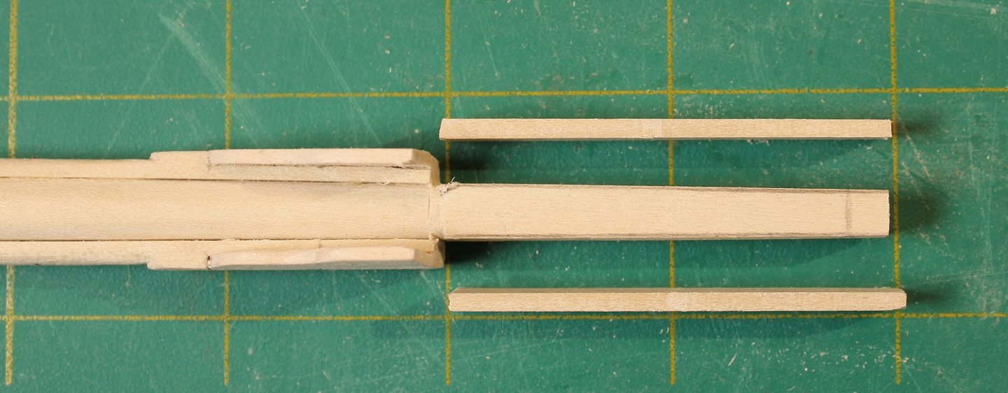
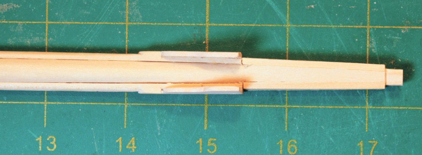
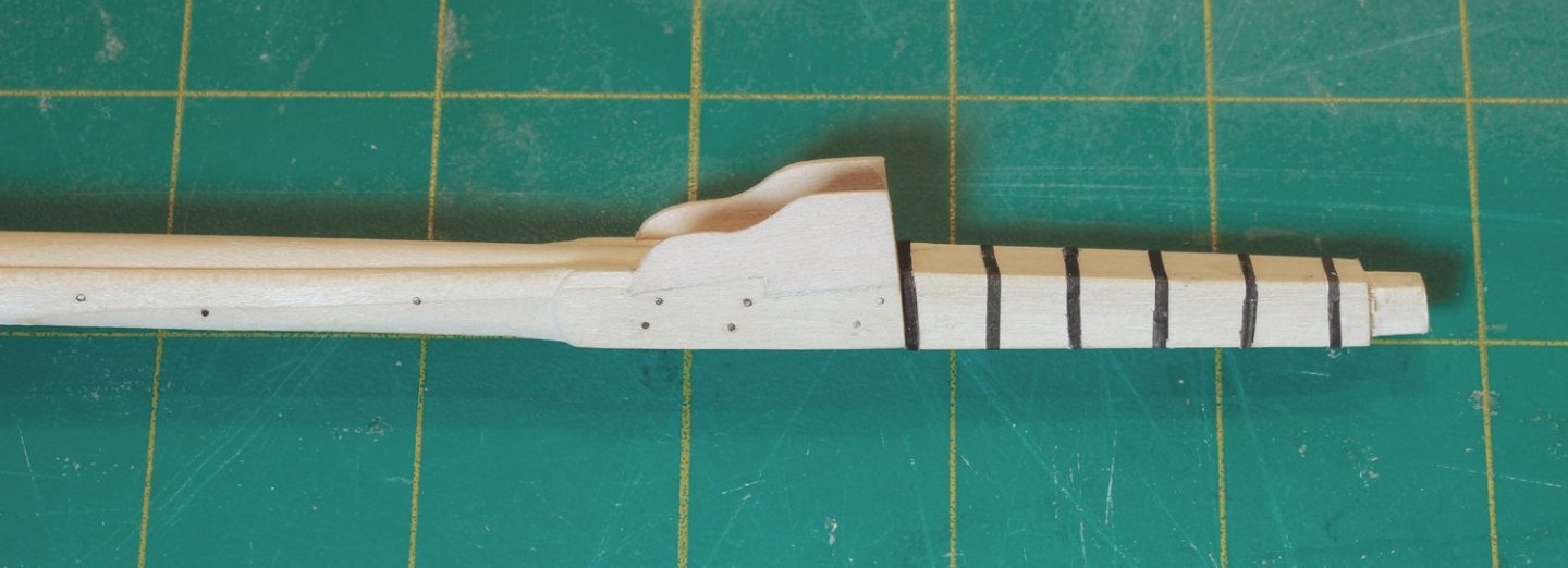
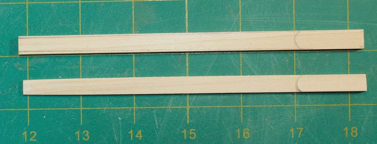
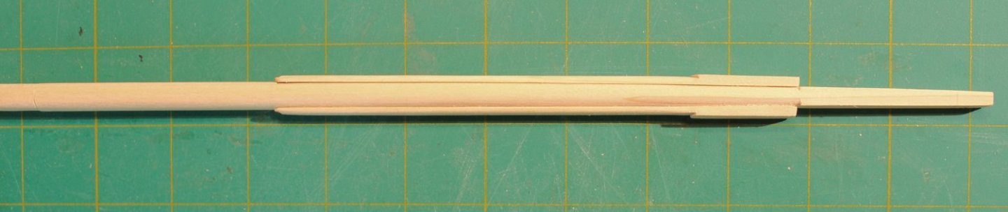
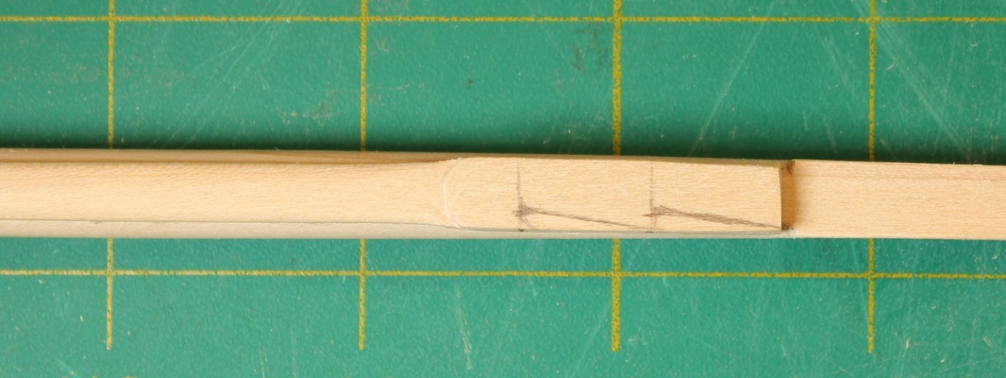
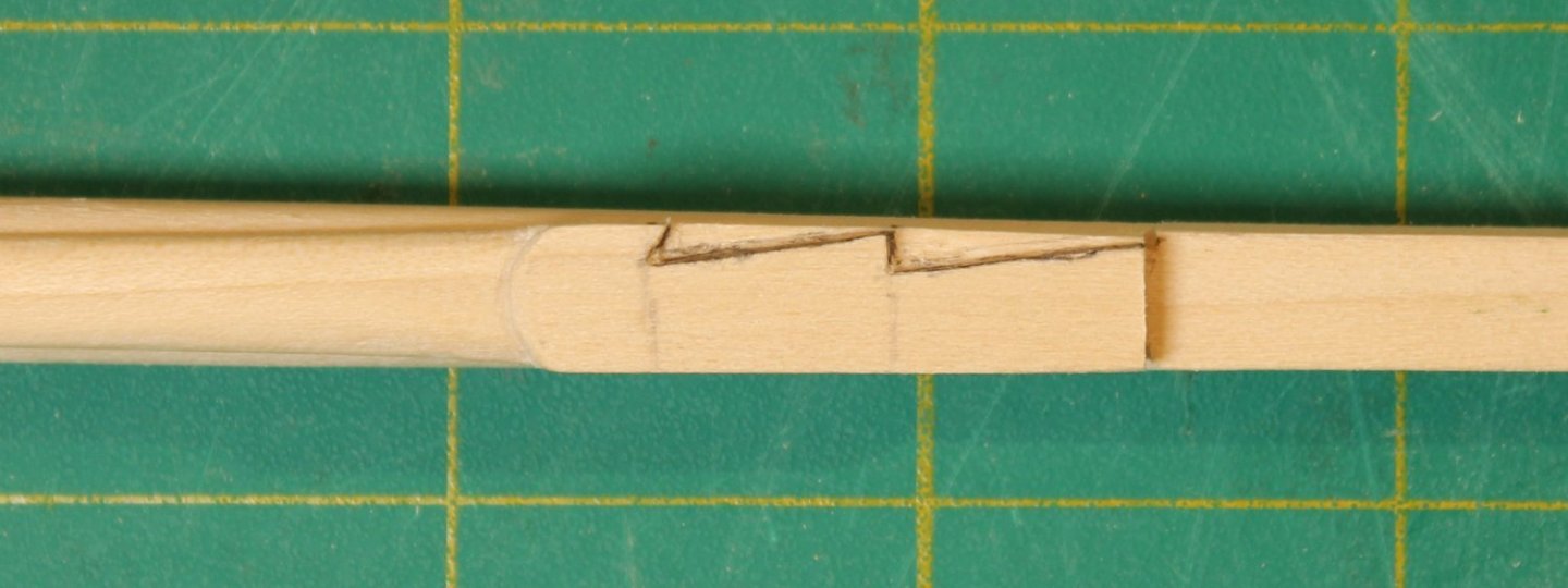
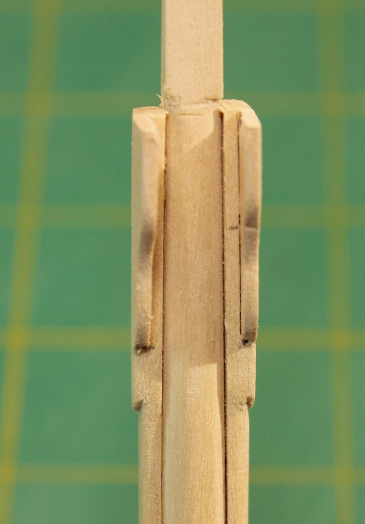
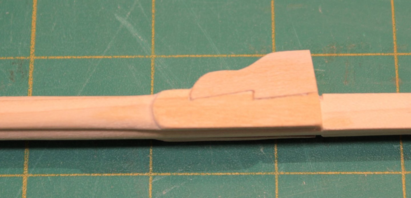
The cheeks are located on either side of the mast. Their inner surface is flat so the sides of the mast will need to be flattened. On this ship they are 25 feet long and extend from the bottom of the mast head to approximately 12 feet above the deck. At this scale, that is 6.25” long, ending 3” above the deck. A template is included in the practicum. The upper part of the cheek is called the hounds and is thicker than the rest of the cheek. The photo shows the cheek before and after shaping. The outline of the cheek was drawn onto both sides of the mast. This outline marks where the mast needs to be flattened. The hounds remain flat but the rest of the cheeks were rounded over. The apparent concavity in these cheeks below the hounds is an optical illusion. 0 The cheeks were then glued to the mast. Look at the straight line extending up the mast on the side view and the step-off above the hounds fore and aft. The next step was to make and install the bibs. These are forward extensions of the hounds and their purpose is to support the trestle trees. They are the same thickness as the hounds and are attached with a morticed scarf joint for strength. This is how I made the mortice. Start by drawing the zig-zag mortice onto the hound. It extends approximately three-quarters of the length of the hounds. Because the lower end of the bib is curved, the bottom mortice cut is also curved. Since I was using basswood, I used a #11 blade to inscribe the mortice. I did this a few times, deepening the cut with each pass. Once I was halfway through the hound, I used a chisel to remove the wood from the mortice. I have used pencil to make the joint more visible for you. This joint would not have been caulked and so the joint would not be very visible. It is important to keep the sides symmetric. Next, I drew the bibs on paper. The top of the bibs is 3/8” wide and it is half the thickness of the cheek. I laid the paper over the hounds and made a pencil rubbing of the mortice to get the shape of the tenon. Each side will be slightly different so two templates were needed. The one below is marked “S” for the starboard side. The front edge of the bibs was rounded over and installed; the top edge was left flat. There is a forward angulation to the bibs to allow the trestle trees to rest on them parallel to the water line. The top edge of the hounds and bibs should form a straight line.


- 80 replies
-
- 28
-
-
-
- rigging/masts
- NRG
- (and 2 more)