

tlevine
-
Posts
2,033 -
Joined
-
Last visited
Content Type
Profiles
Forums
Gallery
Events
Everything posted by tlevine
-
 I was great getting together with everyone, not to mention learning from a master. Hone your chisels!
 -
Chisel hone guide question
tlevine replied to CPDDET's topic in Modeling tools and Workshop Equipment
Take a look at this from the Carving Glove Guy. I have used this to sharpen my microchisels for several years. https://thecarvinggloveguy.com/image_preview.html?img=TCGG-DYSTROPKT -
Making a template like John said is the easiest thing to do. Cut the outboard line and, using a compass or divider, draw the inboard line. Sheet basswood 1/16" is easily cut with a #11 blade.
-
Looking good. Half the battle is understanding the process, the other half is accomplishing it!
-
Kevin, it is much easier to use a Dremel than the lathe. I think your biggest problem is the disc. It is much too thick. Greg Herbert told me about these; their original use was in a dental lab. They are brittle, so wear glasses when you are using them. I can typically get three molding from each disc.
-
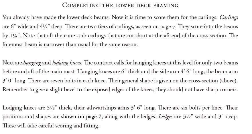
Have you looked at this? Page 12. http://www.admiraltymodels.com/Echo_Xsec_Fitting_Out.pdf
-
Nicely done.
-
That joinery looks incredible.
-
It's crazy how some of the simplest appearing parts can cause the most trouble. And, yes, the mast step is completely hidden inside the pump well.
-
The NRG website is currently experiencing technical problems. Many who try to log in are getting "Privacy error" or similar messages. The website is secure. If you wish to go to the website, type in the entire URL, https://www.thenrg.org, rather than simply "thenrg.org".
-
- 4
-

-
Both as a member/moderator of MSW and in my official capacity as Chairman of the NRG, I want to give a big Thank you! to our administrative team, Jim and Chuck. As it was explained to me, this was a problem of not enough electricity to power some the servers and power outages to our data center server. Thousands of sites were affected. Also having lost a build log after the Big Crash, I am grateful that nothing was lost. Thank you again, gentlemen.
- 24 replies
-
- 17
-
-

-
What horrible news. Hope your life returns to some semblance of normal before the year's end.
-
Love the fairing cap concept. Definitely something I will steal for my next build.
-
I have the same light as Greg. Love it. It has almost no weight, unlike the other light attachments I have tried.
-
Nice work!
-
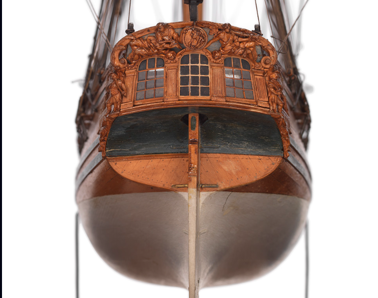
I like the side friezes but the counter looks (to my eye) too fussy. Even though the model needs cleaning, there appears to be a lighter color extending all the way across the counter.
-
Bend cast metal parts
tlevine replied to bogeygolpher's topic in Metal Work, Soldering and Metal Fittings
How brittle is the metal? Have you tried placing the pieces on a curved piece of wood (or even the side of a pot) and gently hammering in a curve with a rubber hammer? -
Since the structural strength is in your bulkheads, even balsa would work. It isn't necessary to fill in the entire space between the bulkheads. If you can pick up some pine from one of the big box stores, that would work well.
-
Patience? What's that? Seriously, the tops look great.
-
At the scale you are working at (1:55), you will rarely need a drill bit larger than #72. I built Roter Lowe back in the early 80's. When friends come over, they are always drawn to the colorful decorations. Historical accuracy be dam**d.
-
Gluing on planks
tlevine replied to rudybob's topic in Building, Framing, Planking and plating a ships hull and deck
By only applying glue to a few bulkheads at a time, you almost eliminate the need for clamps. Hold it in place with your fingers for a few minutes and you are good to go. Apply the glue to the bulkhead with either a toothpick or a #11 Exacto blade. -
To a large extent, what type of magnification you employ is a matter of personal taste (and budget). It also depends on what your vision is and if you wear bifocals. I own an ancient Zeiss operating microscope which I brought home after closing my practice. It has all the magnification levels you could desire. But with any microscope, you need to remove your glasses and hold your eyes a certain distance from the oculars. I hate taking my glasses on and off and so rarely use it. Optivisors come in different magnifications. The lenses are interchangeable. But the higher the magnification, the closer you must be to the object. The nice thing about an Optivisor is that I can easily flip up the lens and still be able to see because I am wearing my glasses. Druxey is right about lighting. Not only does a headlight prevent you from appreciating how light and shadow will interplay in the finished piece, but it will make everything look two dimensional during the carving process. That is fine for certain applications, like microsurgery or dissecting a frog, but it really is a detriment when you are creating a 3-D object from a flat surface.