tlevine
-
Posts
2,033 -
Joined
-
Last visited
Content Type
Profiles
Forums
Gallery
Events
Everything posted by tlevine
-
 Looks sweet, Dan. You will eventually use that same sanding disc on the tops of the bulkheads.
 -
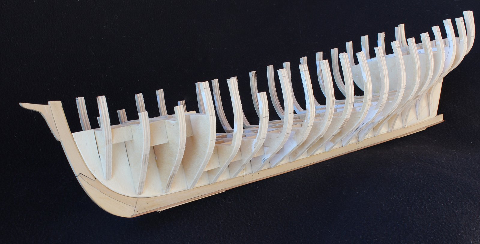
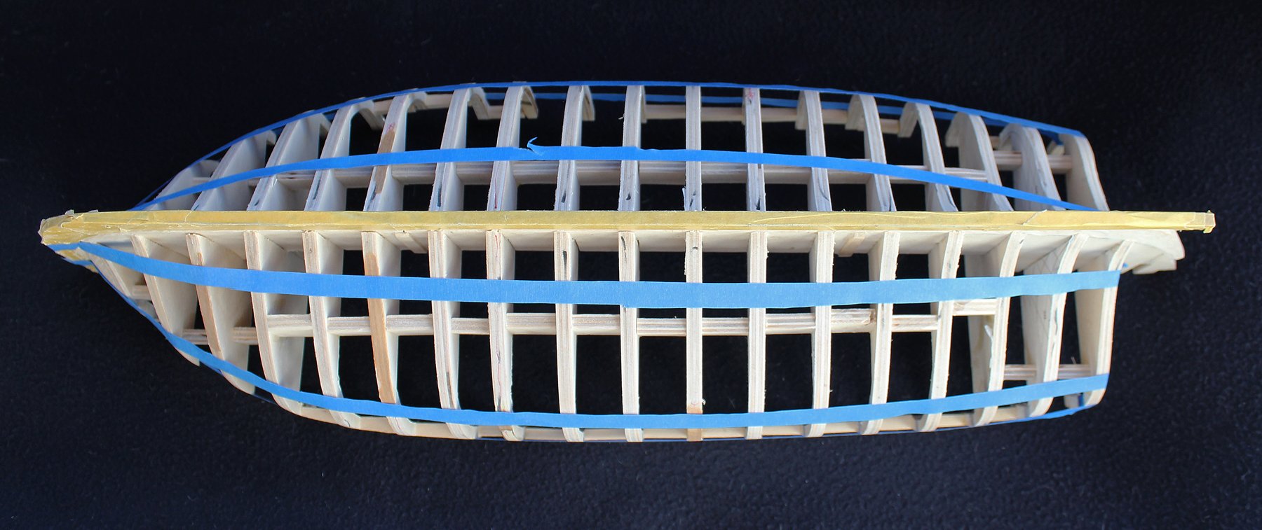
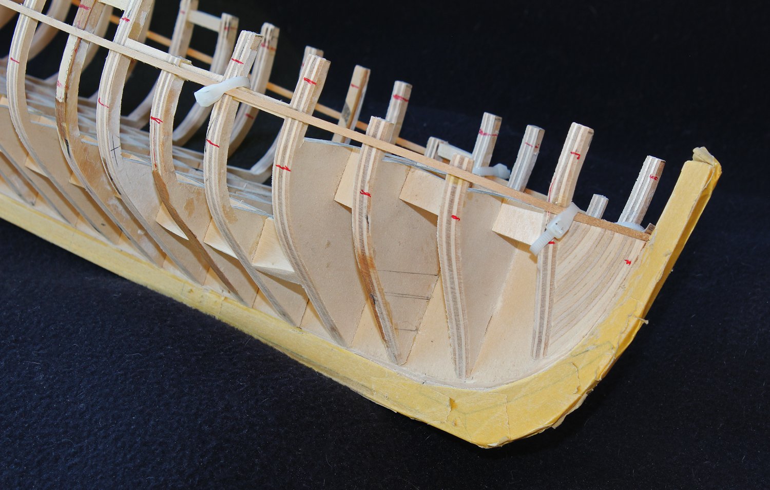
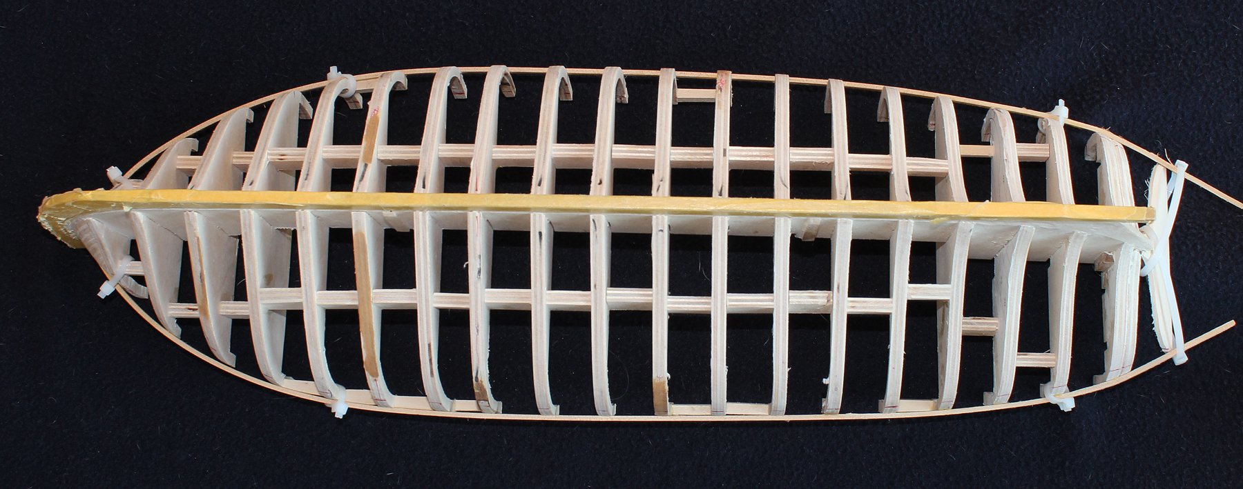
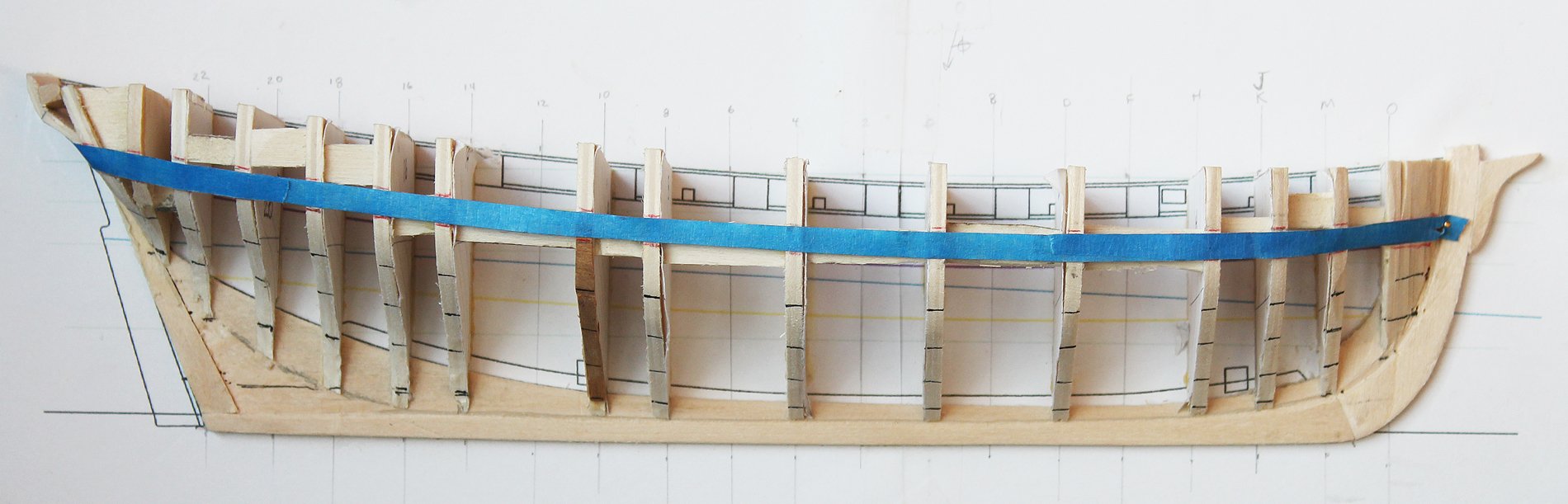
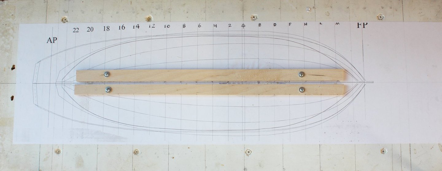
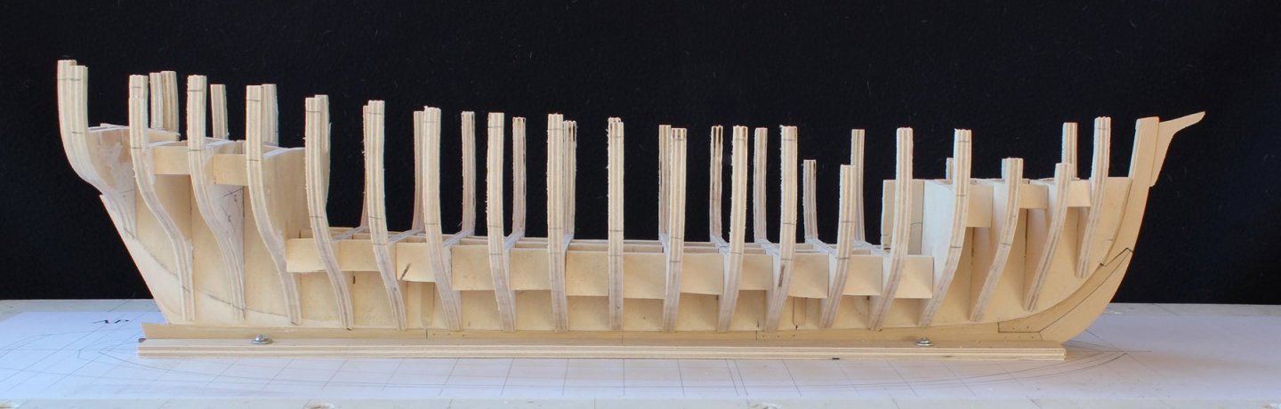
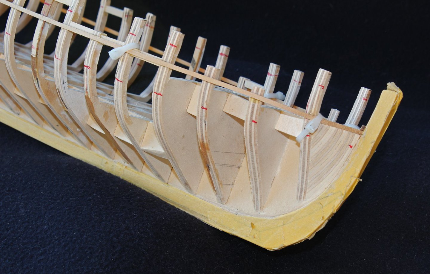
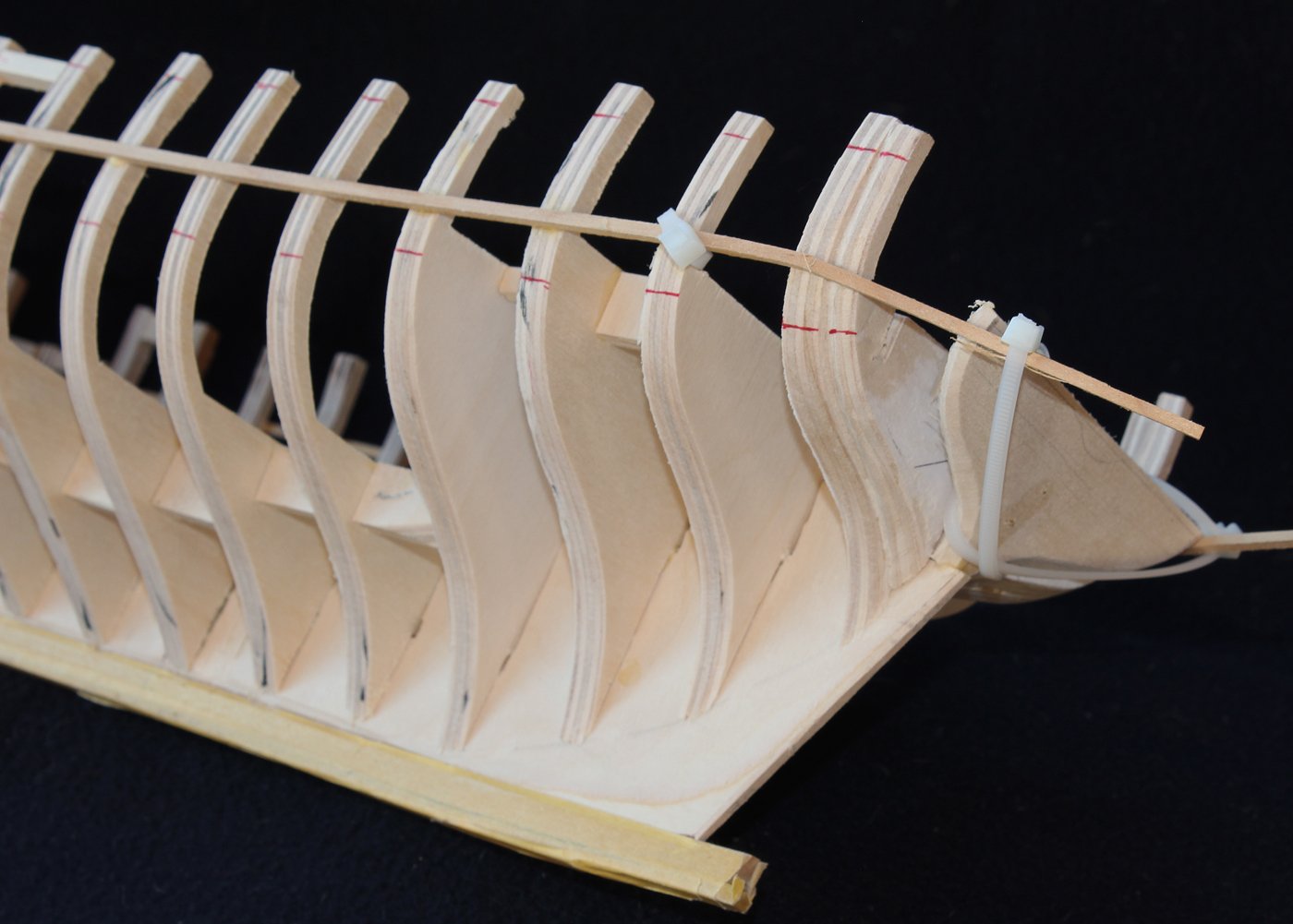
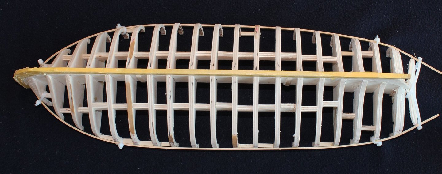
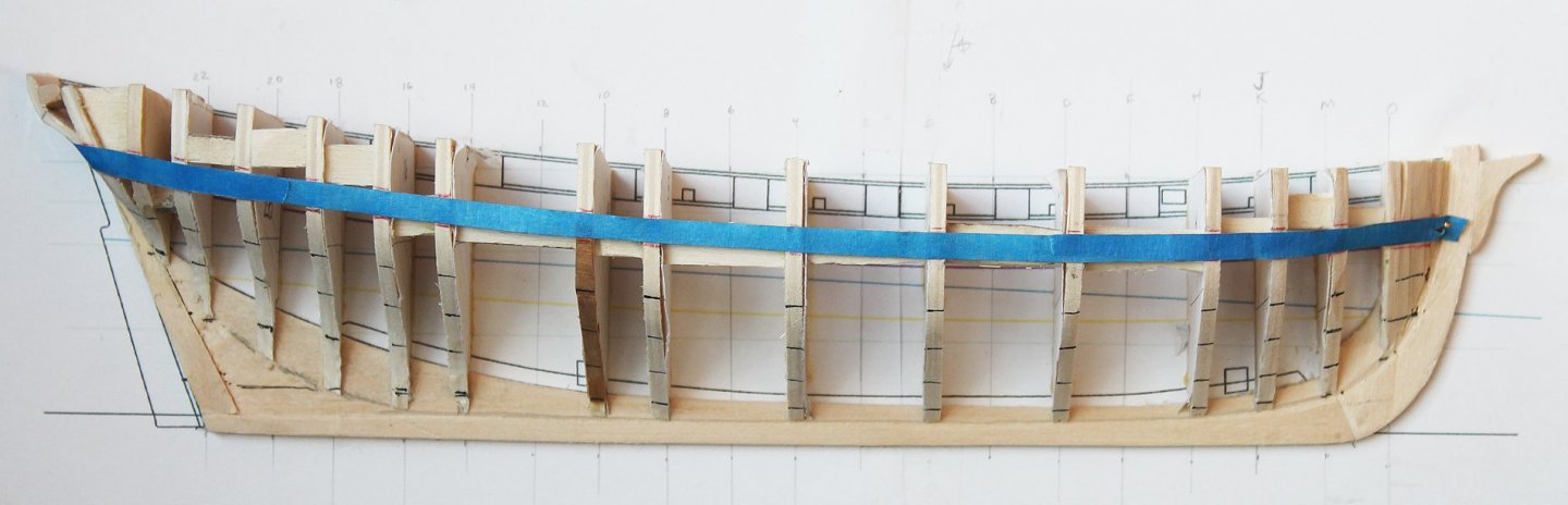
It has been a while since I updated the log but installing bulkheads and fairing a hull just is not very exciting. The fist step in permanently installing the bulkeads is making a building board. This will secure the keel so that the bulkheads (hopefully) will be installed plumb and square. I was able to reuse my building board from Atalanta and simply glued Swallow's waterline plan to the board. I secured two strips of wood on either side of the midline with oversize holes to that they could be snugged against the keel. The bulkheads were cut from 1/4" basswood plywood. I plan on constructing the lower deck amidships so the center of bulkheads F through 14 only extend to the level of the lower deck. The other bulkheads extend to the upper deck. The bulkheads were installed using the same technique seen in the half hull project, clamping them to machinist squares. I also keep a small level on the bulkhead while the glue sets. This becomes most important with the bulkheads that only extend to the lower deck; there is only a narrow slot so it is easy to get them out of plumb. Once all the bulkheads were in place, spacers were installed to stiffen the hull in preparation for fairing. I use a combination of techniques to fair the hull, including sanding discs on the Dremel, sanding blocks and files. One thing which is very helpful for the concave surfaces in the stern is rolling sandpaper around one of the rubber sleeves from my spindle sander. Before I owned the spindle sander I would use a shot glass. The key in fairing a hull is taking a lot of breaks. It is too easy (for me at least) to remove too much wood otherwise. On this hull you can see a few places that happened. Those spots were built back up with strips of walnut from the scrap bin. One techniqe I use to check for a fair run is to take strips of masking tape and run them along the hull. Another useful technique is to run a marker along the bulkhead. As the hull approaches fair, the marker is gradually sanded away. At this point I am reasonably satisfied with the shape of the hull. Several of the spacers become loose during the fairing process. Rather than replacing them, I ran a ribband along the hull, gluing it in place and then securing it more with zip ties. The red marks represent the wale and the bottom of the rail. The plans show the gunports extending to the rail but the model shows an additional row of planking above the ports. I have not decided which direction to go at this point. Neither the plans nor the model are "as built" and it was common to add the extra row of planking to help protect the crew.


- 277 replies
-
- 26
-

-
Doug, any problems will be taken care of with the fairing. Did you apply glue to the part of the frame that touches the plan? That, along with gluing the mating surfaces of the wood, should hold it until you install the filler piece.
-
This is a kit for beginners and intermediate builders. I designed this kit so almost anyone with a little patience and a few common hand tools could complete it. The only power tools I used was a Dremel but it was not necessary. Yes, it is also a scale planking kit. The ship itself is fictitious but the kit is designed as 1:48 scale. This scale is larger than the "typical" kit scale of 1:96 or 1:72. The larger scale makes it easier to install planks that are the correct width and thickness.
-
Thanks for all the likes. Mike, I plan on making the cradle. Gregory, the nuns never taught me that relationship...and they were Franciscans.
-
Jan, thanks for the reference. You are right, the head looks much more like the model, although the model had a figurehead instead of a fiddle head. Zephyr shares the same capstan location as seen on the plans for Swallow (neither of which agree with the model) and there are no gun ports on the transom. I struggled with the whole issue of accuracy for several months before deciding to forge ahead with the project. I guess at this point you could say that I am modeling the plan with the addition of a ladderway (and possibly a companion) and only twelve swivel guns but using the model as inspiration.
- 277 replies
-
- 10
-
-
Jaager, I hope I do not need too much luck but I am happy to accept good fortune. Seriously, I have not looked at Le Cerf. At one point I toyed with the idea of opening up the midships on one side and installing "real" frames rather than bulkheads, showing the frame notches. I am still thinking about it but do not have to make a final decision for a while since I plan on completing the lower deck before starting planking.
-
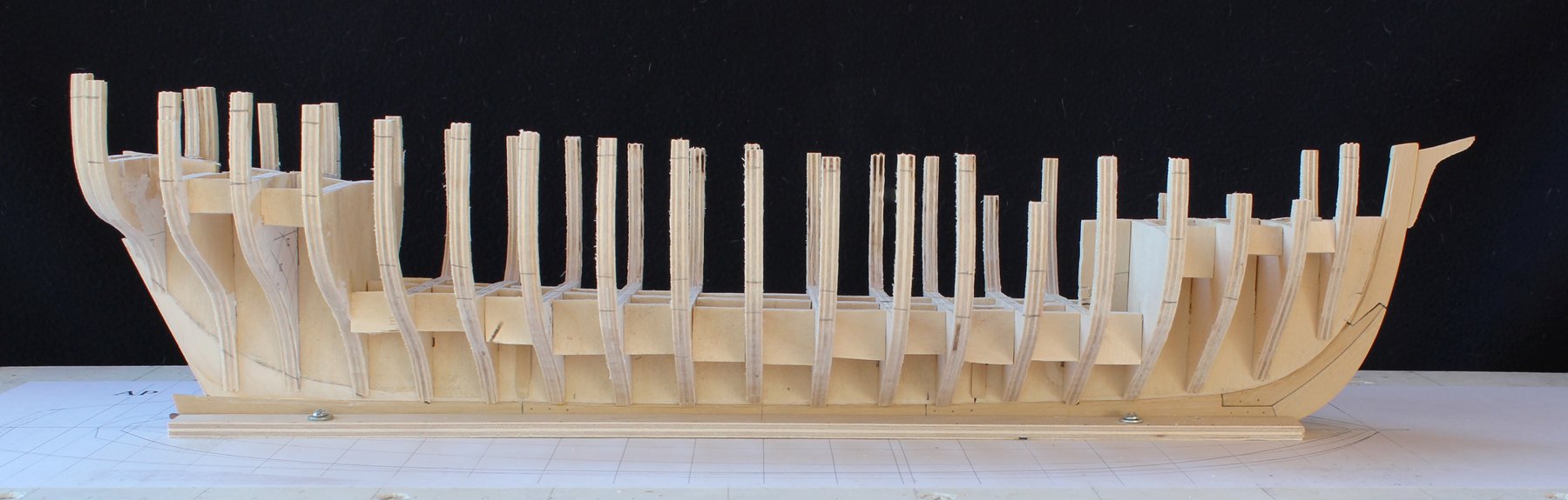
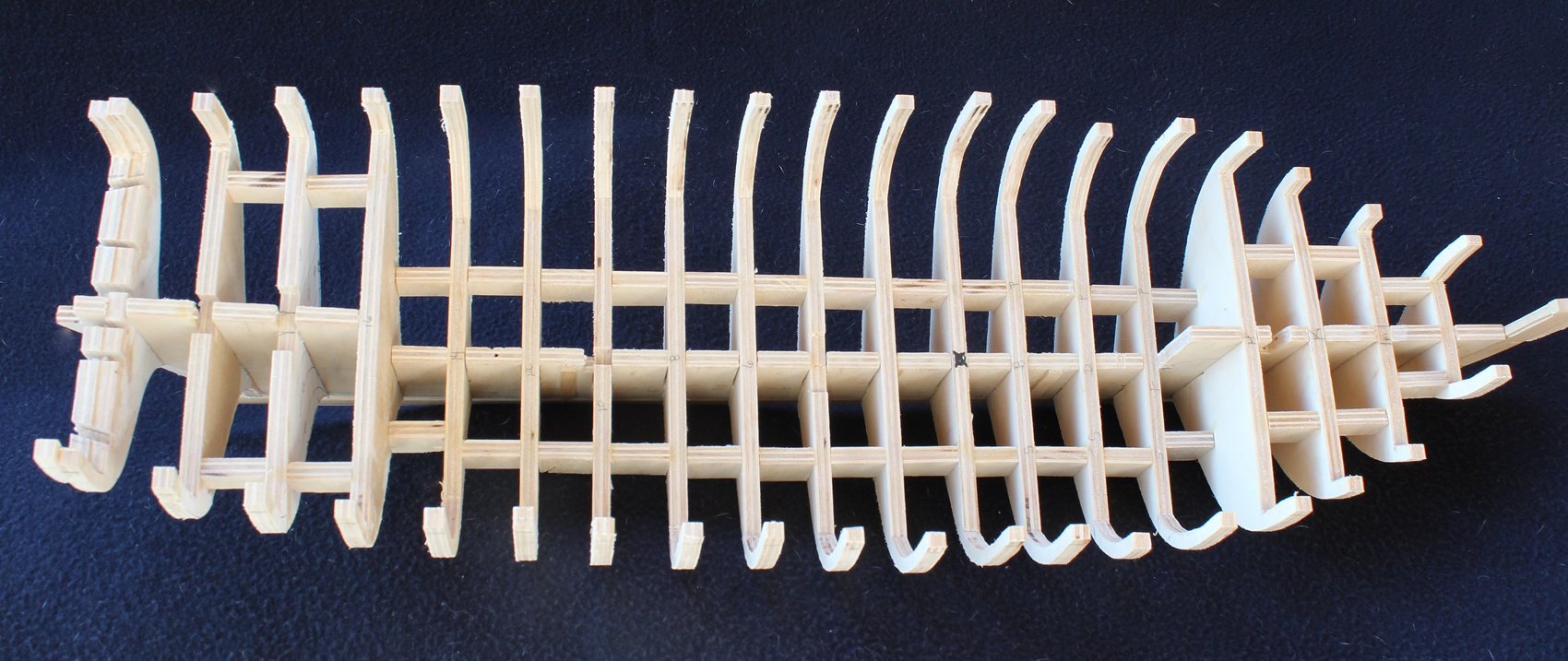
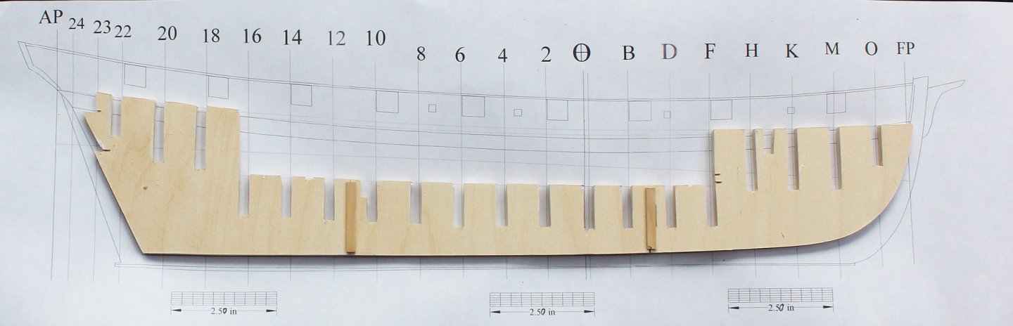
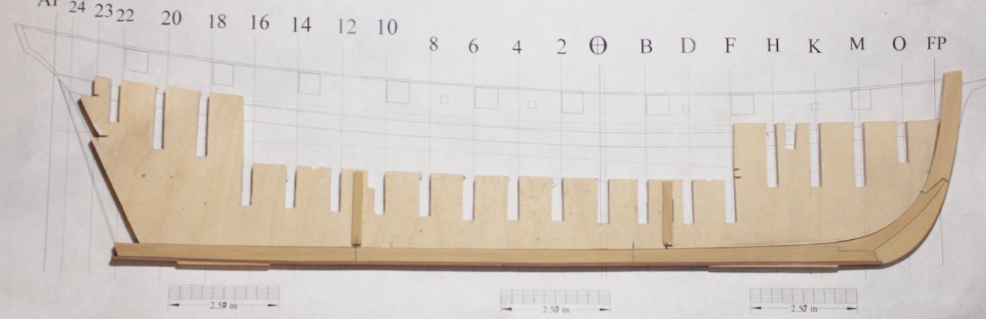
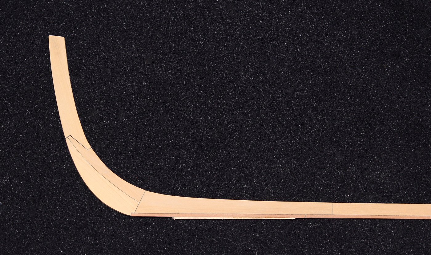
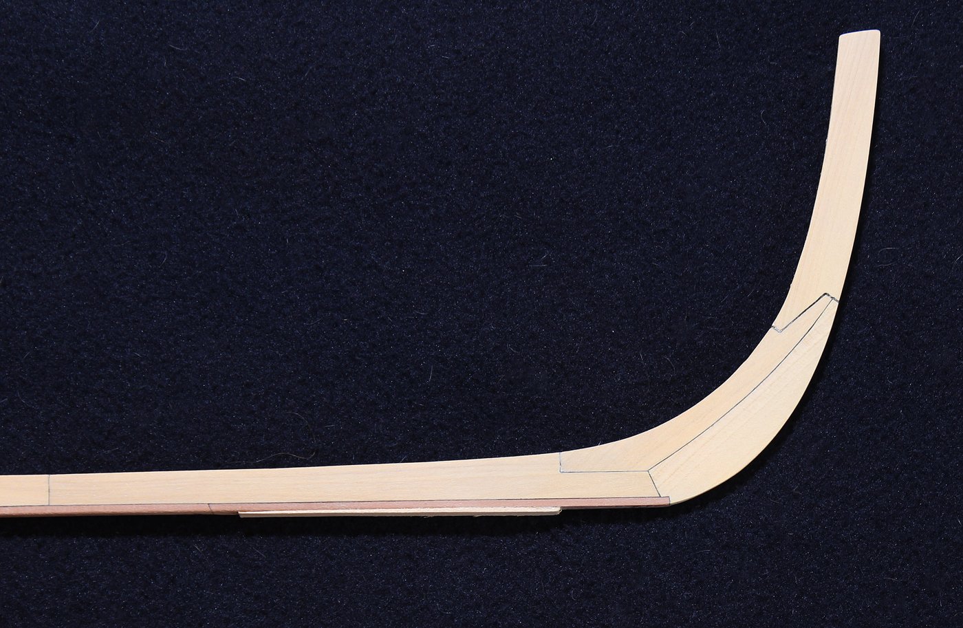
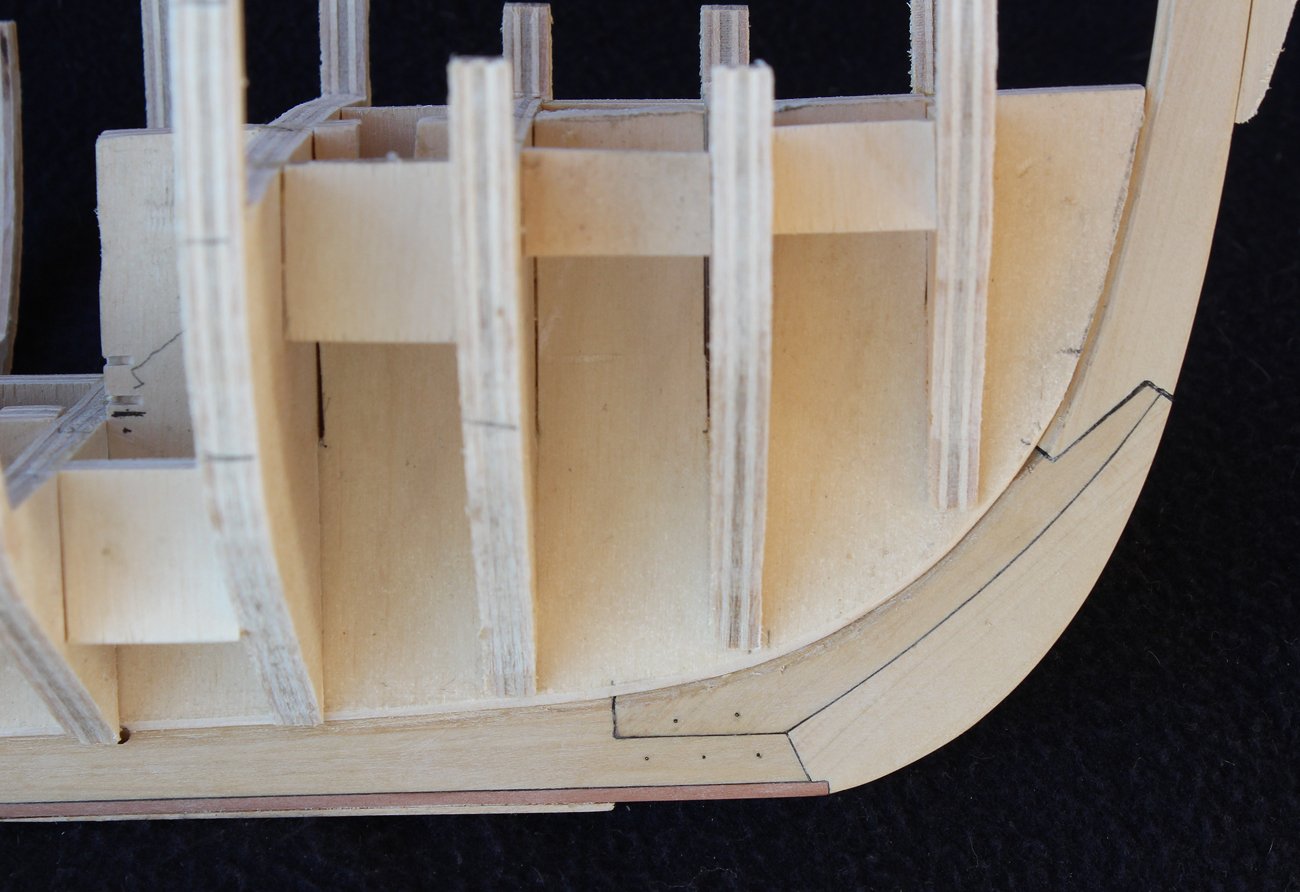
I agree, Greg. That cradle adds a lot to the model. I am using 1/4" basswood plywood for the backbone and bulkheads. The thickness will result in a stronger structure and will give a better gluing surface for the planking. The backbone is made from three pieces and the joints are supported with a strip of scrap. You can see the section between stations F and 16 that will have the lower deck completed. To make cutting the rabbet easier, the upper part was sanded into the backbone before the keel/stem assembly was added. At station O, the angle of the rabbet gradually increases from 45 degrees to 90 degrees and the width therefore becomes more narrow. Just below station FP, where the angle is 90 degrees, the entire width of the rabbet is on the stem. The keel, stem and sternpost are made from costello boxwood. The false keel is pear. The width of the keel is 10.5" based on the RMG plan. This is narrower than the 12.5" dictated in the Establishments but this difference most likely is because Swallow was designed as a merchant cutter, not a military sloop. I do not have any pictures showing the construction sequence, but it is straight forward. The keel was made from three pieces, scarfed together and secured with six bolts. Black paper was inserted into the joints to simulate felt. A 45 degree bevel was cut into the keel from station 14 going forward for the rabbet. Aft of station 14, the deadwood starts and the angle changes. The plan does not show structural details for the stem and I was unable to determine the structure from the model. Based on other ships of this size and era I came up what I feel is a reasonable guess. The width of the stem is 12" at the head, diminishing to 8" at the keel. These joints also have black paper to represent felt. Brass wire was inserted through the inner part of the stem to secure the pieces together. The pictures show the stem before the rabbet was cut. The bottom of the keel is curved fore and aft. In order to keep the hull stable on the building board, I added scrap basswood to the bottom of the false keel. The photo shows a test fit between the backbone and the keel/stem assembly. Although this picture is taken out of sequence, it shows how the keel and stem were bolted together.
- 277 replies
-
- 26
-
-
Agree with you 100% Dan. I plan on adding fillers in the bow and stern areas to facilitate planking.
-
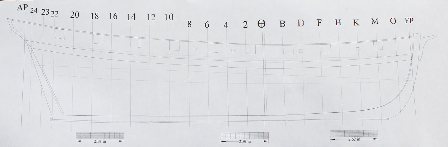
A few years ago, I was looking at some of the models posted on the RMG website and came across Swallow 1779. I instantly was attracted to her overall appearance and the fact that she was clinker-planked. The model is listed as SLR0540 and the plans are ZAZ4719. Swallow did not have a long career. According to Rif Winfield, in his book “British Warships in the Age of Sail 1714-1792”, she was purchased on the stocks in 1779 and was originally designed to be a cutter. On the sheer plan one can see where the original mast (located at the dead flat) was erased from the plan. She was registered as a sloop and originally carried fourteen 4pdr guns. The following year, four 18pdr carronades were added. There is no mention of swivel guns, although the plan shows mountings for twenty-two of them. With Lively, Swallow captured the US privateer Black Prince in 1779. She was coppered in 1780 and on August 26, 1781,, Swallow was run ashore and burnt to avoid capture by US privateers off Long Island. The first order of business was to develop a set of plans. Comparing the plans with the model revealed several inconsistencies. Starting at the bow, the model has a much larger stem with cheeks, rails, a false rail and a figurehead. The bowsprit come out of the hull in the midline. The plans show a simple stem and the bowsprit exits the hull to the port side of the stem. The model shows the capstan at midships but the plan has it aft of the main mast. The locations of the various hatch covers also differ between the model and the plan. There is a difference in the deadeye configurations and the swivel guns are not modeled. Finally, although the gold detailing is stunning, this little boat certainly would have never been decorated in other but the simplest schema. To make things even more confusing, in small print on the plan is the following..."a copy of this was given to Mr. Ladd for finishing two cutters the Board bought of him when half built 9 Feb? 1779". And, yes, the question mark was in the sentence as written. So the plan is actually the proposal for finishing and not as-finished. I had to decide whether I was going to model a model or model a ship. Because the model is most likely a presentation piece, I decided to use the plans layout rather than the model's. This still left me with concerns. The biggest one was whether to model the swivels. Since the model does not show them and Winfield does not mention them, I decided to leave them off. There is also no "proper" access to the lower deck on the plan but a companionway is visible on the model. I have added a ladder and companionway. If any of you have additional information or insights to the contrary, please let me know. Things are easy to change at this point. This was going to be a plank on bulkhead model. My reason for this construction style was that the beauty of this ship will be in the clinker planking; therefore, both sides of the hull will be completely planked. I will be installing the lower deck and its associated fittings in the mid-ships area as I plan on making the hatch covers removable. Plans were developed using the tutorial written by Wayne Kempson which is found in the Modeler’s Database. http://modelshipworldforum.com/resources/plans_and_research/DraftingShipPlansInCADwayne.pdf TurboCAD 18 was my CAD program. Once the plans were developed I made a half hull in 1:96 scale to make sure that I did not have any glaring errors in my rendering.
-Warship-Brig-Sloop-14-guns-0a.jpg.e3f885d62571cfd7901348984918a400.jpg)
-Warship-Brig-Sloop-14-guns-1a.jpg.b44bc9297c470b4b90d66c3e240c9029.jpg)
- 277 replies
-
- 34
-
-
Looking forward to seeing it in the New Year.
-
Looks great. Only the first run of kits have the bulkhead issue. Please remember that I have never designed anything before and what looks correct on paper (or CAD) does not always translate perfectly when dealing with a laser cutter and different versions of the same software. As soon as there are five builds started we will set up the group build.
-
The Board discussed your request again last night, Christian and Ed. We will not be offering the kit in a plans and manual only version. There were several issues raised but the most critical is the fact that this is aimed at the novice model builder. They would not be expected to have the necessary equipment and skill to be able to accurately cut out the components.
-
Christian and Ed, the NRG Board has discussed your situation and we had decided not to make the plan and instructions available as a stand-alone without the kit components. We can talk about it again.
-
Mark, I developed the kit with the idea of turning it into a group project. As soon as a few people start build logs we will get things started.
-
Maury, with the softness of the basswood I find the surface visually smooth but when I rub my hand along it there is still some roughness. With hardwoods I usually stop at 400. It only takes a few minutes to sand it further because I am only sanding the lower hull, not the wale or bulwark planking.
-
Actually, I don't remember what my logic was. That was almost seven years ago. But in general I work from the bottom up.
-
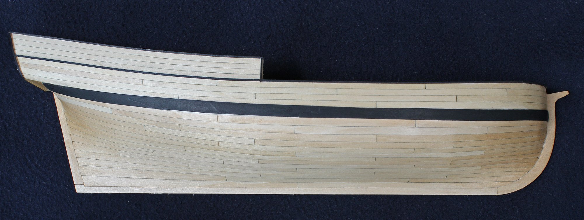
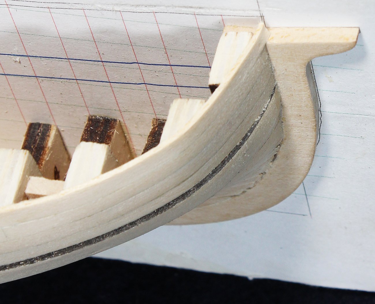
The outboard edges of the transom planks are protected by a black decorative strip. This was carried down across the bottom of the transom to seal the junction of the transom and counter. This was done with one piece of basswood that had been wet and then slowly bent to the required shape. Finally, the taffrail was installed. The hull is now completed. At this point one could add treenails but I have chosen not to...maybe some day. I was asked about ports by one of our members. If one were to install ports, it would be necessary to finish the inside of the hull, as this would be visible through the ports. Although possible with the use of sanding discs, it would take a lot of effort to remove the frames. Don't forget that these frames were selected for strength so the hull would be stable during construction. There was never any thought that they might be trimmed/removed later. The hull is finished with one coat of Watco's Danish Wood oil and then buffed with a cotton cloth. The hull was removed from the building board by inserting a razor blade inserted between the hull and the paper pattern. It is surprising how strong this hull is. I do not plan on mounting her but if one wanted to I would suggest covering the open parts of the hull with a sheet of basswood, either left natural or painted black. Here is the final result. I hope this project will encourage some of you to take the plunge and plank your next hull the way it was originally done.

- 167 replies
-
- 19
-
-
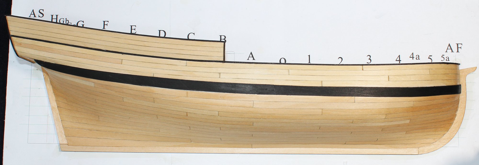
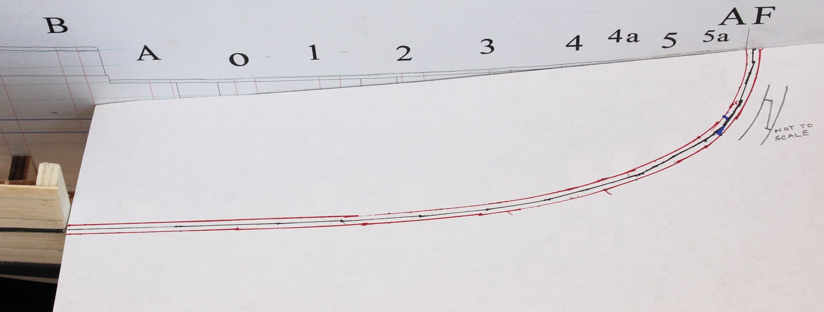
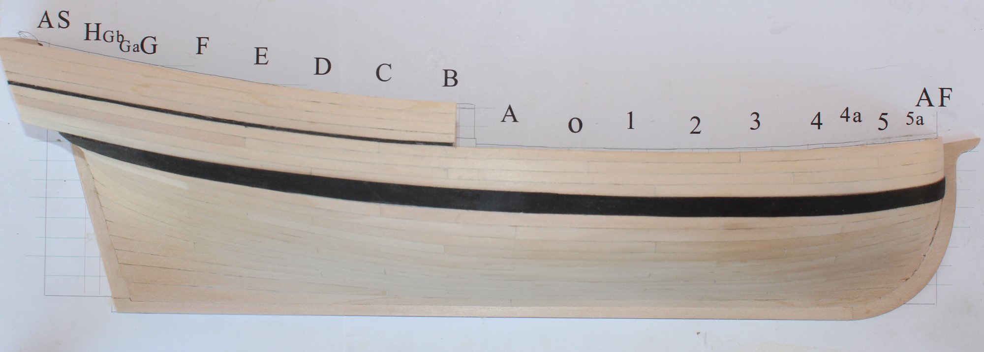
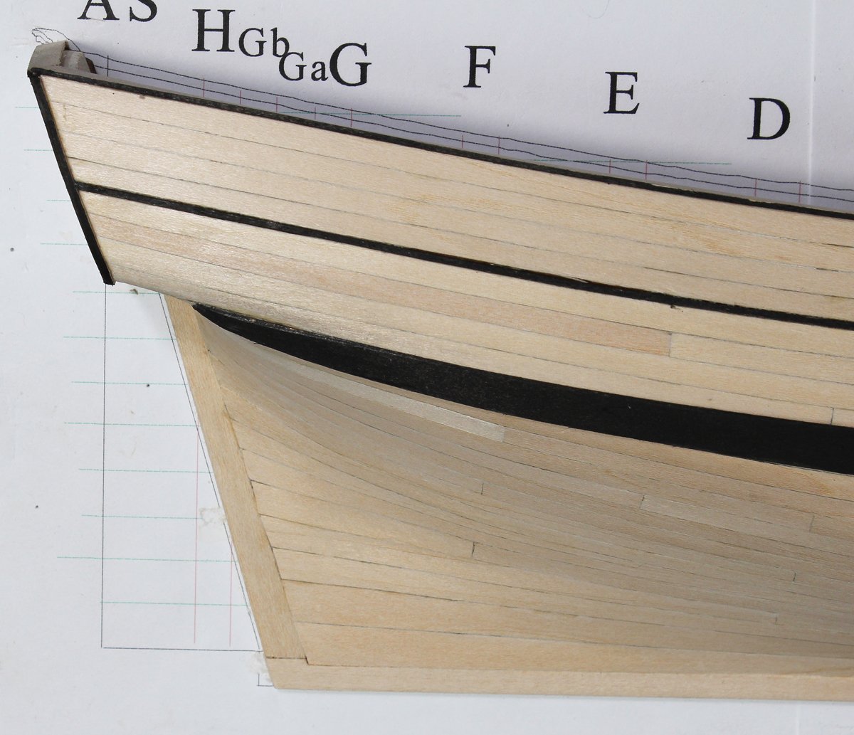
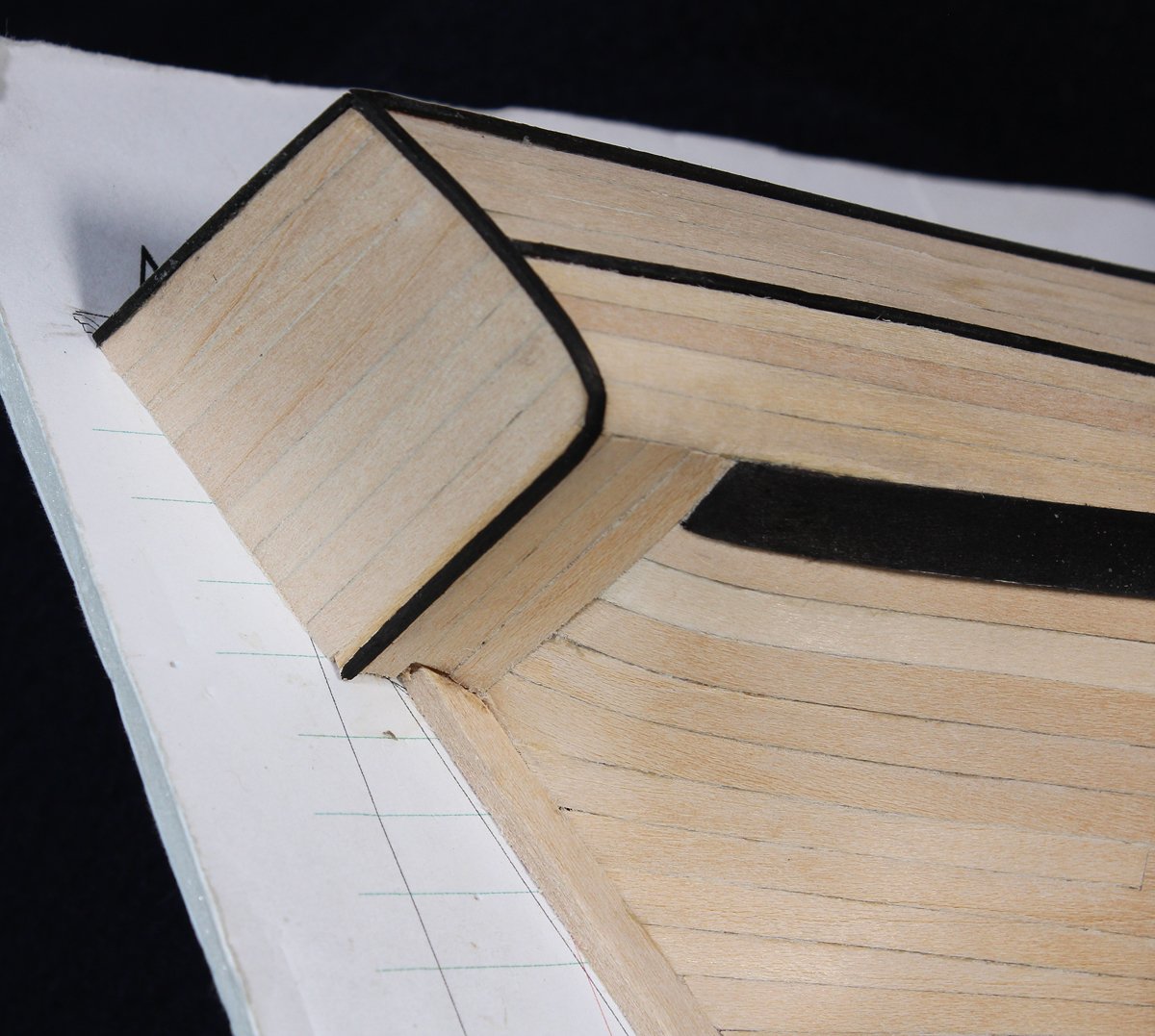
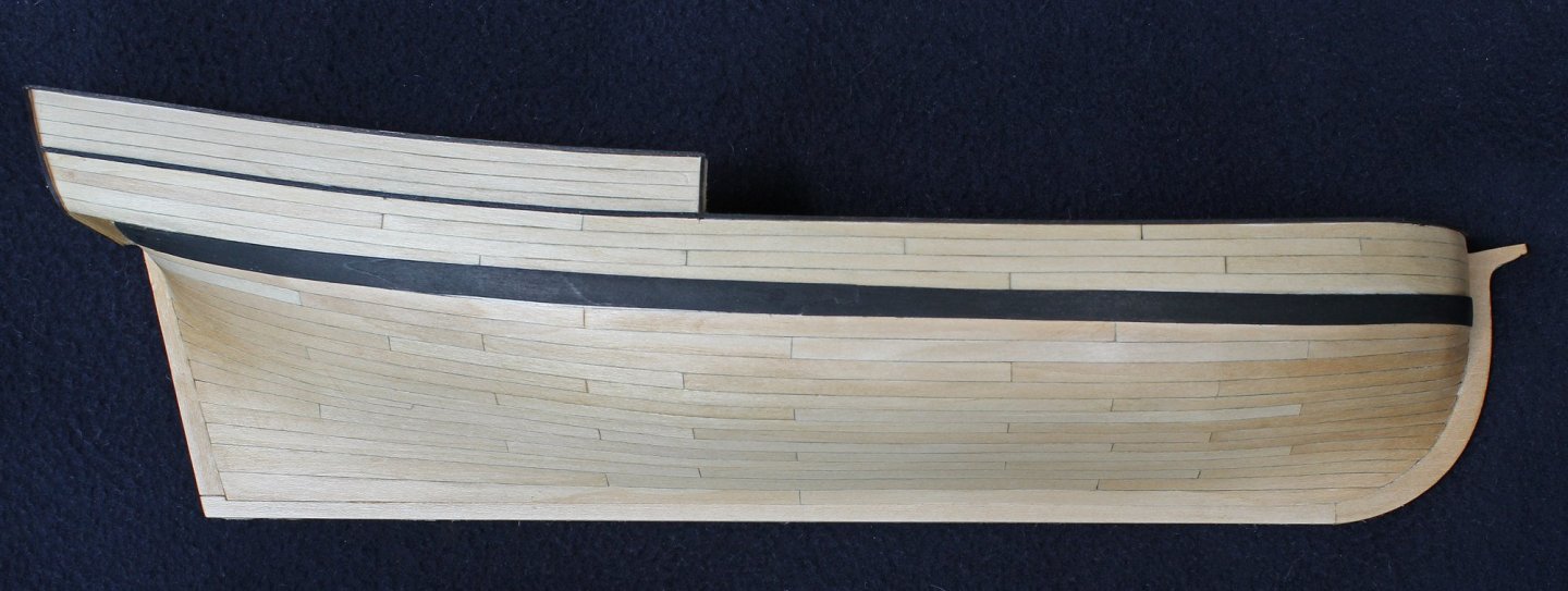
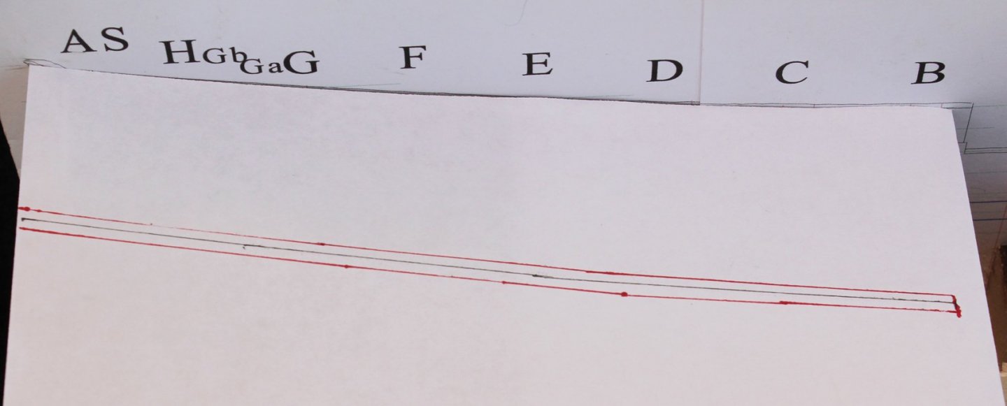
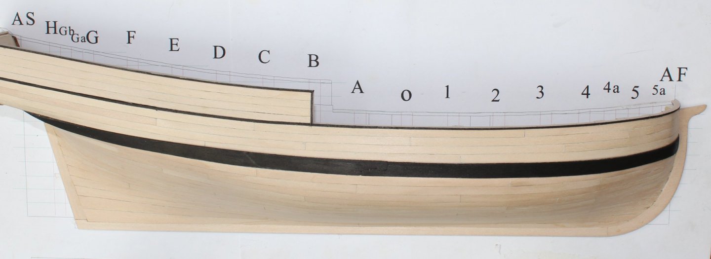
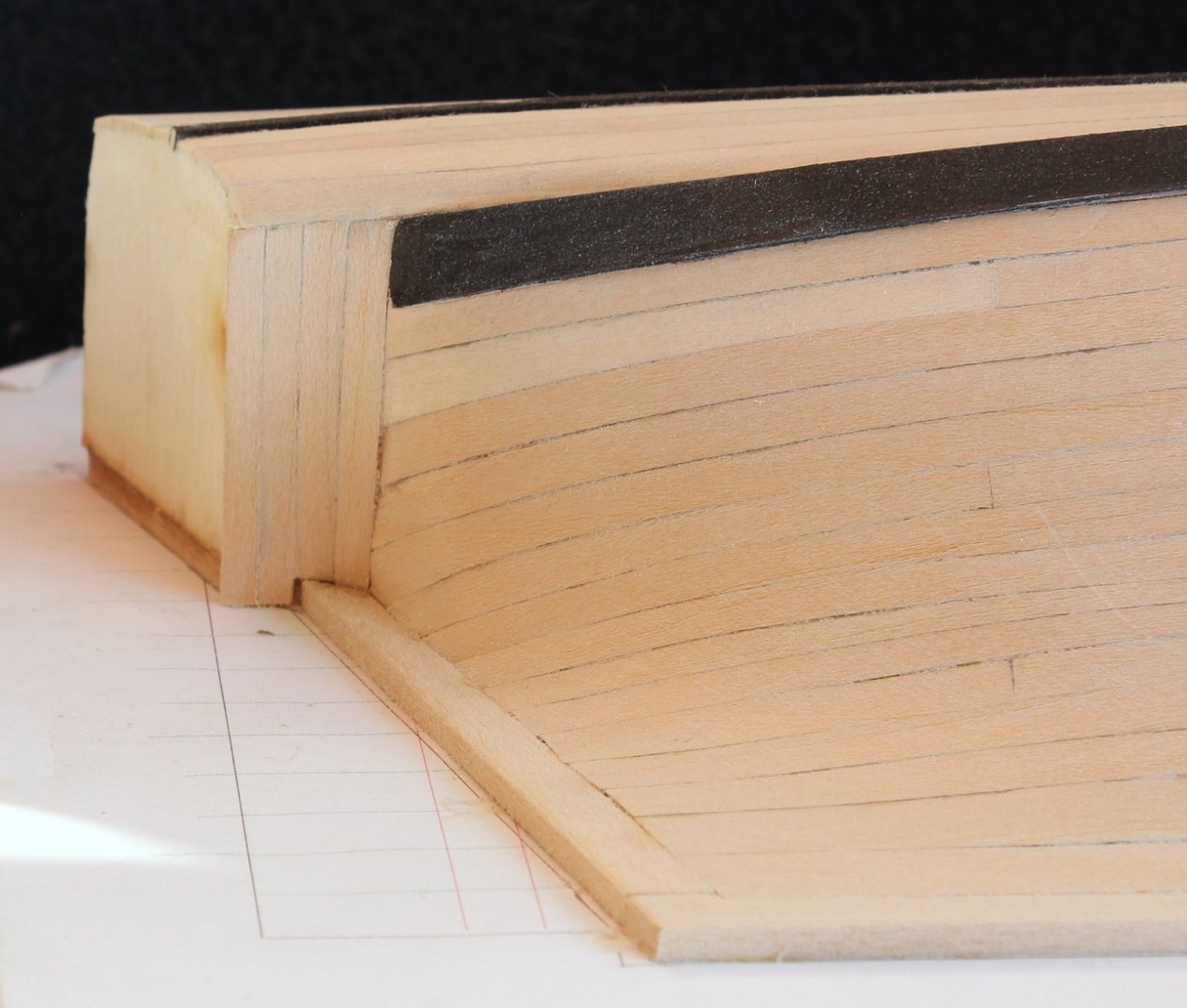
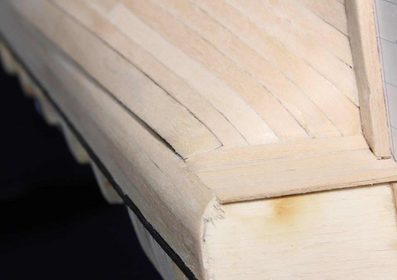
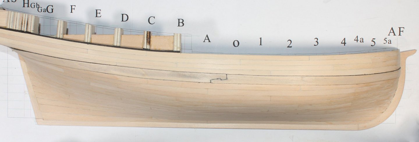
There are four rows of counter planks. You can see that the upper counter plank extends beyond the counter. This is to allow a good fit with the transom planking. Remember that the lowest row of the bulwark planking was not trimmed so that it would protect the end of the counter planks. And the lowest row of counter planking protects the ends of lower hull planks. Everything is designed to prevent water penetration into the wood. Later I will install a trim piece to protect the ends of the bulwark planks. The aft end of the wale is now sanded down to blend into the counter planking. After they were installed, the lowest bulwark plank was sanded to conform to the curvature of the counter. The wale has not received its first coat of dye. I will eventually apply three coats. The four rows of quarter deck bulwark planking are straight forward. The transom has been planked and the junction between the counter and the transom planking as been cleaned up. The easiest way to determine the shape of the cap rail is to lay a piece of paper along the top of the bulkheads and trace the outer edge of the planking onto the paper (black line). I have chosen a rail width of six inches and have drawn a line three inches inboard and outboard from the traced line (red lines). There is a significant curve in front of Frame 4a so I made the rail in two sections with a simple scarf joint at Frame 5. It is drawn in blue ink on the picture below. The shape of the quarter deck cap rail is determined the same way. It is made in one piece. For aesthetics I dyed the edge of the rails before installing them. There is also a vertical piece at the break of the quarter deck which protects the ends of the quarter deck bulwark planks. And here are the results.


-
Thanks for reminding me. I have never used the cedar. This project is actually the first time I have used any type of softwood on a single planked hull. I am surprised at how nicely it finishes up. It's biggest downside for me is the dents left behind by clamping, although most of those will come out by putting a drop of water on the dent and letting the wood absorb it. This makes the wood fibers swell but after the wood dries out again, the dent is much less apparent.
-
Maury, what is AYC? Bruce, I use a razor blade to release the model from the paper. Some of the paper comes off as well, but a little sand paper takes care of it.
-
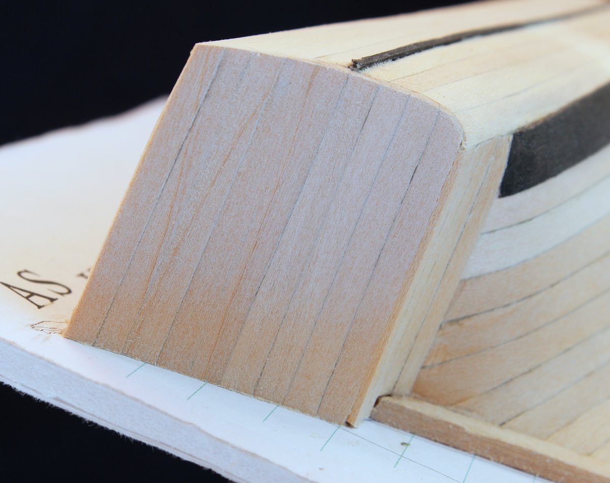
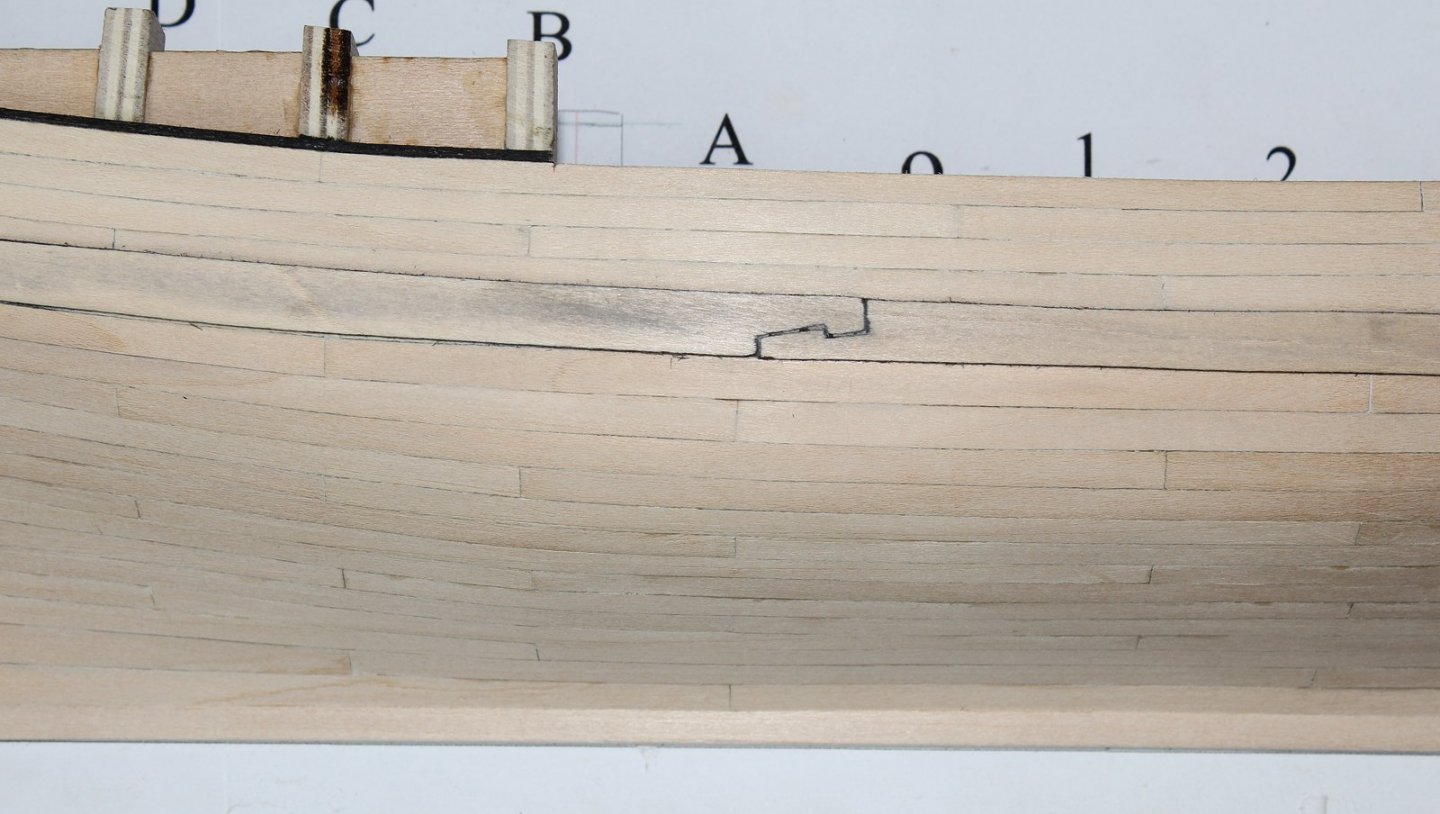
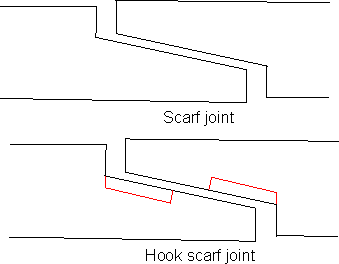
Now that the hull is perfectly smooth, the second layer of the wale will be installed. Since I had saved the template for the first layer of wale planking, it was easy to cut out two more pieces. Just for fun I made a hook scarf connecting the two pieces. To to this I made the mating edge of the planks longer to take up the scarf. The scarf was drawn onto the plank and cut out with the knife. I dyed the joint edges and the sides of the planks before installing. At the bow, the wale ends in the rabbet. Since the rabbet does not become wider to accommodate the wale, the wale decreases in thickness as it enters the rabbet. Something similar occurs at the stern. The picture shows the wale tapering in thickness as it approaches the counter. The counter has not been planked at this point but after it has been, the wale will be sanded down to fay into the counter planking.

- 167 replies
-
- 13
-