tlevine
-
Posts
2,033 -
Joined
-
Last visited
Content Type
Profiles
Forums
Gallery
Events
Everything posted by tlevine
-
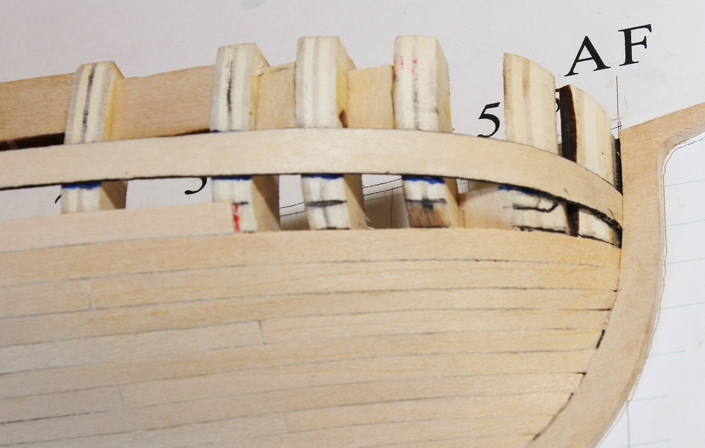
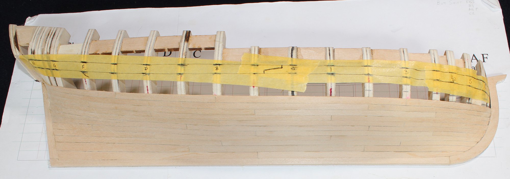
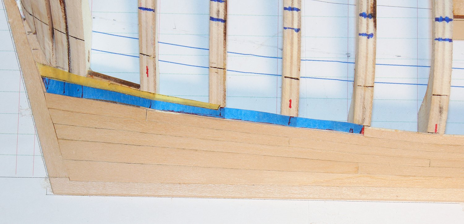
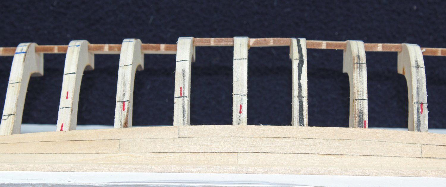
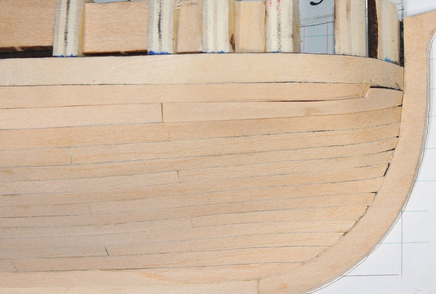
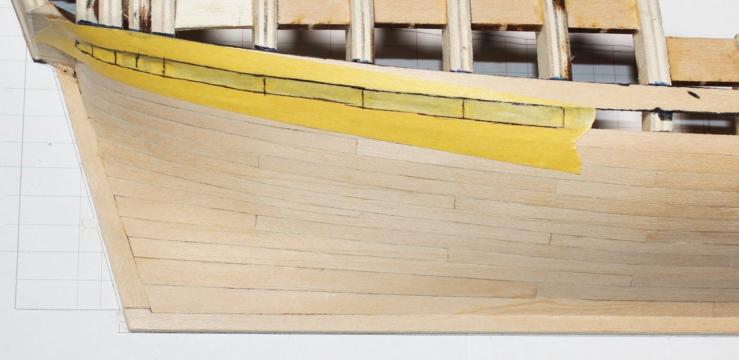
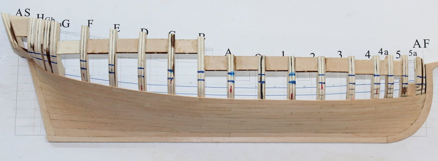
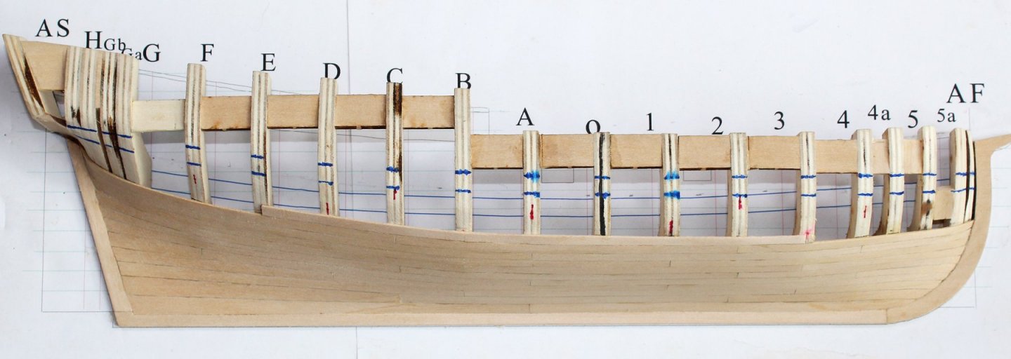
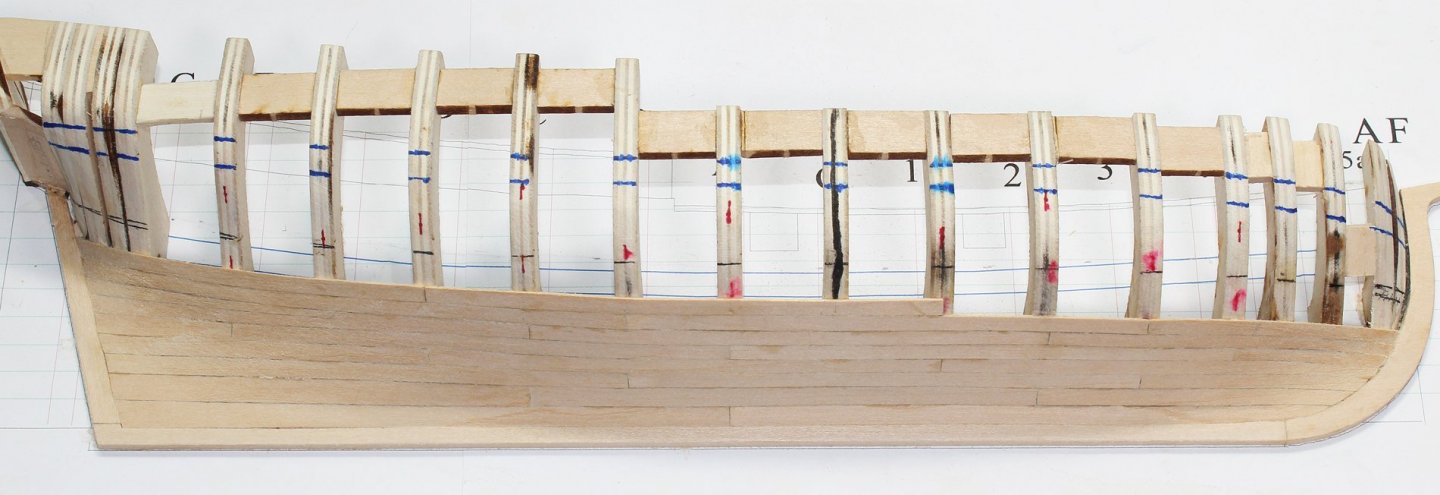
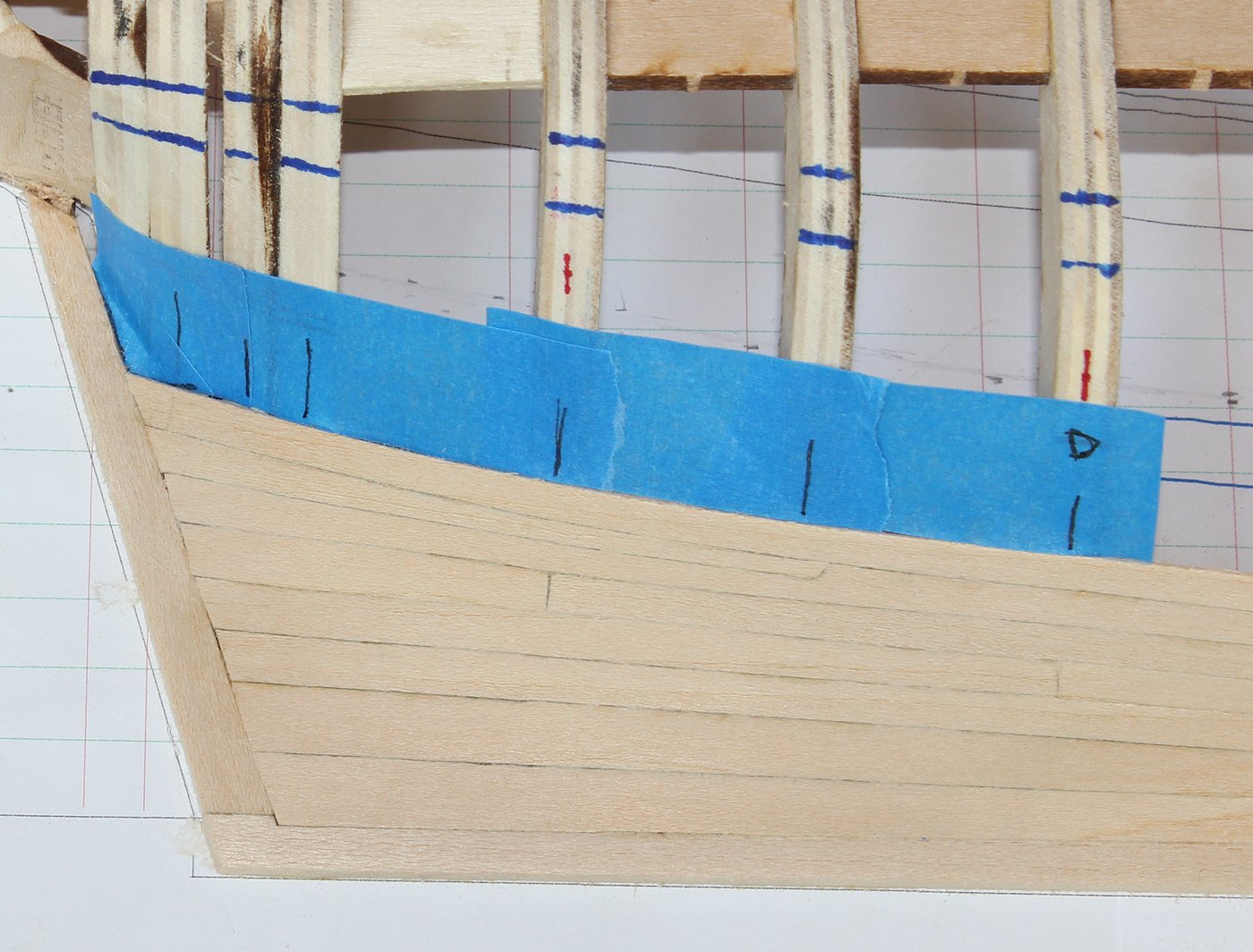
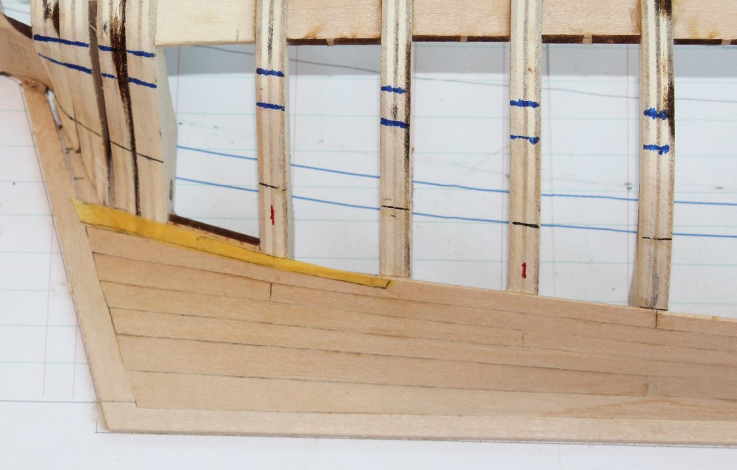
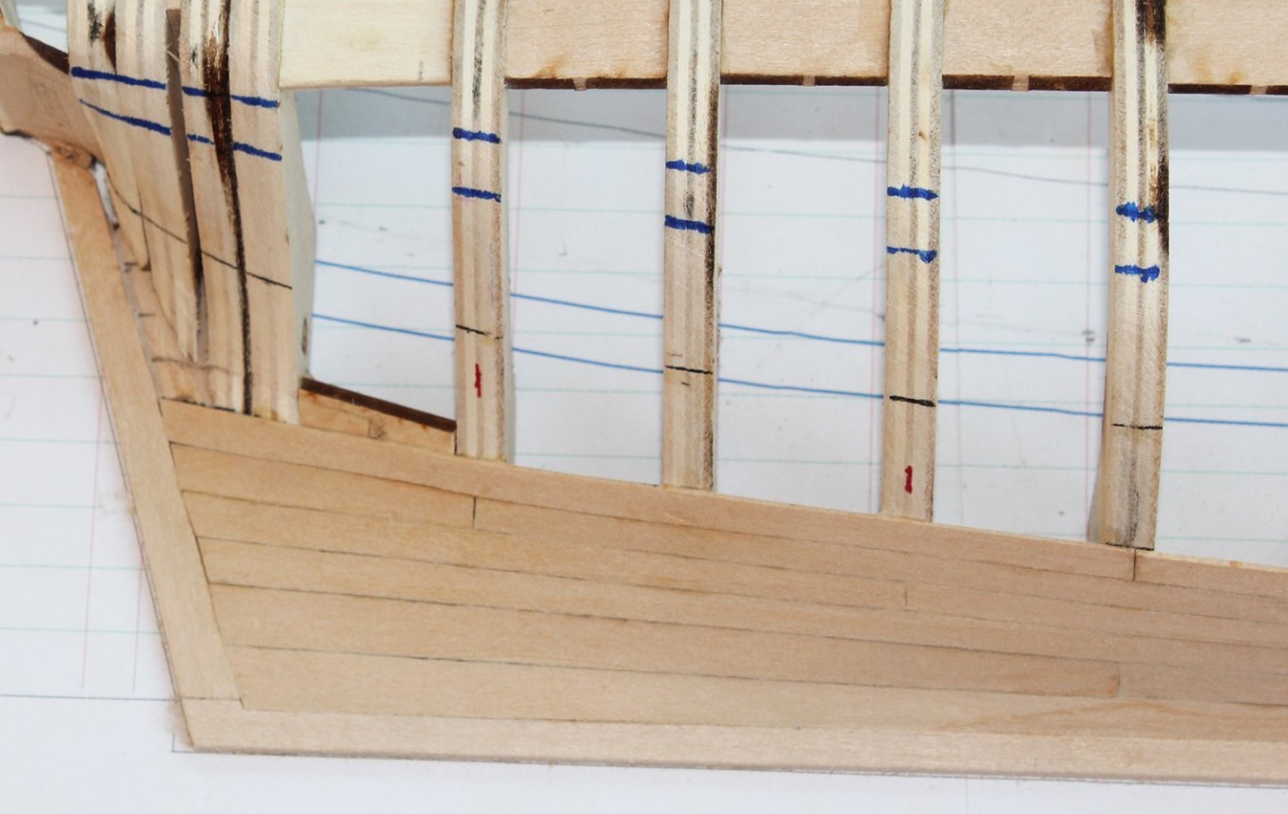
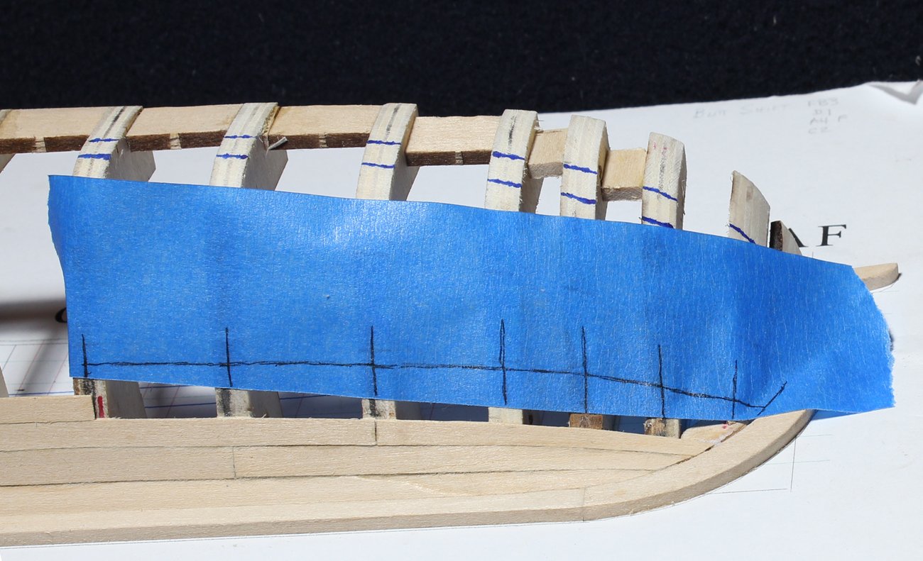
 I have chosen to add a decorative strip approximately at the level of the quarter deck. This will appear to be continuous with the main deck cap rail. I used chart tape to determine the run of the strip. This also happens to be the same width as the strip so it gives a good visual representation of the final result. The upper and lower edges of the strip were drawn onto the frames and filled in with marker. There are four rows of planking between the wale and the decorative strip. The butts of these planks were drawn onto the frames in red and the width of the planks was drawn in black. These planks are straight forward to install, requiring minimal spiling. At the stern, leave the excess wood on the lower row. The ends of counter planking will be covered up by this. This is the perfect time to sand the hull. All the planking from the main deck cap rail to the keel is the same thickness, making the job much easier. I start with 120 grit and progressively sand up to 1500 grit. With the finer grits, I wet the hull first and then sand. This gives it almost a burnished appearance. The decorative strip has been applied. This is 1/32" thick and 1/16" wide, so it stands proud of the hull planking by 1/32". I dye the wood before gluing it to the hull.

- 167 replies
-
- 10
-

-
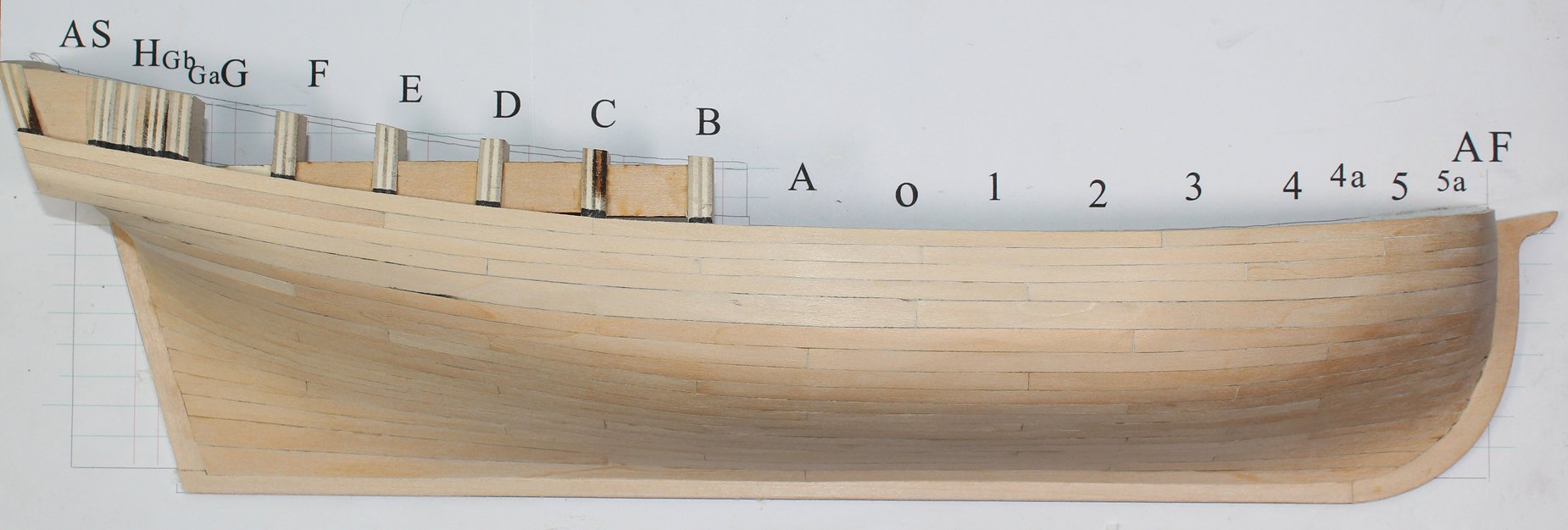
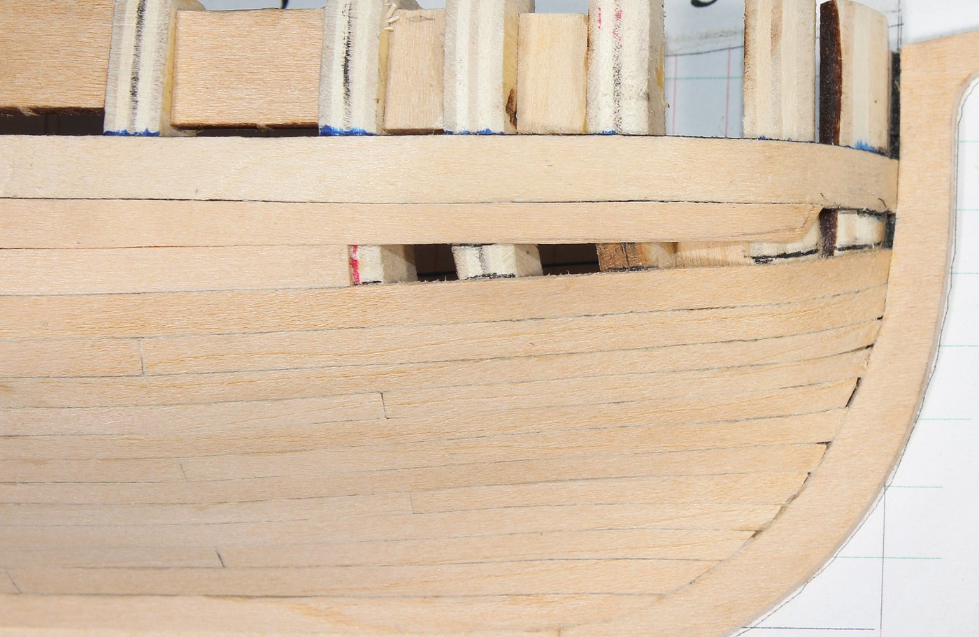
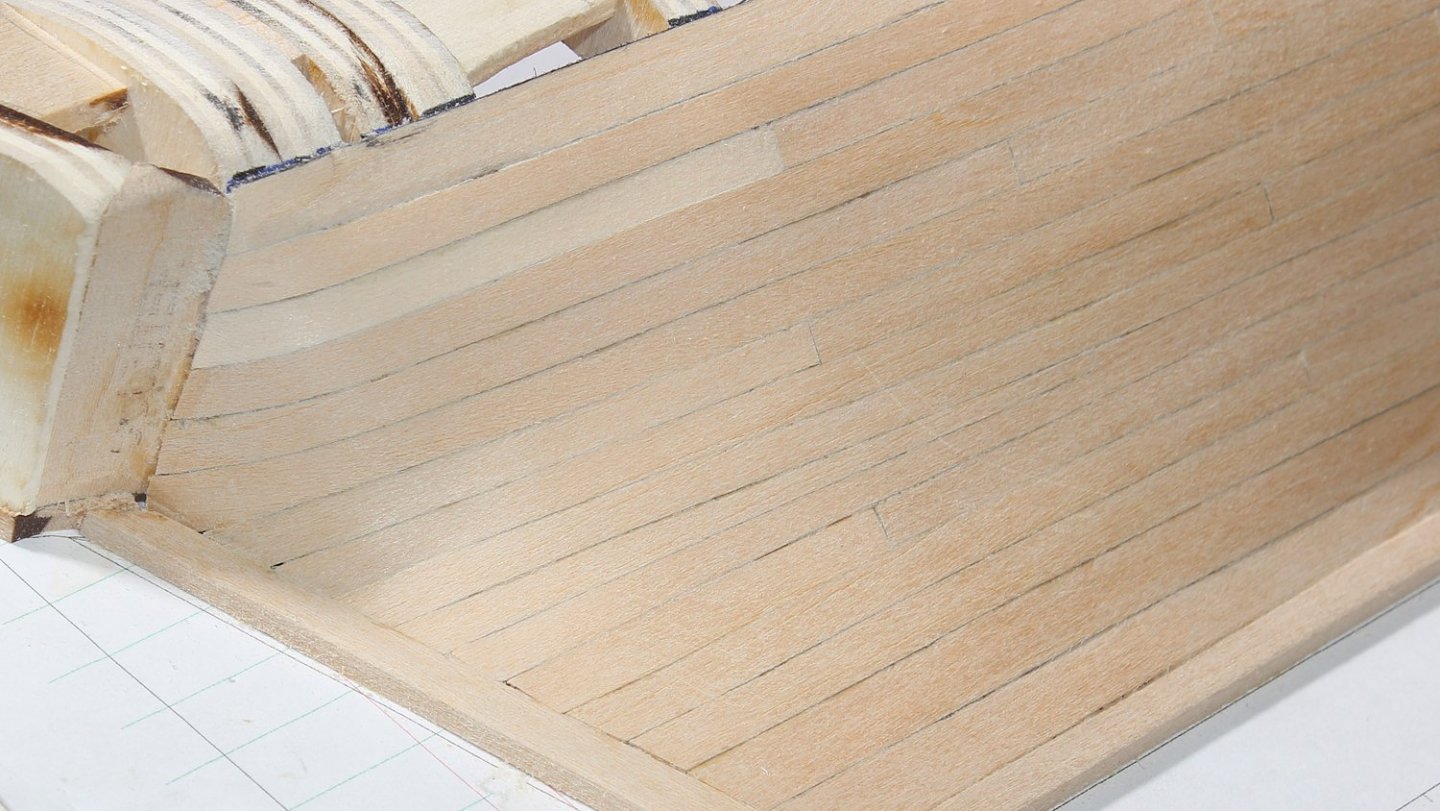
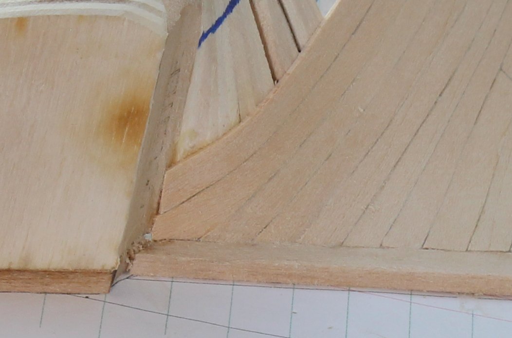
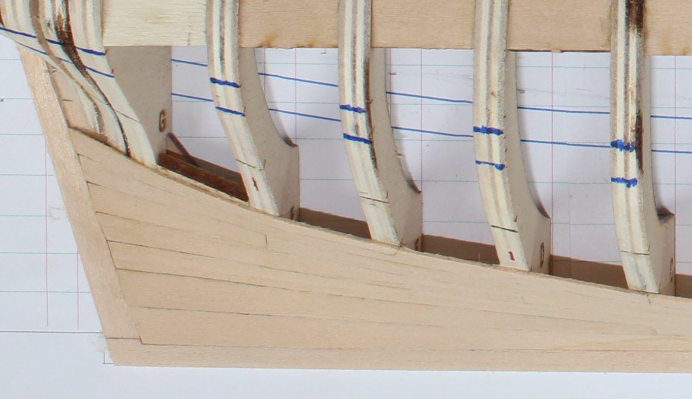
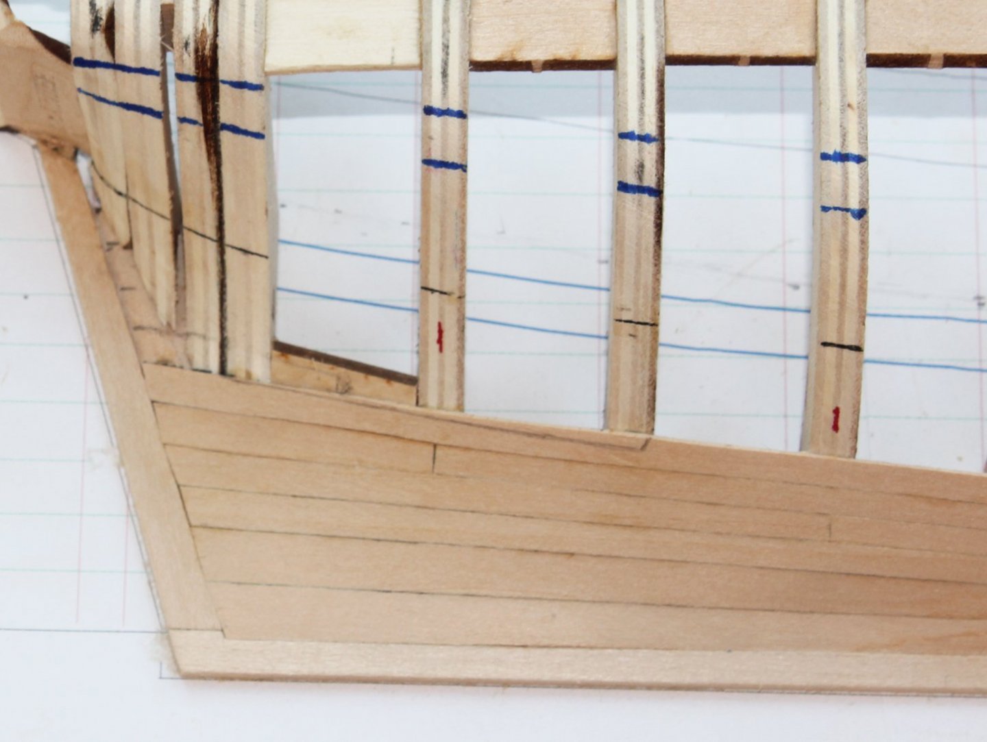
The aft two planks of the upper row of planking were installed. The fore plank (the one which will be dropped) was cut out a bit over-sized and bent to shape by wetting and clamping it to the hull. At this point it is not permanently installed. The fore plank of the third row was then trial fit by laying it over the temporarily installed drop plank. The drop plank was then trimmed to fit and they were both permanently installed. Here is the final result. Everything has been planked below the wale.
- 167 replies
-
- 12
-
-
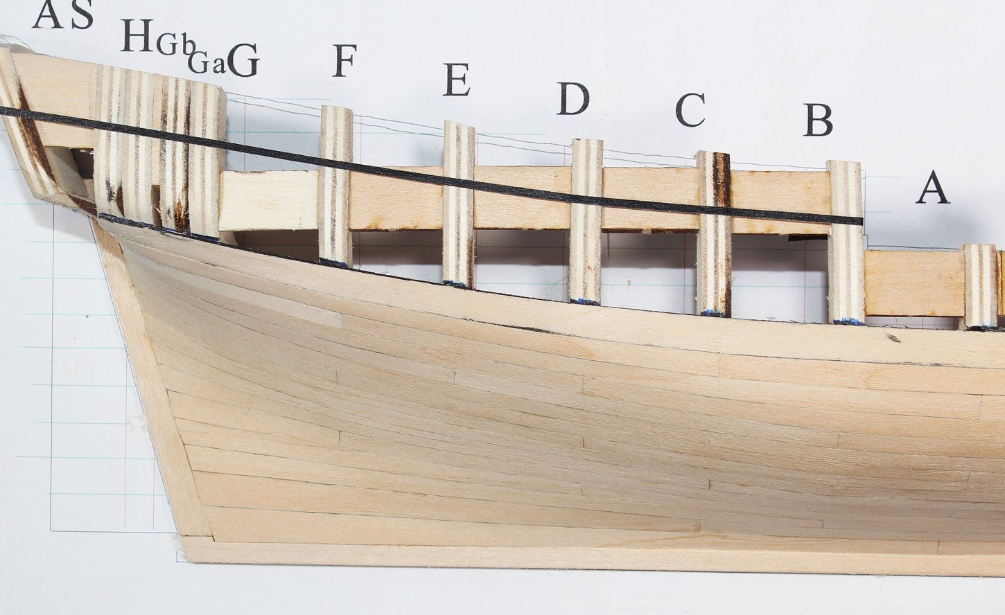
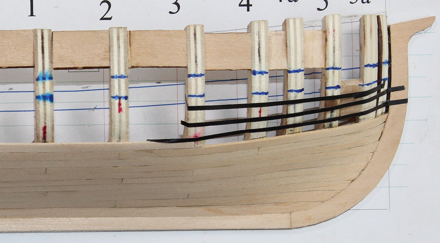
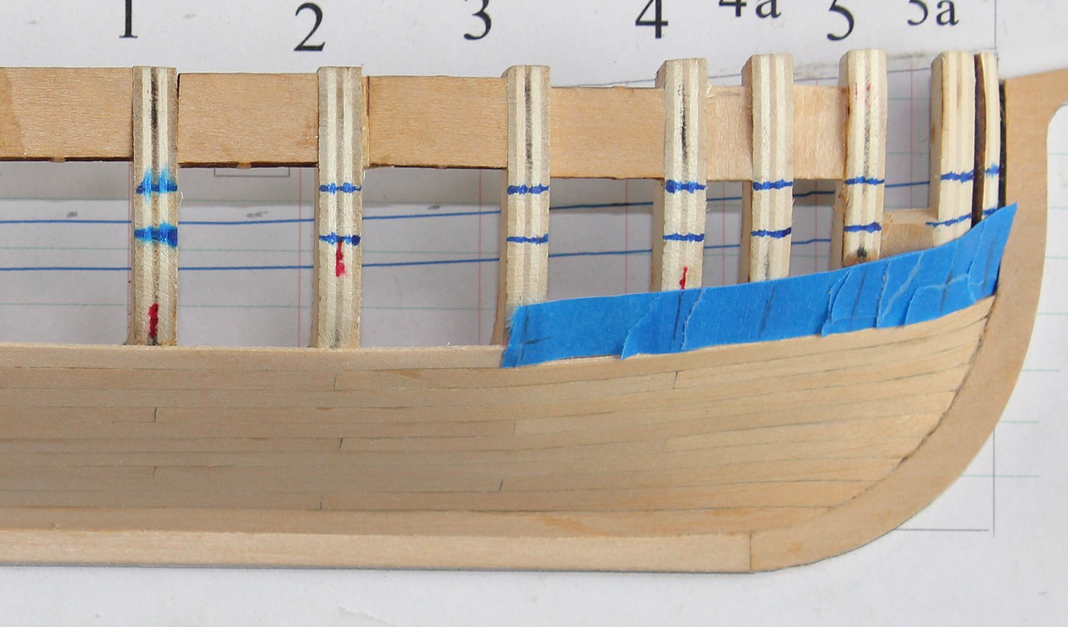
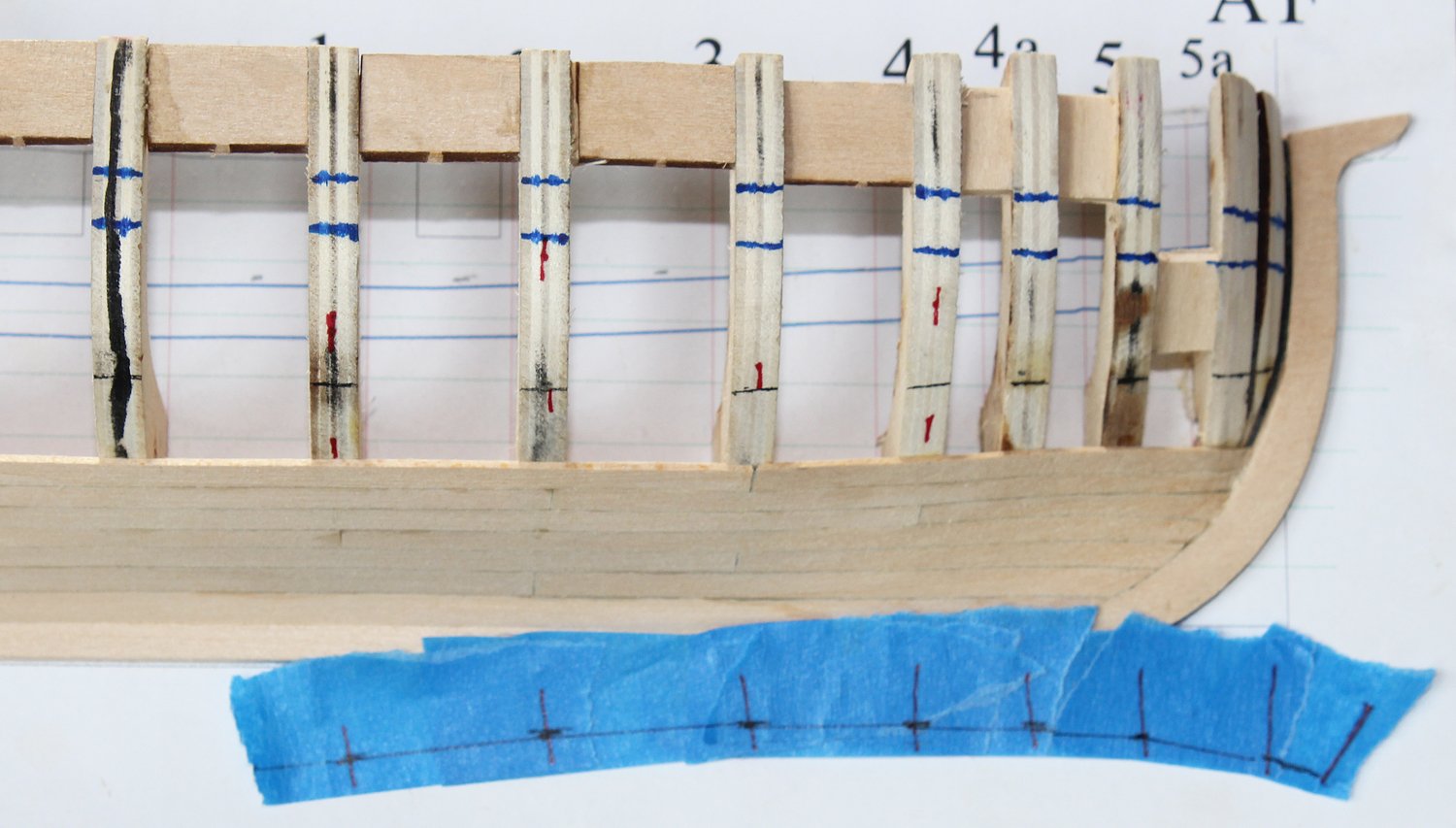
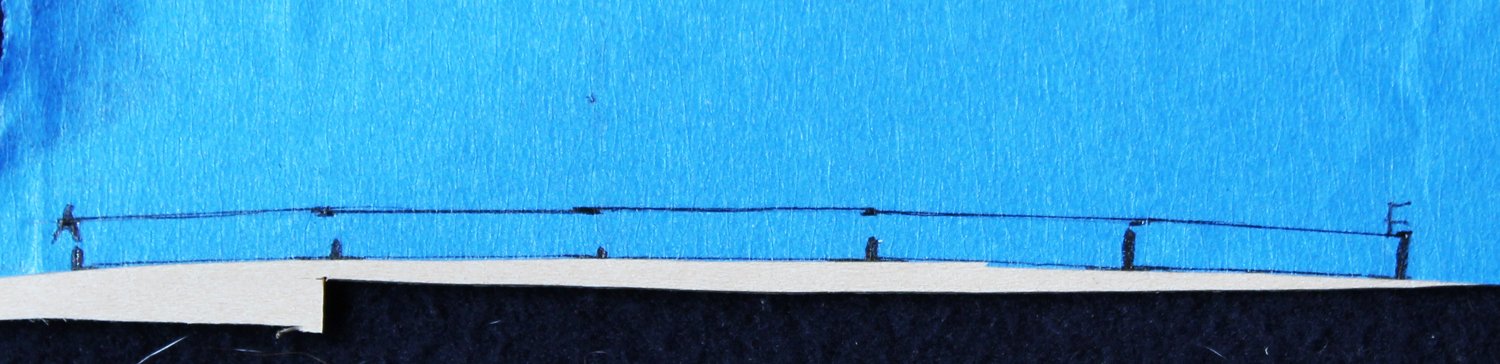
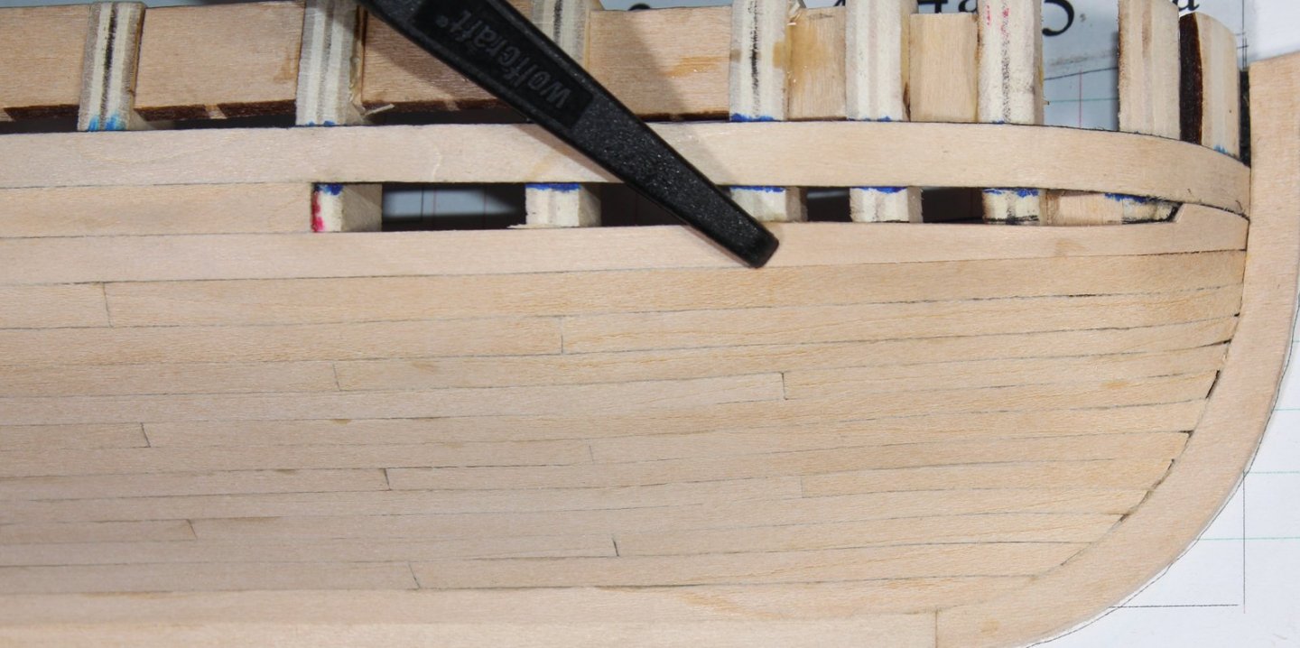
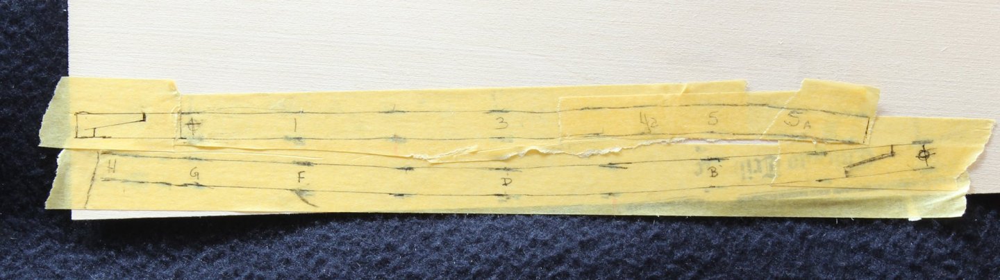
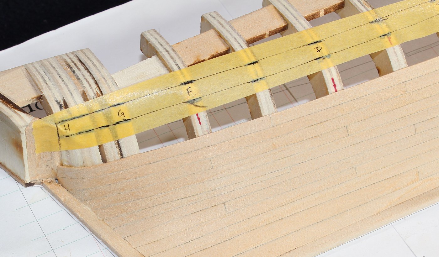
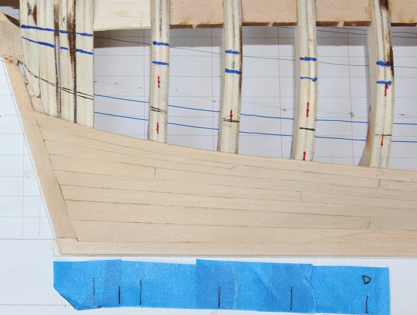
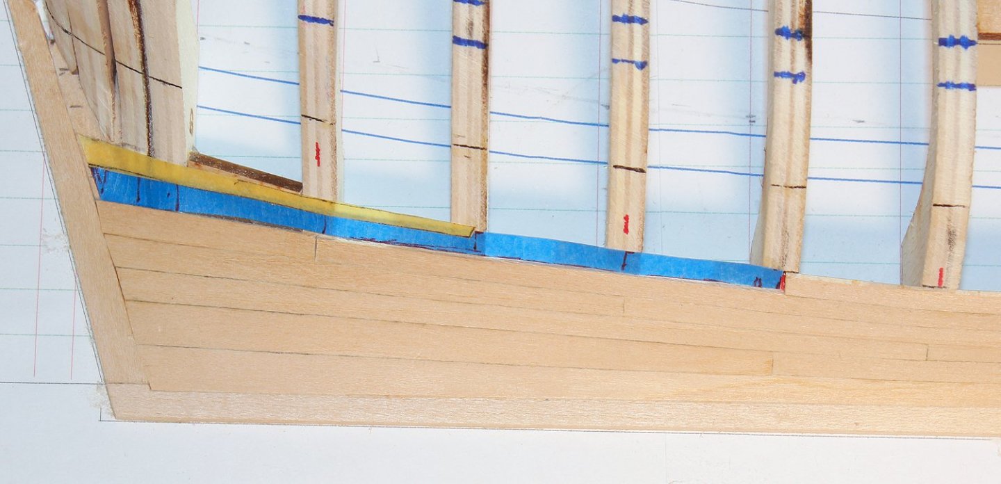
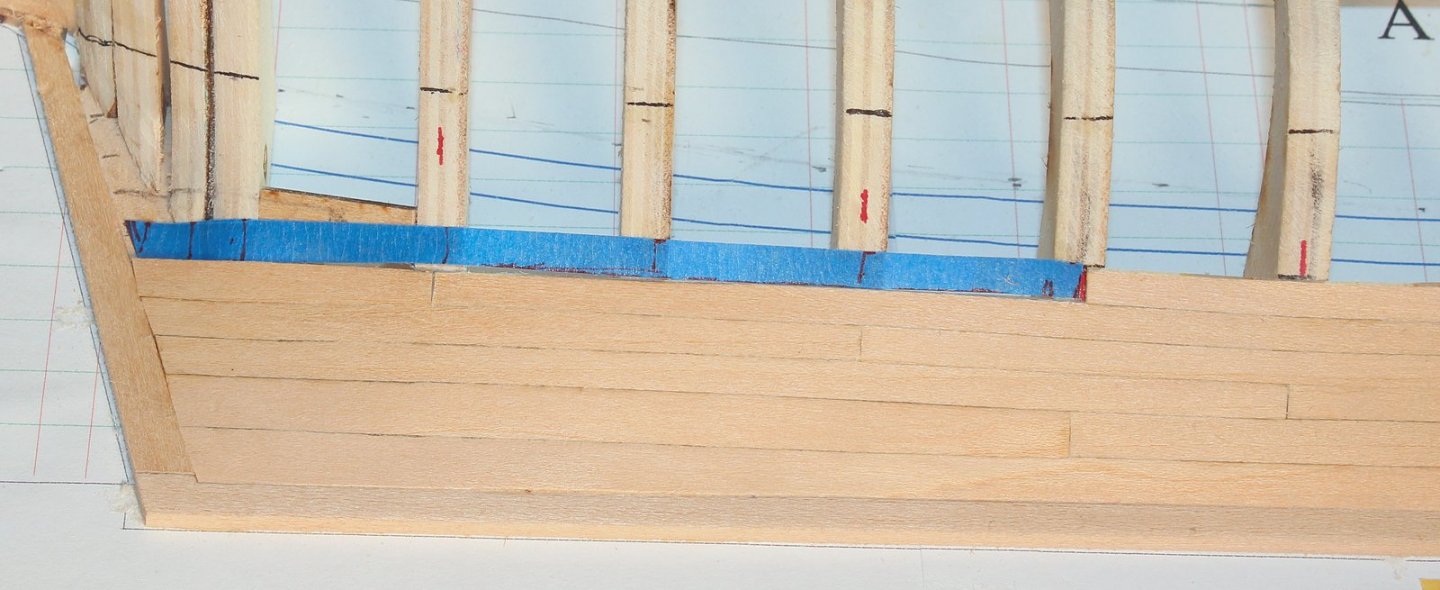
Time to get back to work. The lower two rows of the upper planking belt are installed next. There is nothing special about them. There will be a dropped plank involving the upper two rows at the bow. In the third picture you can see the dropped plank drawn onto the frames. Using tape, the lower edge of the plank was determined by running a pencil line along the top of the plank below and the upper edge was drawn from the marks previously made on the frames. This was repeated for the upper plank and the two tapes are seen below. Notice that I added 1/16" to the fore end of the plank to allow it to seat into the rabbet.


- 167 replies
-
- 12
-
-
Forget the gun ports on the plan. I had originally planned on building them out but had to choose between spacing the frames equally apart from each other or incorporating gun ports. Equal spacing won out because it made the butt shift easier to deal with. Also, if you put in the ports it allows you to look into the hull as there would not have been any covers fitted to these ports. There are a lot of things you can do with the hull once it has been planked including trunneling the hull, installing the ceiling, deck beams/planking, gun ports, hatch covers, etc. I stopped where I did because I wanted to focus on hull planking for the beginner.
-
Just a quick update. I have the hull completed up to main deck cap rail. Unfortunately, I am having computer issues and will not be able to post any pictures until my new computer arrives later this week.
-
I am not a great photographer. One of the things that I find indispensable is photo editing software. It compensates for a lot of sins. It does not need to be expensive but should allow you to adjust light and color, crop, erase and resize. I use an ancient version of Photoshp PSE 9. You could probably find some freeware that would serve your needs.
-
At this point I am going to install the wale, or at least part of it. For ease of bending this will be made up of two laminations of the same thickness as the planking. This technique has the added advantage of using the second layer to disguise any slight gaps between the first layer of the wale and the upper row of hull planking. The wale will be made up of two planks. The first layer will have a butt joint located at the dead flat frame. The location of the wale had already been drawn onto the frames and this was transferred to the tape. I will be putting a scarf joint in the outer layer and its general location is also seen on the tape. The scarf does not need to rest on a frame since it will have a solid piece of wood underneath it. Take a look at the end of the wale. It does not rise above the counter. There is a smooth line connecting the ends of the planks of the upper belt with the end of the wale. Cut out the two pieces of the wale. Save the tape to reuse for the second layer. The wale will be a contrasting color. I have chosen to "paint" the wale with archival marker. The sides of the planks have been painted, even though they will not be seen.

- 167 replies
-
- 13
-
-
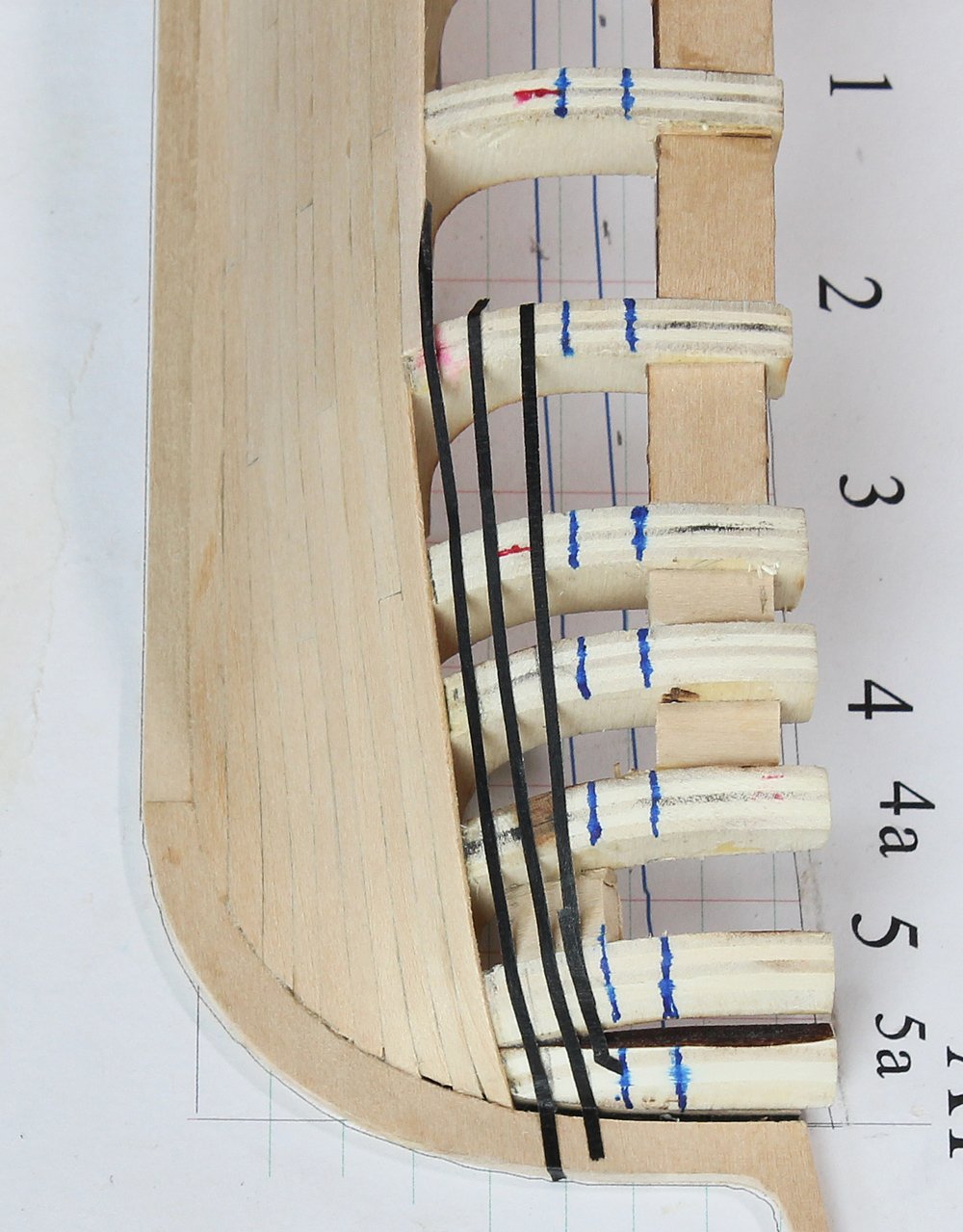
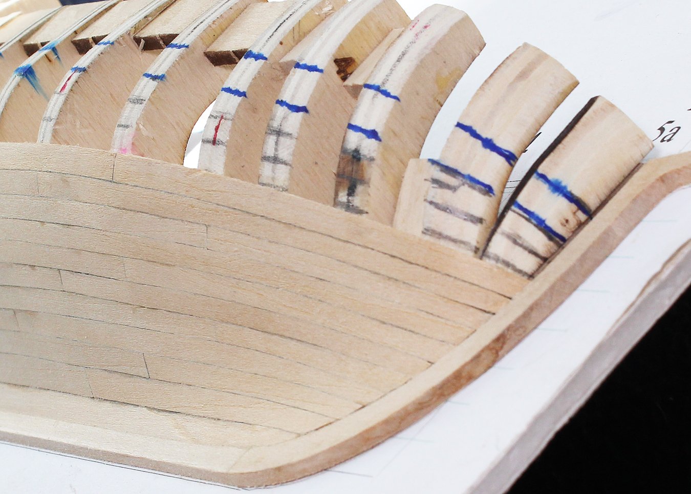
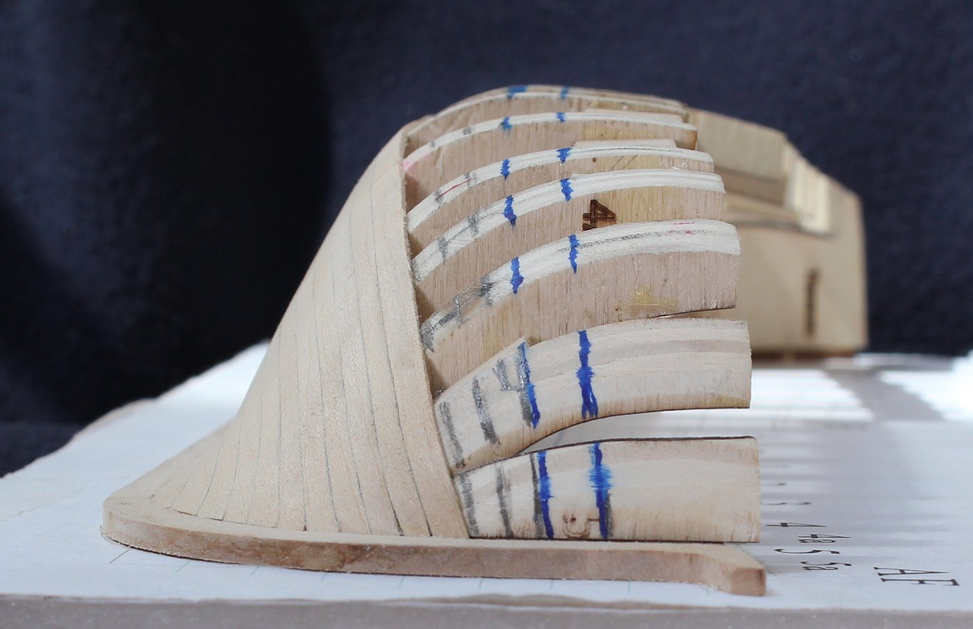
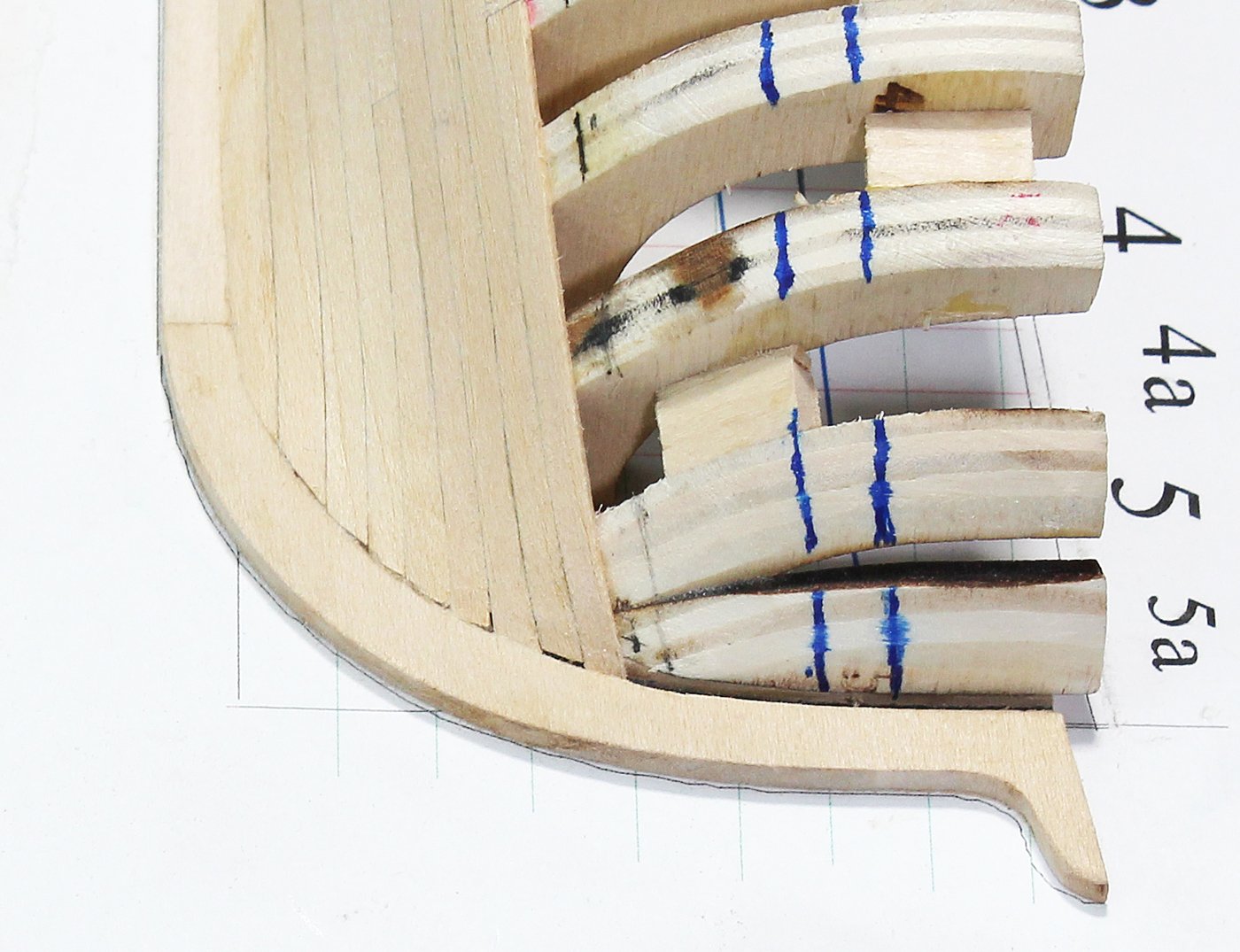
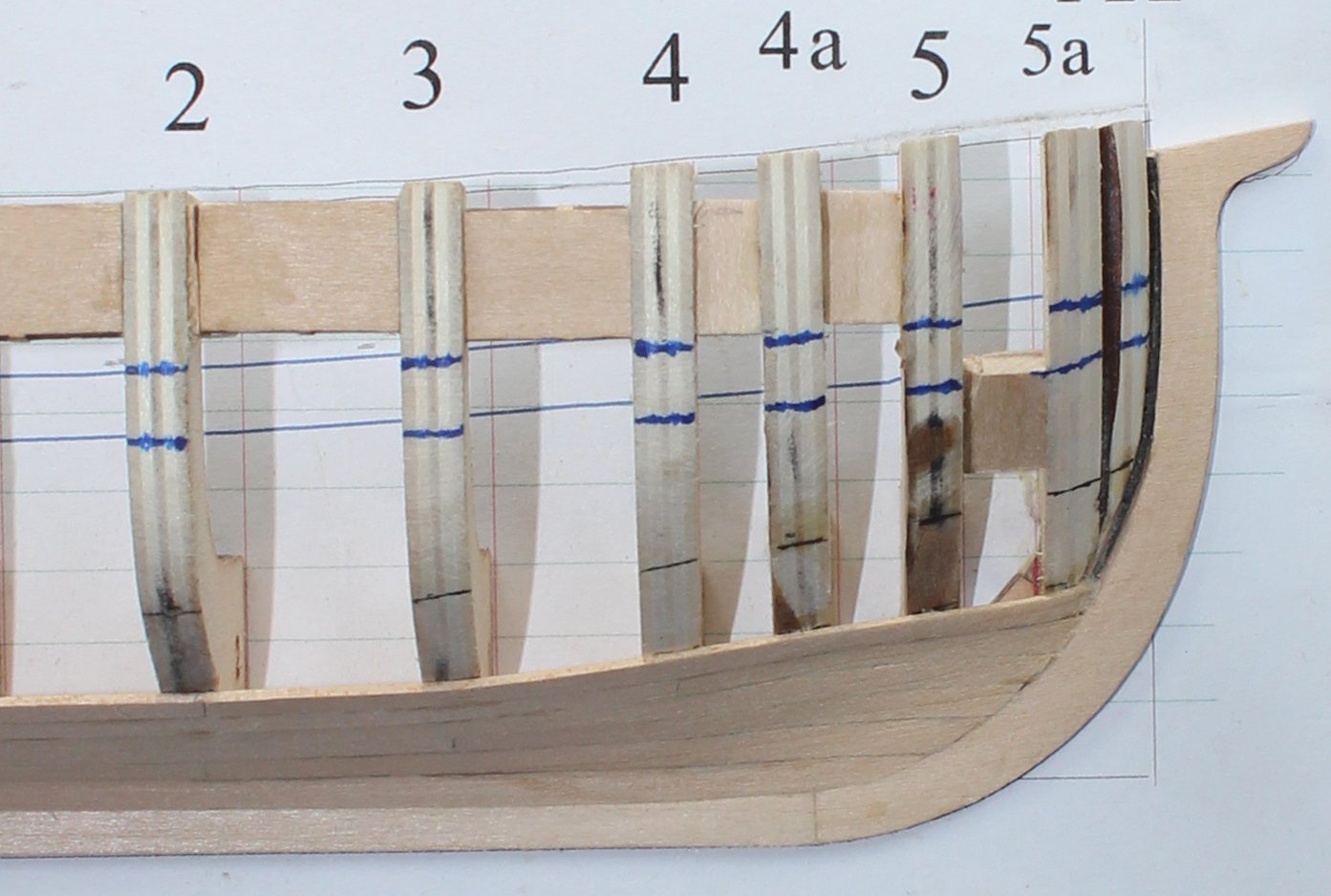
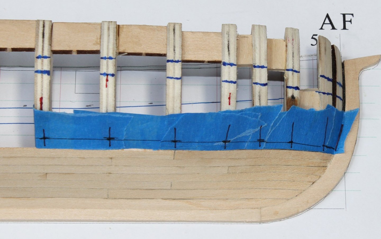
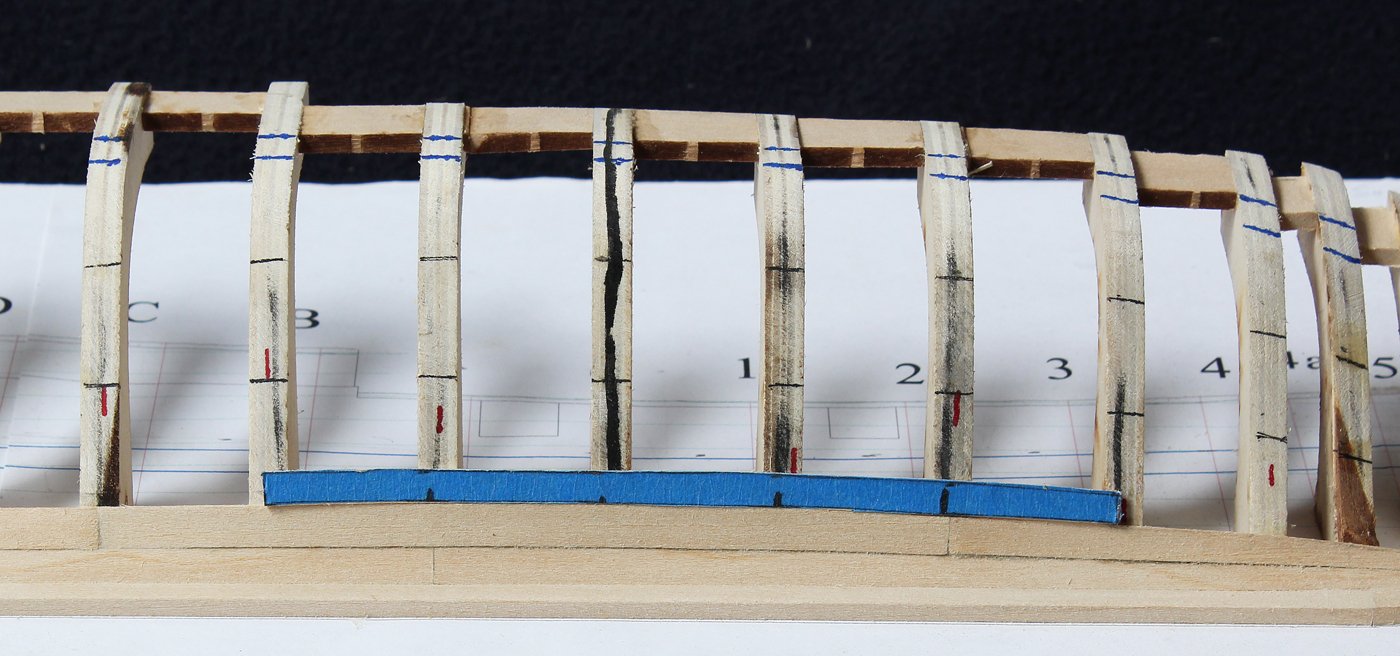
The lower two planking belts have been completed. The next two rows of planking are no different than any of the other recent rows except that the aft ends terminate on the counter. Before going any further, I wanted to finalize the location and shape of the drop plank. As I mentioned earlier, the kit goes through the technique of making a quarter-checked drop plank; this build log will utilize a half-checked. These are always located just below the wale. Using thin strips of tape I have marked out the forward rows of planking, with the drop plank terminating on Frame 5a. After I was happy with the alignment, I drew the planking rows onto the frames. Because of the multiple curves, I used small pieces of tape to determine the shape of the fore plank. Transfer the plank width onto the tape from the marks on the frames. You can see that the width of this plank is wider than those in the middle planking belt. I did not carry the middle belt high enough in front of Frame 2, causing this to occur. If this was a "real" model I would have re-planked the middle belt. But this hull will be joining its four siblings in a closet so I have chosen the lazy-person's way out and left it alone. The curve into the counter is actually very gentle and requires only a little encouragement to fit against the aft bulkheads.


- 167 replies
-
- 11
-
-
Although they are not the best pictures, there are some photos of the bow and stern in my build log that might be helpful.
-
I cannot help you with the HTML stuff, sorry. Your pictures are OK. What do you use for photo software? Securing the subdeck will help correct the warp but I would suggest adding some temporary battens along each side as well. They can be removed as you start your first planking layer. On a kit like this, the rabbet will be simply a bevel sanded onto the edges of the keel piece and the backbone. It will help secure that first layer of planking but will have no impact on the veneer layer. It should be easy to do. The carbide drill bits you are using are extremely brittle, which is why they broke so easily. Get some HSS bits instead. Most of us only use the carbide bits in a drill press because they are so brittle. The type of Dremel you are using complicates things because you are holding it with a pistol grip rather than just grabbing it in your hand. This makes holding the Dremel perfectly still difficult. I had one...emphasis on the word had. Since you appear willing to spend a little money, I would suggest that you get a good quality pin vise for those tight spots and a straight moto-tool (either corded or not).
- 195 replies
-
- 2
-
-
- enterprise
- constructo
- (and 1 more)
-
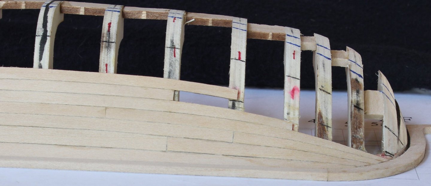
Thank you to all the NRG members who attended the Conference in New Bedford. It was great seeing both old friends and new faces. Work has resumed on the half hull project. There are no complicated planks in the rest of the middle planking belt except for the aft plank in the top row. The pictures show the general sweep of the planking followed by the appearance of the planks at the bow and stern. The aft plank of the fourth row lands on both the counter and the sternpost. If you make a tape template it should not cause too much of a problem. At the Conference several people asked my how I bend my planks. The soft basswood only needs a little water to get it to bend. I will typically clamp it in place, putting a scrap between the clamp and the plank to prevent dimpling. After it has dried (no less than an hour) glue it to the hull. With hardwoods this is more of a problem, sometimes requiring heat and moisture. Never soak a plank in ammonia; it disrupts the wood fibers. The photo shows the curve of the planking without any high or low spots.


- 167 replies
-
- 15
-
-
Post a build log. We are here to help, not criticize. We are also good cheerleaders and teachers when the journey gets tough (and it will). Your best tool will be patience. Your second best tool will be solvent for your glue! We all started at the beginning. We all make mistakes, no matter how many years we have been building models. On my current project (see below) I ripped out three rows of planking, costing me several days of work. Just remember, this is a hobby... Have fun with it; and if you learn something along the way even better.
-
Thanks, Paul. I will be back to work on her later this week.
-
The 2019 Conference is over and I would like to thank all of the speakers and especially the members who joined us in New Bedford. For those who could not join us, you missed a fantastic group of fellow modelers and preeminent speakers. Hopefully we will see you next time.
-
Fairing the bulwarks
tlevine replied to Bill Madison's topic in Building, Framing, Planking and plating a ships hull and deck
Don't you mean bulkheads? There are numerous build logs for this kit. Several of them discuss how to fair (sand) the bulkheads. Just type "armed longboat" in the search bar. -
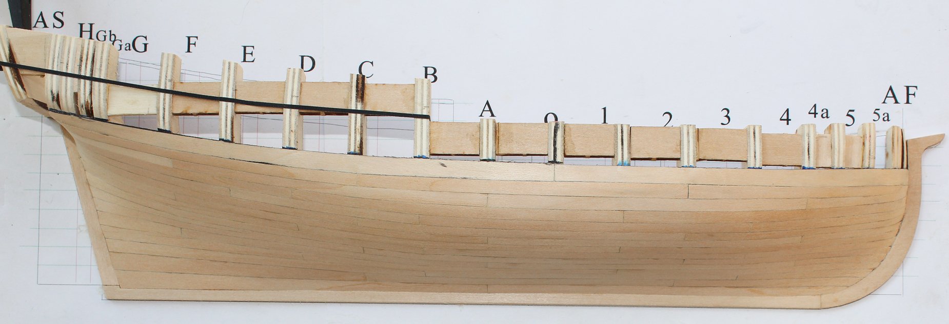
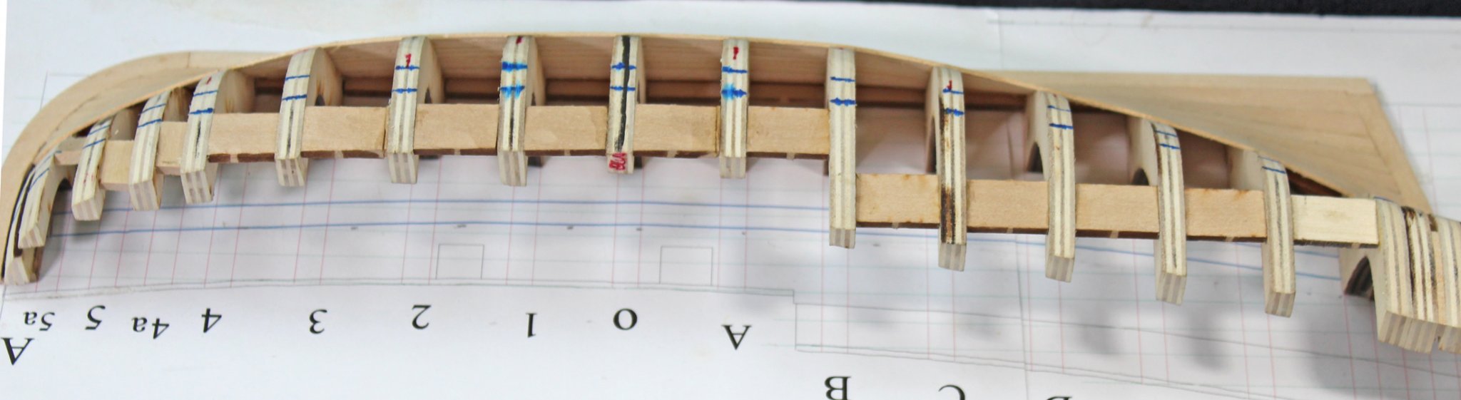
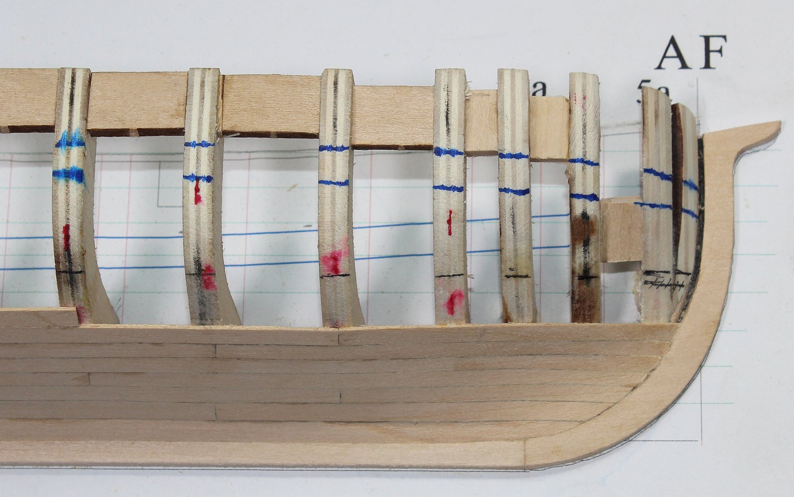
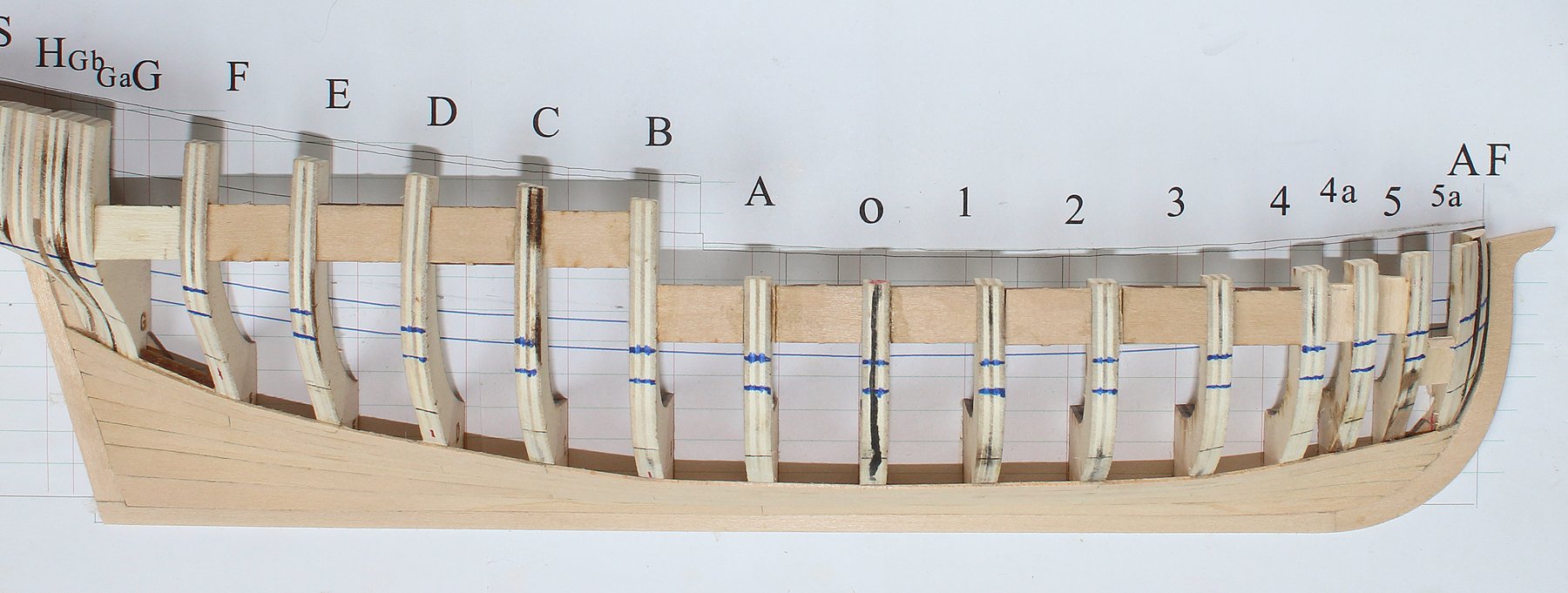
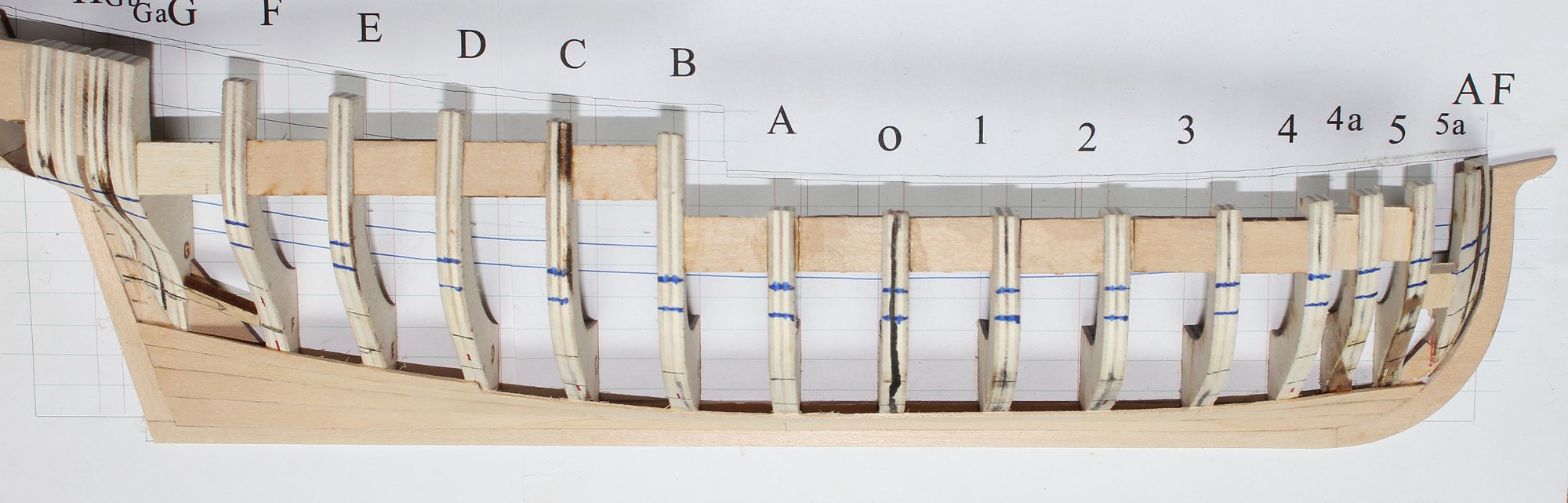
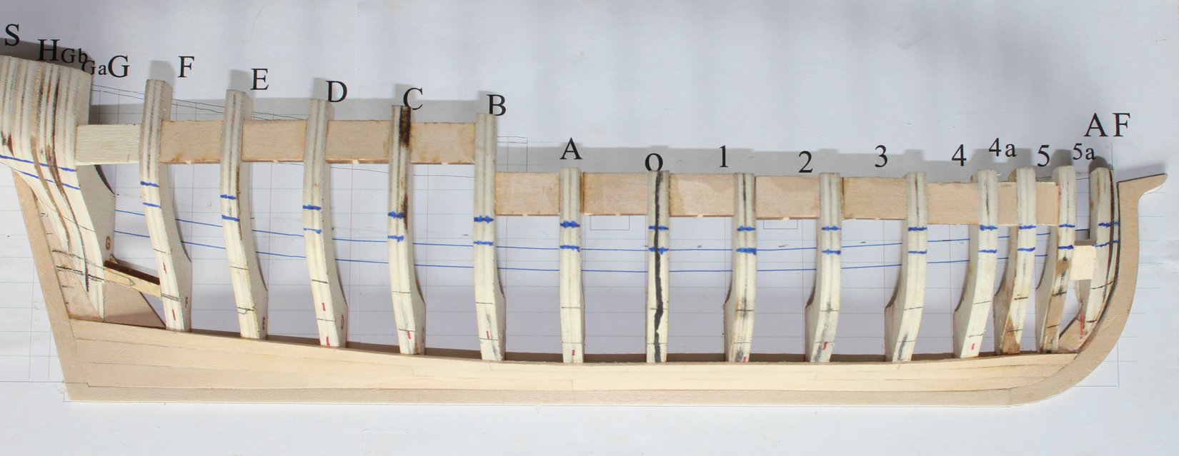
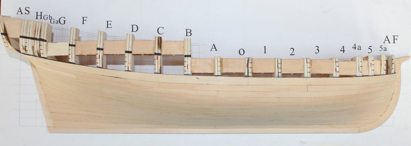
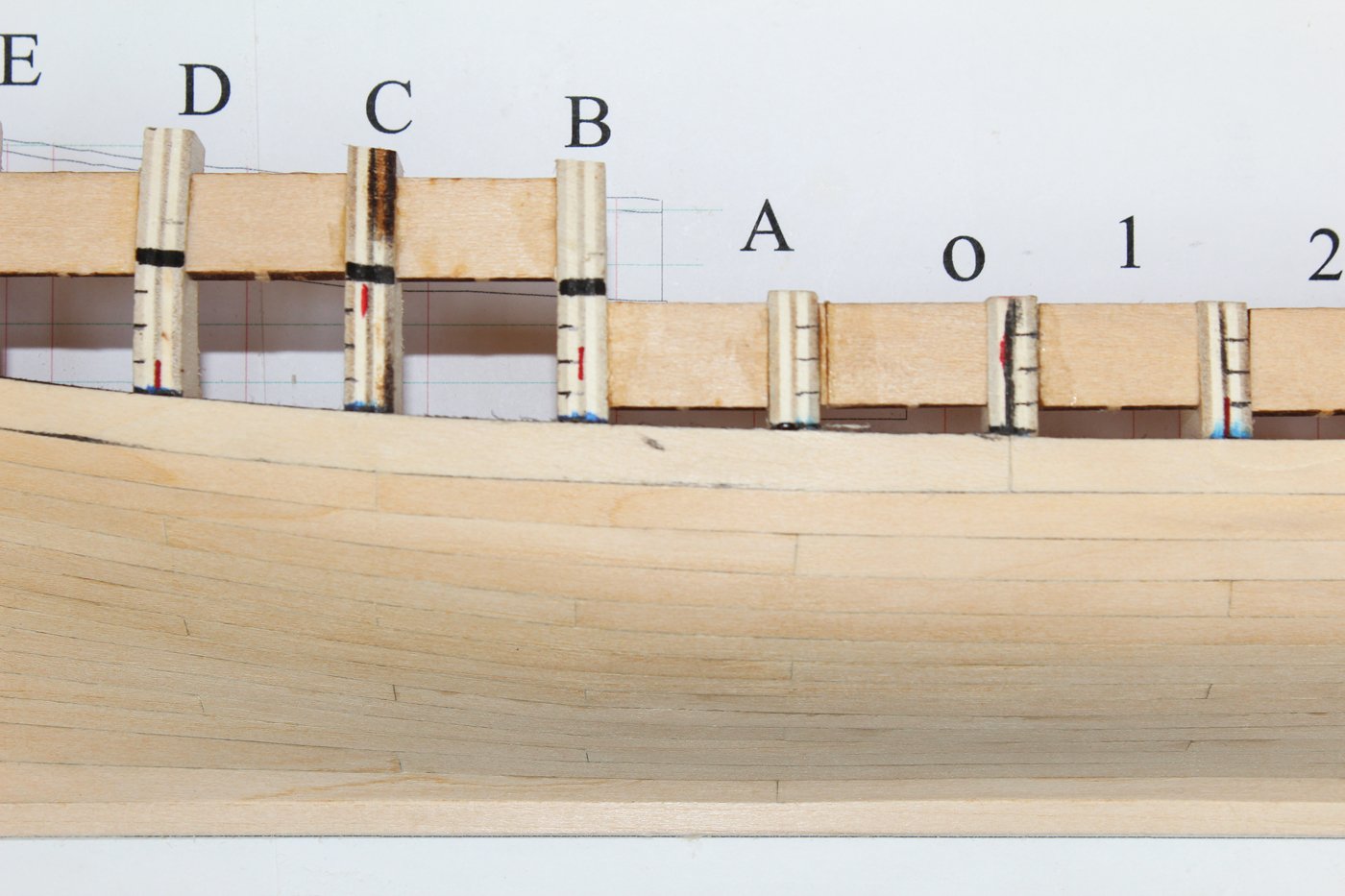
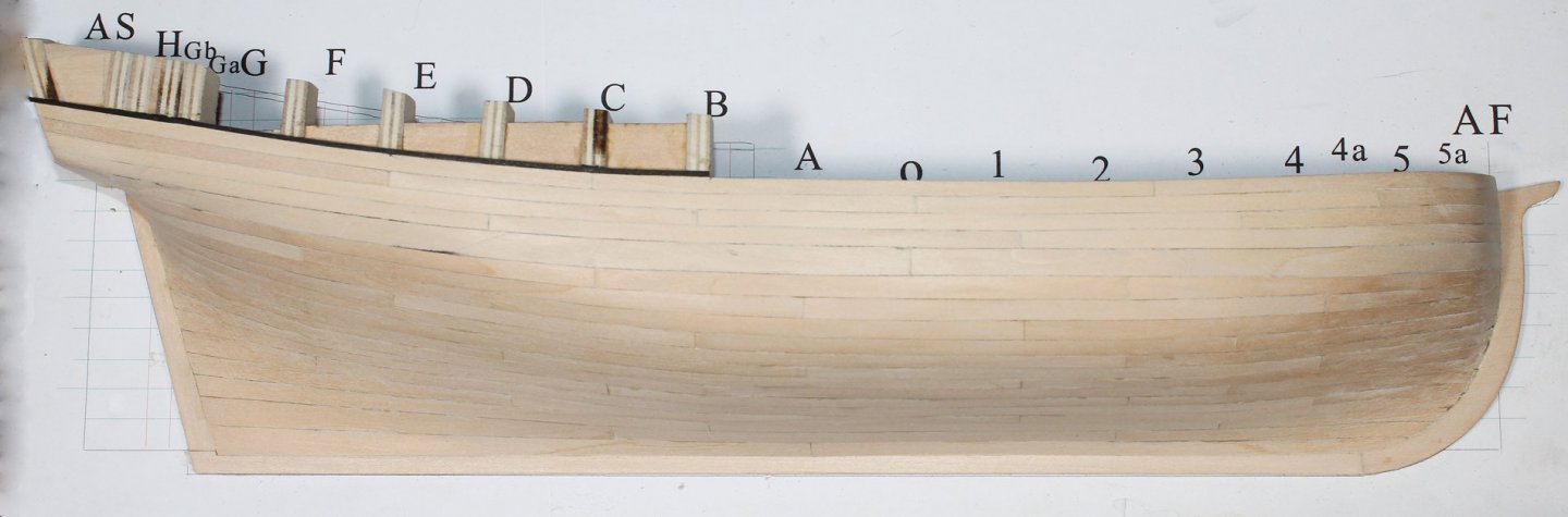
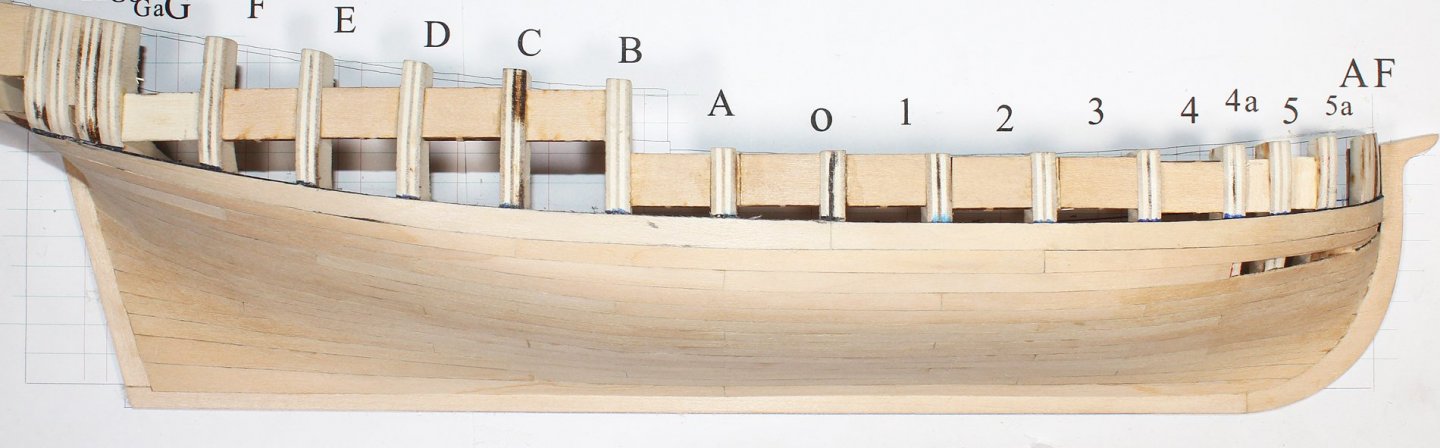
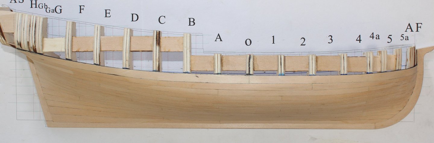
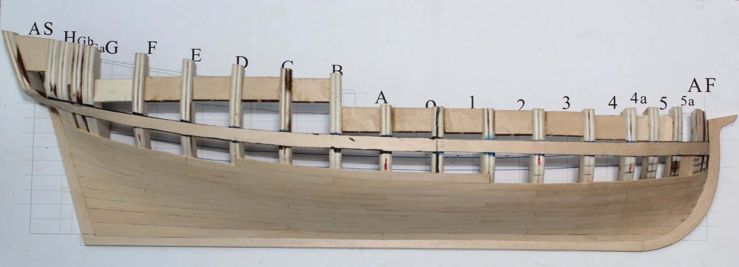
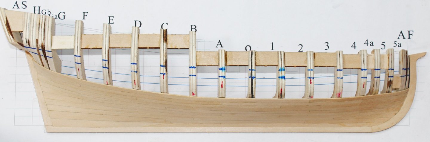
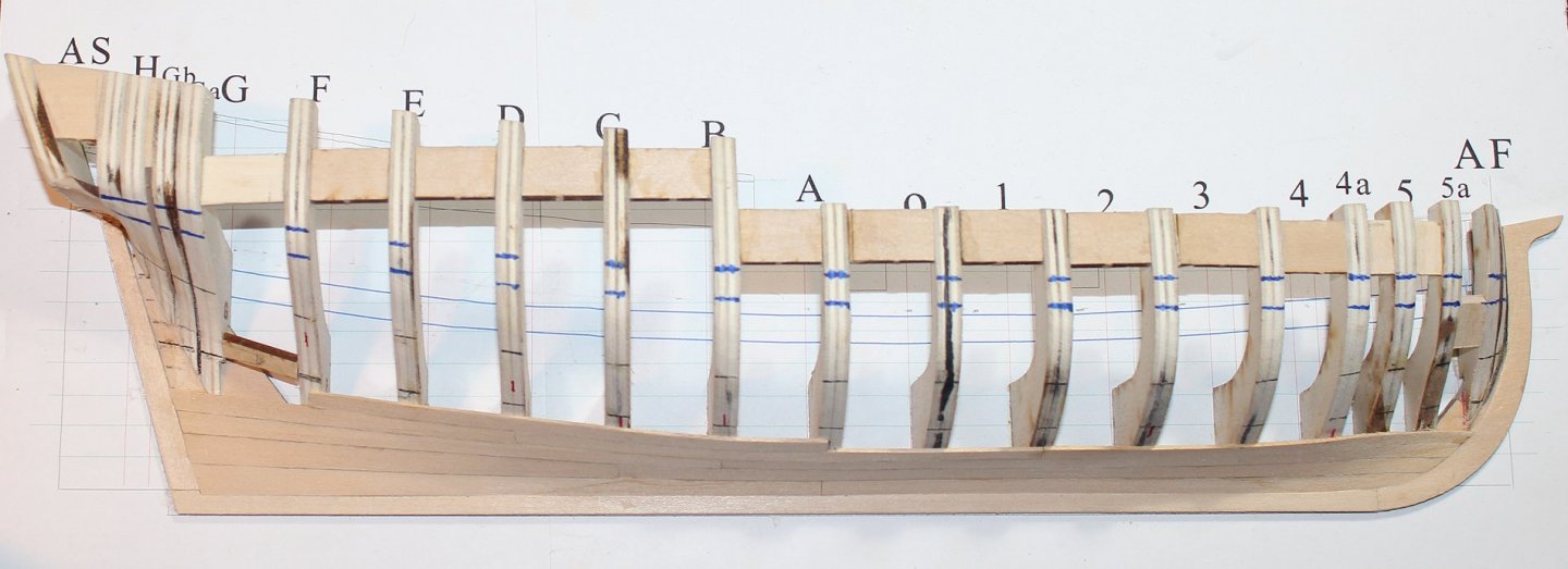
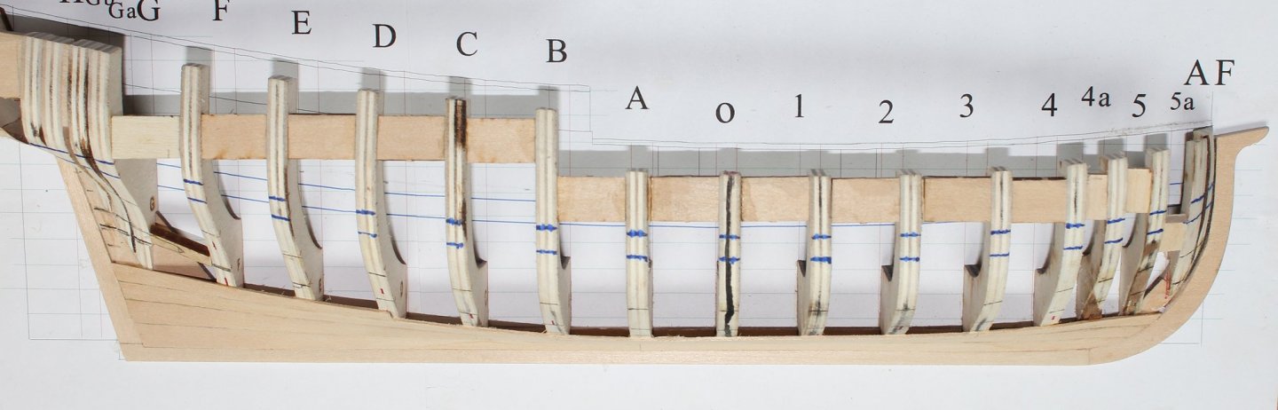
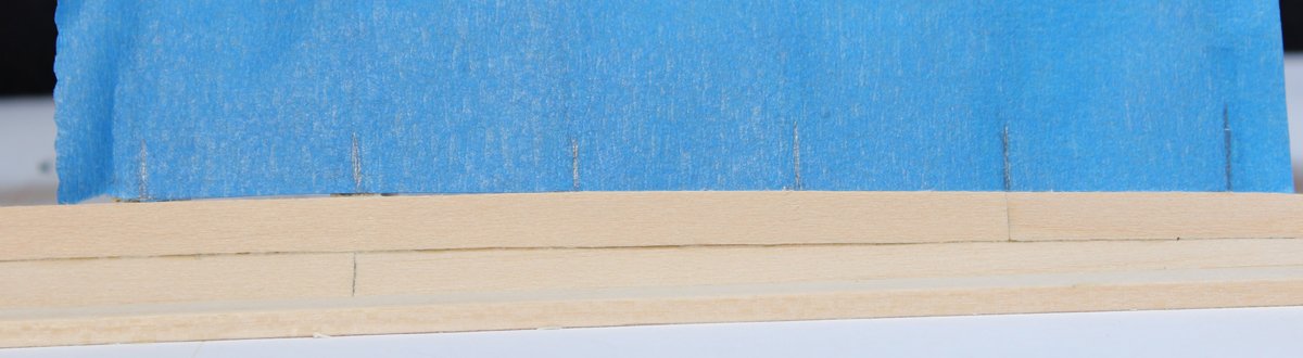
Ignore them. They were designed to give the builder and idea where the planking belts run. But each time I made the hull, the locations were just a little bit different. The lower two marks are fore the garboard and broad strake. The top two marks are the upper and lower borders of the wale. The vertical line next to the "A" is the thickness of the backbone assembly.
-
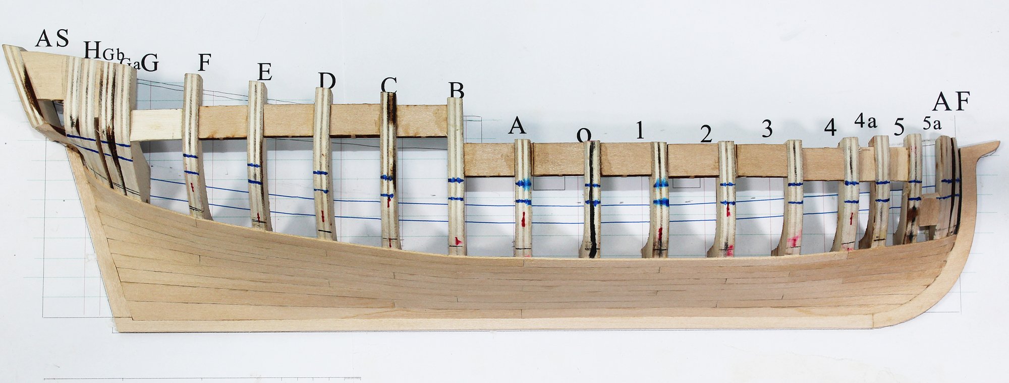
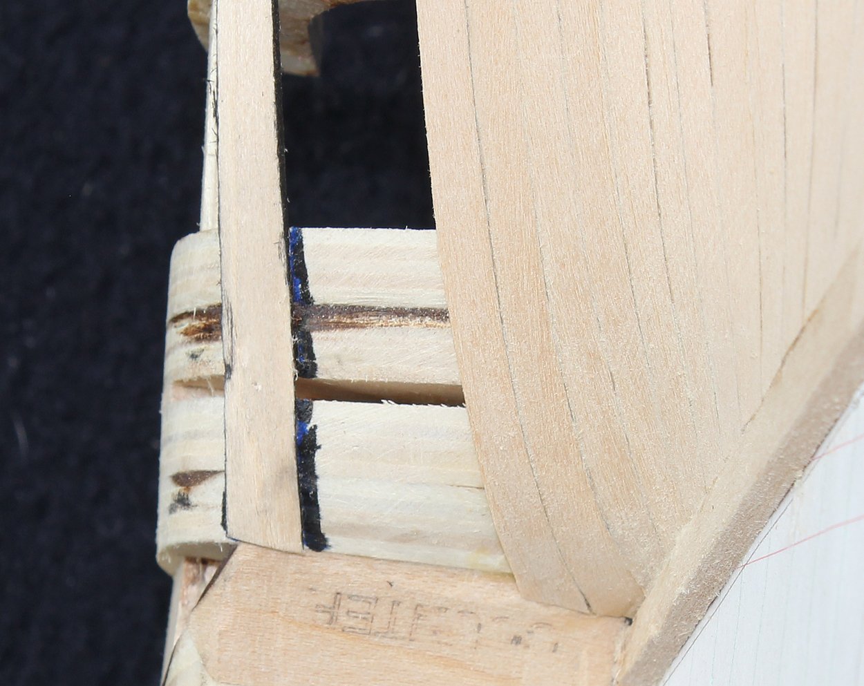
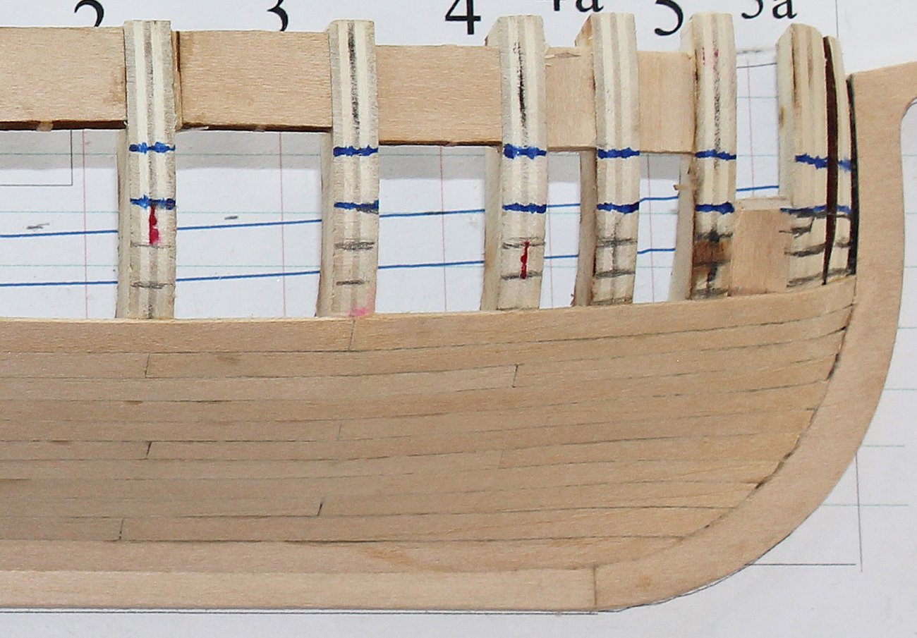
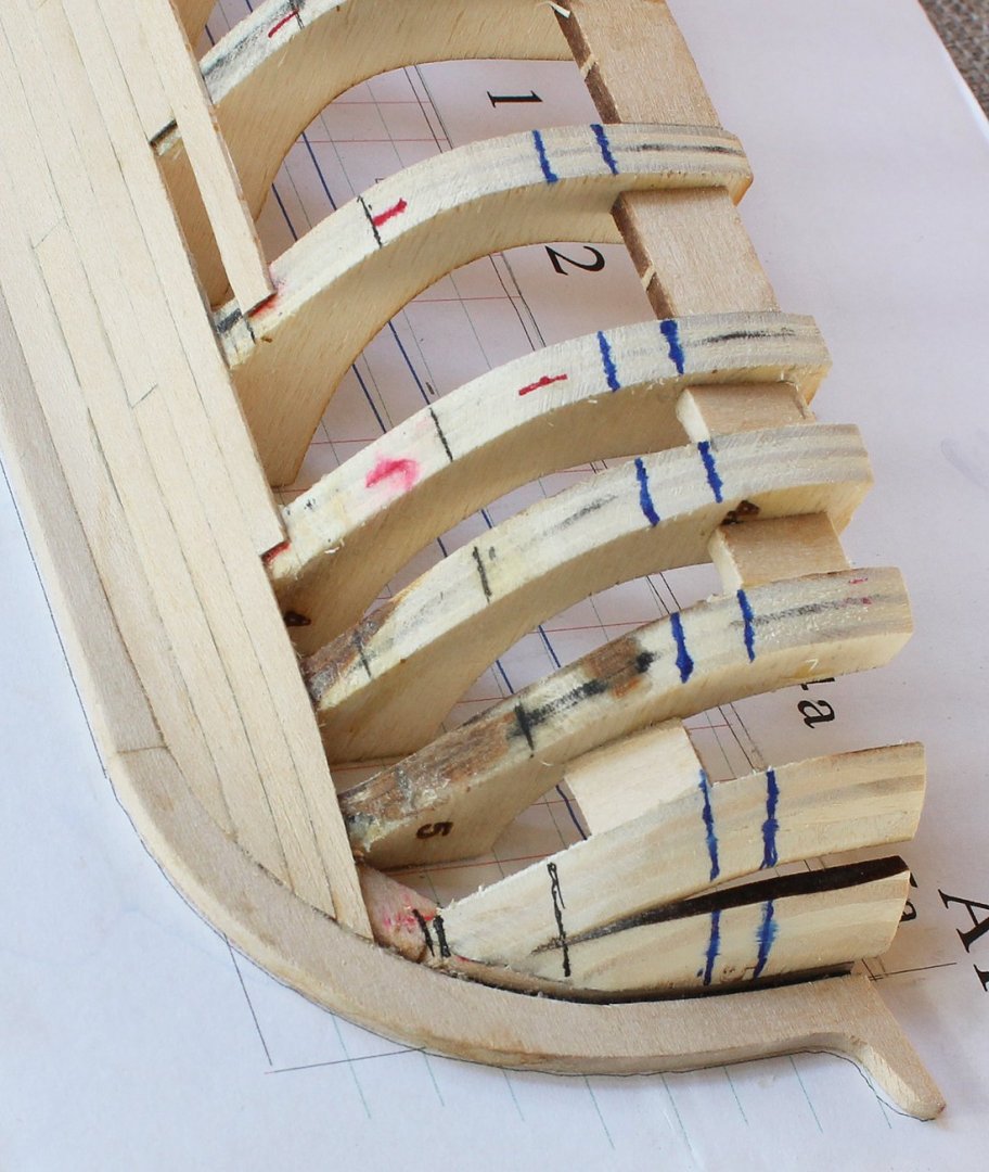
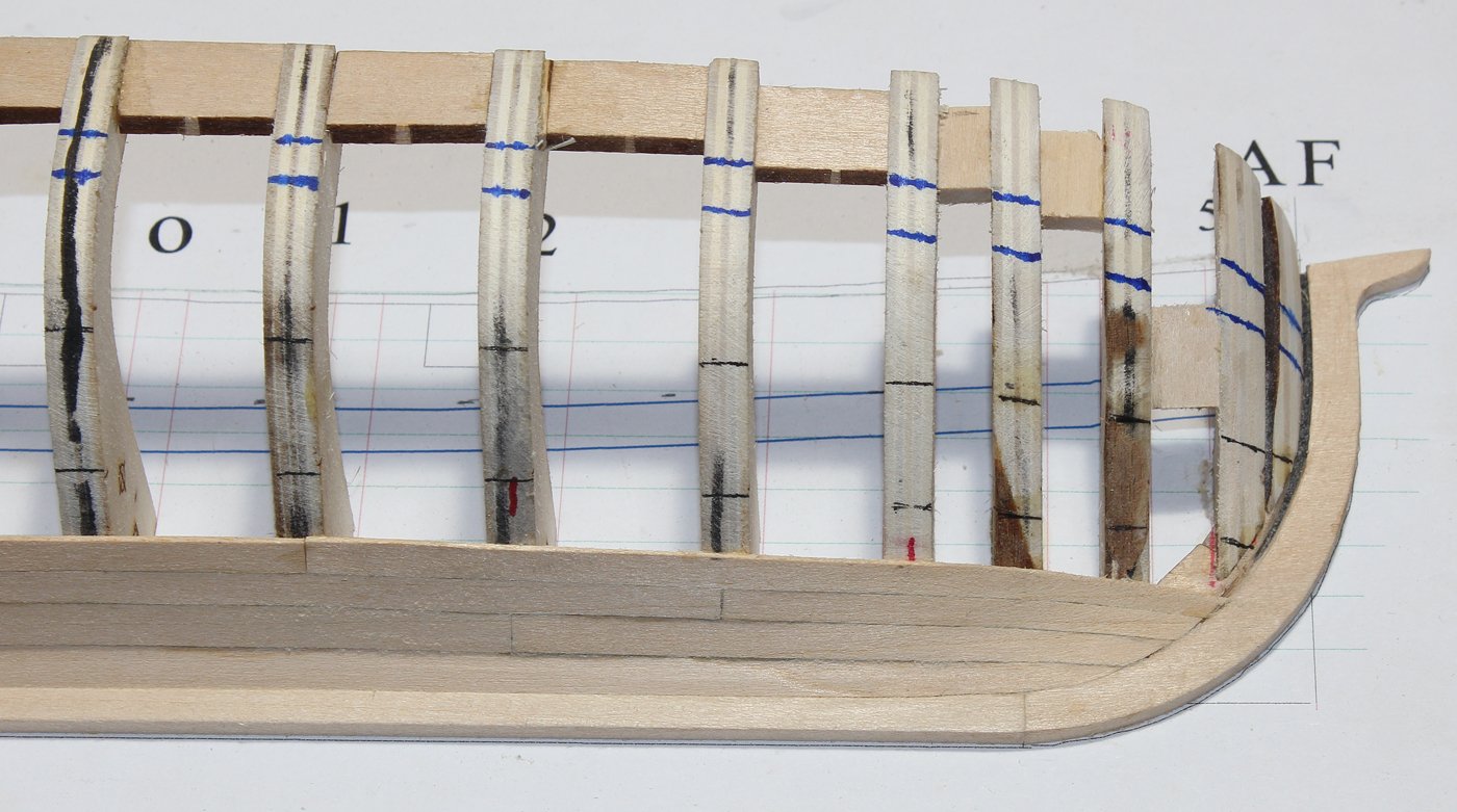
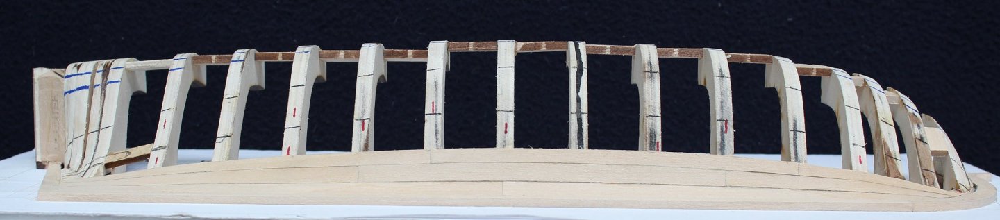
This kit is designed as a teaching aid. IMHO, the best teaching aid also teaches the teacher. And this one reminded me that photographs will often find errors that the eye will not. So even if you have no intention of posting your pictures, they can be very helpful modeling aids. Look at the above picture. You can just barely see that there is a concavity in the planking at Frame 5. This was a lot more obvious in the picture than in real life. Looking more carefully, the problem is not that Frame 5 was sanded down too much. Instead, I did not sand Frame 5a enough. My only option was to remove the involved planking and reshape Frame 5a. The smudged ink is because I used a lot of isopropanol to dissolve the glue. When you find it necessary to remove planks, do not even attempt to reuse them. It will never look right. The result was worth it. The build log is caught up to my construction progress. The NRG conference is next weekend in New Bedford Mass. I will be hosting (hostessing just sounds stupid) a round table on hull planking. Hope to see some of you there. Construction will continue upon my return home.

- 167 replies
-
- 17
-
-
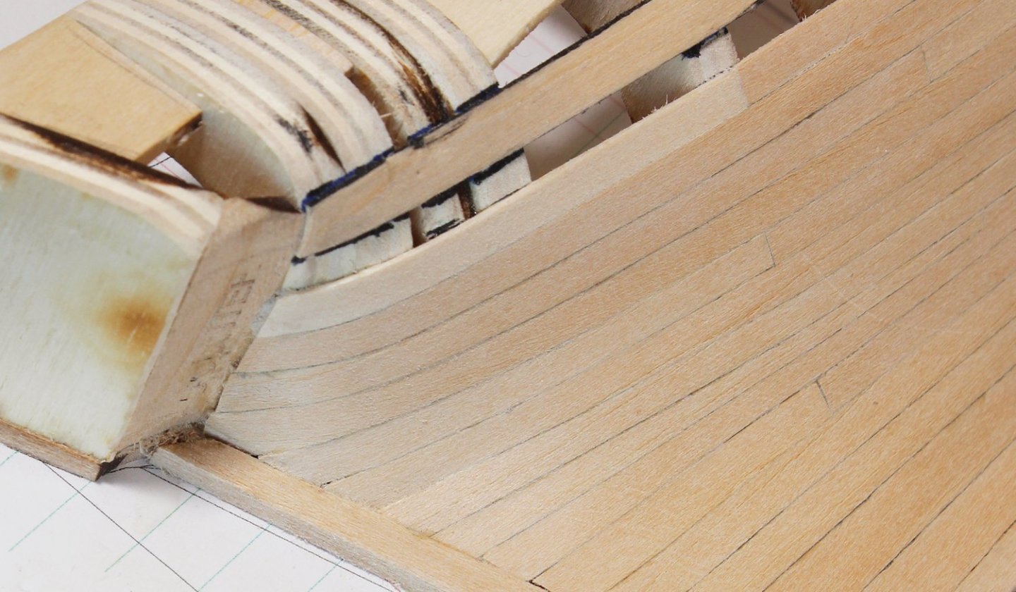
The lower three rows of the middle planking belt are straight forward; there are no other stealers and the dropped plank is located in the upper belt. The aft plank in the top row is complicated by the need to terminate on both the sternpost and the counter. The photo below shows the plank above the stealer installed. I used small pieces of tape to form the template for some of the planks with an extreme curve. This will give a much more accurate template in these areas.

- 167 replies
-
- 11
-
-
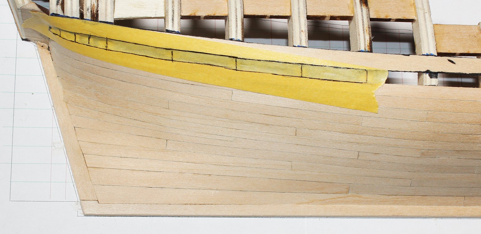
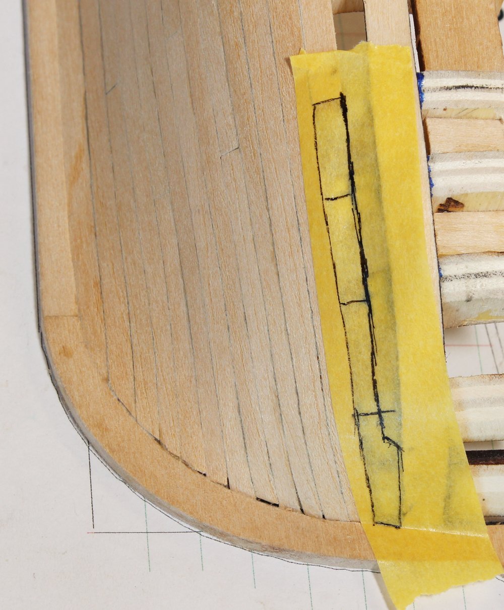
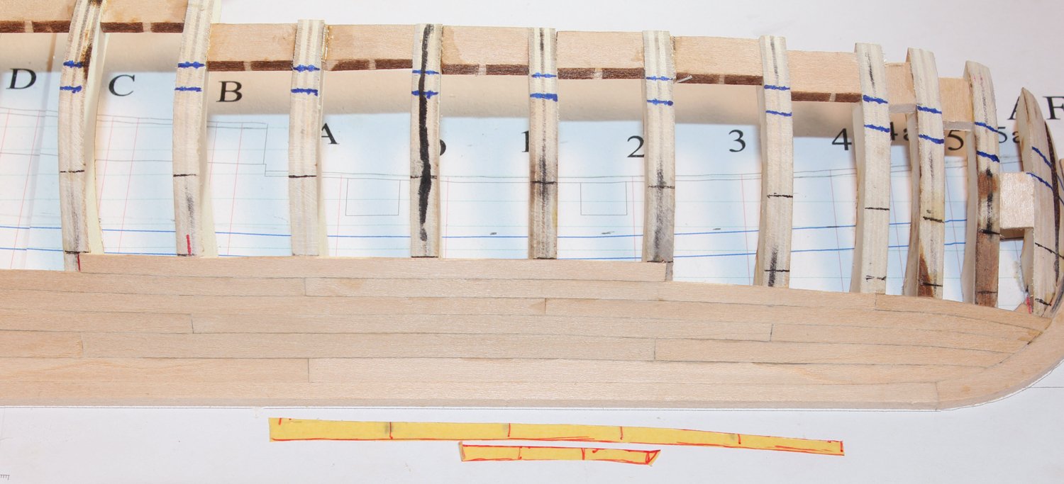
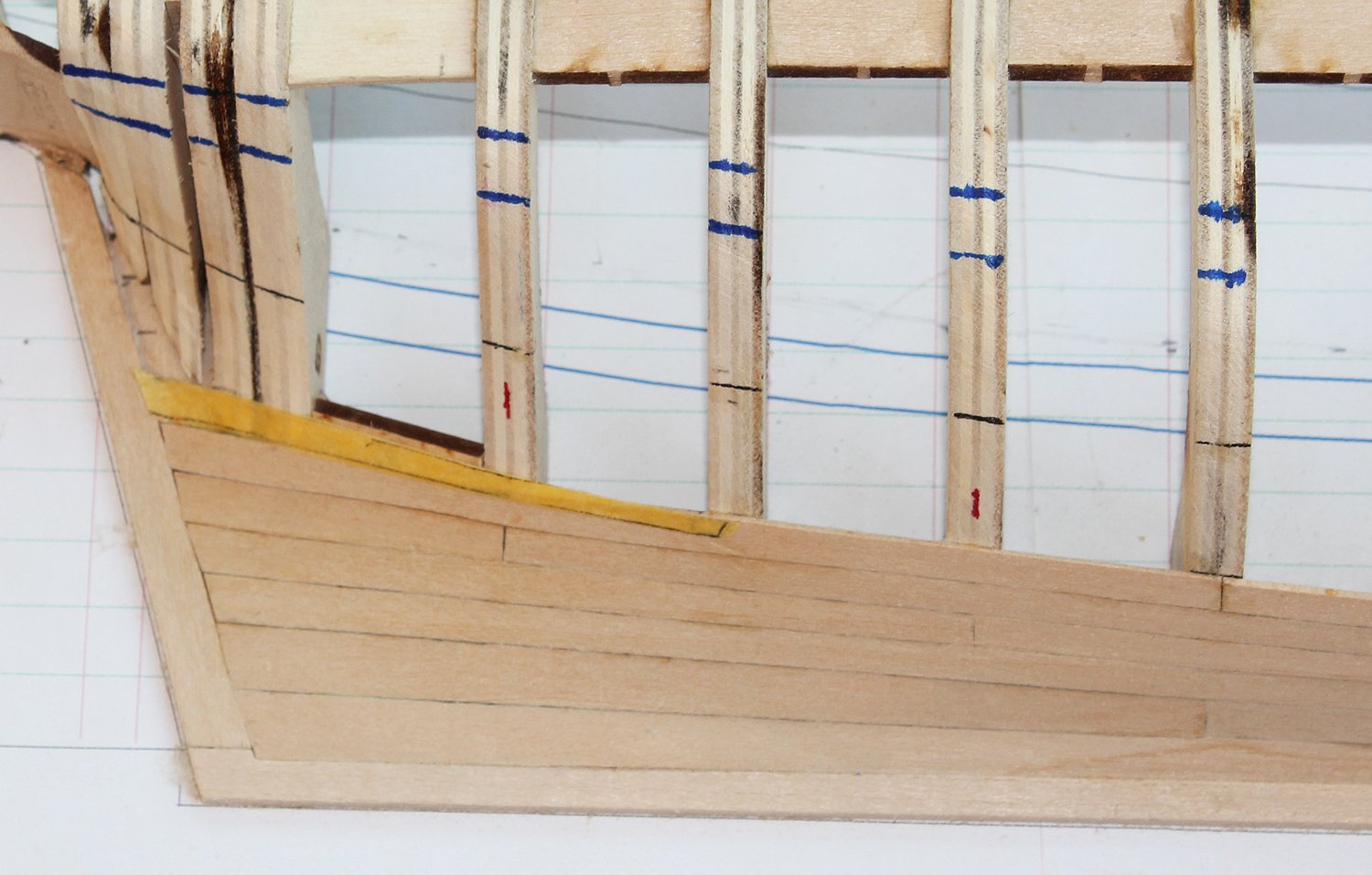
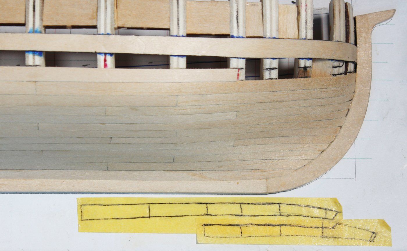
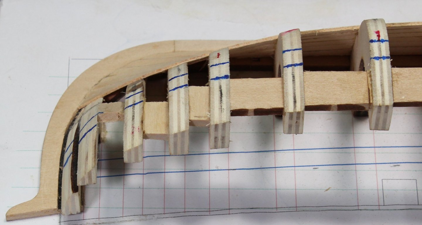
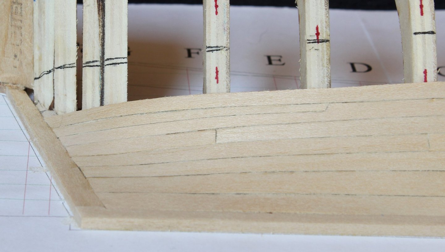
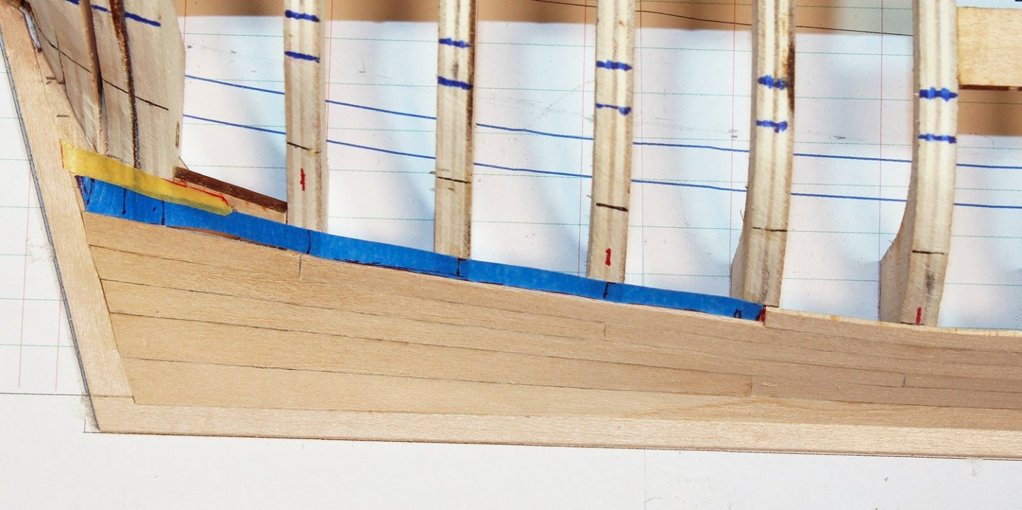
This shows how the planks change shape. The strips of tape are the templates for the middle and fore planks of row 3 of the lower planking belt.In order to continue the appearance of the run of the planks paralleling the wale, the stealer will be placed between the lower and middle planking belts. The forward location of the stealer will be, in part, determined by the location of the neighboring plank butts. The photo below shows the area in question. The previous row has a plank butt on Frame F and the planks two row either side have butts on Frame D. You can still see the pencil lines for the quarter-checked (on the filler piece) and the half-checked stealers. The first step is to make the aft plank which will be stolen from. Don't waste too much time finalizing the width of the plank aft of Frame F because of the stealer. The yellow tape in the next two photos shows the shape and location of both a half-checked and quarter-checked stealer. You can see that the width of the stealer at the sternpost is the same as the width of the other planks and how the upward sweep of the stealer more closely parallels the wale. Make and install the aft plank. I find it easier to cut the stealer into a plank that has already been glued to the hull. I will be installing a half-checked stealer. The kit takes one through installing a quarter-checked stealer. In the picture below you can see that the location for a quarter-checked stealer is not correct. Although the forward extent of the stealer is correct, I would have needed to steepen the angle of the stealer (compare with the photo above). Lay the template for the stealer over the plank, starting on Frame E and ending at the sternpost. Draw the outline of the stealer onto the plank and cut the plank with a straight edge razor. I do not like a #11 blade for this; a razor pressed into the plank will result in a straight line without the need to sand. And here is the final result. Note the smooth transition between the stealer and the plank at Frame E. Here is the lower belt completed with the stealer.


- 167 replies
-
- 12
-
-

-
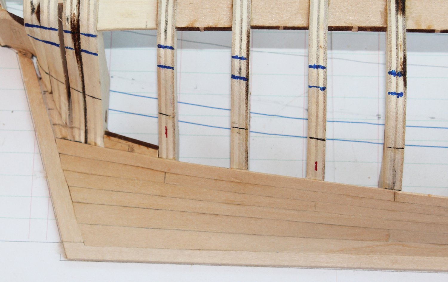
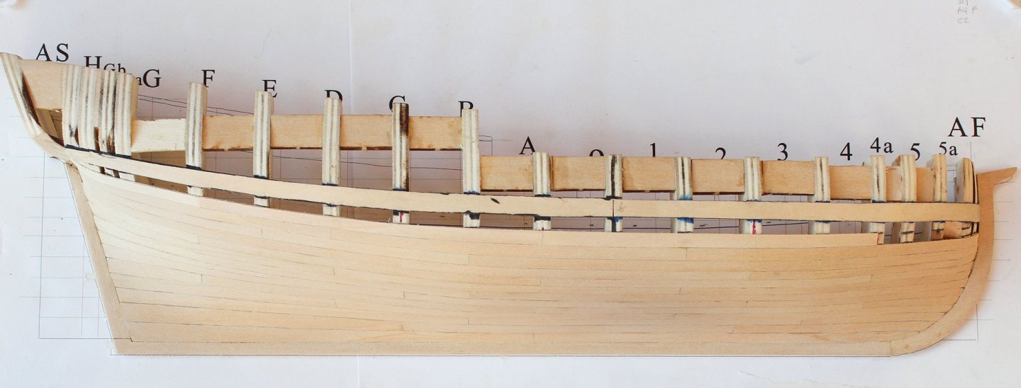
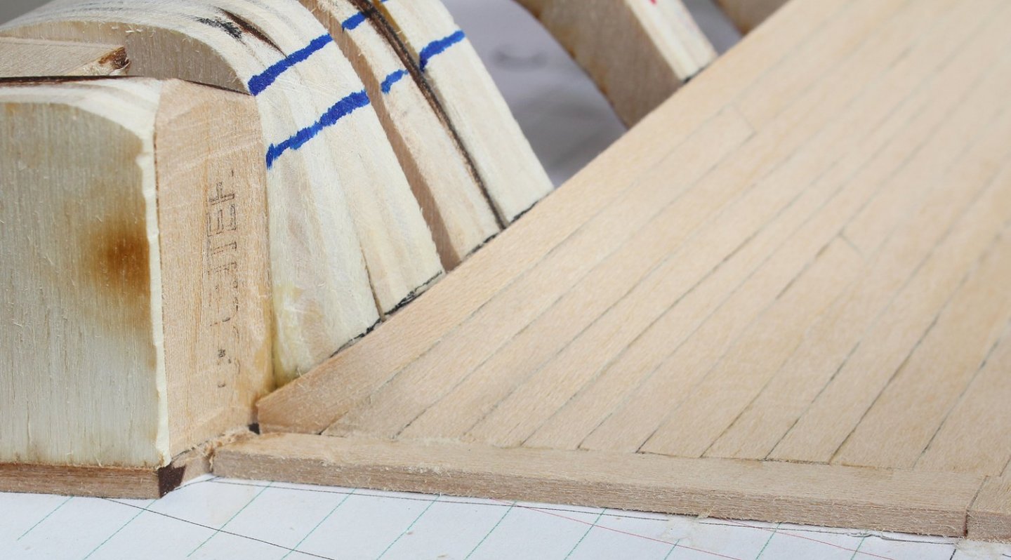
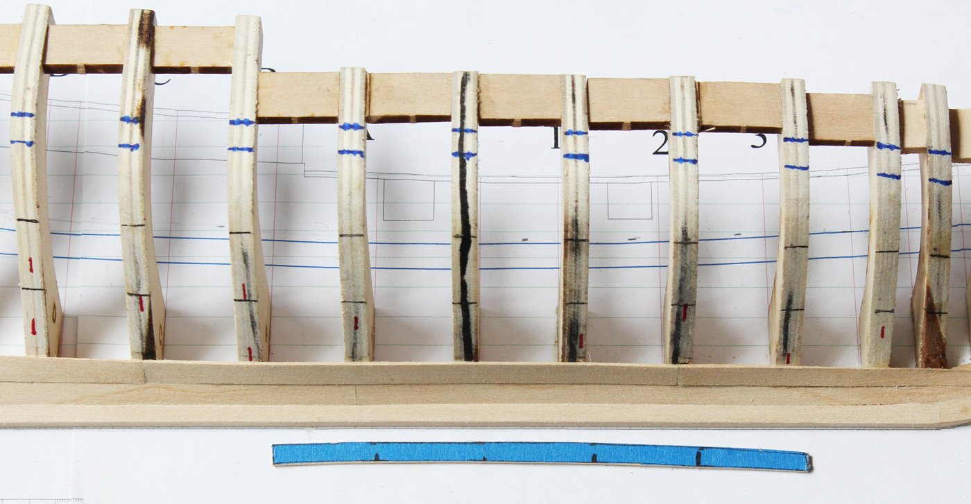
The second row of this planking belt is developed just like the first row. You can see in the picture below how much curvature is developing in the fore plank. Aft, the run of planking continues to parallel the wale.
- 167 replies
-
- 13
-
-
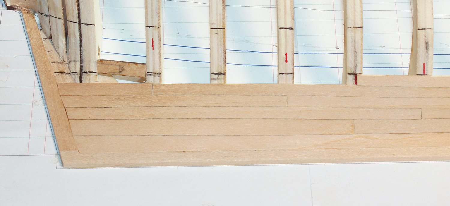
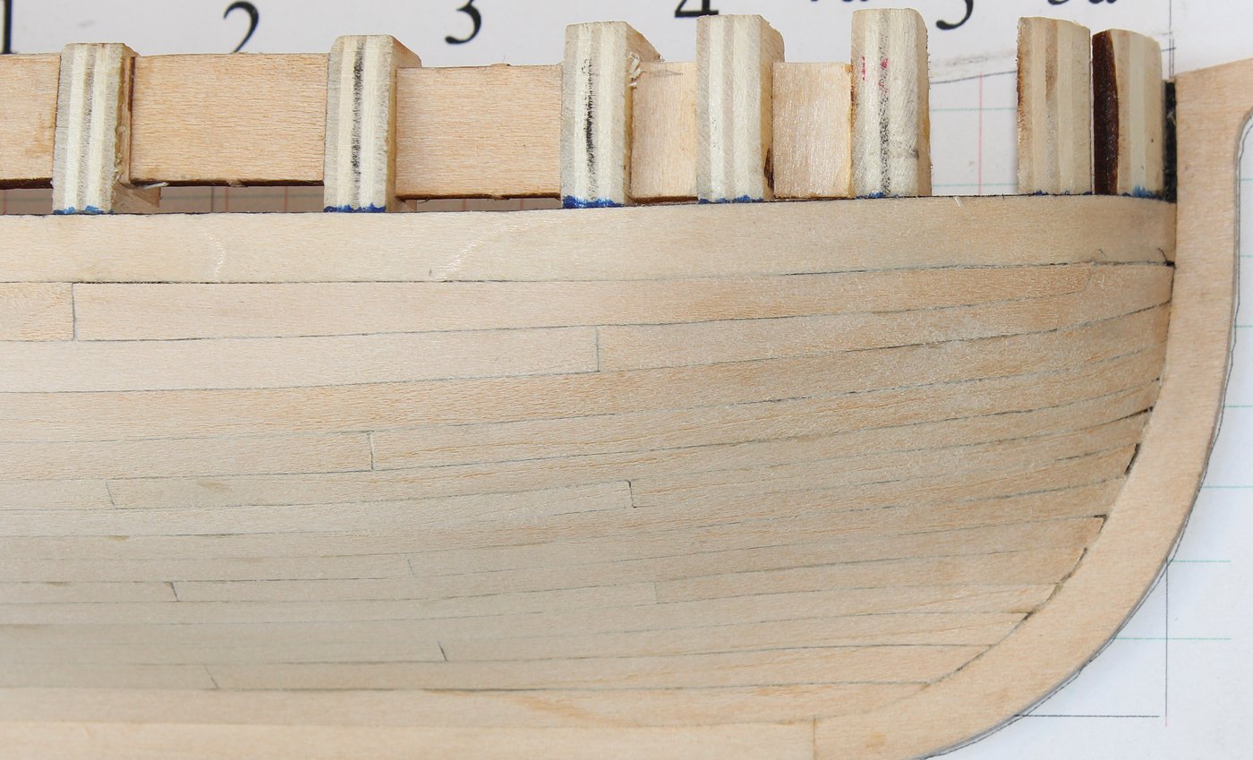
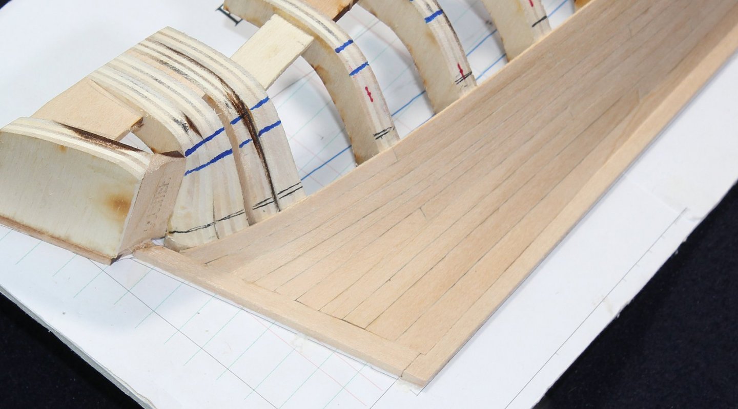
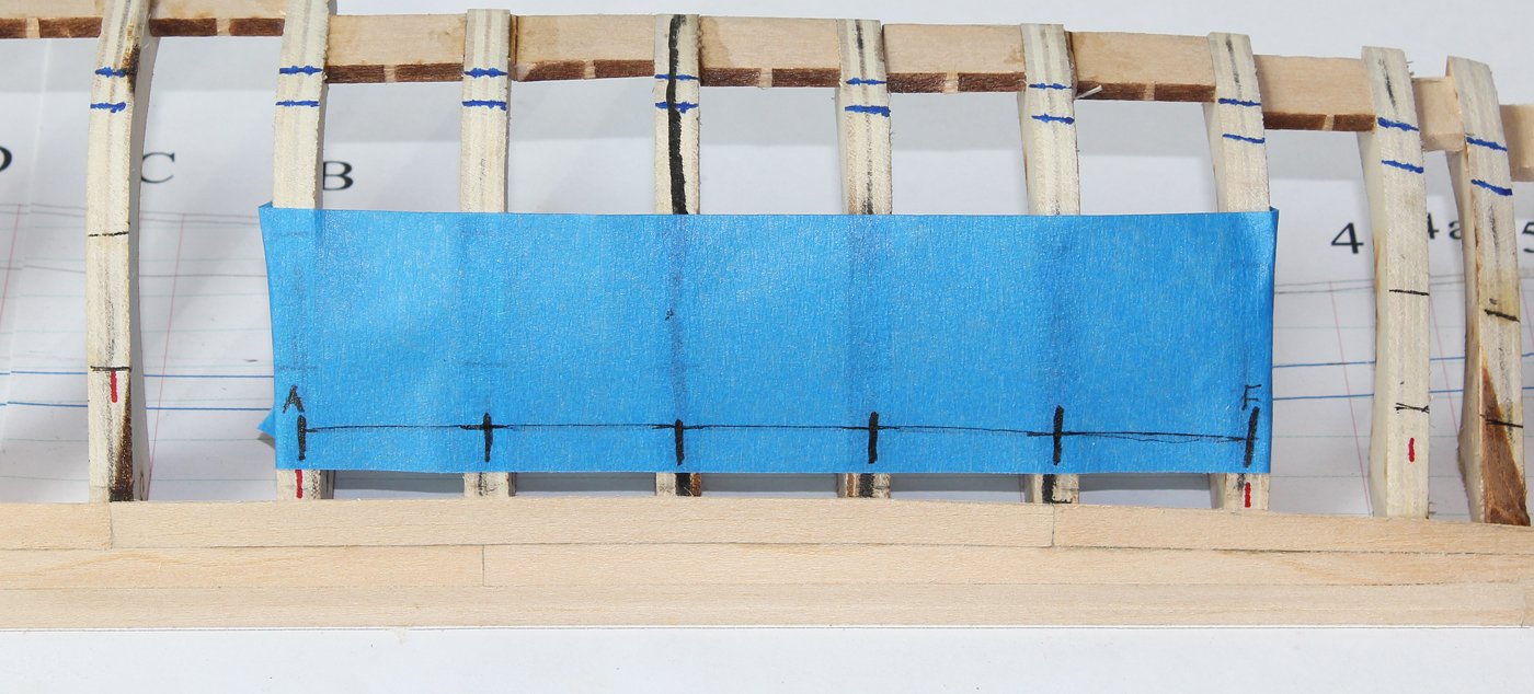
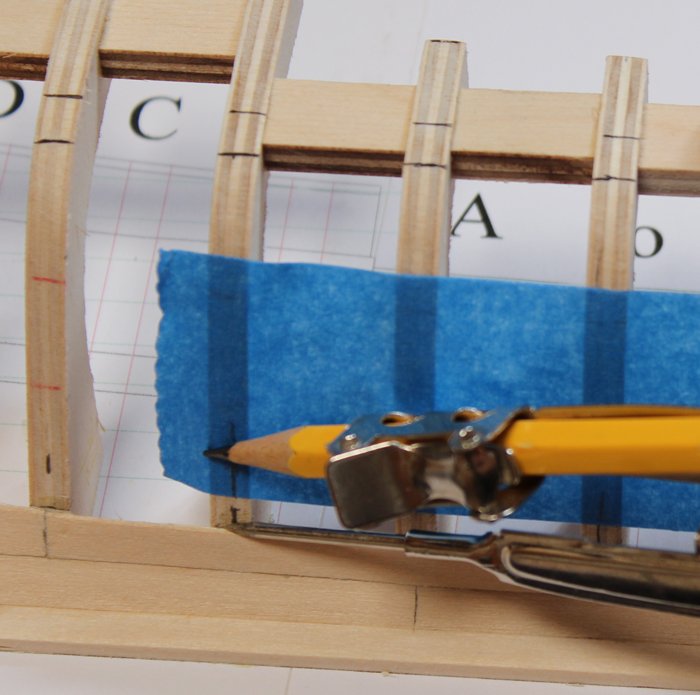
It is time to start planking the belts. There is more than one way to determine the shape of the bottom of the next plank. An alternate approach would be to put a length of tape (or a strip of paper secured with tape) above the broad strake and take a compass to draw the shape onto the tape or paper. Do not forget to locate the frame positions on the tape. Cut off the excess tape and finesse the shape against the broad strake. For my convenience, I have drawn a wide line on the dead flat strake. Using the tic strips mark the upper edge of the plank onto the tape and connect the marks with a ship's curve. Leave the tape wide to prevent distortion and then put it on the planking sheet. Cut out the plank, leaving a little excess on both the top and bottom. Trial fit the plank to the hull. When happy, add the caulking lines and glue in place. Do this for all three of the planks in this row. The result is a smooth curve when seen from both the side and below. Take note of the height of the strake as it enters the bow rabbet: no smiley-face.


- 167 replies
-
- 12
-
-
What about a band saw? There would be less waste cutting billets down to usable thickness than with a table saw.
-
Same problem. However, simply typing pinnace, the first item is a 28 ft. pinnace and by typing longboat, a 20 ft. longboat is halfway down the page.
-
And if you are interested in learning how to plank correctly, consider this:
-
Brian, it is not up on the website yet. Please either call or email the office (both are found here: https://www.thenrg.org/contact-us.php).