tlevine
-
Posts
2,033 -
Joined
-
Last visited
Content Type
Profiles
Forums
Gallery
Events
Everything posted by tlevine
-

Greetings from Tacoma. Have I taken too big a bite?
tlevine replied to Paul Gardner's topic in New member Introductions
Paul, welcome to MSW. This project is designed in such a way that a true novice should not have much problem. The only power tool I used was a Dremel, and even that is not necessary. The following was stolen from Kurt's announcement in the Nautical Research Guild announcement section. We can now take orders for the Half Hull Planking Kit The kit is not yet listed at the NRG Store, and when it is, we will update this, but we can now take orders through the NRG Office. Call the office directly or send an email. See the NRG web site for the phone and email. (Not listed here to thwart robots/spammers) The price is $65.00 for non-NRG members. NRG members get the member’s 20% discount price of $52.00. Prices are plus shipping. US shipping is $15.00. Canada shipping is $20.00. Other non-US shipping is $26.00. Expected shipping is the week of 10-22-19. And if you are lucky, Mary will convince you to join the Guild as well! -
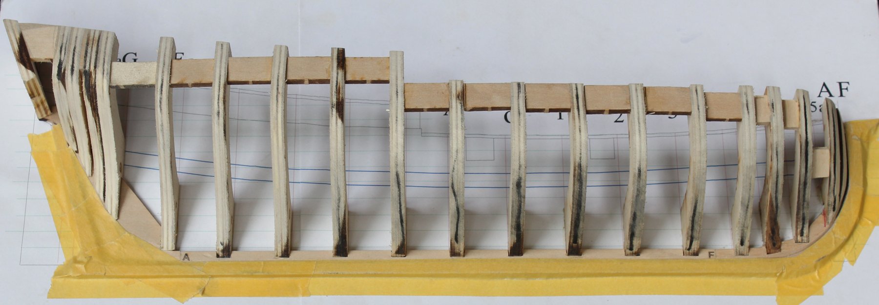
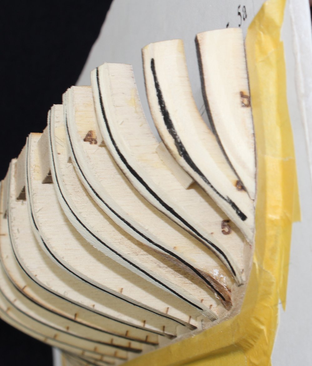
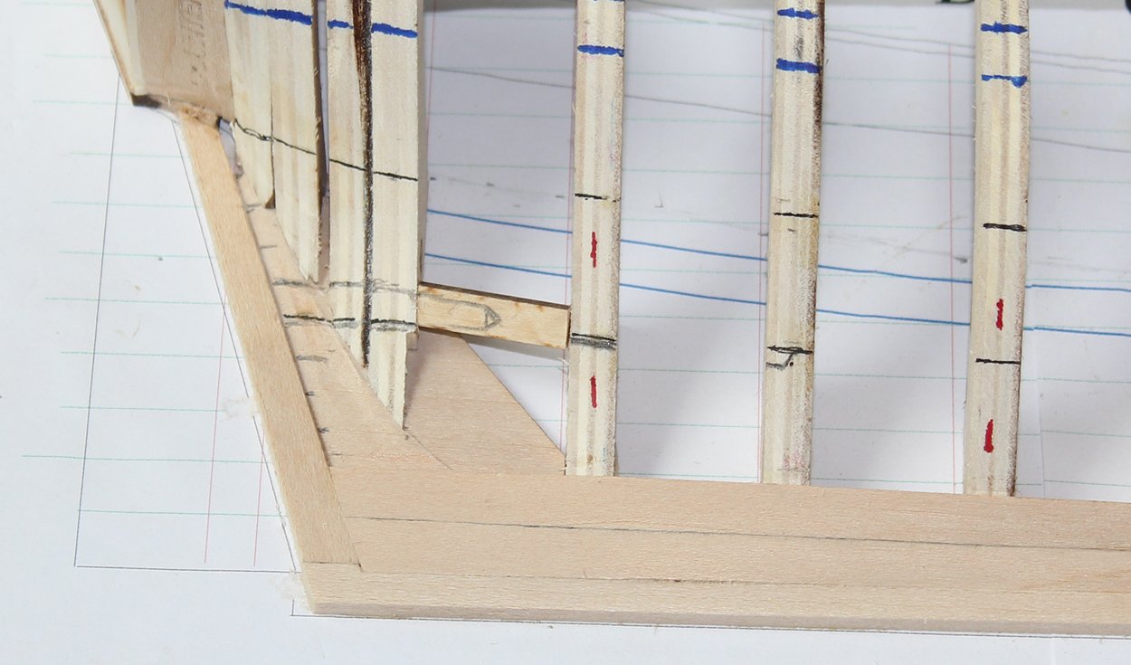
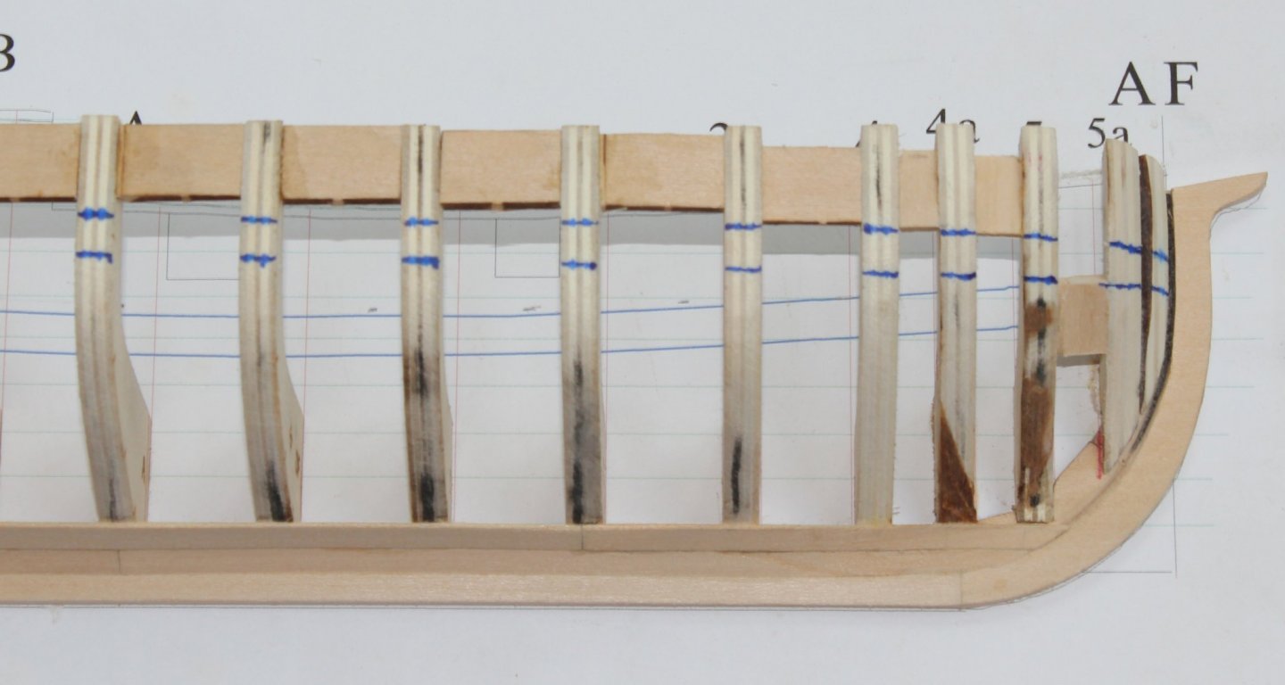
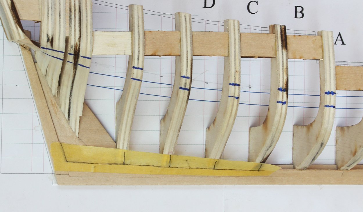
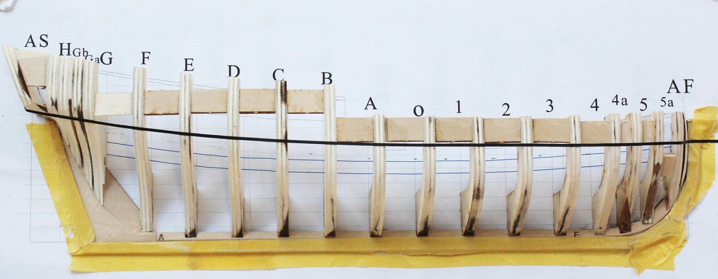
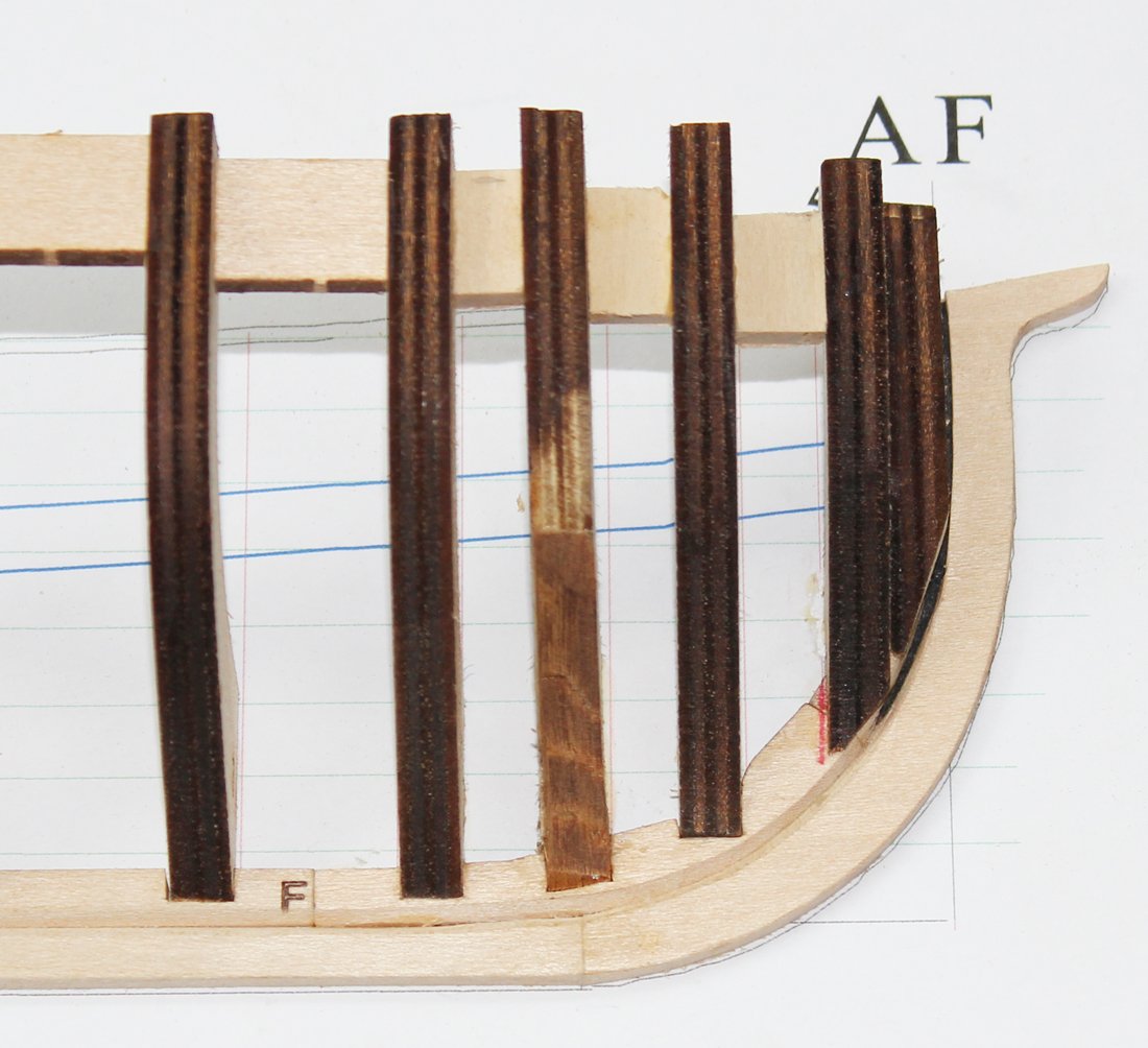
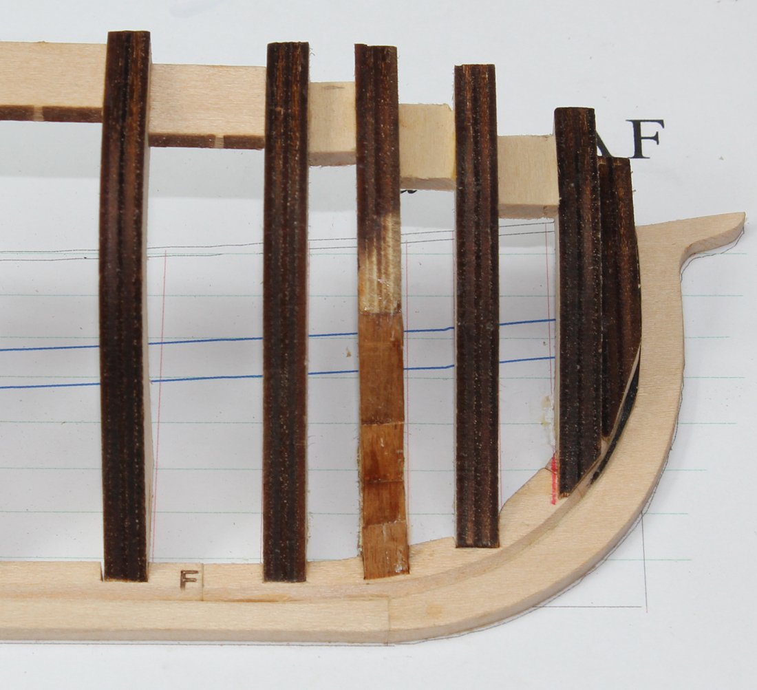
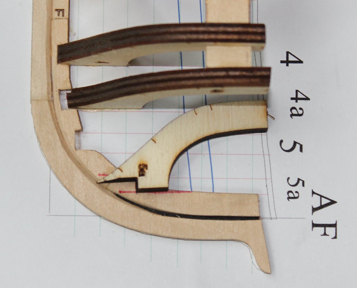
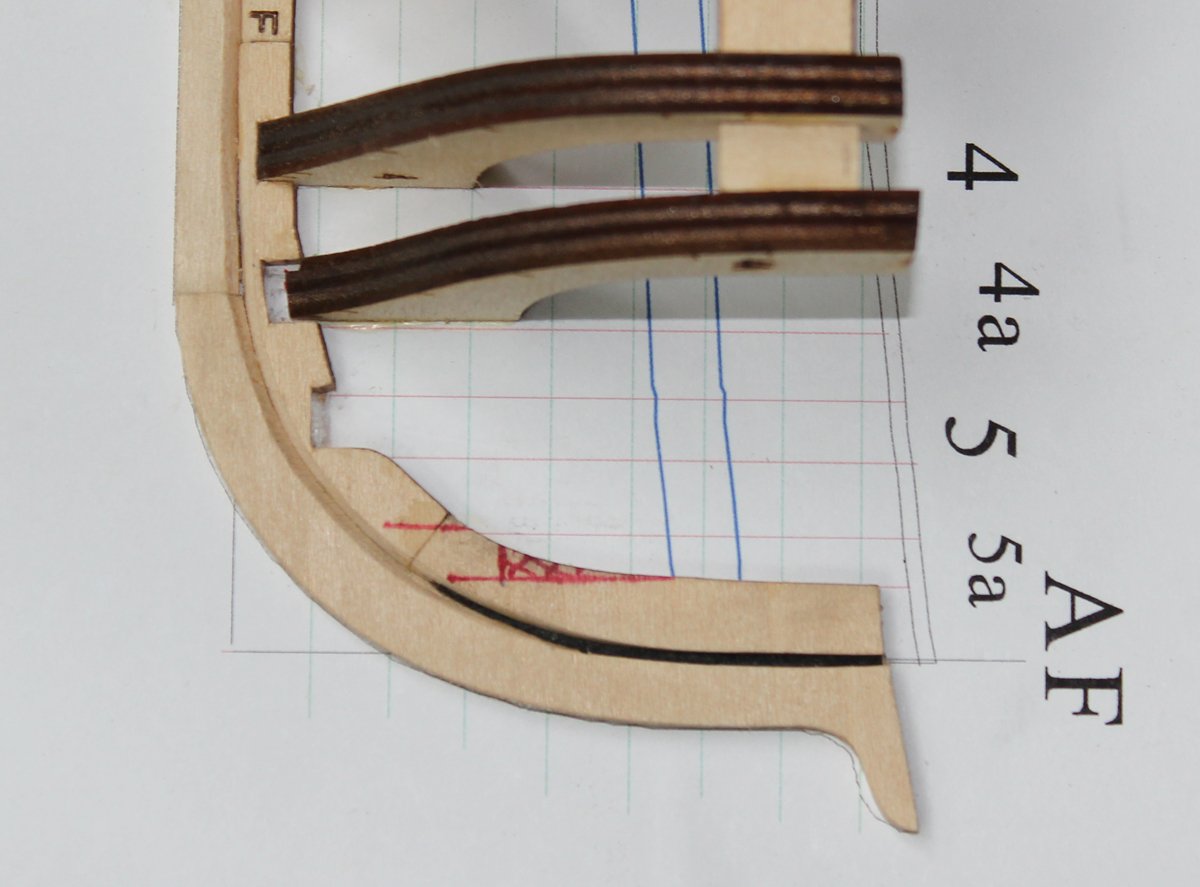
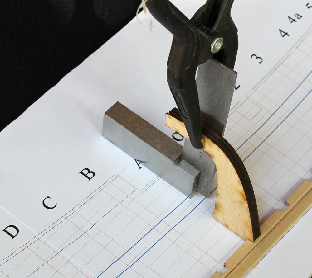
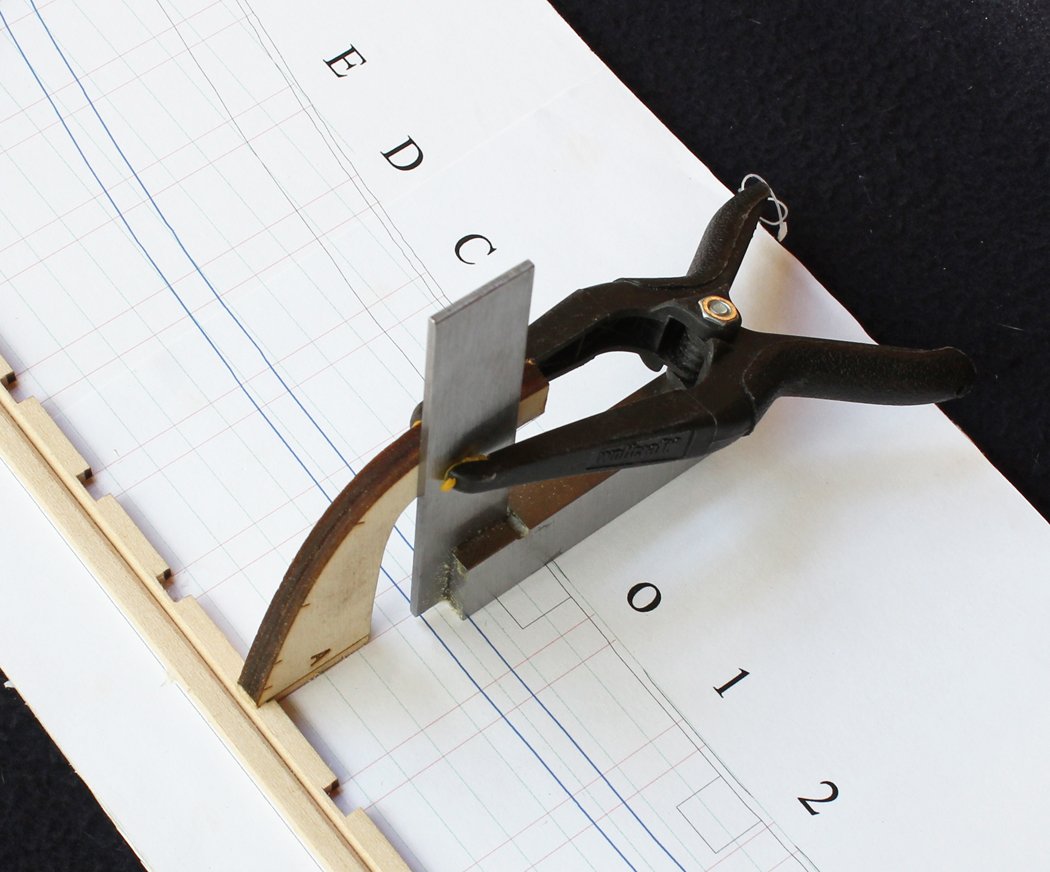
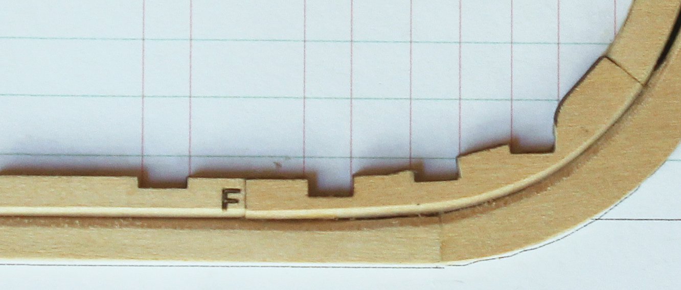
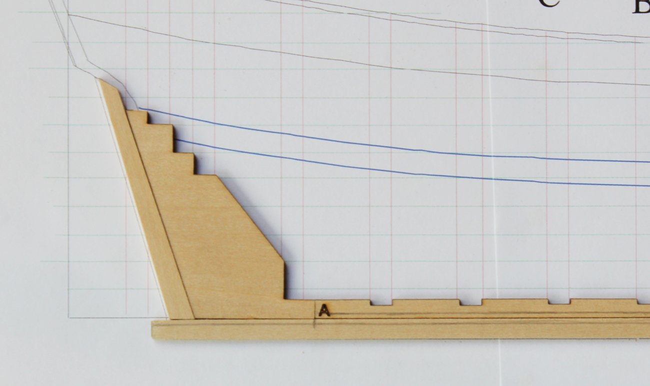
In order to keep the planks from becoming to wide aft, a stealer will be required. This extra plank "steals" some wood from one or two adjacent planks, hence the name. There are two types of stealers: half-checked and quarter-checked. With a half-checked stealer a notch one-half the width of the plank is made in the plank below the stealer; in a quarter-checked stealer a notch is made one-quarter the width of the planks above and below the stealer. I hope the drawings clarify this. A big question is where to put the stealer. As a rule, a stealer would be placed where the arc of the run of planking no longer parallels the wale. The fore end of the stealer extends as far as necessary to maintain a smooth run of planking. Look at the picture below. This nothing more than a piece of thread with a knot tied in it and secured to a random frame. The lower leg is along the border between the lower and middle planking belts. The upper leg is paralleling the arc of the wale. On the deadwood, in pencil, are evenly spaced marks for the ends of the planks of the lower and middle belts (four planks in the lower belt and five in the middle because of the stealer). Play around with the fore end of the string (lengthwise and vertically) to decide where the stealer should be located. Now look at the surrounding plank butts and make sure that the tip of the stealer is at least one row away from a plank butt. You will probably find that the tip of your stealer will land between frames. I glued a spacer between Frames F and G for this reason. The following pictures show a quarter-checked stealer drawn onto the spacer with and without the string. My other models were made with a quarter-checked stealer; this one will be made with a half-checked stealer. No reason other than to do it differently. The quarter-checked stealer is actually more difficult to make and the description of making it can be found in the kit manual.
- 167 replies
-
- 17
-

-
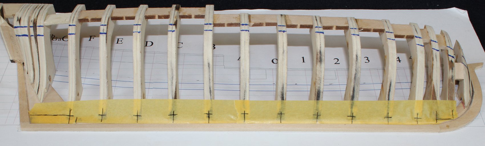
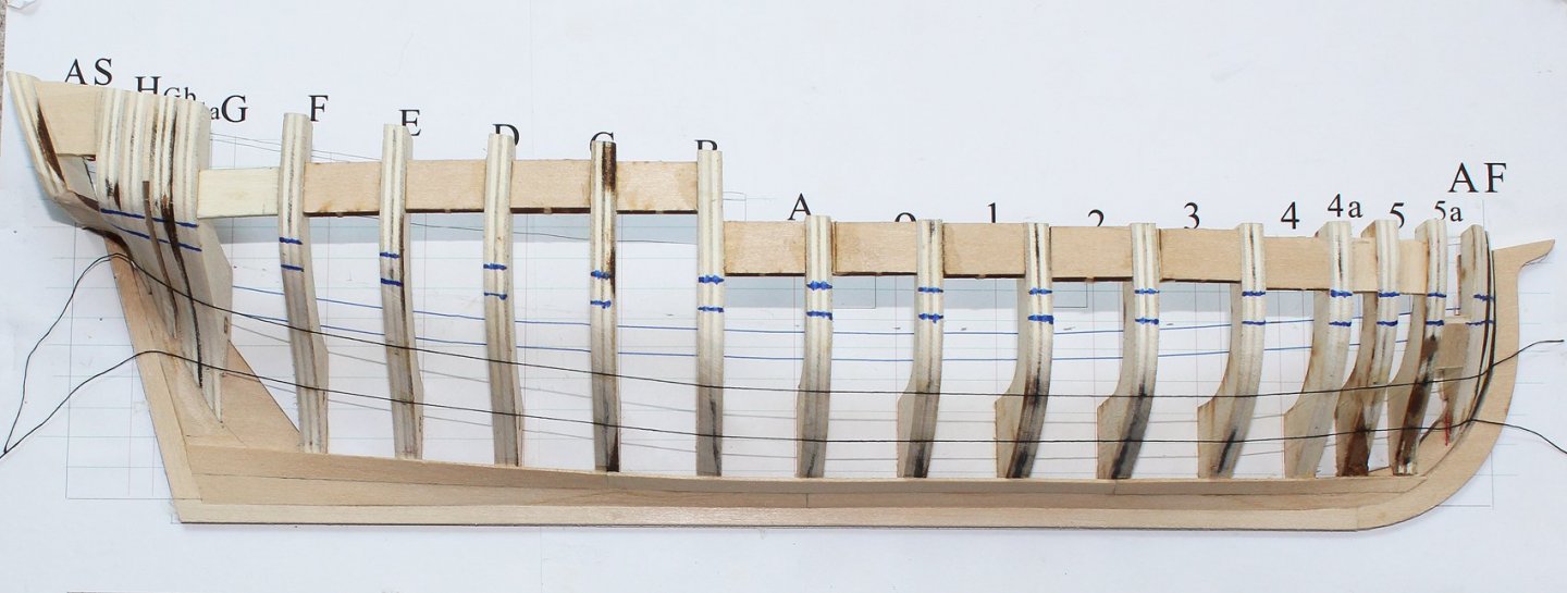
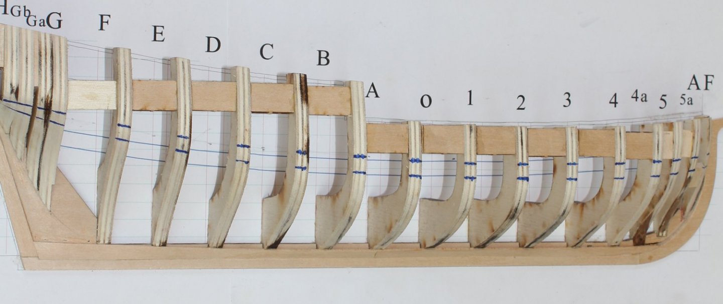
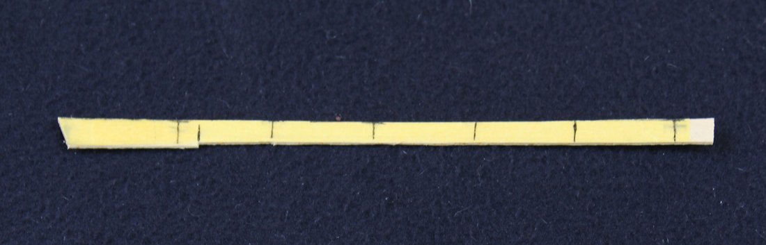
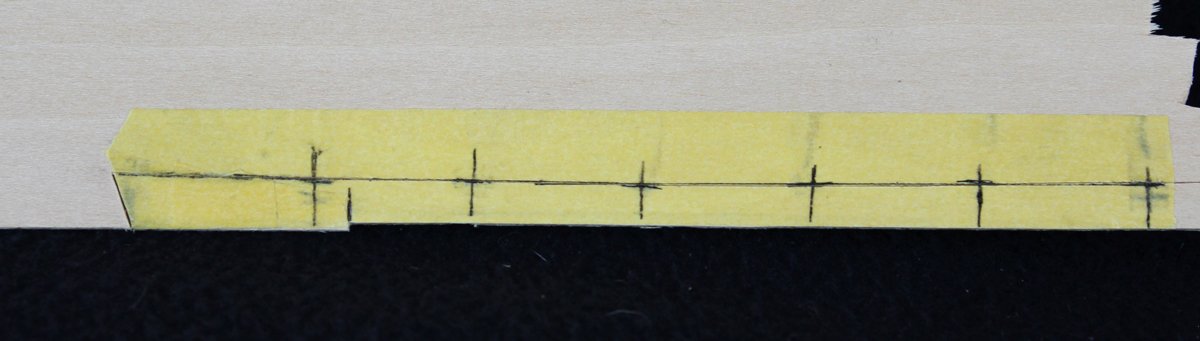
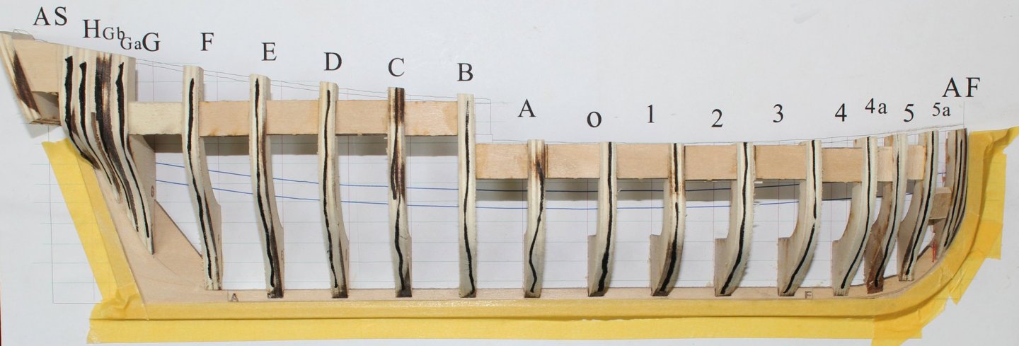
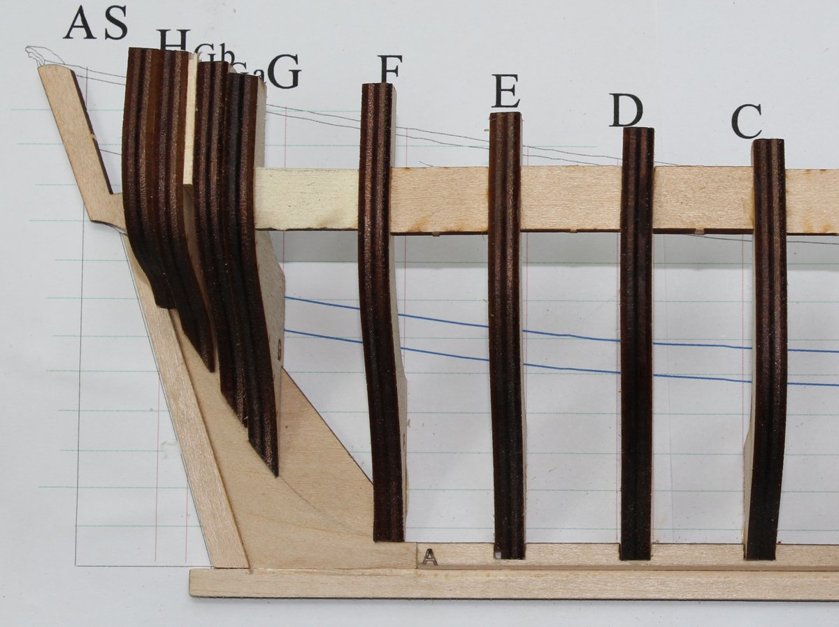
Now that the garboard and broad strakes are completed, it is time to develop the planking belts. I have chosen three belts of four planks each. One could also do two belts of six planks. I simply find the narrower belts easier to work with. The midships area is easy...divide the frame by three. But fore and aft, the relative width of the belts will change. There will be a stealer aft and a dropped plank fore to compensate for this. What is needed now is an aesthetic series of lines for the belts. Play with it until you are happy; again, try and avoid the smiley-face look at the bow. Mark the location of the belts on the frames. On the frames are a series of hash marks on the side of the frames. You can see some of them in the photo above. These represent the locations for the top of the garboard and broad strakes and belt lines on my first build of the kit (this is number 5!). They are a good starting point but I discovered that each build was a little different, depending on the fairing and the actual width of the wider planks. Make a tic strip for each frames. Mark the planking belts and the bottom of the wale on them. Frames C through 2 were identical which is why there are no strips on several of the frames. Remove the tic strips from the frames and divide the lower belt into four equal divisions. Either eyeball it or use a caliper. It is time to figure out the planking scheme. Initially, I spent over an hour to figure this out. Ships were planked in either three-butt shifts or four-butt shifts. This ship will be planked with a four-butt shift. The rules for a four butt shift are as follows: at least three rows of planking between butts on the same frame, a minimum of four feet between butts with one unbroken plank between them and at least five feet between butts on adjacent planks. The distance between frame centers (except at the bow and stern) on this kit is four feet. Take a sheet of paper and line out the frames and twelve rows of planking. Play around with the butt locations. It gets more complicated aft because of the stealer. Eventually, I came up with three possible sequences for the planking. On this ship the butt sequence will be BF3, D1, A4F and C2. As mentioned in the previous post, I realized that the broad strake planking sequence should have been D1 rather than C2. But I did not notice this until the first belt had been completed. And, mea culpa, I decided to leave it alone rather than completely strip the hull except for the garboard strake. Mark the lower belt and the aft part of the middle belt with the butt sequence. I did this in red ink.

- 167 replies
-
- 12
-
-
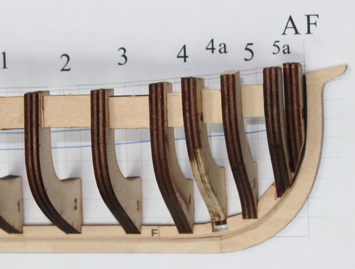
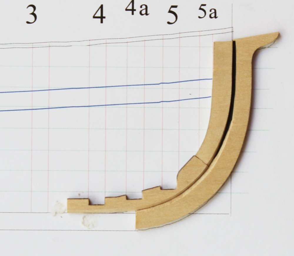
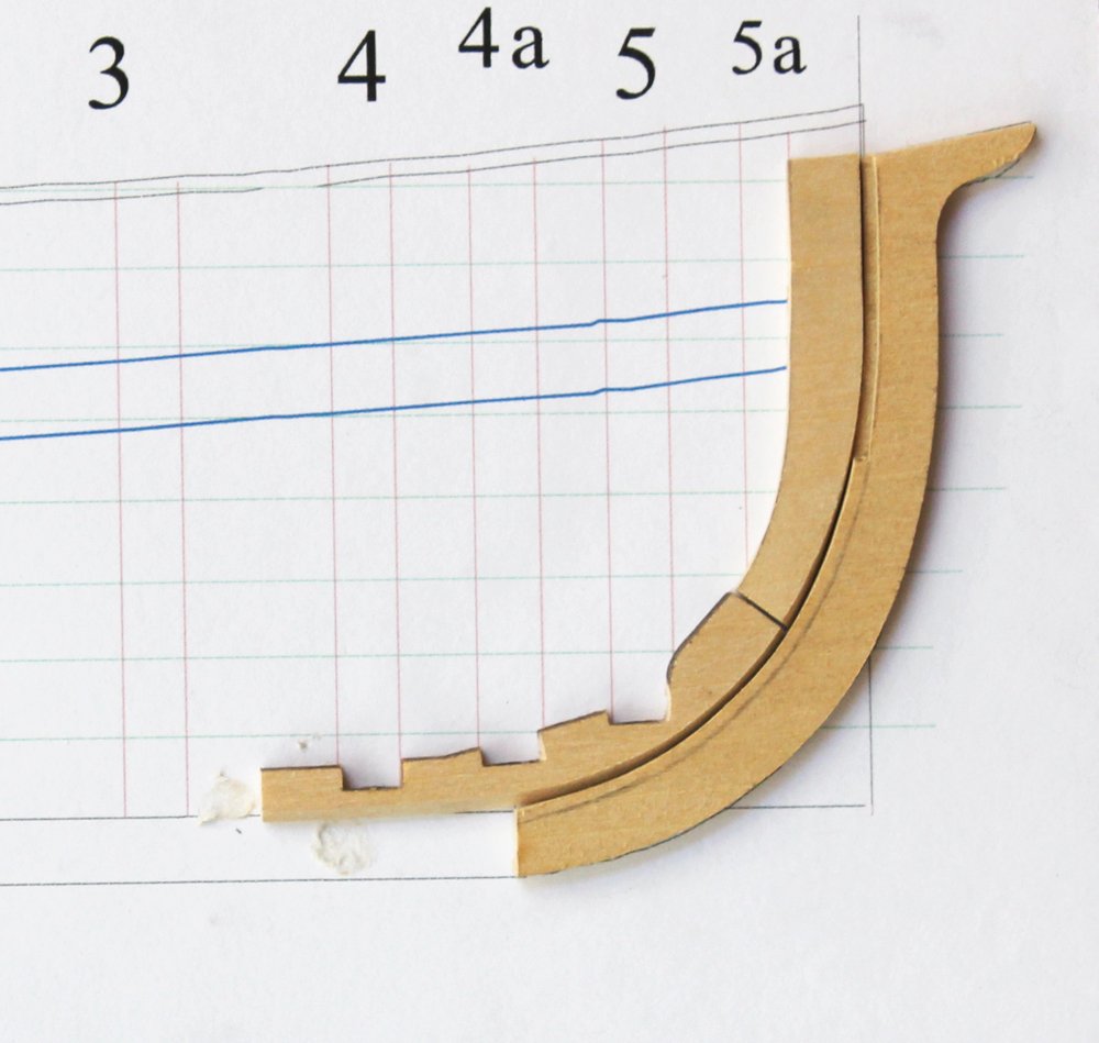
The next row of planking, the broad strake, has essentially the same width as the garboard. However...it is no longer a straight line because the width of the garboard changed fore and aft of midships. Mark the frames and deadwood at the sternpost just as you did with the garboard strake, 12" midships and 14" at the sternpost. Run a piece of string or tape to determine the run of planking. The fore plank will end approximately halfway between Frames 5 and 5a and 0.06" below the first waterline. The plank butts on this model landed on Frames C and 2. In retrospect, Frames D and 1 are a better option, as you will see in the next sequence. Take a piece of tape and place it over the garboard, extending onto the frames. Again, mark the location of the sternpost and frames. Take a soft pencil and rub it along the edge of the garboard strake from the sternpost to Frame C. Mark the height of the broad strake on the tape, put it on the planking sheet and cut it out. When cutting out the planks, leave a little meat on the bone for final fitting to the previous row of planking. Sanding blocks and sticks are the best tool I have found for fine-tuning the fit between planks. Gaps are easily seen by holding the hull up to a light. It will be necessary to sand a bevel into the side of the plank to ensure a tight fit. The angle of this bevel will change based on the curvature of the hull... a relatively flat area like over the deadwood will have minimal bevel and sharply curved areas like the turn of the bilge will have significantly more. Hull planks are caulked for water tightness. This is simulated by rubbing a soft pencil lead along one long and one short edge of the plank. Rubbing all four sides will result in a darker line; if that is the effect you are after, fine. I prefer the more subtle look. Repeat for the other two planks.

- 167 replies
-
- 15
-
-
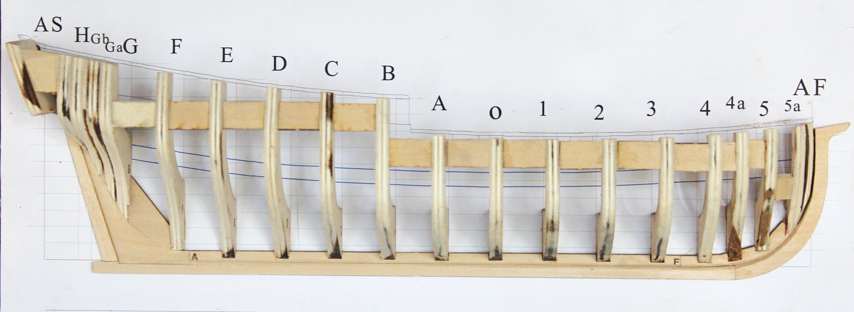
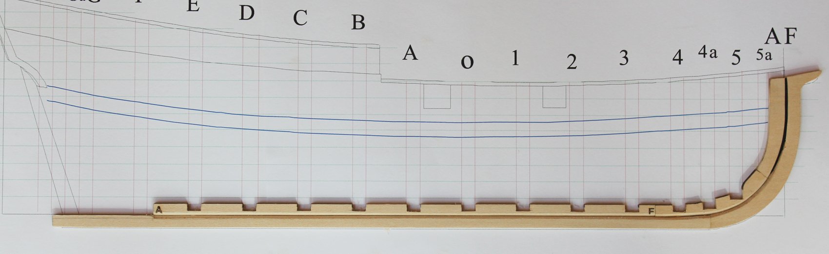
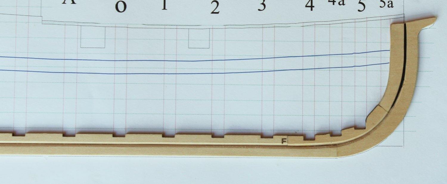
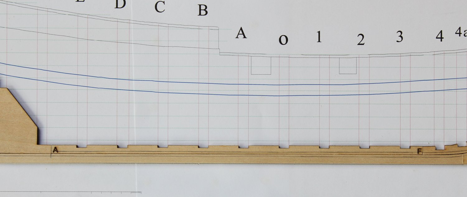
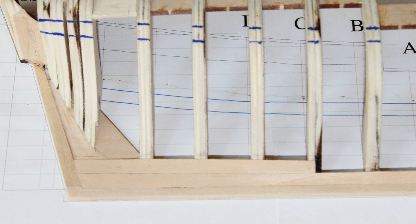
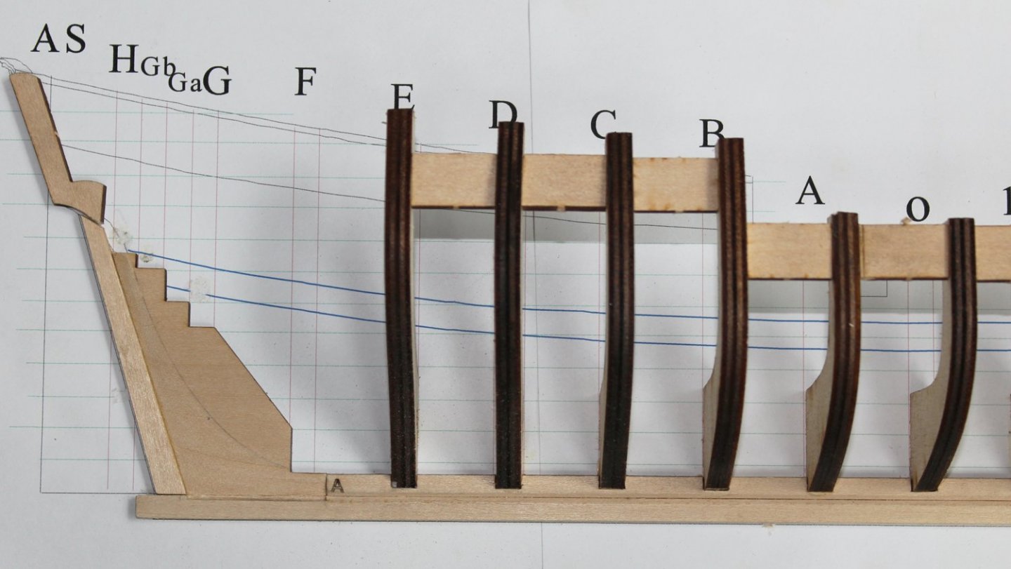
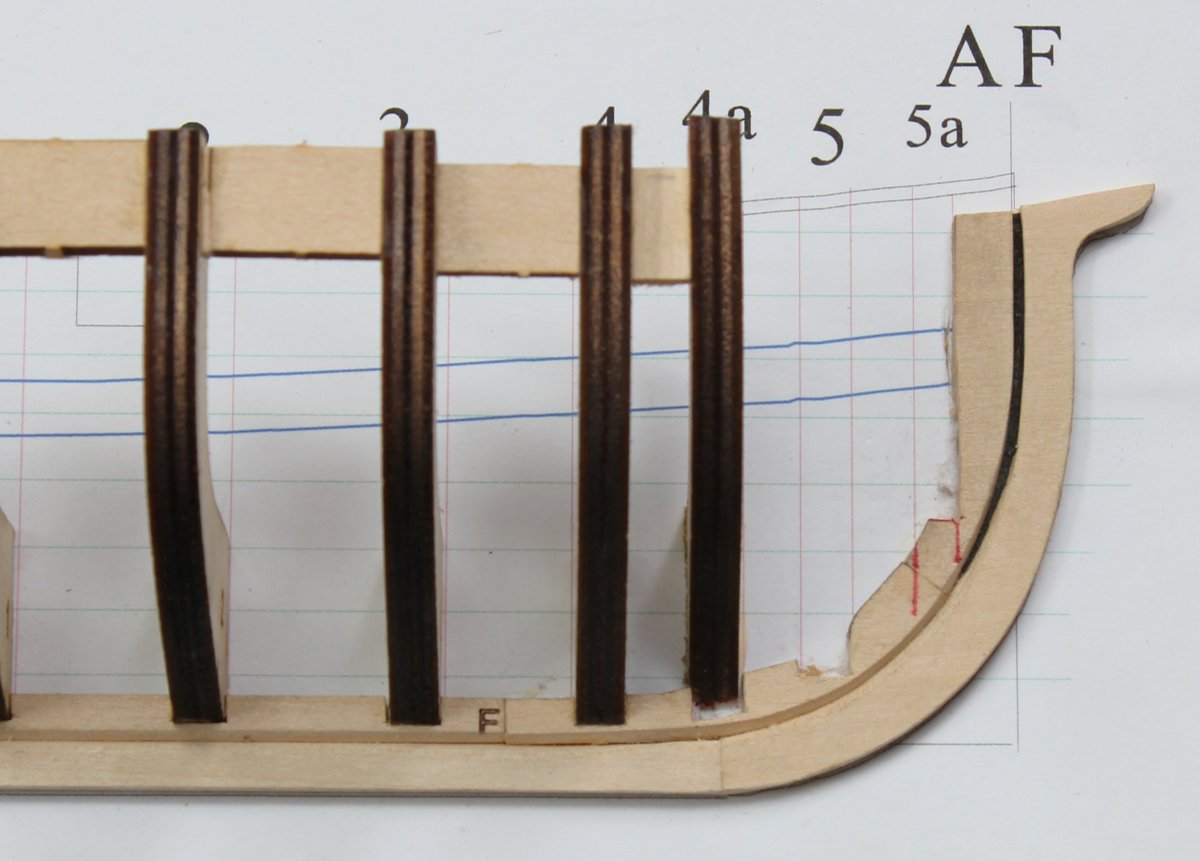
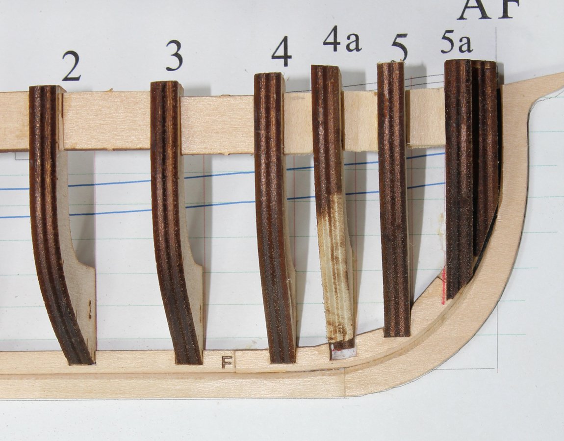
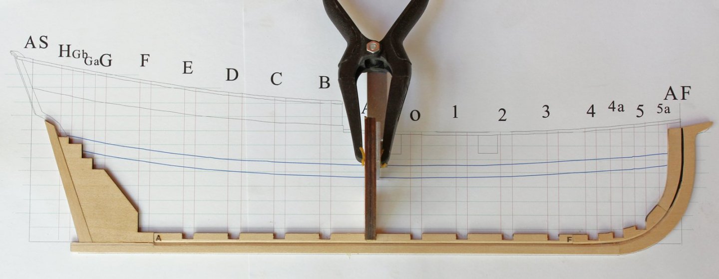
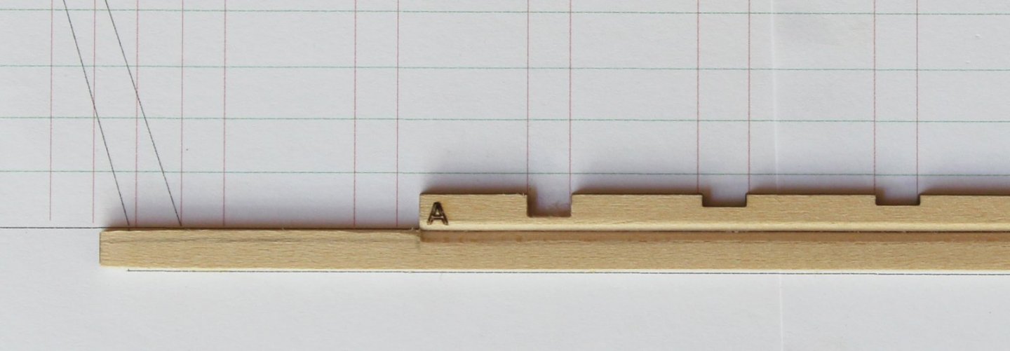
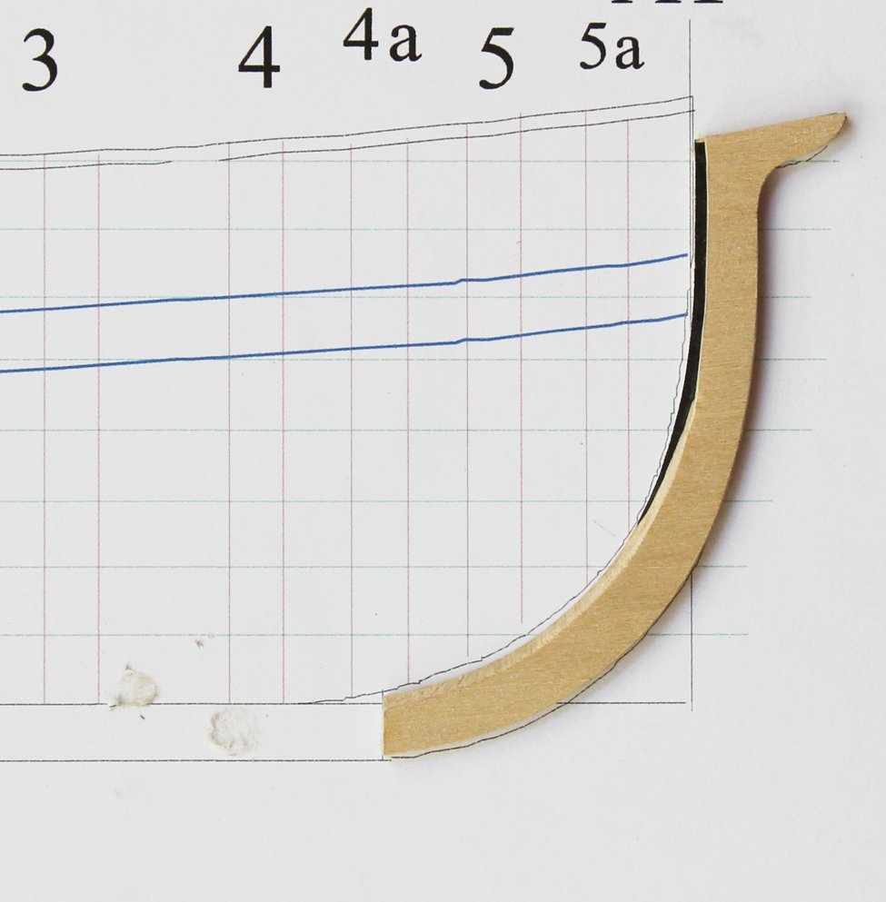
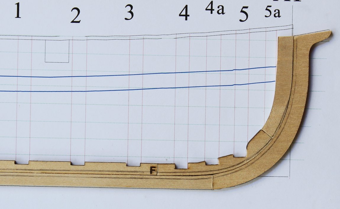
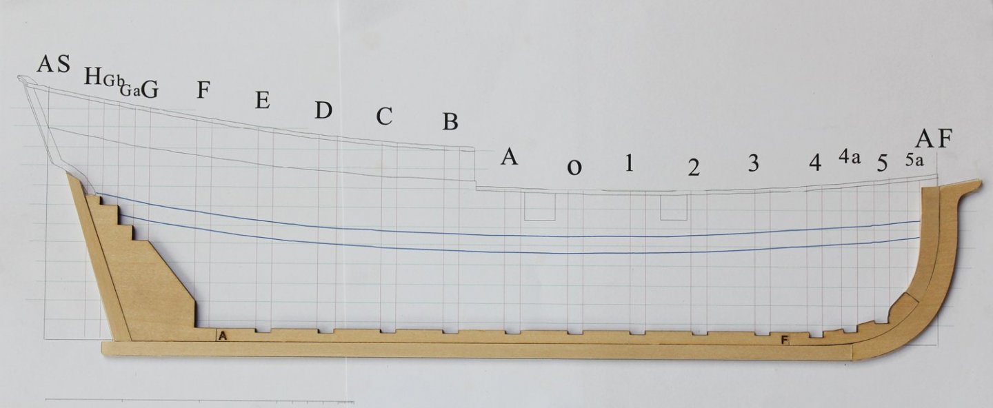
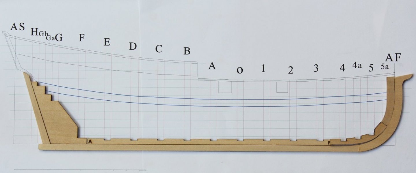
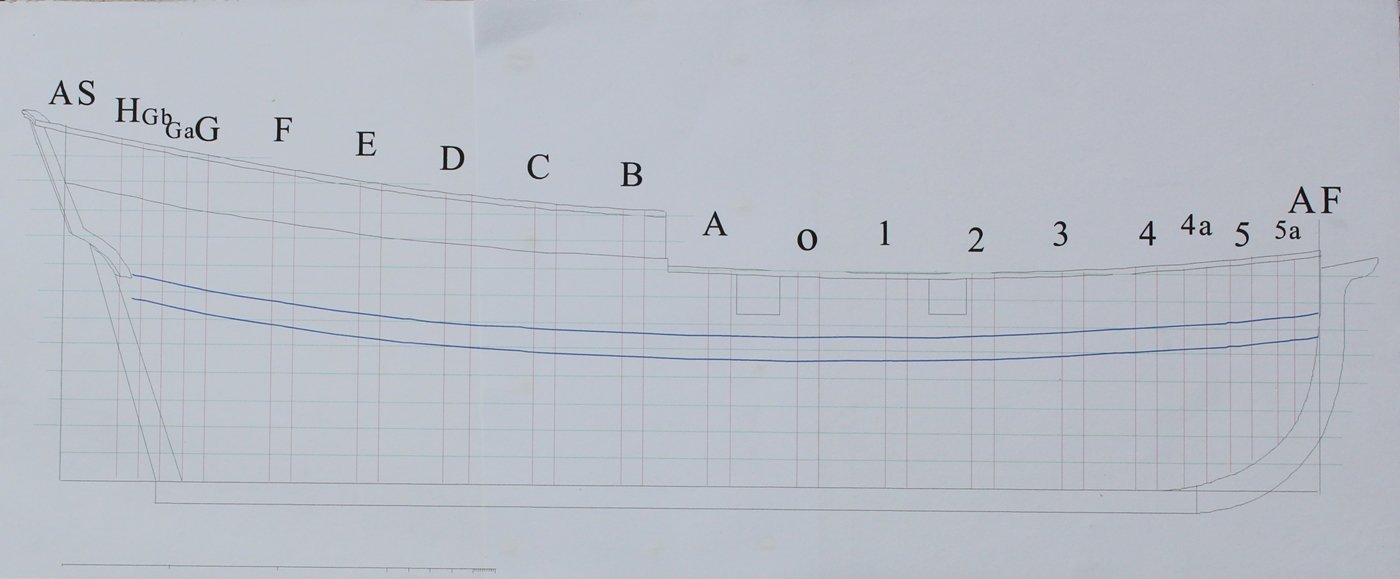
Some builders like to install the wale before the lower hull planking. I prefer to install it after the lower planking belts have been installed. Either approach will give the same results. Before any planking can be installed, the “median plank width” must be determined. This number represents the typical plank width measured at the dead-flat frame. This width varies by size and type of vessel, as well as by where and when it was built. This mid-18th century American schooner would have had a median plank width between 4-12” depending on the availability of materials. I have chosen a median plank width of 9”. The bottom two rows of planks are wider than the other planks and are the garboard and first broad strakes. These planks have a median plank width 1/3 greater than the other planks, in our case 12”. The length of planking was also determined by the availability of lumber. In this era, a length of 20-25’ would be appropriate. At our scale of 1:48, the median plank width will be 0.18"; the garboard and broad strakes will have a median plank width of 0.25". Going forward, all widths cited will be full-size unless otherwise stated. To get to the kit size, divide by 48. Take a strip of paper (tic strip) and mark off the median width of 12". Put the end of the strip into the depth of the rabbet in the midships area (Frames D through 3) and mark this location on the frames. All planks taper as they approach the bow and widen towards the stern. The garboard and broad strakes are no exception. In this little ship, the garboard widens to 14" at the sternpost and narrows to 6" at the bow. Place a mark on the deadwood at the sternpost 14" above the bottom of the rabbet. Remember that the rabbet transitions to a mortise by Frame F. One of the biggest problems builders have is locating the fore end of the garboard too high up the stem. This gives the planking a "smiley-face" look and makes the fore ends of the regular planks too narrow. Take a look at the photo below. The garboard does not extend beyond the fore end of Frame 5 and has minimal rise. On the plan there are green lines spaced 0.33" apart. This is 15" full-size. These are called waterlines and would be numbered from bottom to top; the numbering was not added to keep the plan less cluttered. The fore end of the garboard on this model ends 0.24" below the first water line. Using tape or a thread, connect the midships with the fore and aft locations of the garboard. When happy with the run of planking, mark the frames and remove the tape. There are several ways to determine the shape of planks. During the project I will show two approaches that work for me. Both approaches utilize templates to determine plank shape. I arbitrarily decided that the garboard will be made up from two planks and the broad strake from three. The planks will end on Frame 3. The garboard is the only strake with a straight edge. Place a piece of tape from Frame A to the stern post and another from Frame A to the stem. I always leave extra tape fore and aft so these two pieces will overlap each other at Frame A. Mark the location of the frames onto the tape; then mark the run of the garboard. Using semi-transparent tape makes this process a lot easier. You can see that I have also marked the rabbet/mortise transition in front of Frame F and the run of the plank at the bow and stern. The aft plank template has been placed on the planking material. The kit provides 1/32" basswood sheets. This material was chosen because it is inexpensive, easily cut with a #11 blade or single-edged razor blade, and readily available at craft and hardware stores if you run out. I have exaggerated the notch by Frame F for purposes of the picture. Remember, this is the transition between the rabbet and the mortise. The wood will dive into the rabbet but will lay flat in the mortise. Make a tiny cut at this spot to allow the wood to bend into the mortise. The notch will be sanded to its final width as the plank is given to the hull. This is how it will look when the garboard planks have been installed.

- 167 replies
-
- 13
-
-
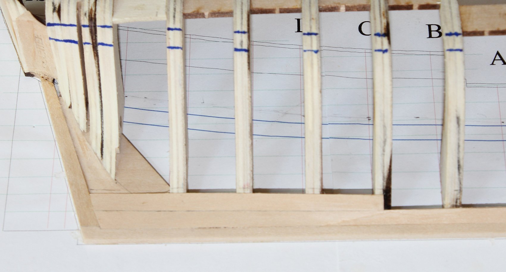
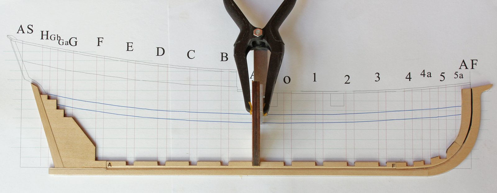
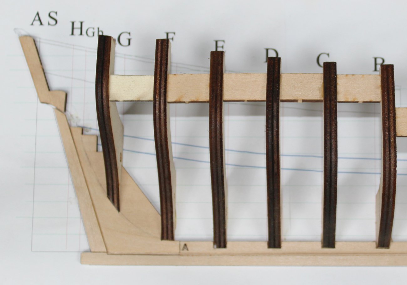
In order to determine the planking belts, we must first find the top and the bottom of the regular hull planking: the bottom of the wale and the top of the broad strake. The wale is a thicker run of planking that adds strength to the hull. It will be located on the plans of whatever ship you are building. It is marked on this plan with two blue lines. Use a square to locate the top of the wale on the frames. Make sure the line looks fair. Then mark the bottom of the wale on the frames, extending the line to the intersection of Frame H and the counter.

- 167 replies
-
- 18
-
-
The NRG is now offering the latest in its series of educational tools for the ship modeler: the Half Hull Planking Project. The purpose of this Project is to teach modelers how to plank a hull using spiling techniques. Even a novice should have no trouble learning this technique with the materials and instructions provided. The tools required for completion of this kit are inexpensive; even a Dremel is optional. The price for the kit is $52 for NRG members and $65 for MSW members. The kit will include everything required to build the kit except the building board. The manual will be available as a download. If you are interested , please contact the NRG office at info@thenauticalresearchguild.org. You can follow the construction here:
-
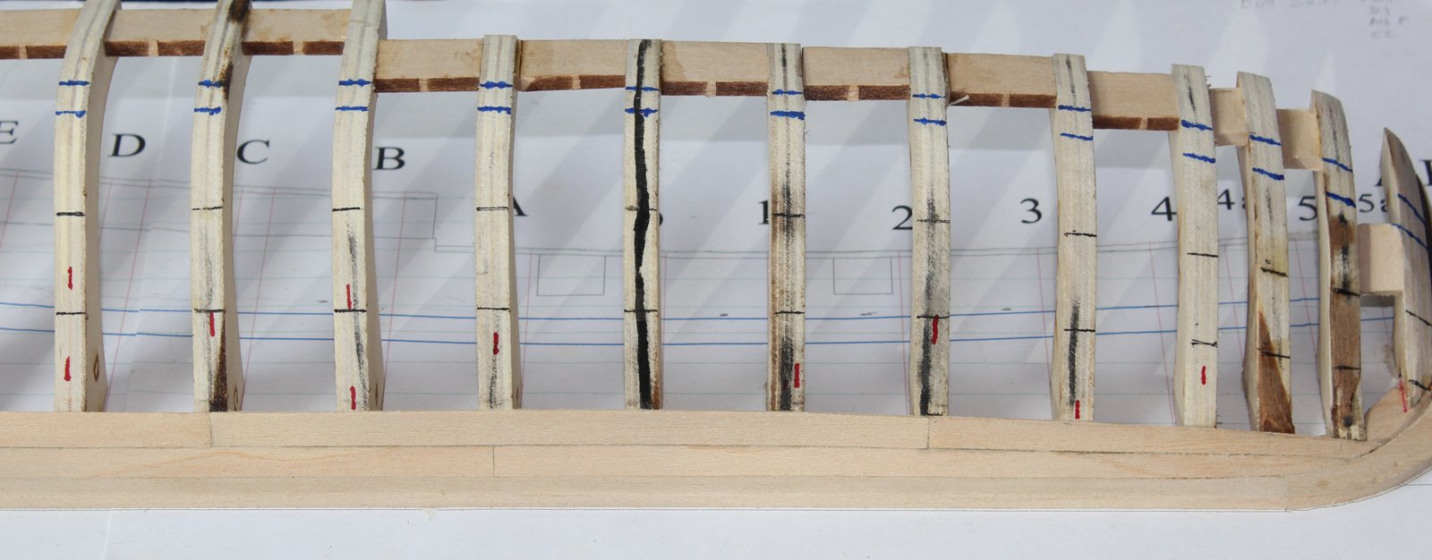
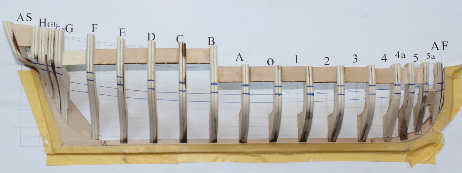
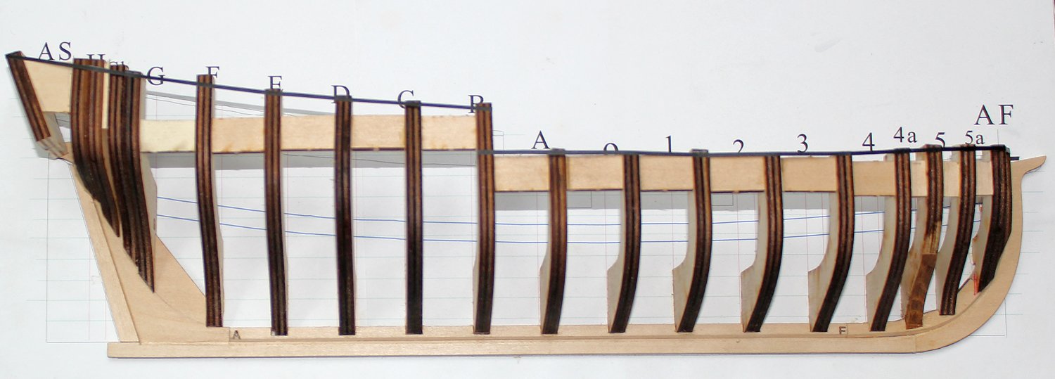
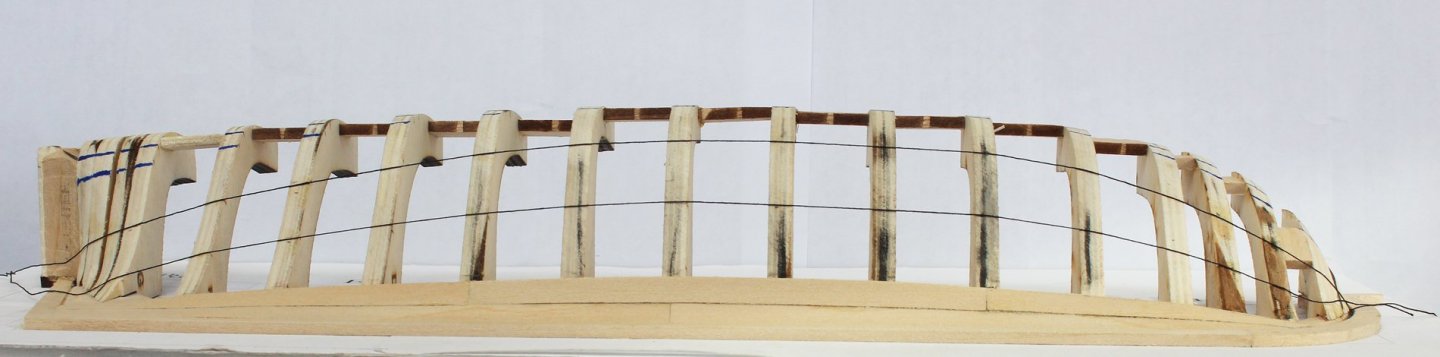
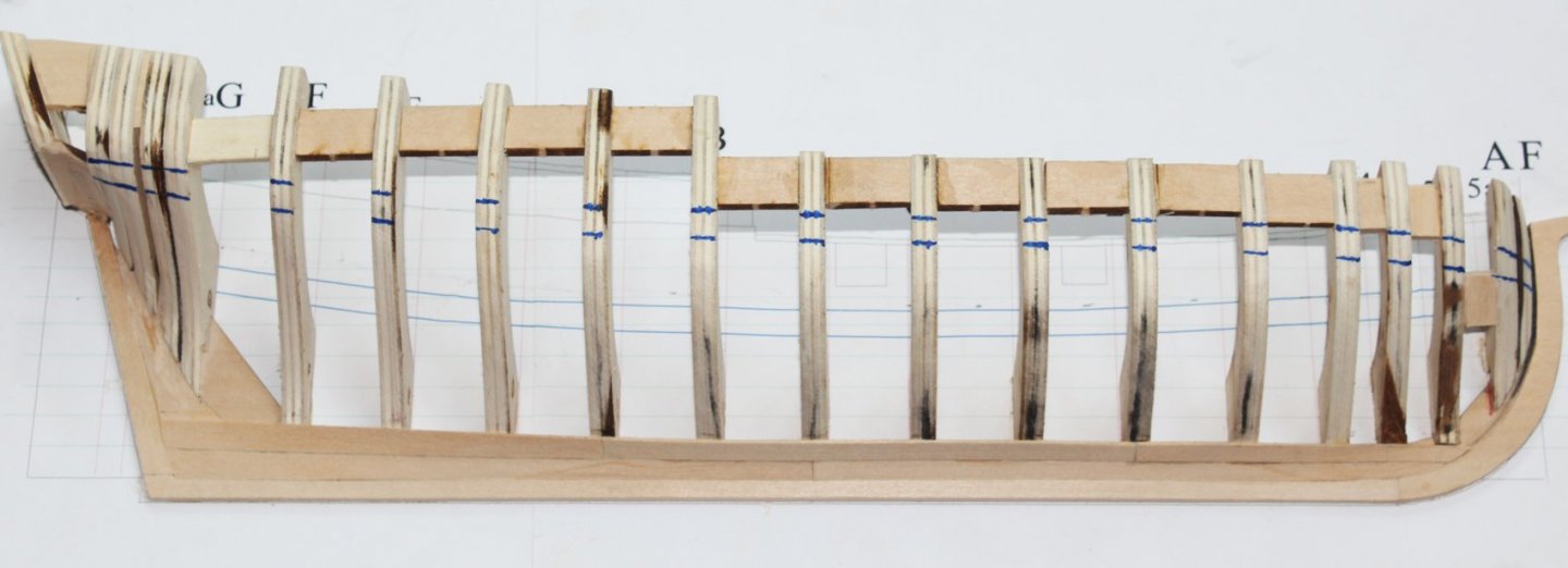
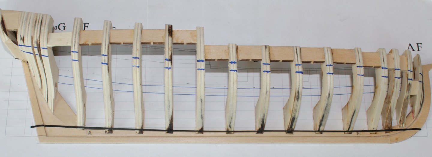
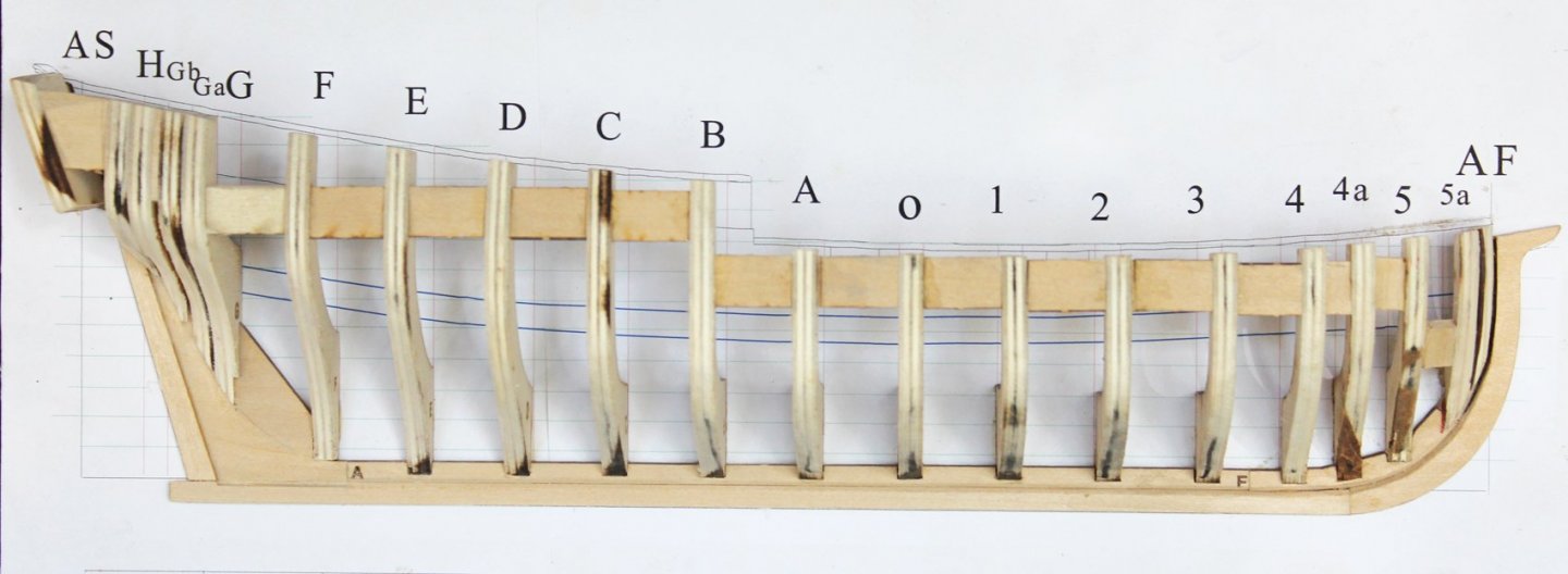
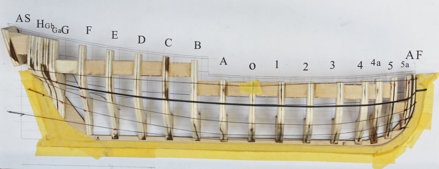
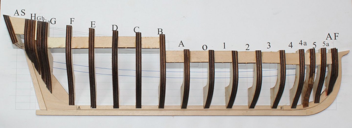
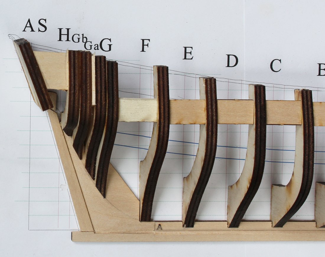
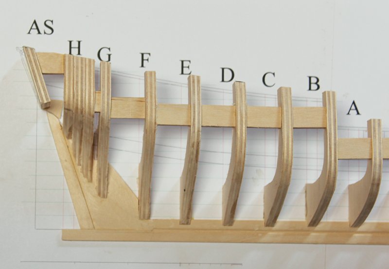
Work has continued on fairing the hull. The picture show how I determine if the hull is fair. The thicker black line is chart tape. The thinner lines are thread. Bulges and depressions are easily seen this way. The red marks on the frame is where more work is needed. After I am happy with the shape, I take thin battens and lay them across the frames, moving them in different diagonal directions to triple check my work. If you take off too much, simply glue a shim onto the frame, as I did with Frame 5. The fairing is complete except for Frame H. You can see that most of the black lines have been sanded away.
- 167 replies
-
- 25
-
-
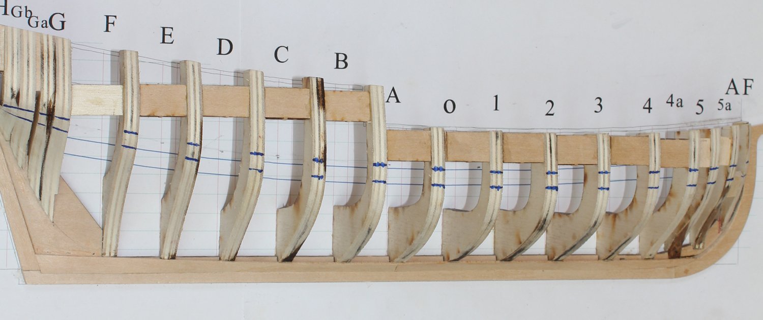
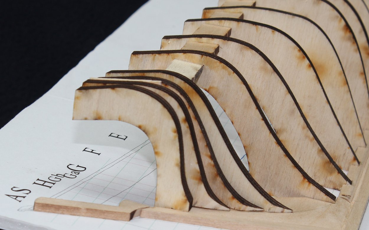
You can see that a lot of the black lines have been sanded away. Time to put it aside for the day.

- 167 replies
-
- 23
-
-
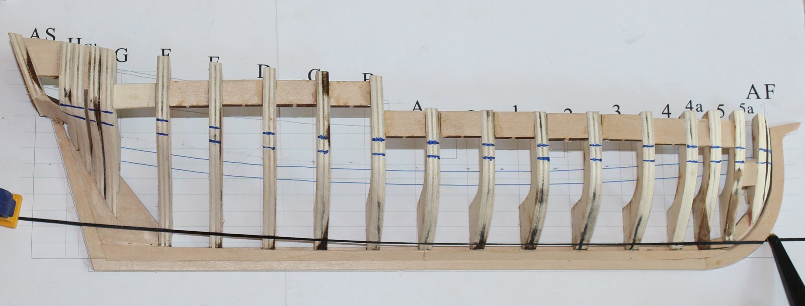
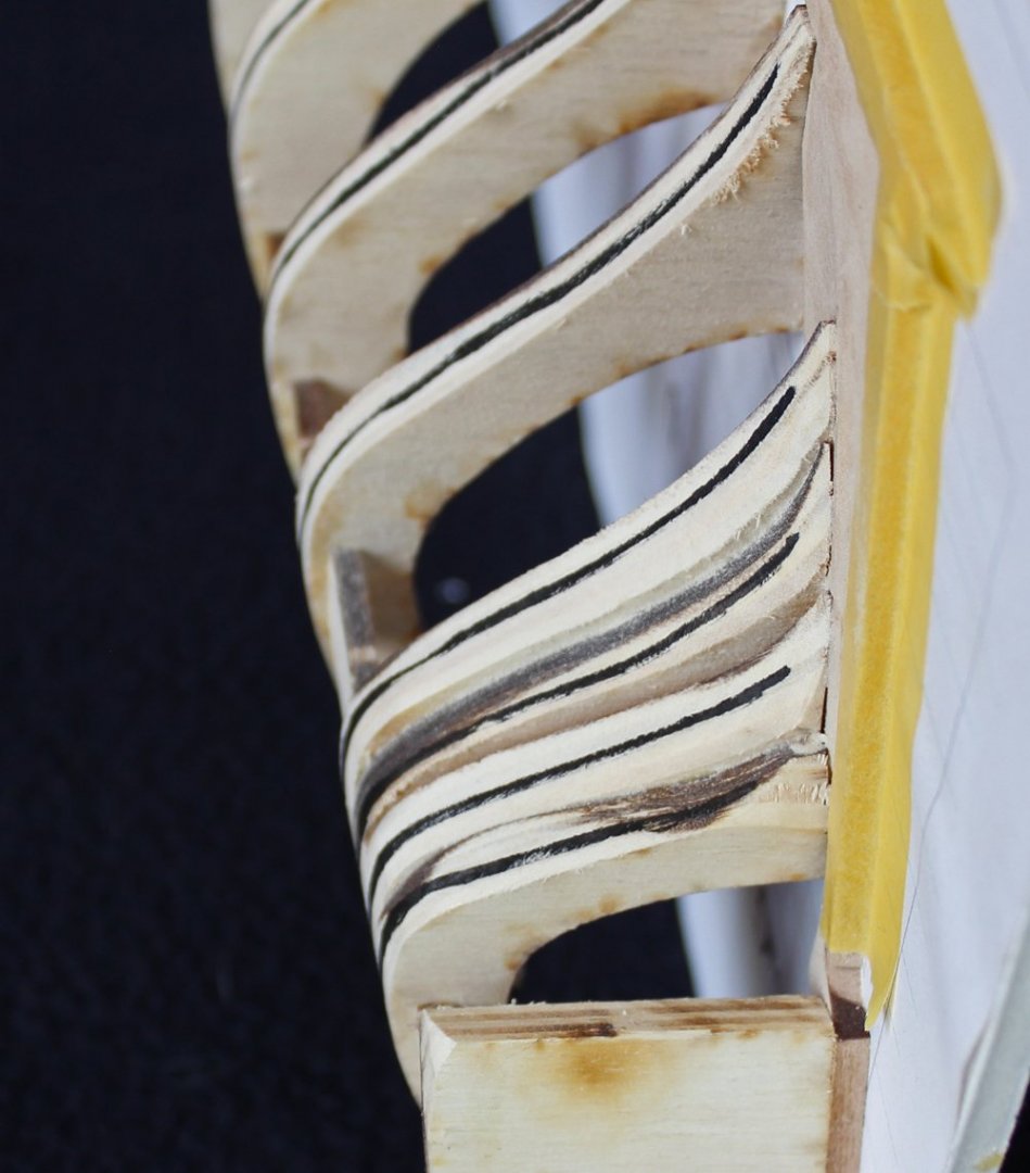
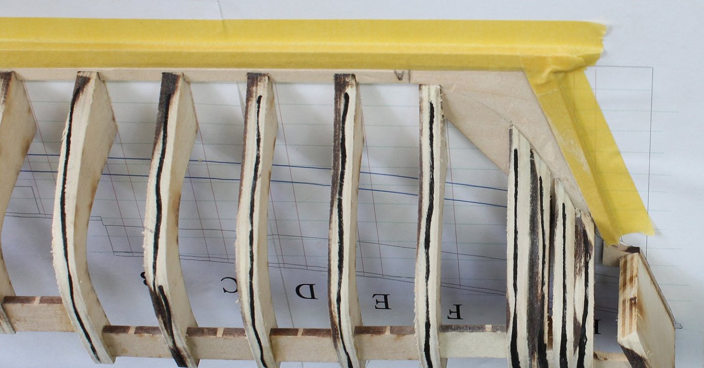
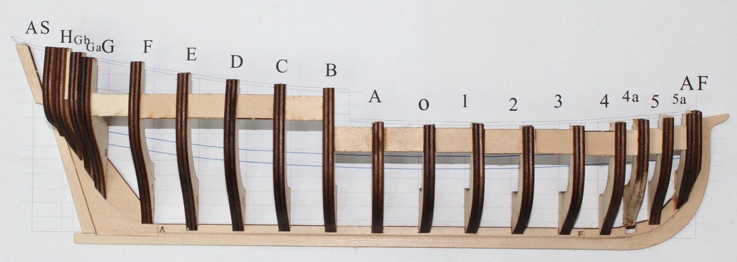
Hull fairing has started. I everyone has their own preferences regarding tools for the job. I use a combination of flat and round sanding blocks and sanding discs on a Dremel. Because the backbone is soft basswood, I have protected it with masking tape. After the rough fairing has been done, I draw a line down the frames. Once these have all been sanded off, the hull is closer to fair. The next step will be to run battens of black thread, chart tape or wood to make sure there are no irregularities.

- 167 replies
-
- 18
-
-
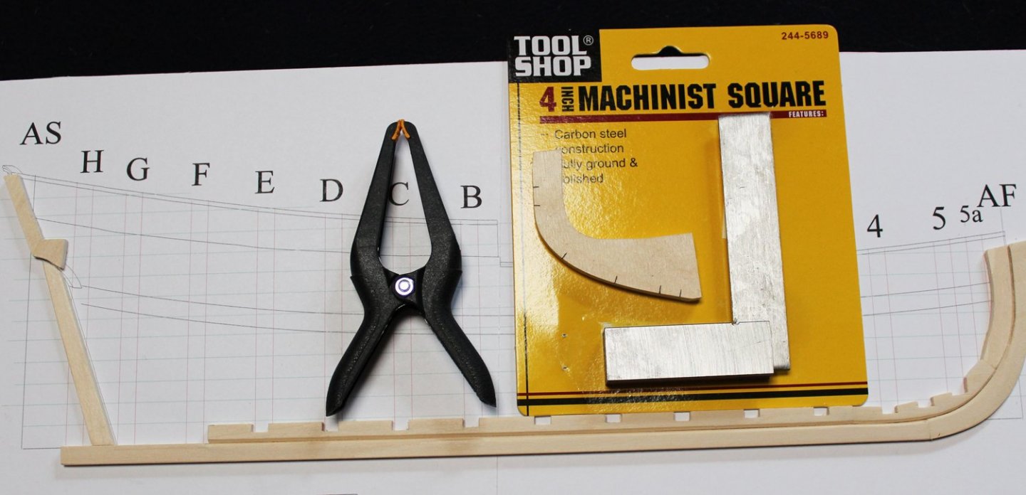
Frame 4a was repaired with 4 pieces of 1mm walnut stripwood left over from a kit. These measured 1 3/8", 1", 1/2" and 3/8". Each one was glued to the frame starting at the depth of the rabbet. Once dry it was sanded smooth. The first picture shows the four individual pieces and the second one shows the frame after the repair has been sanded smooth. The stern frames need to be installed next. Because of the tight curves in the hull, I have made this area semi-solid to facilitate planking. Taper the feet of Frames Ga, Gb and H and install them onto the deadwood. A filler block will make the whole assembly very strong and stable. This filler can be placed either between Frames G and Ga or between Frames Ga and Gb, depending on how you mount the frames. I have done it both ways. Glue the transom piece onto the "L" and make a filler from a scrap piece of basswood. Using the machinist square, mark the fore and aft faces of the frames with the location of the bottom of the rail. Transfer these marks to the edge of the frame. I use a piece of chart tape to finesse the line of the rail. Once happy with the flow of the line, I mark the frames and sand them down to that line. The carcass is now complete. To get to this point should take approximately 10-15 hours of uninterrupted work. The next step will be to fair the hull.

- 167 replies
-
- 19
-
-
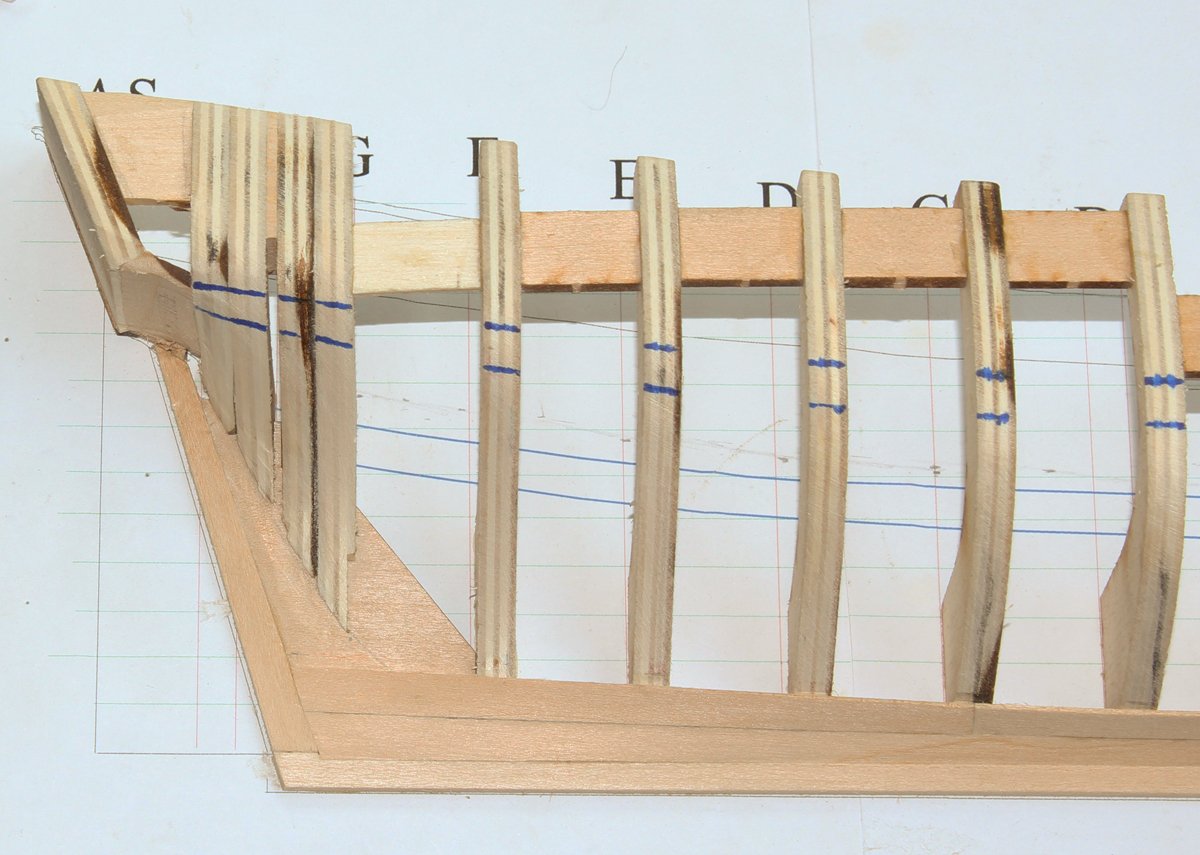
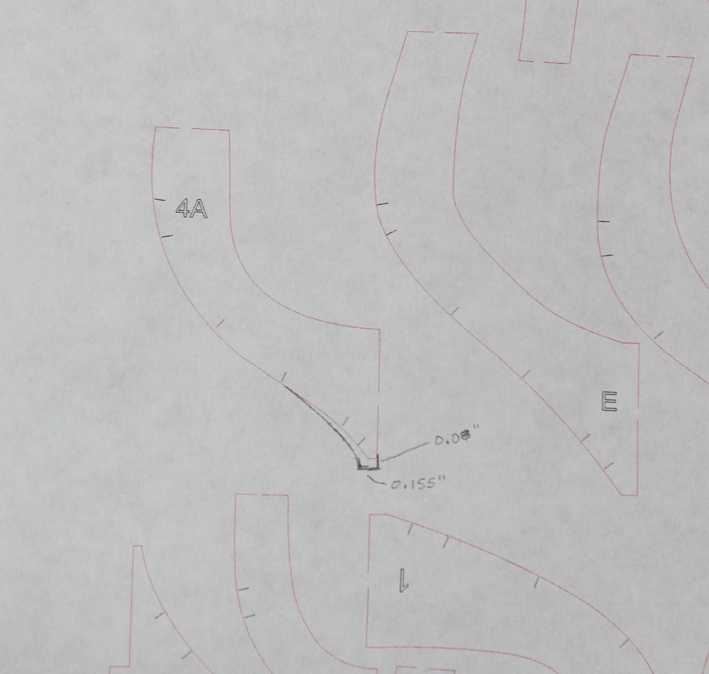
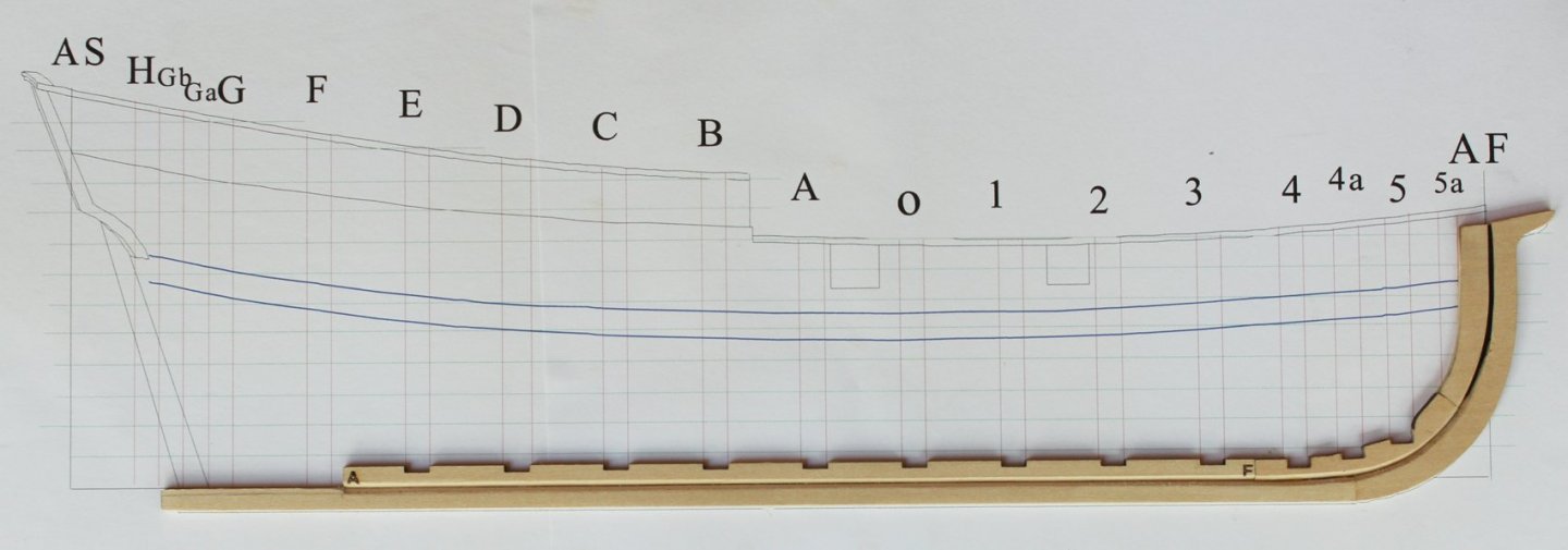
The bearding line on the deadwood is made by temporarily installing Frames F, G and H and marking the fore foot of the frame on the deadwood. The frames are then removed and the points are connected with a French curve or freehand. Aft of the bearding line, the thickness of the deadwood decreases until it is the same depth as the rabbet. In the picture you can see how the deadwood blends into the mortise/rabbet on the aft end of the keel. This was done with a sanding block. The deadwood, stem and L-shaped piece were glued in place. The "L" will be the foundation for the transom and counter. There is no attempt to fit it carefully to the top of the stem as this will be covered with planking. Install Frames F and G and their fillers, cutting the angled foot of Frame G before gluing to the deadwood. Now let's turn our attention to the bow. At this point I determined that Frame 4 was designed incorrectly. You can see the problem on the sketch as well as the correction needed. For right now, Frame 4 was installed 0.08" away from the depth of the notch. This will be corrected after the rest of the bow frames have been erected. For the same reason that the keelson notches were cut shallow, the slot for Frame 5a was not cut at all. Extend the lines for the fore and aft faces of Frame 5a onto the stemson. Then locate where the aft foot of the frame approaches the rabbet, as seen in the first picture. Draw a horizontal line on the stemson to represent the depth of the notch. These lines are in red. The hatched area in the second photo will need to be removed. The final result is seen in the third photo. Taper the foot of Frame 5 and install it and its spacer. Frame 5b sits directly on the stemson. Its purpose is to provide a solid gluing surface for the end of the planks so position this just behind the rabbet. In the pictures one can see that Frame 4a has been sanded in preparation for repairing the frame. Remember, glue does not adhere well to laser char.
- 167 replies
-
- 15
-
-
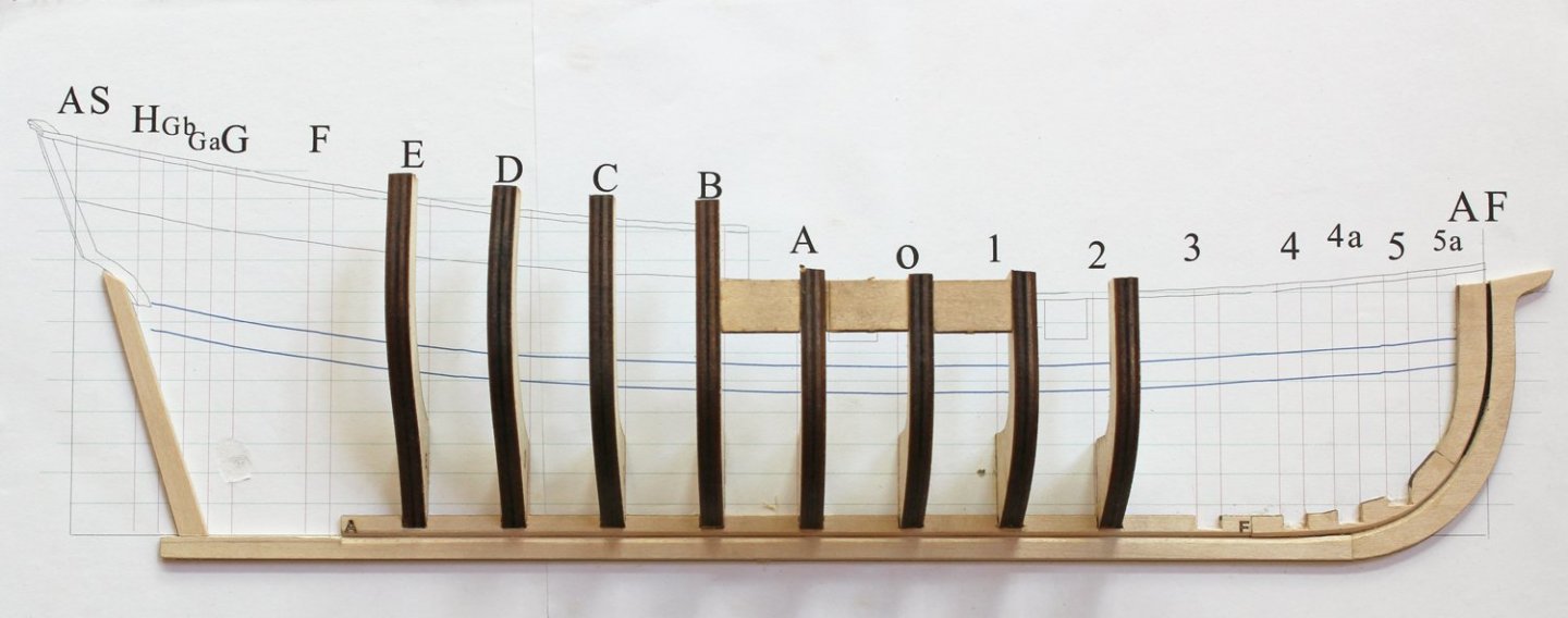
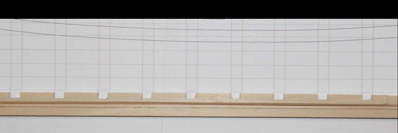
In order to prevent breakage of the keelson and fore keelson, the notches for the frames were cut too shallow. Deepen the notch so that the horizontal component is just above the top ob the rabbet. The picture shows how much it needs to be deepened. This was easily done with a razor blade. These frames are a little different than seen in a typical POB kit. The reason for this was to make clamping the planks against the frames easier. But the downside is the possibility of sloppy vertical alignment. Using an inexpensive machinist square and spring clamp, the frame is held plumb and square to the keelson. The red frame lines on the plan help get the correct alignment. The frames on either side of the dead flat were installed first. Each frame only take a few minutes to install. After Frames 2-E had been installed, spacers were placed between the frames to provide strength to the assembly. The spacers are provided in the kit but will need to be sanded or shimmed up for a perfect fit.

- 167 replies
-
- 21
-
-
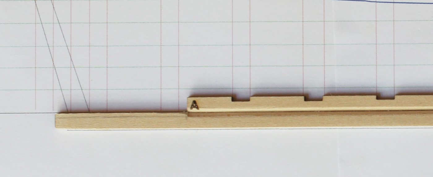
Now that the rabbet has been drawn onto the various pieces, it is finally time to make some sawdust. The keelson rabbet is easy since it is a straight line on both pieces. There are many tools you can use to make the rabbet: sanding block, free-hand sand paper, straight-edged razor used as a scraper, chisel or plane. Chisels and planes are quicker but most novice ship builders do not have access to these tools. This rabbet was made with a sanding block and 120 grit paper. The keel rabbet is almost as easy. At the bow end there is a gentle upward curve which is easily sanded in. I wrapped the sandpaper around my finger to get the curve. Recall the line drawn on the keel at the deadwood? This marks the limit of the 45 degree rabbet and the beginning of a mortise, which will be cut in later. The bow rabbet is more complicated. Starting with the fore keelson, the angle of the rabbet steepens as the width of the rabbet diminishes (refer to the picture in the previous post). The depth of the rabbet is a constant. I used a sanding block to create this part of the rabbet. This narrowing of the rabbet continues onto the stemson, with the rabbet disappearing completely between the fourth and fifth waterlines (the horizontal green lines). Now let us draw attention to the stem. As the width of the rabbet on the fore keelson and stemson diminishes, the width on the stem increases. At the point that the rabbet is entirely on the stem, the rabbet becomes a mortise. You can see how the rabbet transitions in the next picture. In the second picture I have darkened the mortise portion of the rabbet to help illustrate the point. You would not do this on your hull. Finally, I have fit the three components of the stem together to show the completed rabbet at the bow. And the final result. Glue the pieces to the building board and clean up the transition between the keel and stem.

- 167 replies
-
- 19
-
-
Planking the hull
tlevine replied to shortgrass's topic in Building, Framing, Planking and plating a ships hull and deck
And I rarely use anything but yellow glue. What I will occasionally do is put a tiny bit of CA on a plank that is impossible to clamp but I will also have yellow glue adjacent to the CA for my "real" holding power. Everyone has their own preferences. -
The rabbet is nothing more than a groove cut into the wood to secure the edge of the planking. This groove is always 90 degrees because, after all, the plank ends and edges are 90 degrees. Along the keel, that results in a 45 degree cut on both the keel and keelson. As the stem rises, the rabbet rotates so that on this hull with its bluff bow there is a 90 degree cut (mortise) on the stem and not cut on the stemson. Obviously, this is a simplification and if you are interested, read one of the several bibles of model ship building. The depth of the rabbet will be equal to the thickness of the planking, in this case 1/32". Along the keel and keelson, the width of the rabbet will be twice this thickness (1/16") or 1/32" on both sides. This is much easier to demonstrate than describe. Take a compass and draw in the rabbet on the upper and outer surfaces of the keel and the lower and outer surfaces of the keelson. Do not draw anything onto the deadwood. As the stem rises, the width of the rabbet narrows until it is 1/32", the thickness of the planking. This is accomplished by narrowing the rabbet marking on the stemson side while maintaining a constant width on the stem side. Hopefully the pictures make more sense than my description.

- 167 replies
-
- 26
-
-
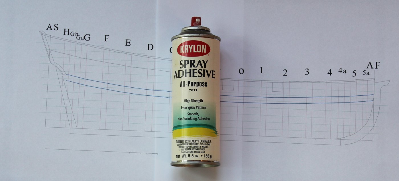
How often do we hear from our fellow modelers that they envy the power tools and gorgeous workshops that some of us are lucky enough to own. I admit to having some nice tools but most of my building is down on my kitchen counter. So one of the requisites for this project was that it would be built only using tools that even an entry level model builder would own. This includes things like sandpaper (various grits), Xacto knife with #11 blade, clamps, tape and glue. It is not even necessary to use a Dremel, although it will shave a lot of time off the construction process. Another very useful although optional item is a self-healing mat. The planking material will be cut out with the blade and the mat will provide a smooth surface without the fear of damaging the countertop (in my case) or workbench. The first thing to do is glue the paper pattern to a building board. The weight of the completed model is less than 3 oz. so a heavy-duty building board is overkill. I chose to use 1/4" paper-faced foam board from the craft store (Hobby Lobby). It is light weight, surprisingly durable and cheap. I used spray adhesive to affix the pattern to the board. The brand I use is Krylon. I have no idea why I chose this as the can is probably 15 years old. Any non-water-based spray adhesive work work well. Do not use water-based adhesives since they will distort the pattern. Since the sheets of components are laser cut, the first item of business will be to remove the laser char wherever it will be visible and wherever two pieces of wood come together, for example along the bottom of the keelson. The top of the keelson will not be seen and so does not need sanding. It will be easier to remove the frames as they are needed instead of all at once. This picture show all the backbone pieces with their mating surfaces sanded of laser char. It will be necessary to final sand the stem, stemson and fore stemson for good fit. This is seen below. If you wish, chamfer the outer edge of the stem. The soft basswood will make this easy. Just remember that the stem should be full width where it meets the keel. This kit was designed so that the rabbet could be easily cut into the backbone assembly, so nothing will be glued to the building board until the rabbet has been completed. Now that the pieces fit together well, the slots for the frames were enlarged, if necessary, with a sanding stick.
- 167 replies
-
- 21
-
-
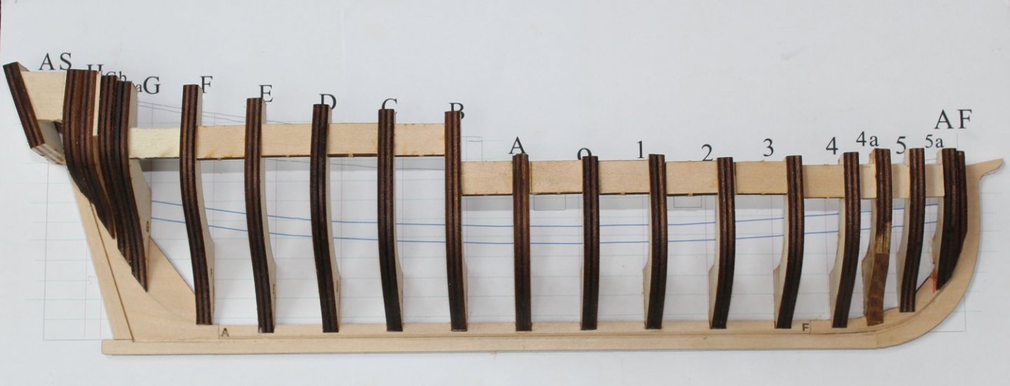
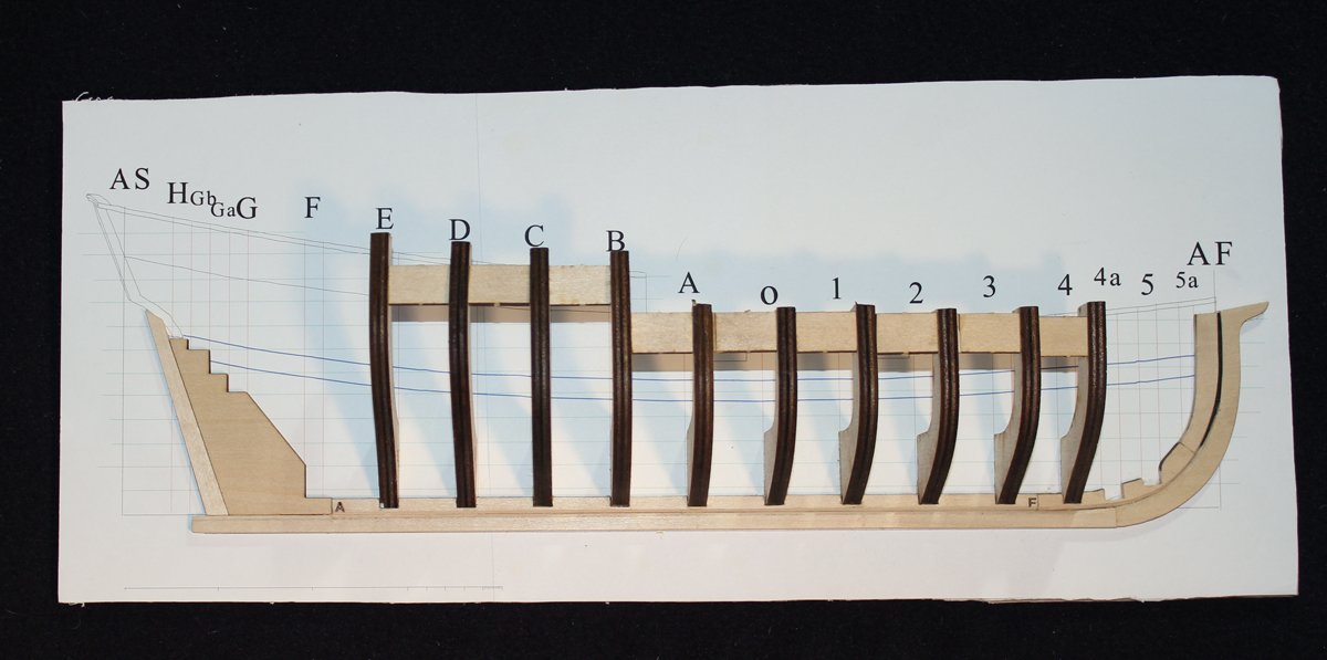
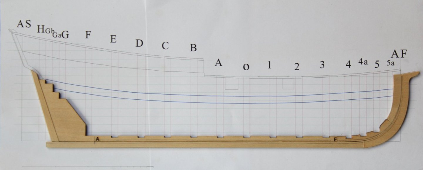
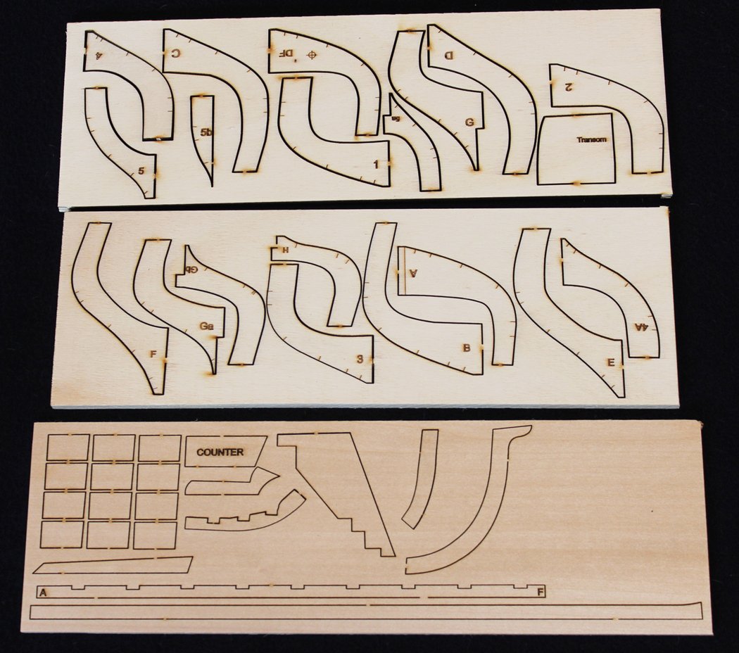
So let's get started. So far I have made four of these little ships. This will be number five. I learn something more with each one. These are the laser cut sheets that come with the kit. The top two sheets are the frames. These are 1/4" basswood plywood. This kit will have a large number of frames, in contrast with a typical kit to provide plenty of surface for gluing the planks. The bottom sheet contains the keel, stem, sternpost, etc. This is 1/8" basswood. Solid wood was selected over plywood to make it easier to cut the rabbet and deadwood. And besides, it just looks nicer. Planking material will be 3" x 12" x 1/32" basswood sheeting. And yes, you will be cutting out all your own planks. The kit will also contain the following plan. You can see that this one is in two pieces, my printer does not accept folio-sized paper. The kit plan will be one sheet. There is a scale in the lower left corner. The large divisions are five feet, the medium dimensions are one foot and the small divisions are one inch. Gun ports are show but we will not be building them (maybe on the sixth hull!). Per convention, the frames aft of dead center (represented by O) are lettered and the frames to the fore are numbered. I have spaced the frames evenly to give the plank butts a good landing place. Filler frames fore and aft will help secure the planks as their bend becomes more severe.
- 167 replies
-
- 31
-
-

-
Thanks, Tim. We will have the costs determined shortly but one of our goals is to keep this well within anyone's budget. The frames will be 1/4" plywood; the backbone and planking will be basswood.
-
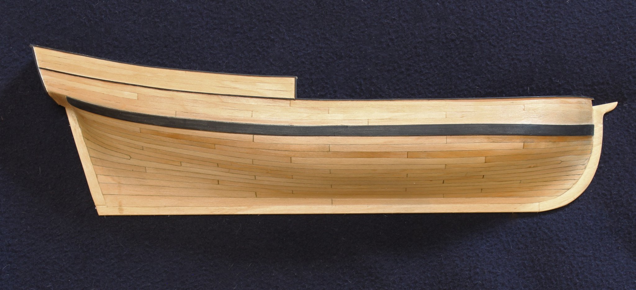
The Guild is an educational organization, dedicated to providing our members with the knowledge to improve the quality of their model ship building. One of the most frequently asked questions on MSW, from both novices and old hands, is "How should I plank my hull?" With this in mind, I have developed a half hull project to teach even the first time builder how to properly plank a hull. First, I want to thank Mike Lonnecker for help he has given me throughout the development process. Later this month, the NRG will beginning selling the kit for this planking project. It will include all of the wood and plan. The manual will be a download to help reduce costs. The photo shows the finished project. As this was developed as a teaching aid, certain shortcuts and compromises to historical accuracy were taken and I will mention these along the way. So I apologize in advance to the master modelers who will certainly find some of my technique unconventional. But they work!

- 167 replies
-
- 31
-
-
Planking the hull
tlevine replied to shortgrass's topic in Building, Framing, Planking and plating a ships hull and deck
"How do I plank a hull?" It is one of the most frequent questions posed on MSW. And it comes from all levels of builders, from the total newbie to those who have several models under their belt but are afraid to take the plunge to learn how to correctly plank a hull. No one wants to ruin an expensive kit by experimenting with hull planking, after all. The Guild recognizes this; we have all been there! We are in the process of developing an inexpensive kit (actually a learning aid) to specifically address the need to learn how to plank a hull correctly. Our goal is to have this available to all regular and associate members of the NRG by Conference time next month. I will be starting a build log in the scratch build area entitled Half Hull Planking Project and our intention is to turn this into a group build as soon as we start shipping. The photo is of my prototype kit.
- 9 replies
-
- 16
-
-
Duplicates for Sherline Lathe
tlevine replied to John Rose's topic in Modeling tools and Workshop Equipment
I also have the Vandalay duplicator and never had much success with it. -
HMS Winchelsea - Special Offer
tlevine replied to kurtvd19's topic in NAUTICAL RESEARCH GUILD - News & Information
You only have until Sept. 30 to get the free download of the HMS Winchelsea by joining the NRG or renewing your membership for 2 years. That's only 10 days from now. -
Please remember also that the Moderators are all volunteers. They resolve issues related to bad posting locations, spam, inappropriate behavior by members and removal of outdated postings. They also do other behind the scenes work that the general membership is unaware of. To also expect them to constantly sift through build logs, searching for the ones which have not been updated in over a year, is not realistic. And as Mark said, the Moderators have no way of knowing if a build is abandoned or temporarily on the shelf.
-
Jack, does your set include the figurehead?