tlevine
-
Posts
2,022 -
Joined
-
Last visited
Content Type
Profiles
Forums
Gallery
Events
Everything posted by tlevine
-

Swan-Class Sloop by Stuglo - FINISHED - 1:48
tlevine replied to stuglo's topic in - Build logs for subjects built 1751 - 1800
Keep going. Your skills will continue to improve with practice and patience. Whenever I look at one of my models, all I see are the flaws, not the overall beauty in the end result and the joy (frustration/angst) of its construction. -
I started building this model in the mid-80's. Like yourself, after the hull was built, I decided that the plans were problematic so the rest was scratch built. It was never finished because I realized how much I hate rigging, especially at this scale. I hope you finish yours. Why Esmeralda?
-
Thanks for looking in everyone. Yes, Greg, those fashion pieces gave me fits. As I recall, I made them four times. Hopefully the starboard side won't take as long!
-
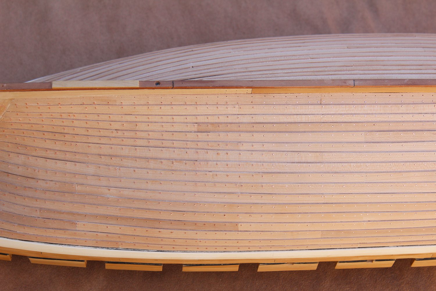
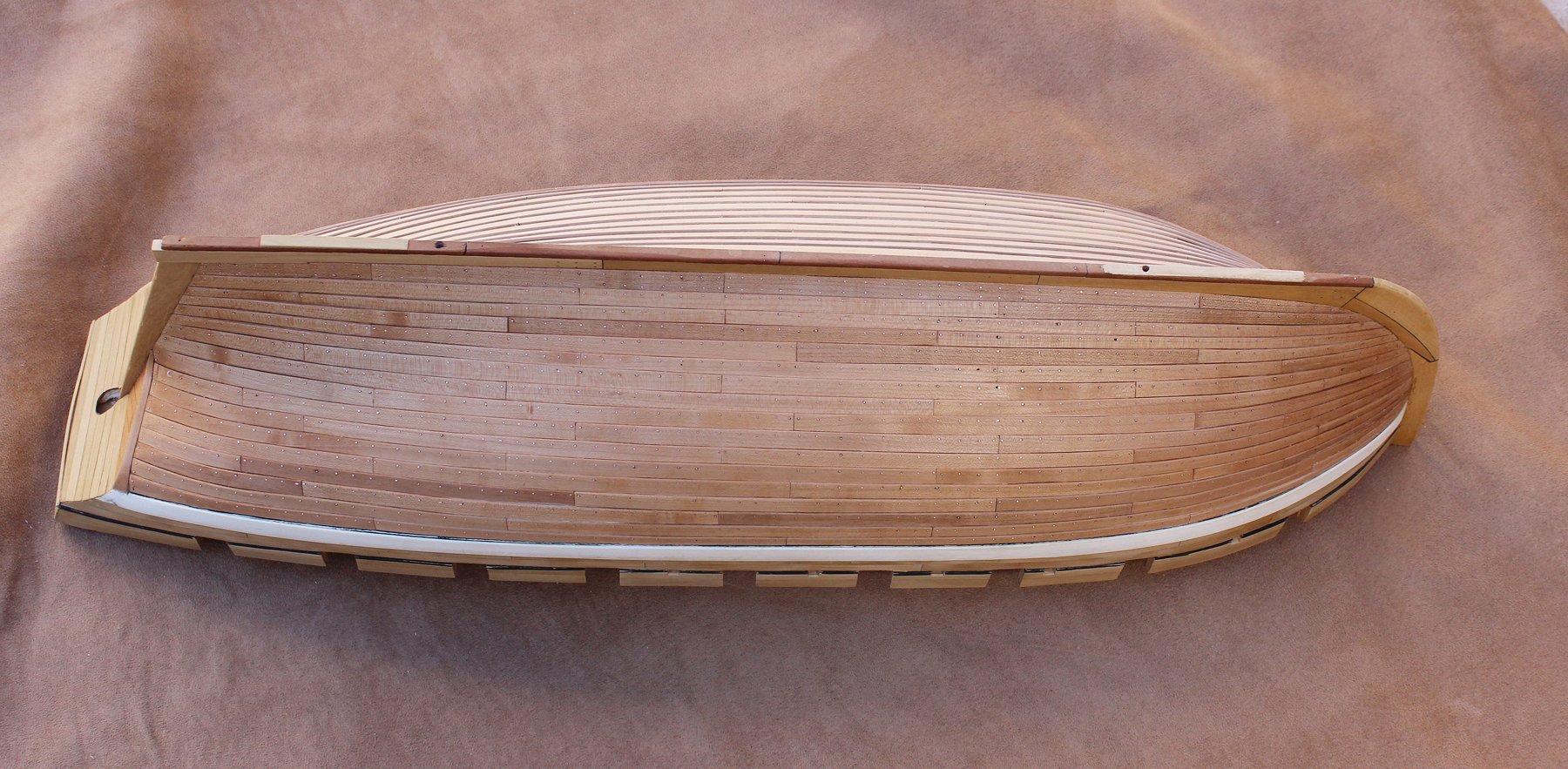
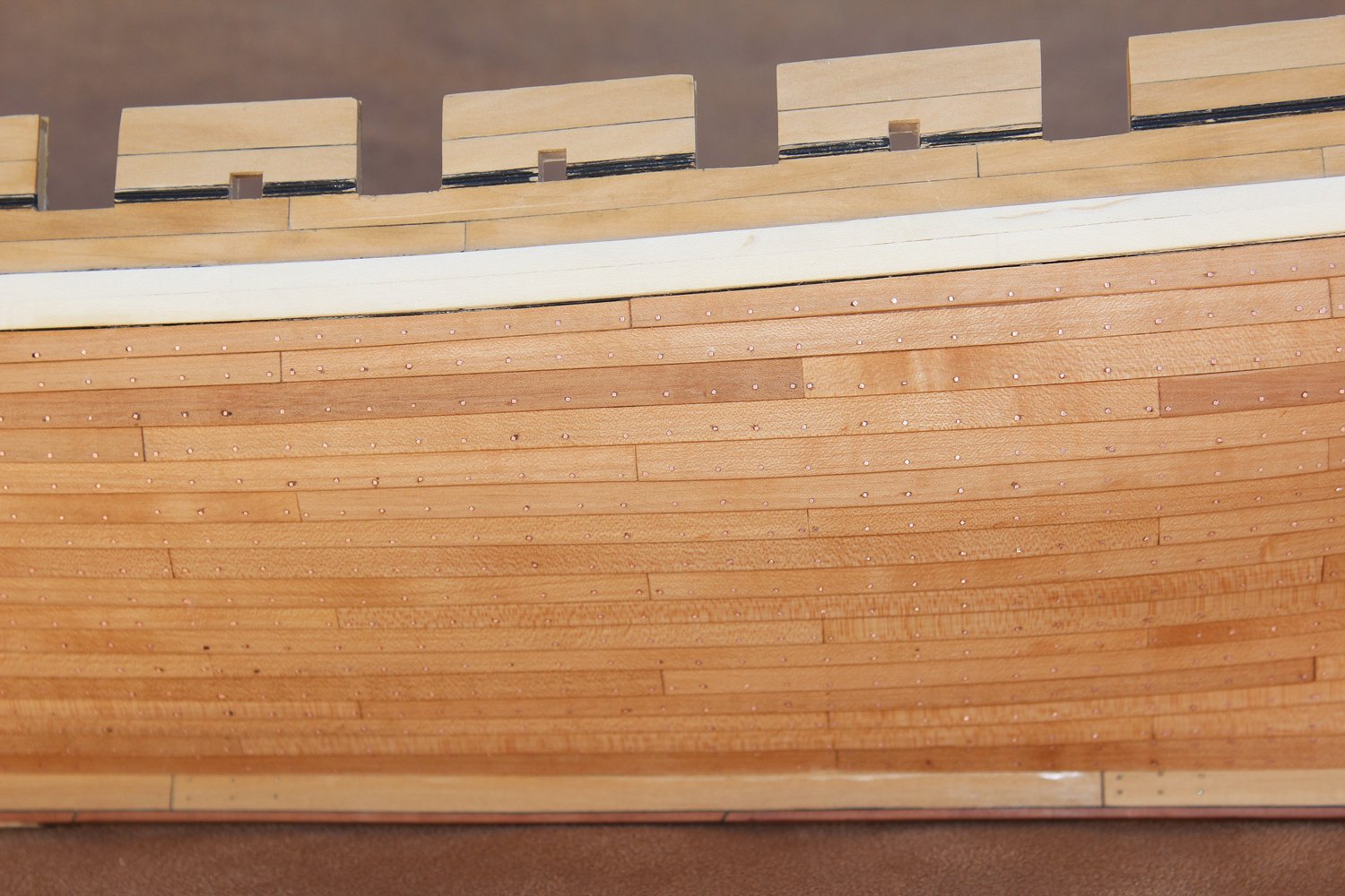
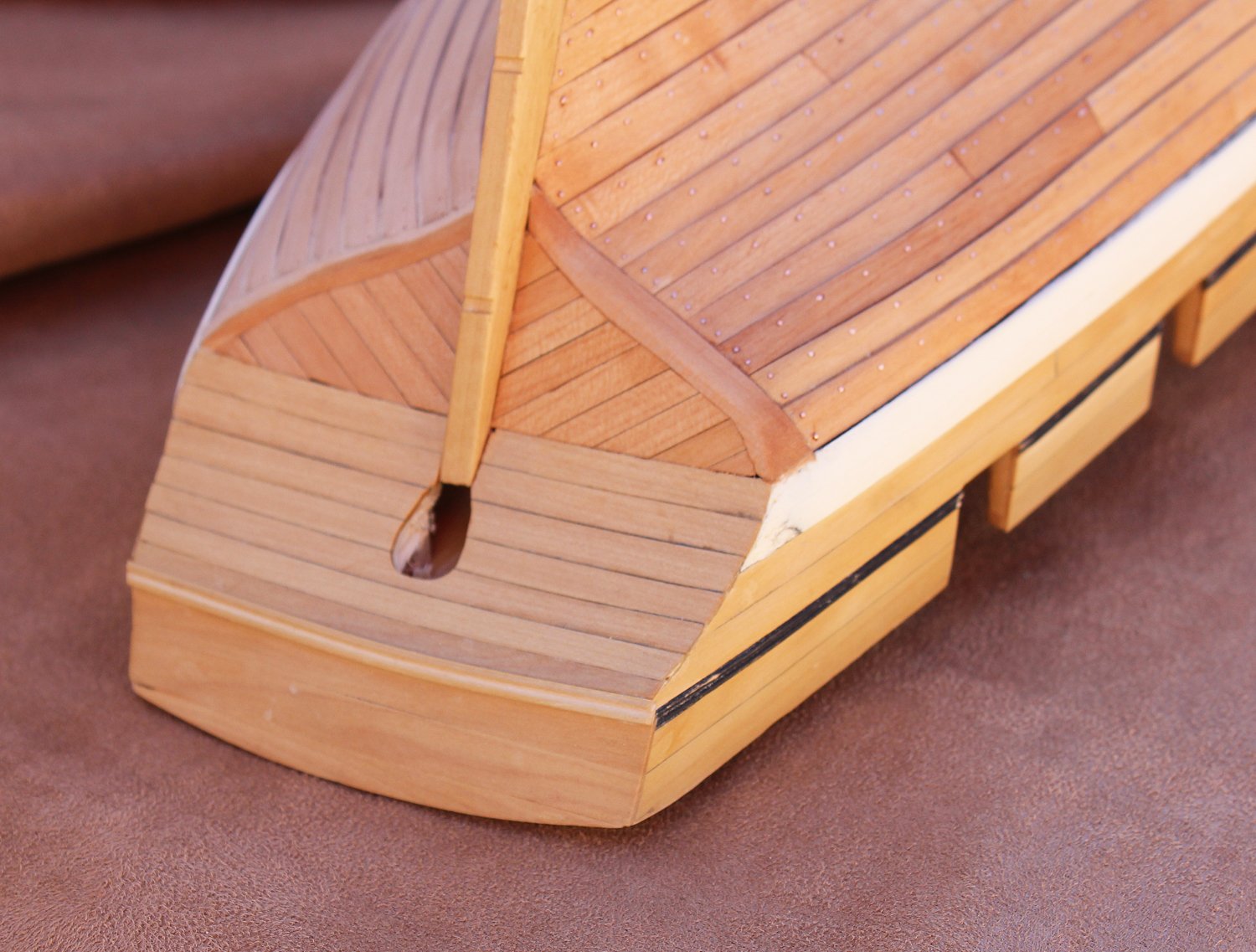
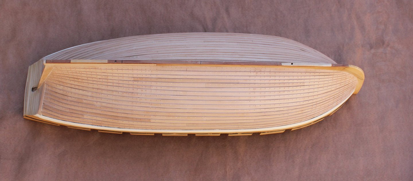
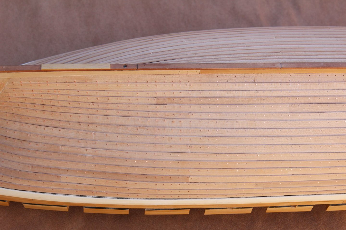
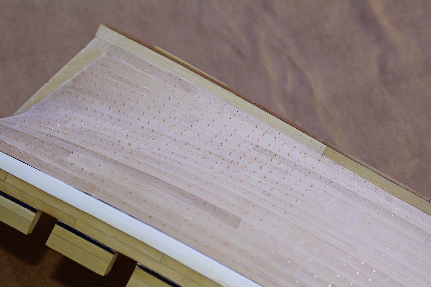
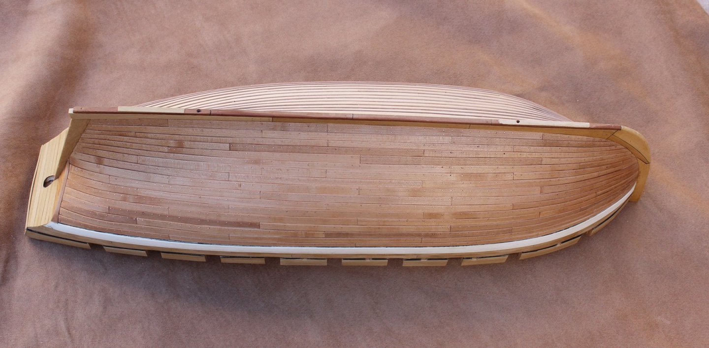
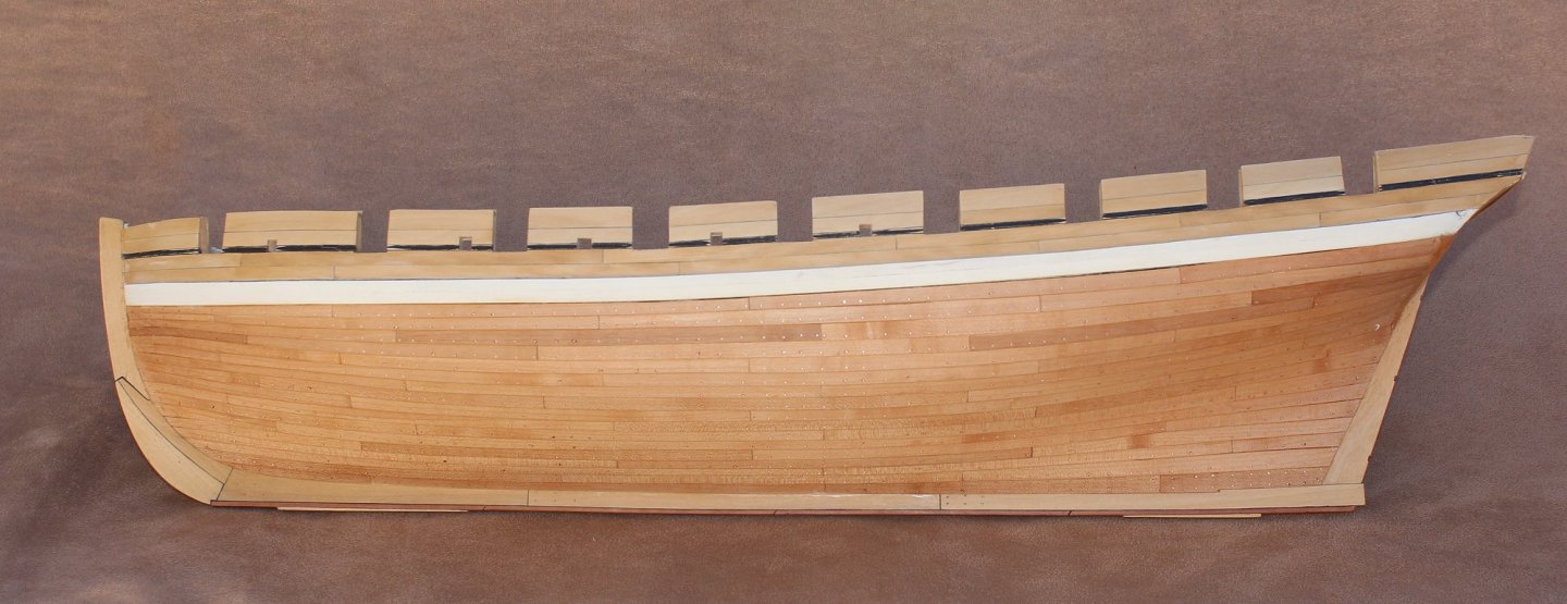
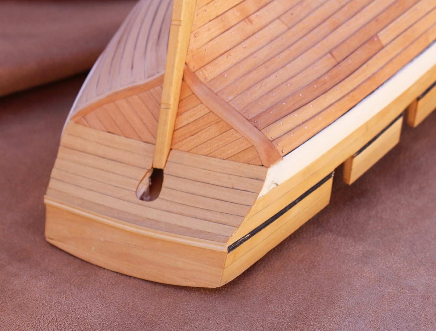
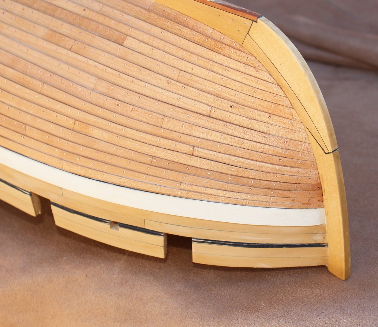
I have finally finished installing the rivets on the port side. As these would have been hand forged, I used square copper wire fit into a size 77 hole. After all the wires were inserted, the hull looked like a porcupine on a bad hair day. In the photos, I have started to flatten the heads using a flat file and rotary sanding disc on the Dremel. Once all the heads were flattened, I finished up with 400 grit sandpaper. Once the sanding and filing was completed, I put a coat of Watco's on the finished side. After both sides are completed I will add a second coat and then paint the wale. Over time, as the pear darkens, there will be more of a contrast between the castello above the wale and the hull below.

- 277 replies
-
- 34
-

-
It is wonderful hearing from you. Sorry to hear of your real life problems. Wishing you the best in 2021. Hopefully you will be able to resume Kingfisher soon.
- 1,207 replies
-
- 4
-
-
- sloop
- kingfisher
- (and 1 more)
-
It has been a while since the last post. Putting all the bolts in the planks is a right royal pain in the you-know-where. At this point I am half-way through one side. Once the side is done, I will put up some photos.
-
It isn't the first time and it certainly won't be the last! 😁 Seriously, Stephen, I am more than happy to answer any questions about the half-hull kit. Let me also encourage you to join the Guild. The quarterly Journal is a good source of modeling information as well as maritime history. And as Ryland says, members receive a discount on all the products in the store. But the Guild is much more than that. It is an organization comprised of like-minded individuals who want to promote and enhance our hobby of model ship building.
-
Take a look at this post to show you how to set up a build log, Richard.
-
Richard, where is your build log?
-
Compound Plank Bending
tlevine replied to Neil10's topic in Building, Framing, Planking and plating a ships hull and deck
Bob, I never said boiling. I said low heat. It heats the saucepan and the water adds weight to prevent tipping. Back when I was a teenager I used a curling iron all the time...on my hair. Got burnt more times than I care to remember. But we all have our unique techniques. -
Compound Plank Bending
tlevine replied to Neil10's topic in Building, Framing, Planking and plating a ships hull and deck
Might I suggest various diameter sauce pans instead of the rolling pin. It is much easier to secure the plank to the rim of the sauce pan with clamps or bull-dog clips than to a solid surface, such as the rolling pin. This works well for me. 1. Secure the end of the plank to the rim of the sauce pan. 2. Put a few inches of water into the pan and put the pan on low heat (this will warm the plank without much risk of getting burnt). 3. Gently bend the plank around the pan with one hand while using a hair dryer in the other hand to supply more heat and airflow. 4. Overbend the plank to compensate for springback. 5 Once you are happy with the curve, clamp the other end of the plank to the pan, turn off the heat and come back when it is completely cool. Whenever you are trying to bend a strip of wood, test bend it first to see which direction it is "happier" bending. Otherwise, you will end up with a lot of splintered wood. -
Your water stain is probably a glue stain. If so, it has most likely soaked into the wood. Why do you heat the plank after gluing? Is it possible to remove that plank without damaging the surrounding planks? If you used white or yellow glue, isopropyl alcohol will dissolve the glue securing the planks to allow you to remove and replace them.
-
May I also suggest you take a look at the other Swan class builds. Putting spacers between the toptimbers made the hull quite solid. In particular, check out Dan Vada's Fly.
-
Dan, never worry about pointing out an error. The drawing in Goodwin's Alert is wrong...no confusion there. Thanks for the reference. I will try and get a copy.
-
That is part of the beauty of this craft (no pun intended). There is always something more to learn. My only regret is that the incorrect information will still be out there for someone else to take at face value.
-
Thanks for the article, Greg. He obviously did not follow Goodwin's drawing. Happily, I only had four rows completed. They are gone now. I used so little CA to apply them that with some sanding, no glue marks have been left behind.
-
That was really bad, druxey. I guess that I should not have relied on just one source. I have not found any other sources that confirm Goodwin's approach. Thank you, Dan for bringing this to my attention. In a way this is a blessing. Those little copper circles are a pain to install. I just hope I can remove them (and the adhesive) without causing any damge. To say that I am not in the mood to replank the upper four rows would be an understatement.
-
So what I am doing is wrong, if I understand this correctly. There would only be a square copper head visible on the outside of the hull? Is Goodwin incorrect in his depiction of interior and exterior roves or was that technique specific to Alert?
-
Druxey, then what is on the outside? I have drawings showing roves both under the bolt head and internally, where the bolt is clenched.
-
Greg, the bolt is only 0.5 mm (scale 1") in diameter and the rove is 1.25 mm, so their rivets would be significantly oversized. I will definitely try not to achieve step 6. But if I act strangely at the Annual Meeting, you will know why.