HOLIDAY DONATION DRIVE - SUPPORT MSW - DO YOUR PART TO KEEP THIS GREAT FORUM GOING! (Only 20 donations so far - C'mon guys!)
×


garyshipwright
-
Posts
927 -
Joined
-
Last visited
Content Type
Profiles
Forums
Gallery
Events
Everything posted by garyshipwright
-
 More, I need MORE. On the other hand I can wait and outstanding job Michael. Its always a pleasure to see your updates. Gary
 -
Thanks Daniel, Ollie and Francis. It really makes one fill good to hear all of the nice comments from every one. Sharing her build with you folks is has much a joy as building her. Thanks again. Gary
-
Your very very welcome Robin Hi Mark and thank you. I ran across the tubes between the pump cisterns while researching their make up. Doesn't seem that not all of the cisterns had two dales per side. As far as your helm port sir, am sure you will figure it out. One difference I noticed is that I ran my stern timbers all the way up and you cut your's off at the quarter deck. I found this easier getting them align and hope that when I finally get around to this part that they will help me get every thing stright and level. Gary
-
Hi Mark. You do seem to be well on your way to having a outstanding and beautiful stern and walk sir. It does take awhile to work this out and am sure once you do it will be a good lesson for every one in the process of building the ships stern. Gary
-
Thanks Robin, Michael, and Pat. Its allways nice to hear a good word from you folks. Robin the ideal came from Daniel Victory build, HMS Victory by dafi - To Victory and beyond, in the kit section, who deserve's the credit on this one. If you go to post 157, page 11, he will show you how he made up the bucklers for the end of his pump dales. The bucklers make a lot of sense since thats what they used around the hawse holes and am sure they kept out a ton of water. The other thing about them is it would help lock the ends in place so the pressure of the water going out would keep them from moving all over the place, much like turning on a water hose and not holding on to the end of it. Gary
-
Thanks Tim, Robin B, Alan and all the likes. Tim I do have to go to the store and buy grog every couple of days, those guys can put away some grog thats for sure. Robin as far as I know the cranks or brakes were made to be locked together when needed and stored when not. Most show it because its a nice detail to show. As far as the scupper holes they probably could have done a couple of things. From most of the research I have done on them they probably had leather flaps on the outside that closed off the opening for most of the smaller scuppers,acting like one way values, and at least for the pump dales scuppers, on the inside fitted with bucklers, flat boards to prevent water from coming in, along with the leather flaps on the outside. From what I can tell most were made up of wood lined with leather or lead pipes that seem to have a curve in them or be at a 25 degree angle from the deck to the outside hull. The plans that are shown at the NMM shows the pipes as being curved and made in two parts to be hooked together. I remember reading about discharging straight on to the deck which would make sense being that there was more scuppers that the water could flow to. Did come across one plan and it had a plug that they used to plug up the scupper with. If you want to look at this it is plan number ZAZ6880. Maybe it was used to help keep the trash out when they were doing field day.Hope this answer you question Robin. Gary
-
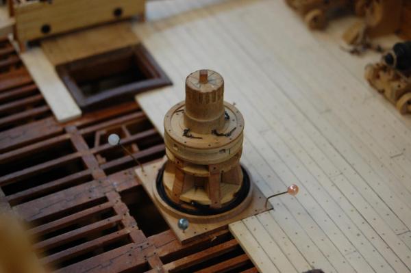
Thanks Jay, David B, druxey and Sos. Jay the hands are not to bad, and the misses does keep me busy around the house fixes this and that. As far as the capstan and pawls, yes the one at the bottom. As far as the history on them, John H Harland wrote a book on them, called Capstans and Windlasses and talks about the drop pawl more or less replacing the sliding pawl and mention a fellow named Eckhardt. Another place that I found more information on the 1770 date was found in his book and in Sea Watch book Message in a Model, Ab Hoving. It talks about a fellow named Eckhardt who was known at the guy who invented one of the biggest improvements to the capstan. The invention was tested on the English Ship Defiance, a 64 gun warship in 1771. Of course his invention didn't catch on but his invention did have drop pawls. Also shown in Goodwin book, Constructing the English ship of war, which mine is out in the workshop, shows drop pawls on capstan earlier then 1770. Am not sure of the page number and as soon as I get back out there will add to this post. Do believe that druxey mention a article in the NRG but can't remember which one at the moment but will add that to, that is as soon as I can find it. Gary
-
Thanks Jay and Mark. It does seem that with the planking done, it put me on a heading to be able to add the rest of the parts and pieces to the deck. At the moment am trying to figure out how to take better picture's of her. Seems that some of the items are not in focus so figure I would break out the trypod and take a better picture. Found the trypod but would you believe it if I told you that the quick release plate is missing. Going to have to make a new one and then I can maybe get a better picture. Thanks again guys. Gary
-
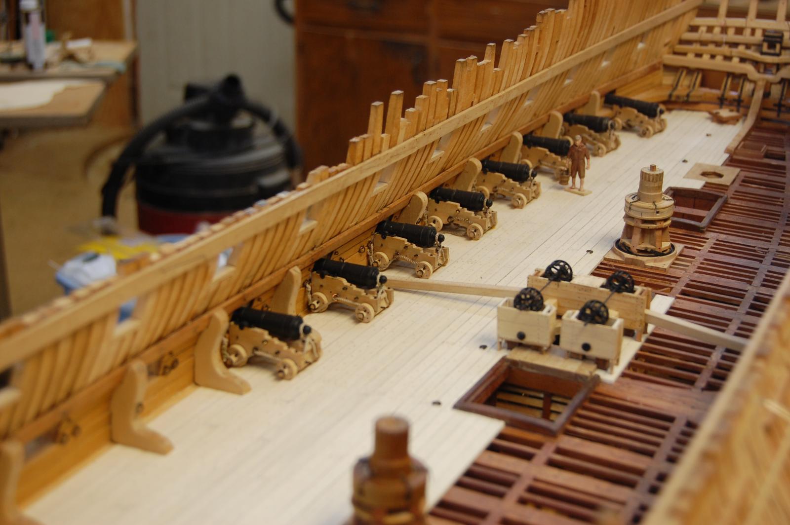
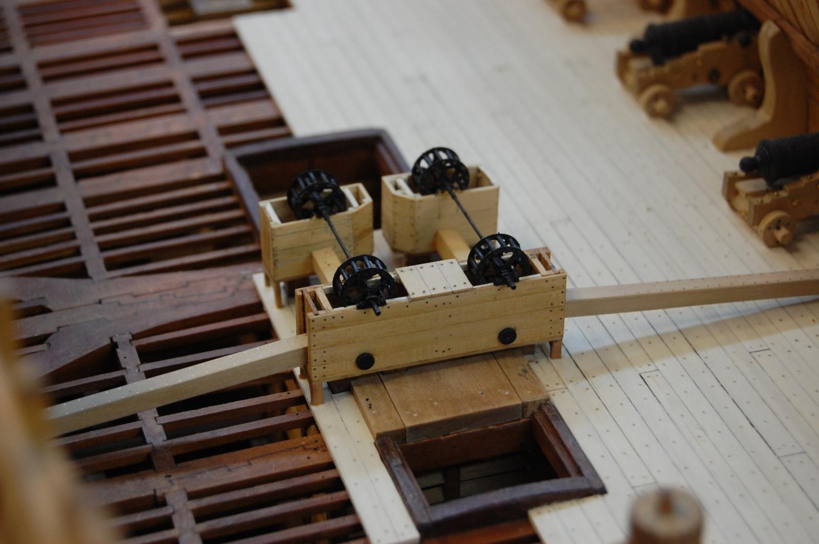
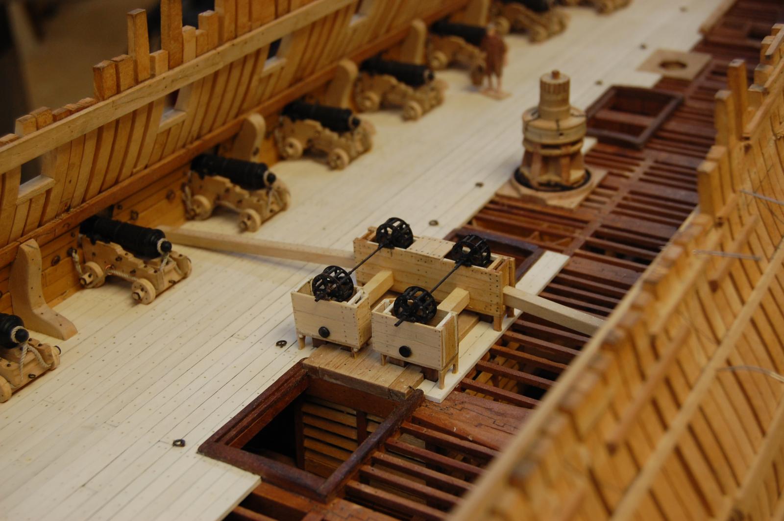
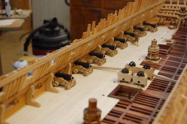
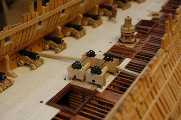
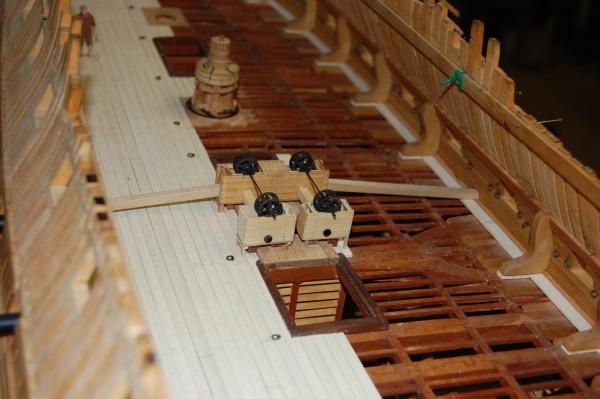
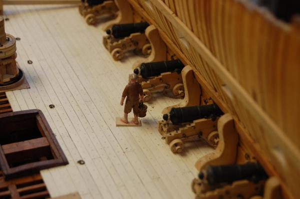
Well guys figure I couldn't let February end with at least a small update. Have been working on the cannons and a few other items such as the chain pumps, capstan along with redoing the helm port and upper deck transom. It seems the more I looked at those items the more I wanted to redo them and seems that that's what I did. Also added three more of the chain pump sprockets and not hoods along with the chain pin's for the capstan and drop pawl's. Did Montagu have the drop pawl's, maybe yes may be no, butt does seem that they were being used in the fleet as early as 1770 so figure I am safe adding them. Enjoy the photo's folks. Only 6 more 32 pounder's to add and the guns for this deck will be done. Gary

- 835 replies
-
- 34
-

-
Alan It does seem that the NMM has a contract for both, the Bellerophon of the Arrogant class of 1758 for the Bellerophon of 1786, Loc-GK11, Box-1, No-114 and the Elephant also Arrogant class 1758, Elephant of 1786 Loc-GK11, Box-3, No-135. Should be a help in ordering them and give you much needed information on sizes of timber such as the frames, keelson, and other main timbers. It is also great when you can even find one for the ship your building Gary
-
Looks out standing Nils and talk about a lot of parts and pieces. The metal work is out standing and must have took forever but looks good. . One thing I noticed is the crew and every once in a while you have them working around the decks and wheel. Any chance of knowing where you press them from? Outstanding Nils. Gary
-
Sorry Alan should have include this. Which one is the most important tool on the desk? Gary
-
Ok Alan which one? Gary
-
Hi Remco. Simpley outstanding sir. You giving me some great ideals for Alfreds kitchen when I finally get there. . O by the way, do believe it looks like some one took the silverware. Gary
-
I would probably say the beer. Gary
-
Mark one of those plans do show that the helm port transom could be moved forward but am not sure what plan it was. Went and took a look and its the Vengeance, J3250. Believe that the standard has been notched so the transom will fit. Mark do believe you mention that the transom is 10 inches wide. It should be 10 inches deep, accorden to the contract. Steel also says that its post to be 10 inches deep but gives the moulded on the fore and aft as broad as may be had- 1 foot 8 inches and broad upon the clamp 1 foot 4 inches Gary
-
Nice drawing Mark. You could also go and look at the plans J2683 Goliath which has a stern view showing the shape of the HPT(Helm port transom), also the Vengeance of 1771, J3250, Ramilies of 1785, J3209 and Bedford 1775, J3365. Gary
-
Micro drill holders
garyshipwright replied to Trussben's topic in Modeling tools and Workshop Equipment
Thanks Michael. Have thought about the small one at Micro Mart, sells for about 35 dollars or so. Gary -
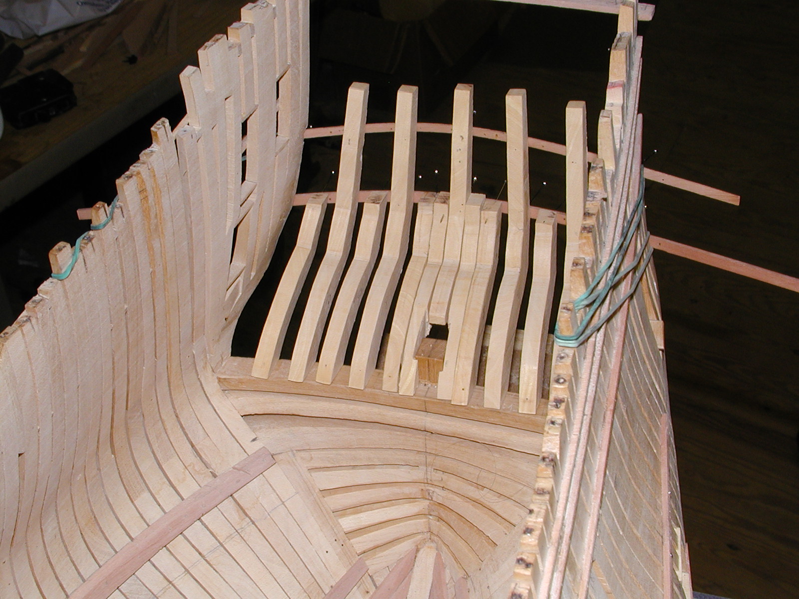
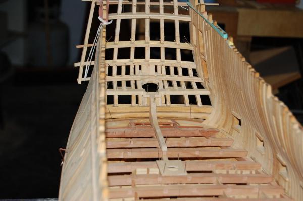
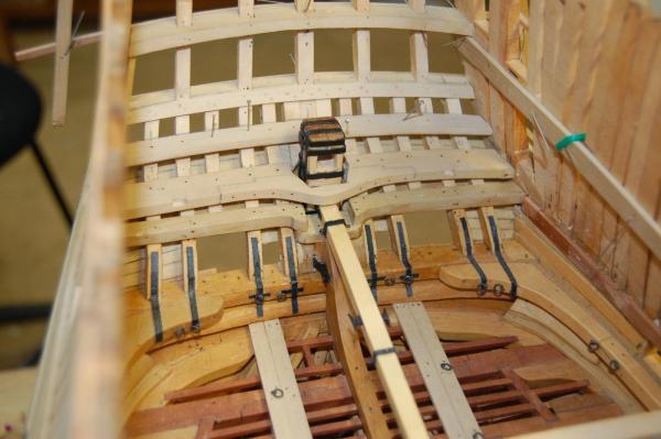
Hi Mark Good drawing sir but I believe that the helm port transom would have intersected on the forward part of the stern post. Other then that sir I would say your drawing is right on. Not one of my better views of the stern Mark but should give you at least ideal's about how I approach this on my stern. Since these photo's, I didn't like my helm port transom and have taken it out. At the same time a few more items may come out and be replaced also. Guess items do have a way of coming back to haunt you untill you just have to change them out. Gary

-
Hi Mark. I took a look at the photo's sir and the one that show's the side of the stern post, the helm port transom, does run in to the side of the stern post but isn't the way it was done in full size as far as I know, from the plans that I have seen. The stern post would have been notched out for the transom to fit on top of it at a height of 3 inches below the tiller I believe. I think that the builder of the model didn't notched out the post and just cut the transom to fit on either side of the post. This is one of those items that is a real bear, to fit in one piece. Another item that isn't shown in its proper shape is the gun deck transom which usually has a round up to it and other then the wing transom the rest of the filling transom are all flat across the top. As far as the upper deck transom I do believe that on the Bellona model, it does show it shaped right, with the center cut out to fit a round the rudder. If you did go with the forward beam you would still need a upper deck transom for the end's of the planks to land on. Do wish we had some photo's showing what those items looked like on the inside of that model, which would be a big help in figuring out their shape. Do think the shape in your drawing is close to what probably was used. Some thing that does help on the helm port transom and figure out its height in the middle is that the standard(knee) that fitted on to the front of the stern post, the upper arm top height was also the upper part of the top of the helm port transom. Since your builder her like the model then fitting the helm port to the side of the stern post would be well in line, that and building the deck transom as you have it drawn, fitted to the counter timbers. . Gary
-
Hi Mark Your sketches look good sir as your sketches always do but from the research on this part there are a couple of items that seems to be questionable. One would be the upper deck transom. From looking at plans and the contracts it states that it was ten inches deep, scored and bolted to the counter timber. As far as a rabbet for the deck planking here, plans show that the planking run's all the way back to the outside edge of the stern counter timber's, butting up against the lower counter moulding. The only deck transom that is mentioning as have a rabbet on its forward edge is the round house. It does seem that if the other transoms had one it would have been mention in the contracts. Why only mention the one and not that others and at the same time only show the round house transom on the plans as the only one having one. The other item is the helm port transom. Going by what the contracts say about this item is that it is to be 10 inches deep, scored and bolted through the counter timbers, to give it no more cast than necessary to give room for the tiller (which is to have 3 inches play above and below, between the deck and helm port transom) and stern ports. It also goes on to say that the cast part of the transom, were the wood is apt to spring, to have two small bolts drove down from the upper side, and clenched on the under side as close as may be to the middle part on which the tiller traveses. This tells me that there was one piece that was bolted down to the top of the stern post and then was cast up to make up the top of the gun ports. My way of looking is which one would give you more strength. When looking at the photo of the Bellona stern you can make out the cast part of the helm port transom sitting on top of the stern post. Just more to think about Mark, but am sure which every one will look as good as the rest of her. Gary
-
Thanks Antony. Is there any way to get a plan type look at it sir? It could make a good detail addition. Gary
-
Mark that looks good sir and do agree with you on working from the outside to the inside. When I laid Alfred's gun deck plank's, I went from the outside towards the middle and from the bow to the stern. A whole lot easier fitting the plank up against the water way then fitting it after every thing else is laid. Gary
-
Hi Guys. Have to agree with you on what the purpose of the king plank was for, but only one thing comes to mind about it. If the deck has hatches down the middle of the deck and the king plank is cut up by these, where is the strength of the king plank. Wouldn't thicker planks on either side of the hatches , recessed in to the beams and not being cut in two have more strength, then a king plank cut up in to short pieces in the middle of the deck? Just a thought on it. Gary