HOLIDAY DONATION DRIVE - SUPPORT MSW - DO YOUR PART TO KEEP THIS GREAT FORUM GOING! (Only 20 donations so far - C'mon guys!)
×


garyshipwright
-
Posts
927 -
Joined
-
Last visited
Content Type
Profiles
Forums
Gallery
Events
Everything posted by garyshipwright
-
 Thanks guy's. I went back through the log and redid the photo's. Been working out of town, so sorry about the delay. Gary
 -
Thanks Siggi. I really really like the detail and gives me ideals about adding some of this to Alfred's gun deck. Gary
-
Good job Siggi and a fine job bringing her deck to life. Now I have a question about the lanthorns and other fine items, and was wondering did you take any pictures of them as you was making them?. Once again sir good job. Gary
-
Have you thought about just filling the holes with trunnels? When am installing parts and pieces to Alfred I usually hold the parts in place with pins and then fill the hole with a wooden nail. Just a ideal but may give you something to think about. Gary
-
Hi Guys. I finally got around to redoing the photo's. Just click on the photo and it should enlarge so that you can get a good look at the books. As druxey said it is a little dated back to the 1980's but does help one who doesn't know about them and just may want to add them to their library. Gary
-
Hi guys. Give me a day or so and I will try to put the pictures back. Can't seem to find them on the computer at the moment so bear with me. Gary
-
Richard some thing to keep in mind for figuring out the different rates was based on the number of guns they carried. Gary
-
Hi Siggi. I took a look in Adrian Caruana book, The Age of the System, 1715-1815. On page 388, He says that two inch muzzle lashings were used for lower deck guns. Gary
-
Mike I have to agree with Greg sir, the Byrnes disk sander has become one of the most commen used power tool in my shop, along with his table saw. It is really a very accurate tool and being able to reset the angles every time is great. Get one, you won't regret it. Gary
- 968 replies
-
- 1
-

-
- hahn
- oliver cromwell
- (and 1 more)
-
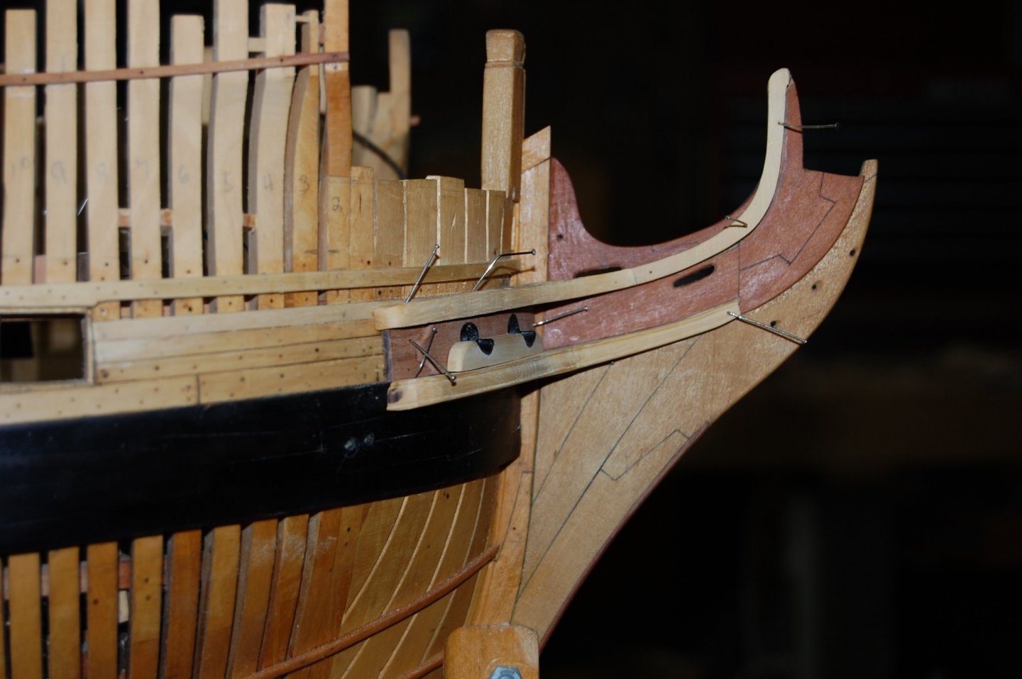
Hi Mark. Just want to say thanks for all the great photo's sir along with all the other folks photo's, they are a great help in figure out some of the items and hope you get to take more of them in the future. I did lower the leading edge of the top front rail maybe a hair or two to follow the planking behind it which does run with the sheer and used it as a stright edge. Does seem to have brought it more in line. Lowering it two much just might mess with the items above it. You are so right Mark it is the viewpoint.One can look at it from a thousand view's and still not get it right, having your eyes and others as another set of eyes really help's to see what one doesn't. I found out some times leveling something depends on how other items look around it which sometimes are not level. Here is a old and new showing the top rail forward edge. At the moment it is just pinned in place in case I need to take off another hair or two. Gary
- 835 replies
-
- 22
-
-
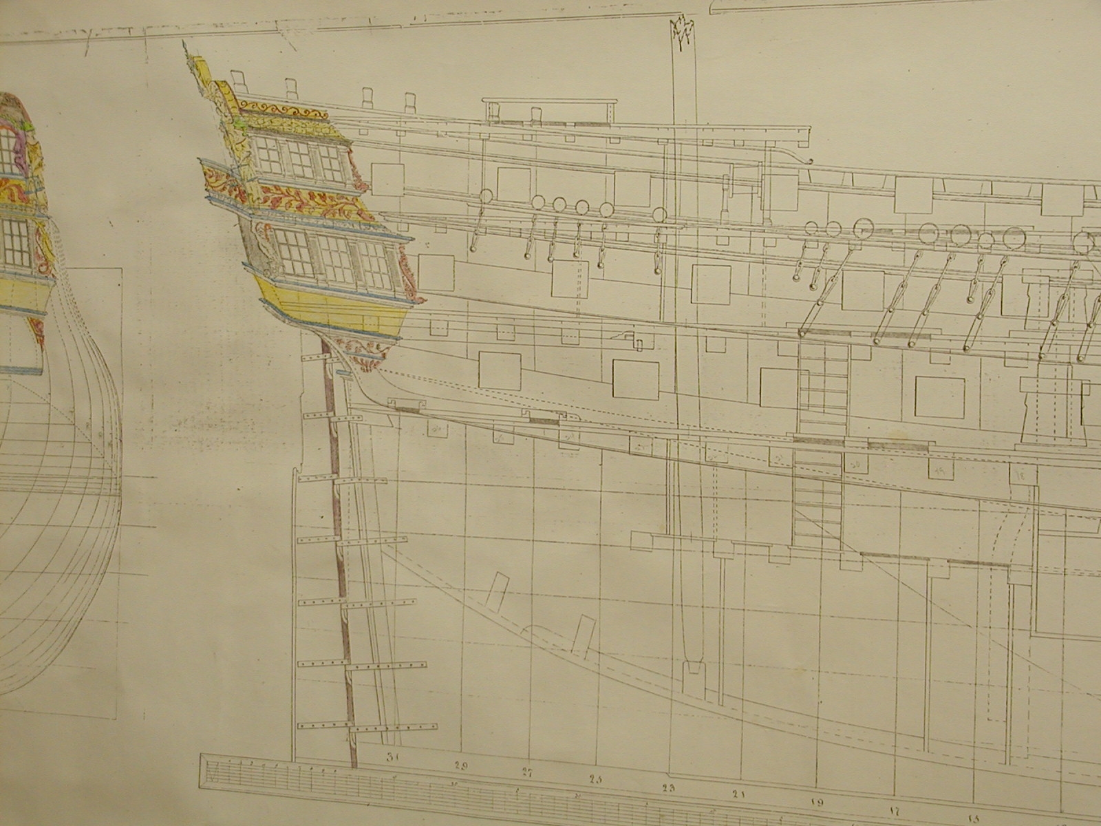
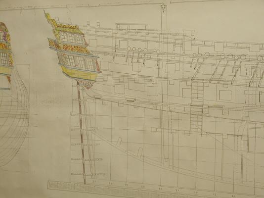
Hi Siggi. From what I can tell her rails are running with the outside sheer. Here is a photo from her plans and another photo showing what I built. Easier to tell when they are side to side. Might just have to take another hard look. Siggi it might be the angle I took the photo at, maybe a little on the high side. Gary
- 835 replies
-
- 11
-
-
Thank's every one and all the likes. Alan the planking on the stern it self is ebony and the curve was not to bad, but when I tried it on the bottom pieces of the quarter gallery, no matter how much I soaked and heated it, it always seem to break, so I switch to pear and blacken them to match up with the ebony. One thing for sure it turns every thing black. Brian hope that the build will help you along in yours. Thanks to Mark there is some photo's of the Warrior model in the Gallery of Contemporary Models from Museums and Private collections that he has taken of the model and the best thing is he takes them through the eyes of a model builder. Should come in real handy thats for sure. Gary
-
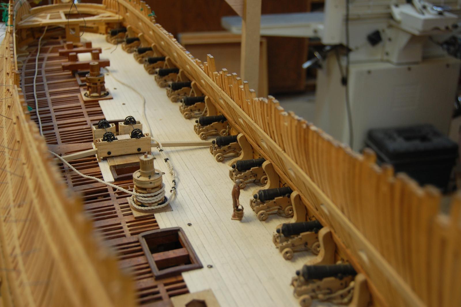
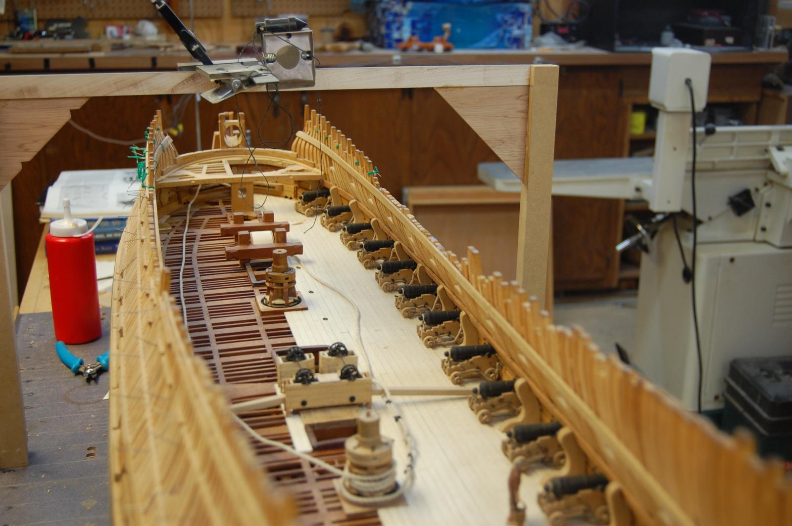
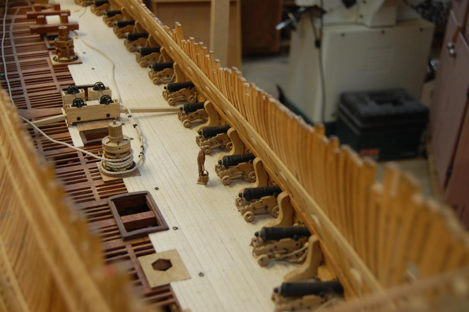
Thanks Mario and Dave. Mario your so right sir and work has kept me away from Montagu but I do look in on the site, to help me get through those times when there wasn't enough time to do any ship building. Things have eased up a bit the last month and have been working on the stern and the thirty two pounders which have all been installed and have a few more tackles to make up for them. In the mean time the stern upper and lower counter curves have kept me busy trying to get their curves just right. Seems every time I thought I had it right, found a part that didn't look just right and tore it off just to redo it. To me if those curves are not right your eyes lets you know, and every thing else is built upon those curves. So getting them right was high on the list. A make or break sort of item. Some thing that helped was the ideal that I got out of Davids new book the fire ship comet, the quarter gallery berthing piece on page 111. He talks about how he mount this on Comet so figure I would try it. After making 3 of them, I finally manage to make a port and stbd that fit the bill and this in turn help big time in getting her upper and lower counter curves to lay proper. In the process the top plank on the lower counter was a little shy on meeting the rail of the lower counter and had to make a new one. Not glueing the planks in place and held by a small amount of glue on tree nails made pulling it off a lot less nerve racking. One thing about building up the curves of the quarter gallery is figuring out the curve of them. But there is hope for finding their curve at least the one I came up with. English plans only show one pattern for this curve and that is on the quarter deck level, but is bigger then the ones that fit the upper deck. Taking their size off of the stern and sheer view and using the quarter deck pattern one can get it real close in size, which I do believe Montagu is just right. Sorry about the long delay in a up date. Gary

- 835 replies
-
- 23
-
-
Can i live without a BYRNES TABLE SAW
garyshipwright replied to shihawk's topic in Modeling tools and Workshop Equipment
Here is the ideal behind getting a Byrnes tool, weither it be his table saw or his sander, they are outstanding tools and one will get many years of happy returns on them, much like me. . Now to give you other ideals, about buying them is to become able to buy larger timbers and save money. Yes they cost up front but think of the savings, like shipping and not having to worry about having the right size piece as your building your ship. To me I enjoy working with tools and, good ones for sure, like the Byrnes table saw. Here's a question, can you walk out in your back yard, cut off a tree limb and convert it to timbers for your ship? I really like be independent for relaying on buying stuff and having to wait on things. The money saved from buying ready made timbers allows me to buy those things that I don't have time to make or that new book from seawatch. Of course some will still buy ready made timbers which I have nothing against, much like buying a kit, or a cannon, or even a light like what Chuck offers which I do ever once in a while . Does one need a shop full of tools to build a ship, shoot no, all one needs is a good knife. Isn't that what the POW builders use. That is if they were allowed one. It does come down to each of us to ask that question do I need a Byrnes table saw? For me the answer was can you get it here yesterday. O and the back yard was my mother who was wanting her holly tree cut down which I was more then happy to do. Gary -
soldering torch vs iron
garyshipwright replied to rtropp's topic in Metal Work, Soldering and Metal Fittings
little smith . Its a good one. Gary -
Hi Remco. Great work sir and have a question for you. The pins you have stuck in the soldering board, what are they and if purchase when can one buy some? I got one of these soldering boards after seeing yours but so far have not found the pins. Thank you sir and keep the photo's of your build coming. Gary
-
Hi Siggi and thank you very very much. Not being able to visit places like the NMM to view the models and how items are built up such as the stern, one has to depend on books to help fill in the pieces. Having all the carvings in place brings in to question on how the pieces underneith all fitted together before they were added. Having books like David A Swan class and now the Comet along with build logs such as yours, Mark and others, photo's like the egmont, and dragon really helps those of us that are land lock. Once again thank you sir. Gary
-
Hi Siggi Thank for posting your build and your building of your stern is a help to building Alfred's. Didn't expect to see John Franklin Egmont here but was wondering do you have any more photo's of the port side stern and quarter galleries, I have allways had a big interest in how her stern and port looked on this side but have never seen any photo's of her, and once again thank you. Gary
-
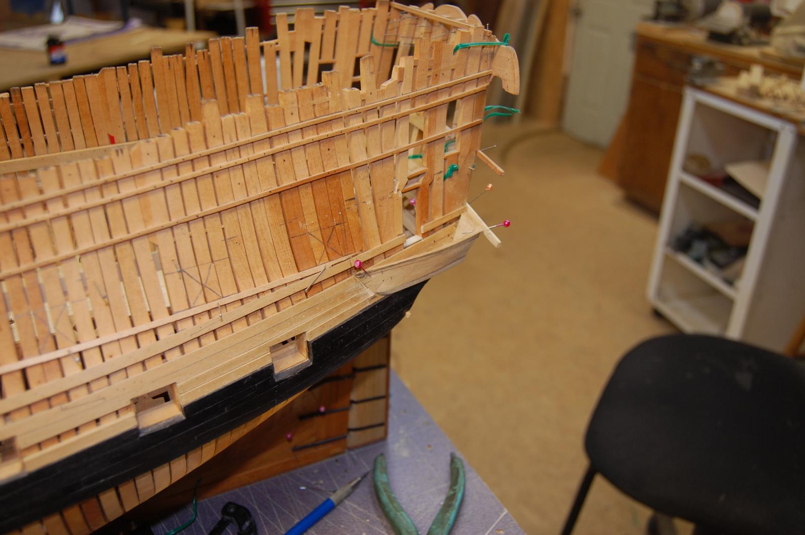
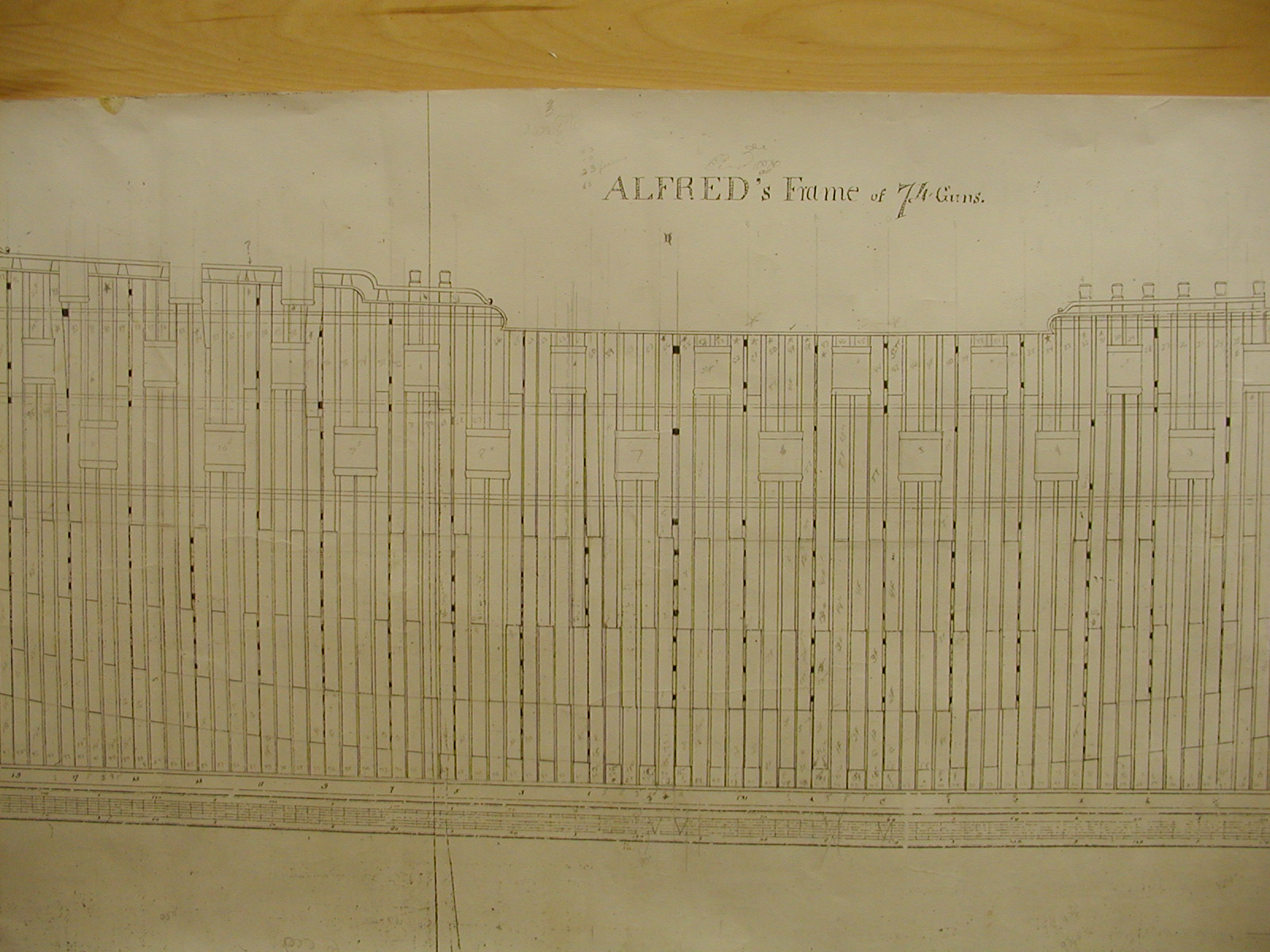
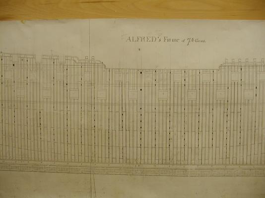
Hi Larry. Just to let you know if your building Alfred doing it Hahn way then your be framing her the French way. English ships framing at that time were built using bends, two frames whose floor and first futtock's touched but in between was filled in with filling frames, a frame built up of first futtocks, third futtocks and top timbers, or floors, second futtocks and fourth futtocks. On Alfred, her dead flat frame was made up of first futtocks with floors on both sides. As they went fwd you would have a first futtock followed by a floor and going aft you would have a first futtock follwed by a floor. Have included a photo showing Alfred in frame. A good book which will be a big help is Peter Goodwin Sailing Man of War will help fill in the gaps on how the framing was done depending on the time frame. Any more question sir and will be more then happy to answer them. Gary
-
drill press/mill decision
garyshipwright replied to peewee's topic in Modeling tools and Workshop Equipment
Yes I do believe that Sheerline is well worth the cost and enjoy ever minute I get to use mine. Tons of extra to. Gary -
Hope no one mind a stranger joining in but do agree with Ed, it does look like the joint line between the apron and stem. Gary
-
Allan all I can say is thank you, the book is outstanding and a very good addition to ones library and as other's have said is a lot easier to read then Steel and SR. The cost of them compared to your new book is a steal and should come in handy to researches and builders of ships. Thank you for this and with out folks like your self, my library would be a lot smaller. Gary
-
Thanks B.E. Gary