Hubac's Historian
-
Posts
3,314 -
Joined
-
Last visited
Content Type
Profiles
Forums
Gallery
Events
Everything posted by Hubac's Historian
-
 I'm in, also, Don. This ship has nice lines, and after your last build, I expect that you will do great things with this one. Looking forward to enjoying the process.
 -
Great tip on the spray starch, Ken. Looks fantastic. Can you tell me what the flags are made of? Cotton, linen?
-
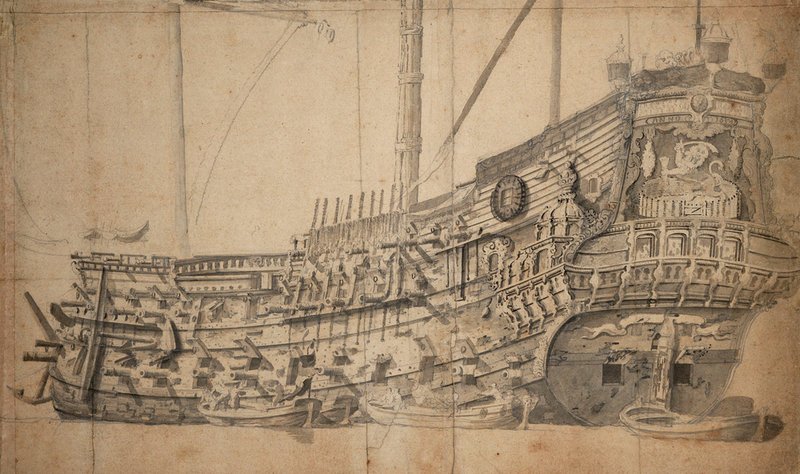
The great thing about Van de Velde, the Elder, is that he often does document the fastening of the wales, among other iron fastenings, on his early portraits from the 1650s/60s. There are several excellent portraits of post-battle, scarred Dutch ships laying in for repairs that give a fairly clear idea of the topography of a ship’s hull from this period. Later, I’ll upload a few images from my Pinterest page to show what I mean.
-
This is off to a great start, Chris. I can relate to trying to get a little quality working time in, around the sleeping times of my kids. I try to get at least a little something done, most evenings, but some nights I just don’t have it. Anyway, this is such a lovely frigate you are building, and I am looking forward to following along.
-
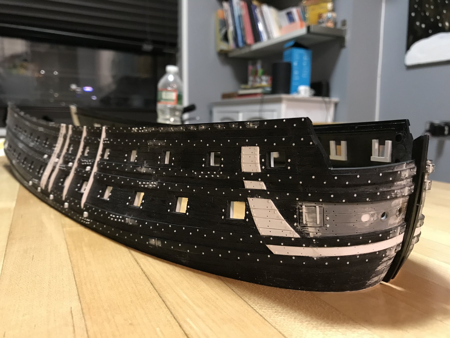
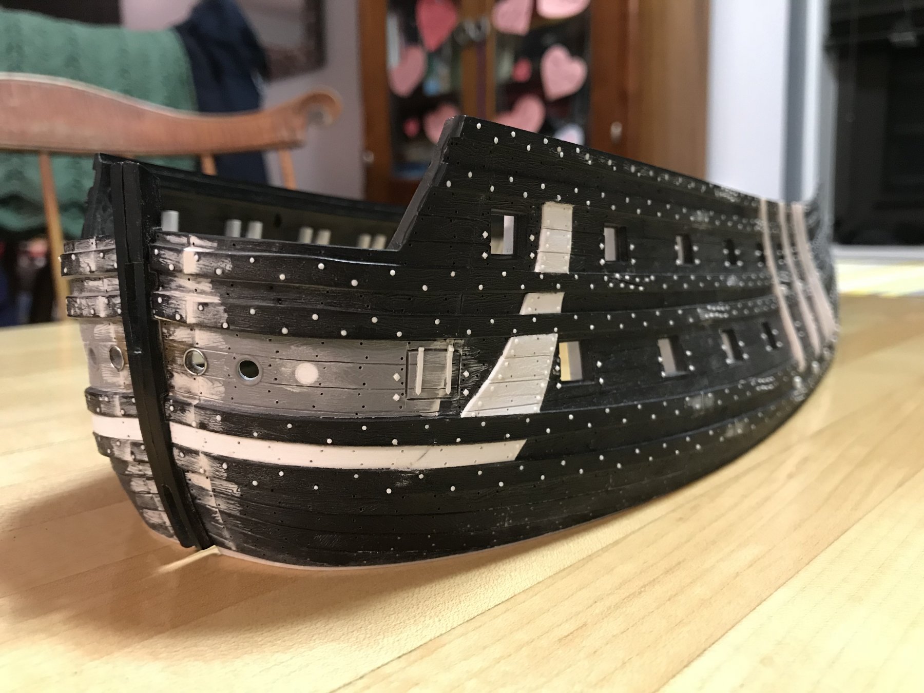
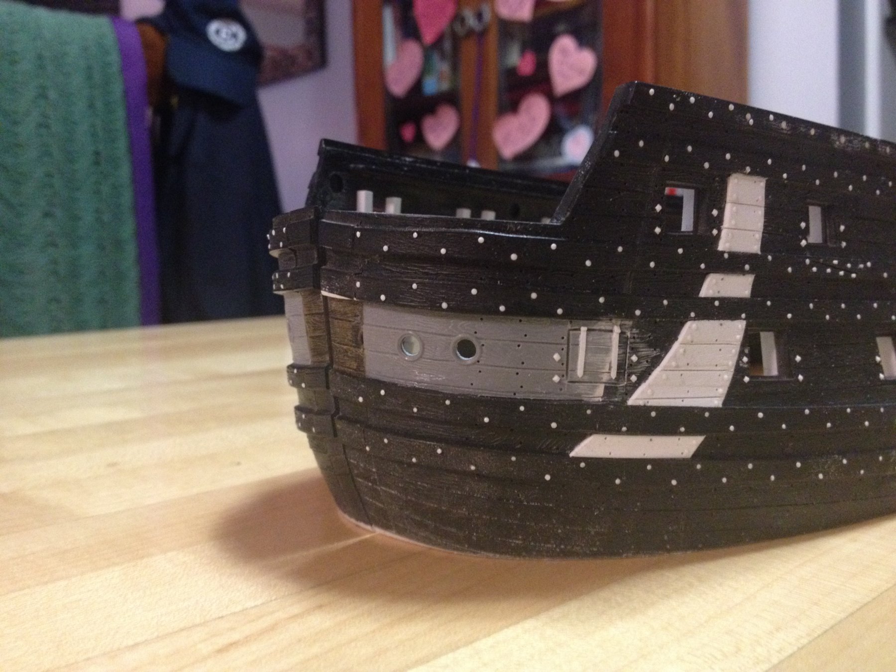
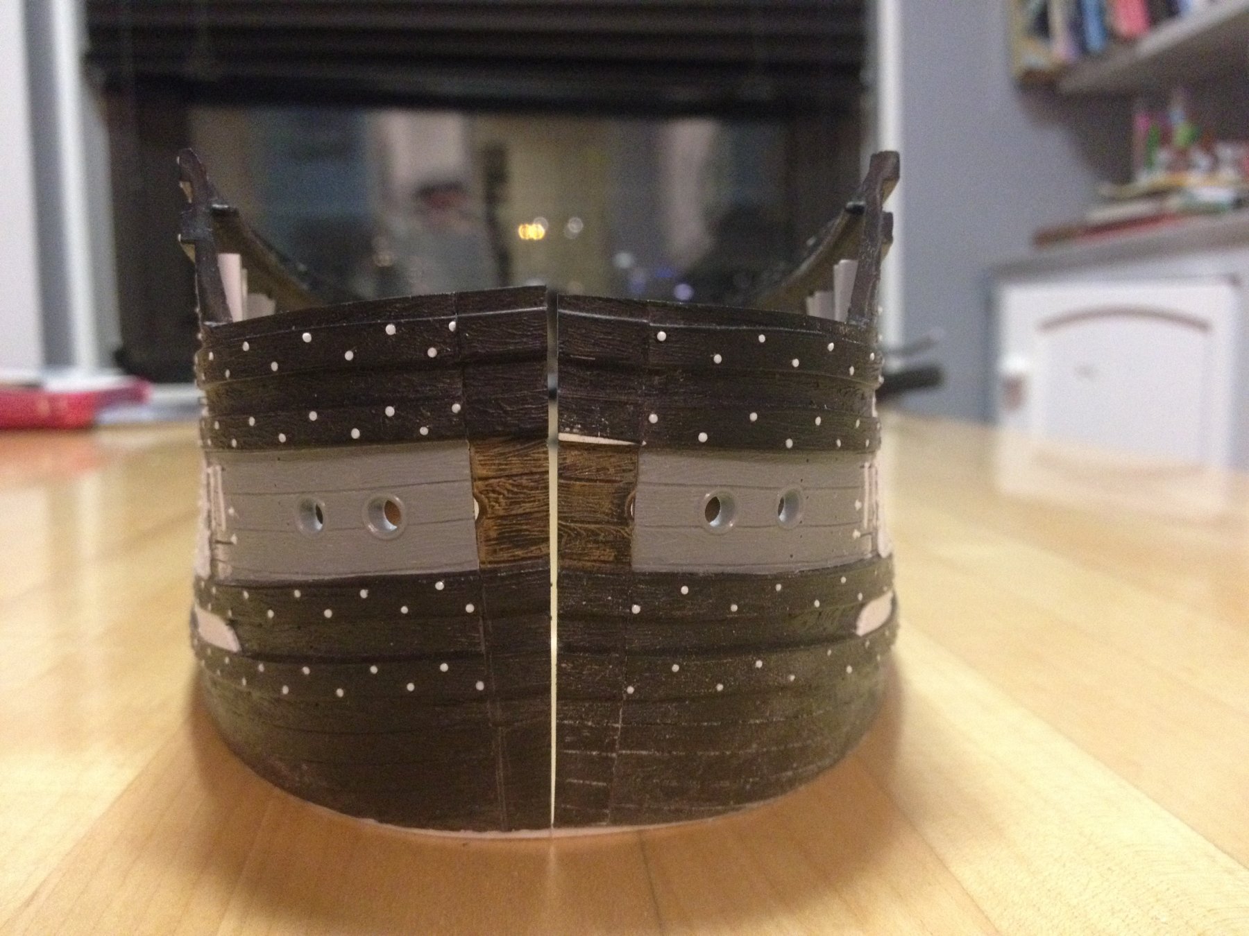
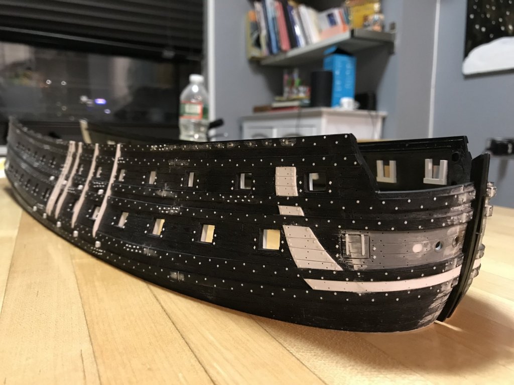
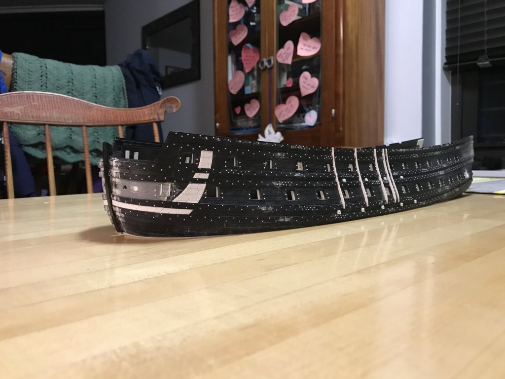
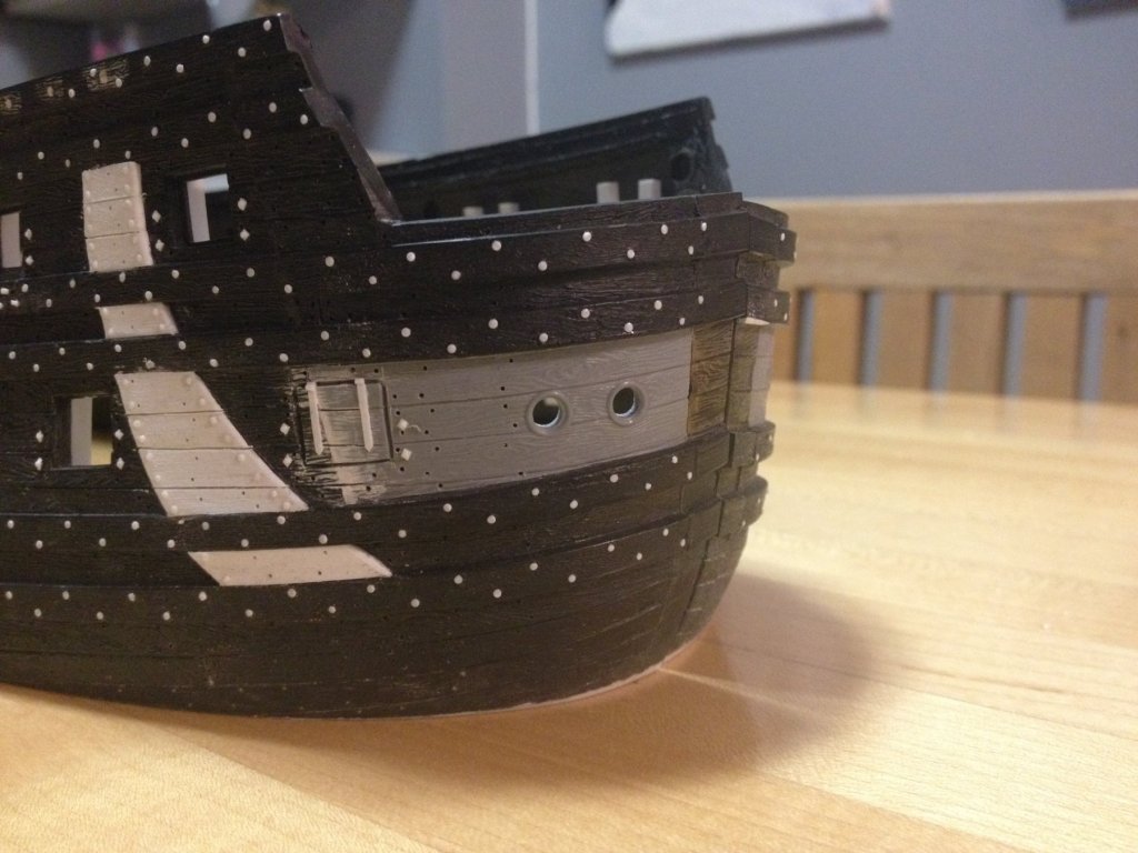
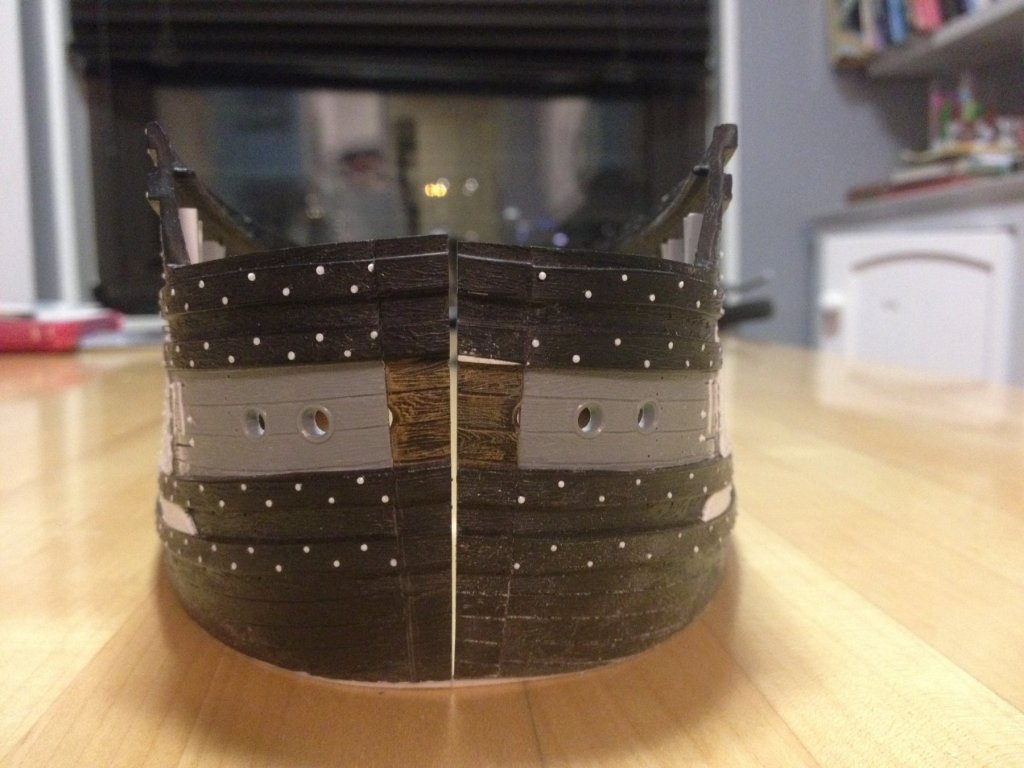
I’ve finished reconstructing the bow, with the stem pieces glued back in place. I’ve added in the through-bolts, the nail impressions and any other bits that had been broken off, in the process. The first batch of through-bolts I made was too small in diameter and noticeably didn’t match the others surrounding them. So, I scraped those away and replaced them. I found it was necessary to insert another shim under the port side, in order to bring the wales and plank lines up, and fully in alignment with the starboard side. After I had cut away the lower hull, I was using a long sanding block to true up the water line. I was not yet aware, however, how quickly un-even pressure can remove plastic in areas where you don’t want to; consequently, I oversanded the port bow by a full 1/16”. Nothing in life is perfect, but this added shim - together with judicious additions and subtractions to the wales - are a reasonable facsimile of symmetry. With a nod to Marc Yeu, aka NekO, I also filled between the lower main wales, as a forward continuation of the anchor lining. He was quite right to point this out, and I am happier now that I have included the detail. I was uncertain as to whether I should simply nail or through-bolt the length of this thicker planking, to match the wales it is sandwiched between. I decided upon nails, as I had the rest of the anchor lining - only through-bolting the edges of the lining. I don’t know whether this is actually correct, but this is an approach I have seen on a number of really excellent models. I like the way it looks, and couldn’t find any evidence (not just pictures, but written descriptions of known practice) in my “archives” to directly refute it, so I went with it. The added benefit of adding this strip is that it crosses and helps strengthen the extension joint. For the time being, I have not trued-up the mating faces of the stem. I will wait to do so until I am actually ready to assemble the hull halves onto their base plate. Not surprisingly, it was again necessary to apply direct heat from a tea light candle to the port stem piece, in order to bring it back in line with the modified run of the port hull extension pieces. The interior surface got a little melty, but a few applications of heat brought the two pieces into agreement. The outboard-most hawse hole was filled with styrene rod, faired and any remaining discrepancies were smoothed over with Squadron white. Drilling the new in-board hawse hole was done in stages with three bits, graduated in size. I was a little apprehensive about doing this because the 3/8”, on center, spacing lands the hawse hole directly on the bow extension joint. Further complicating matters is the fact that the holes aren’t drilled perpendicular to the outer surface of the hull, but at an oblique angle. My solution to this was to sloooowly start the hole - with a very light touch on the drill trigger - with a 1/16” bit. Once the bit was about a 1/16” into the plastic, I adjusted the angle of the bit and finished drilling through the hull. The rest was easy. I followed with a 6/64” bit, and finished the hole at 1/8”. Again, the symmetry from port to starboard isn’t absolutely perfect (port, inboard hole is a touch higher than starboard), but it is close enough that I can live with it. Although I will eventually be adding cheeks/bolsters to the lower half of the hawse holes, I did want to add back the moulded lip of the hawse hole. After scavenging around my apartment, I found some electronics wire-ties that were the perfect gauge for recreating this moulding. After stripping the plastic from the wire, I straightened the wire and then made three tight wraps around a 5/16” drill bit shank. I lucked out, in that the wire had surprisingly decent tensile strength for such light-gauge stuff, and it held a nice tight coil. Next, I used a single-edge carpet razor, and a light peening hammer to strike through the three loops of the coil, simultaneously, and at a slight angle to the cut. This resulted in at least two open rings that could be teased back, and closed into a nice circular shape. Before gluing them in place, I flattened the backs on the fine side of an emmory board, and was again surprised that the rings held their shape, despite the rough back and forth action. I am very pleased with the result, and only the top half of the rings will be visible above the bolsters, anyway. Here are a couple of shots showing the run of the bow, from overhead, as well as all of the interior bracing: And one final shot of the port side, showing the full aspect of all of these modifications to the lower hull: At the moment, I am debating whether to thin the bulwarks and scribe in plank lines, where the beakhead bulkhead joins the ship sides. The kit’s stock arrangement is to glue the bulkhead plate over the edges of the upper hull/bulwarks. This is not, however, what would have been done, in reality. This detail is more visible at the stern, which is why I did so there, but much less visible at the bow. As I’m re-building all of the decks from scratch, including this detail won’t affect anything important. I will probably go ahead and do this because it doesn’t take long, and not doing so will forever-after annoy me.


- 2,699 replies
-
- 6
-

-
- heller
- soleil royal
- (and 9 more)
-
I’m glad to see you went this route, with the through bolts and carriage bolts, EJ. They are nice details that add so much to the finished model.
-
This should be a good one - I'm in!
-
It may very well make sense to do that, Dan, and I have an extra set of headrails (courtesy of Henry) with which to experiment. Splicing in short segments may also be a possibility. As for whether it makes sense to do any of that, I suppose it all depends upon how much stretch, or how long a splice is needed. Anyway, there is time yet to ponder that.
- 2,699 replies
-
- 2
-
-
- heller
- soleil royal
- (and 9 more)
-
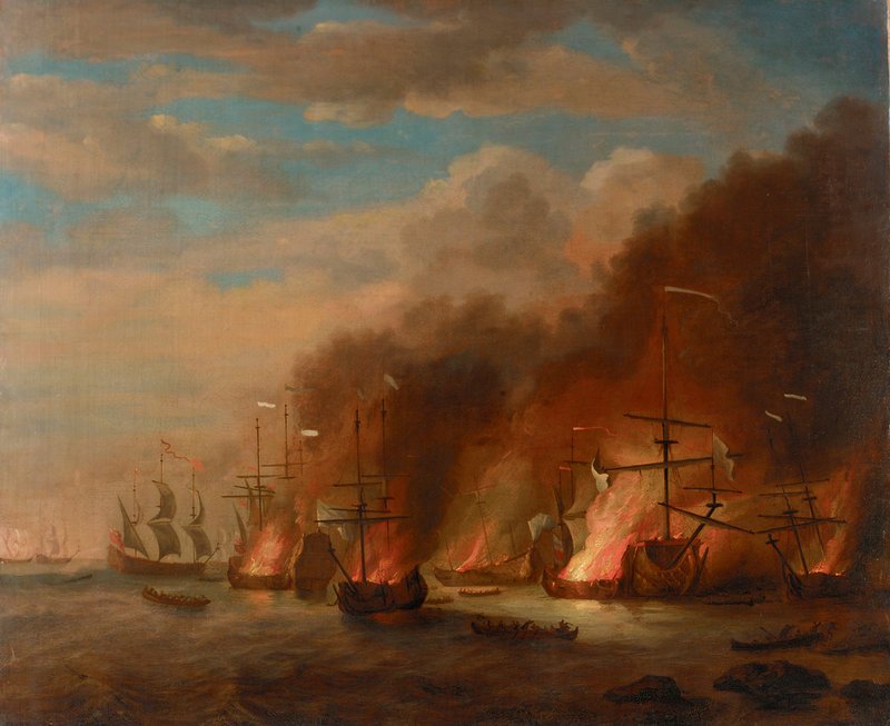
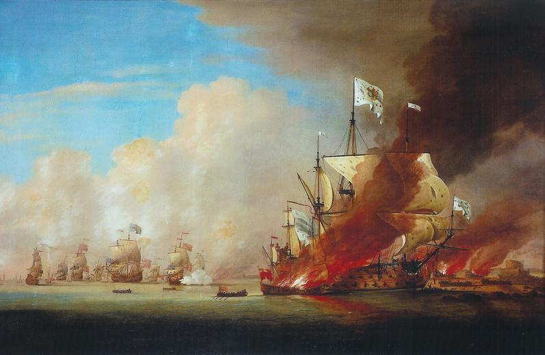
My hunch has to do with the way that Peter Monamy has represented the headrails in this painting: It's subtle, but I believe this shows a more arcing plane of the three headrails, as one is accustomed to seeing in English and Dutch practice. There is another painting of the Destruction of SR, attributed to the VDV studio, that shows only the bow of the ship. The composition is a cloud of smoke and turbulent flame, without much detail, but the headrails also appear sloped, in this work. As with so many things - I could be completely wrong, but it's worth investigating further.
- 2,699 replies
-
- 3
-
-
- heller
- soleil royal
- (and 9 more)
-
I think that you are correct, Henry, and I've already half convinced myself to remake the headrails anyway. In part, because while Heller (and Tanneron) model the headrails as three rails in the same vertical plane, I believe that they should more correctly follow the downward arcing plane of the supporting knees. I haven't done any hard research on this. For now, it is just a hunch.
- 2,699 replies
-
- 2
-
-
- heller
- soleil royal
- (and 9 more)
-
Thank you Jim, Dan and EJ, and everyone for the likes and looking in. Yes, EJ, it was a little touch and go for a while, there. But this is just one of several challenges that my approach to the model will present for me. One thing that will be interesting to see is whether widening the bow effectively shortens the head rails so that the scrolled volute - tucked just behind and above the wings of the figurehead angel - drop below the level of the sprit mast. In the stock arrangement, the scrolls flank the sprit mast and spoil the fairlead of the bowsprit running rigging. I may not be able to avoid re-making the headrails, though, because if they drop too far there will be no reasonable room for the knees that are supposed to support them. Custom headrails would incorporate a somewhat flatter arc, which would be more flattering, anyway. If I go this route, I could still recycle the ornamental aspects of the stock headrails, thus saving considerable time and effort. I thought that Michel Saunier created a very good shape for his headrails, and I would likely attempt something along those lines.
- 2,699 replies
-
- 2
-
-
- heller
- soleil royal
- (and 9 more)
-
That is an excellent suggestion BW, and one that I considered. Unfortunately, though, it wouldn't have worked because of the curvature of the hull;. The aft end of the hawser insert would have stepped inboard from the outer plane of the hull, if that makes sense. But I liked the idea for exactly the reason you mentioned. Thank you, BW, for following along and weighing in.
- 2,699 replies
-
- 2
-
-
- heller
- soleil royal
- (and 9 more)
-
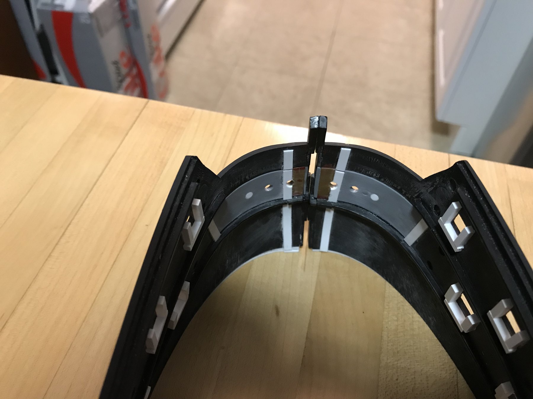
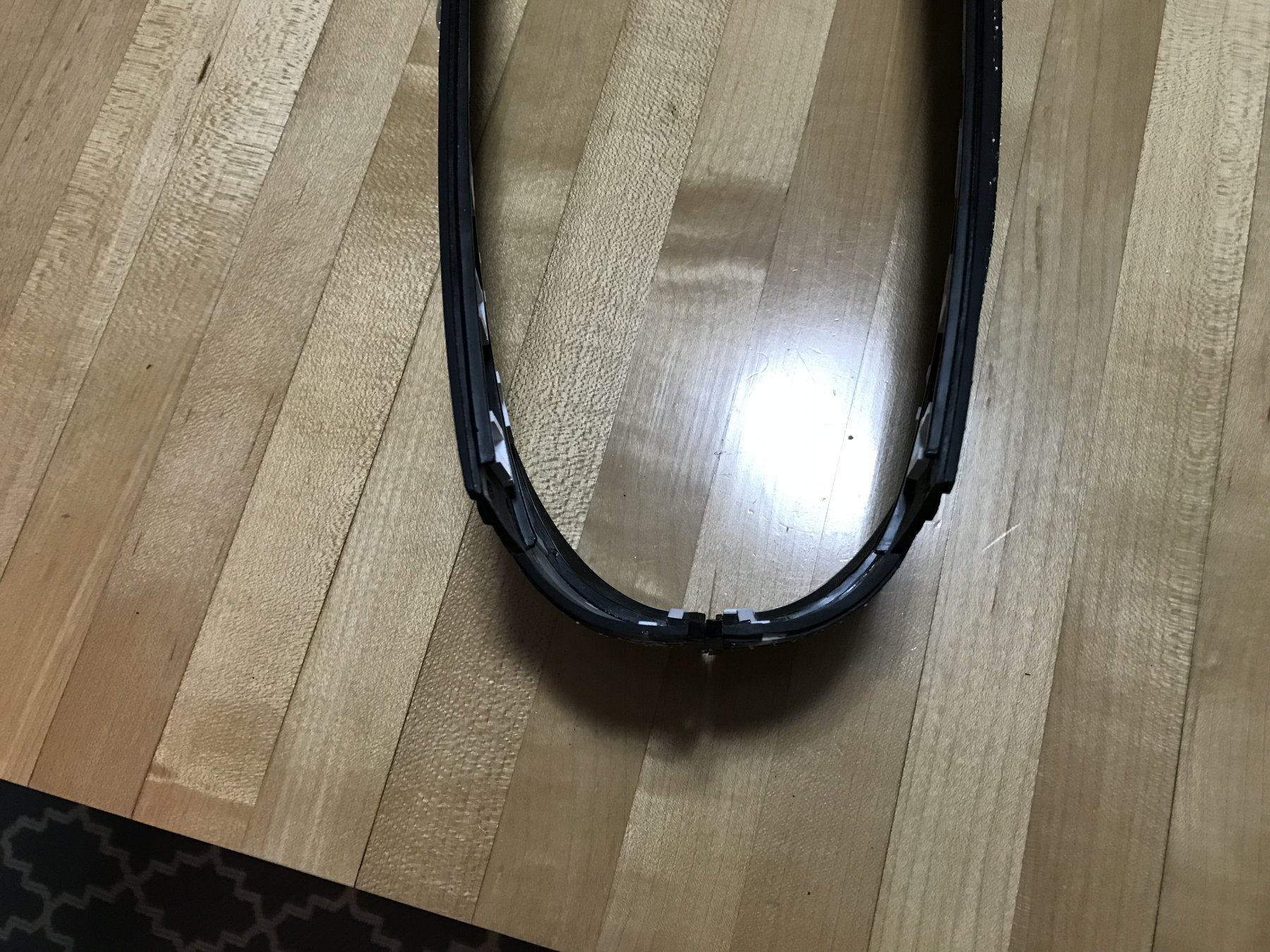
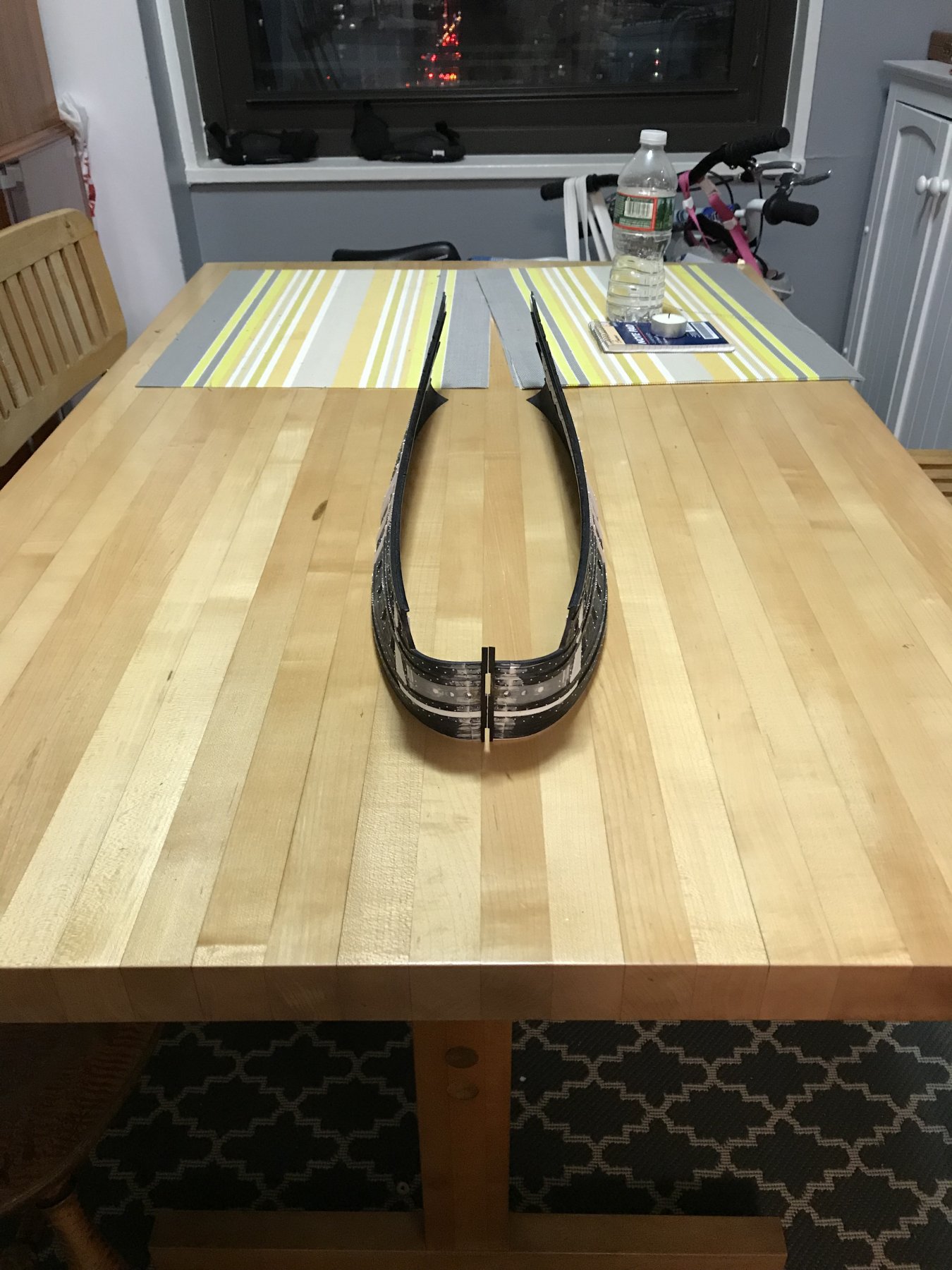
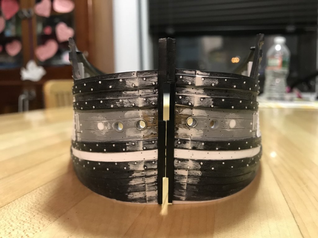
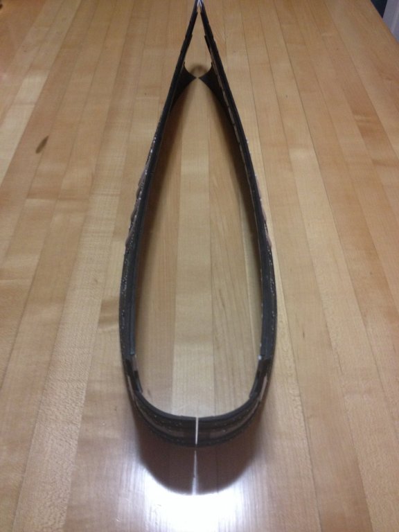
I just wanted to post a few pics with the bow now in alignment. After plumbing the stem, it became apparent to me that the angle at which the stem pieces will rejoin the hull is too acute, causing the hull halves to pinch inboard, towards the centerline. I could have re-glued the stem pieces, as is, and there probably would have been enough flex to spread the stern to the necessary width, but this inevitably would have created distortions in the hull, along it's length. So, I corrected the angle at the stem, and now the bow closes neatly, while leaving the stern open at a workable width. I thought I had taken a pic of this, but alas, I did not. Lastly, here's a shot of the revised bow from straight away. You can see that I shimmed up the port side. I'll still need to do a little addition and subtraction of the wales to reconcile one side to the other. There is a crack of daylight at the joint, which disappears when placed on the kitchen countertop. A straightedge in two directions on both the countertop and table tell me that both surfaces are flat. Nonetheless, this discrepancy appears on the table. Go figure! However, because it closes neatly with light finger pressure, I have decided to leave well-enough alone, and not chase "perfection." I've re-enforced the back side of the joint. It occurs to me that the sliver of hawse hole that came in with the extension pieces is a good and reasonable re-location for the missing hawse hole. I'll simply fill in the outboard-most hole with styrene rod and putty. The rest is just putty, re-scribing lines and detailing.

- 2,699 replies
-
- 10
-
-
- heller
- soleil royal
- (and 9 more)
-
Well done, Dan! The fidelity from your model to the real thing is impeccable. It all looks just right.
- 287 replies
-
- 3
-
-
- michelangelo
- ocean liner
- (and 1 more)
-
Thanks Vic. This is a relief on many levels; relief that it wasn't a catastrophic failure; relief that it solved the problem, so that it doesn't appear there was a problem to begin with; relief that I can tidy up this end and move on with the project. It always would have gnawed at me, if I were forced to gerry-rig some less than ideal "fix" because I should have been paying more attention, in the first place. I always work later in the evening, after the kids go to bed, so I guess I got a little cocky and lazy.
- 2,699 replies
-
- 2
-
-
- heller
- soleil royal
- (and 9 more)
-
My initial experiments with a tea light worked quite successfully. On my scrap pieces, I found that I could gently waft the flame within an inch of the inside surface - just until the surface of the plastic looked like a freshly baked brownie, smoking ever so slightly - and then I could push the plastic gently and hold for 10 seconds until it set. The results were reversable, and repeatable on the same sample piece. The surface detail was not distorted. I think the relatively thick plastic was my ally in this adventure. So... I put on my big-boy diapers and took a sip of Jamesons... and then, I held an open flame to the inside of my model The first adjustment got me about half the way. The second heating brought me almost home, but seemed to soften and shift the glue joint. The joint solidified, though, so I figured this was actually an exercise in strengthening. The final adjustment nudged the flattened areas into a more rounded shape and the joint, itself, back into alignment. All the while, I was checking against the starboard side for symmetry. I re-sanded the bottom edge for the shims, sanded the inside faces of the extension joints for re-enforcing strips of styrene, and Bob's your Uncle - so to speak. Pics to follow. Diaper to be exchanged for clean skivvies. I'm now in the cabernet sauvignon segue of the night. Watching a little basketball. All is well.
- 2,699 replies
-
- 5
-
-
- heller
- soleil royal
- (and 9 more)
-
That ultra-marine looks right on to me, EJ! Fantastic progress. Bolting the wales will be well worth the effort, so I encourage you to go for it. Mr. John Jameson has been my reliable right-hand-man, lately, so go ahead and partner-up!
-
Definitely slooooow is the order of the day. Thanks for weighing in, Yankovich!
- 2,699 replies
-
- 2
-
-
- heller
- soleil royal
- (and 9 more)
-
Interesting idea with the kerf slots, Dan. I will take that idea to the laboratory. I have a carving veiner that should make that easy to do.
- 2,699 replies
-
- 3
-
-
- heller
- soleil royal
- (and 9 more)
-
I agree, Jim, that a heat gun is a good option. Unfortunately, I do not own one. I may, however, be able to borrow one. Tonight, I will experiment with open flame. I have four chances - utilizing the discarded bow section, immediately below the waterline - to see what flame does to an area with similar curvature. I will need to cut away the stem on these extra pieces, but that's a small sacrifice of labor for science. If I just can't control the heat of a flame, I will look into a heat gun. Thank you, for weighing in.
- 2,699 replies
-
- 2
-
-
- heller
- soleil royal
- (and 9 more)
-
Okay, so I could really use a little advice, here. Last night, I plumbed the hull halves at the stem joint. In doing so, I realised that I will have to mimic the same shimming on the port side that I did on the starboard side, below the bow. As I had hoped, plumbing the stem joint did make a positive reduction of my overlap problem. I'm sorry that I have no new pictures at this time (phone capacity maxed out, at the moment), but the current overlap is a heavy 1/16". Before I shim the lower edge on the port bow, it occurs to me that the highest risk/reward solution to his problem is to apply focused heat to the overlapping plastic and simply nudge it into correct position. Fortunately, I have loads of plastic to practice on; Henry's hull, and my own lower hull halves. Unfortunately, I have precious little experience applying heat to styrene for this purpose. I think that a hair dryer is too diffuse a heat source and might warp a broader area and probably weaken the glue joint. A sand heat sink might be a good solution, but it's difficult to guage what temperature to heat the sand and for how long to let the roughly 1/8" plastic sit in the sand; this technique would require quite a bit of experimentation to get a sense for it. My inclination is to use a low flame, like a tea light, so that one hand could hold the piece, while the other could be in constant contact with the problem area, so as to gauge the exact point where the plastic becomes malleable, but before it melts into garbage. It seems to me that the trick is to determine the correct distance between the plastic and the flame. Does anyone have any experience and advice in this realm? Is this just a terrible idea? I could sand back and re-shape this area, but I would prefer not to, if I can avoid it.
- 2,699 replies
-
- 3
-
-
- heller
- soleil royal
- (and 9 more)