Hubac's Historian
-
Posts
3,314 -
Joined
-
Last visited
Content Type
Profiles
Forums
Gallery
Events
Everything posted by Hubac's Historian
-
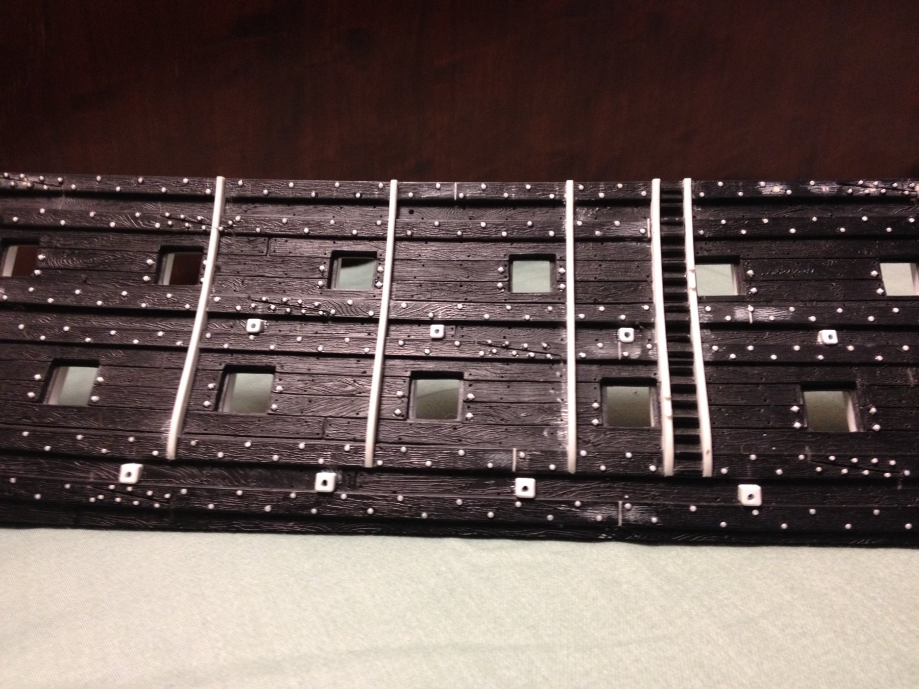
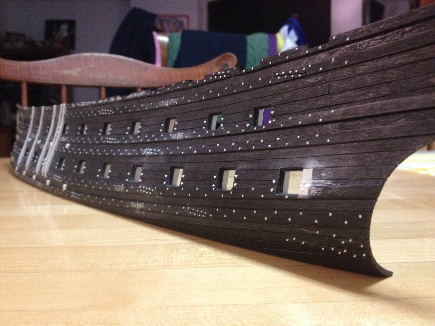
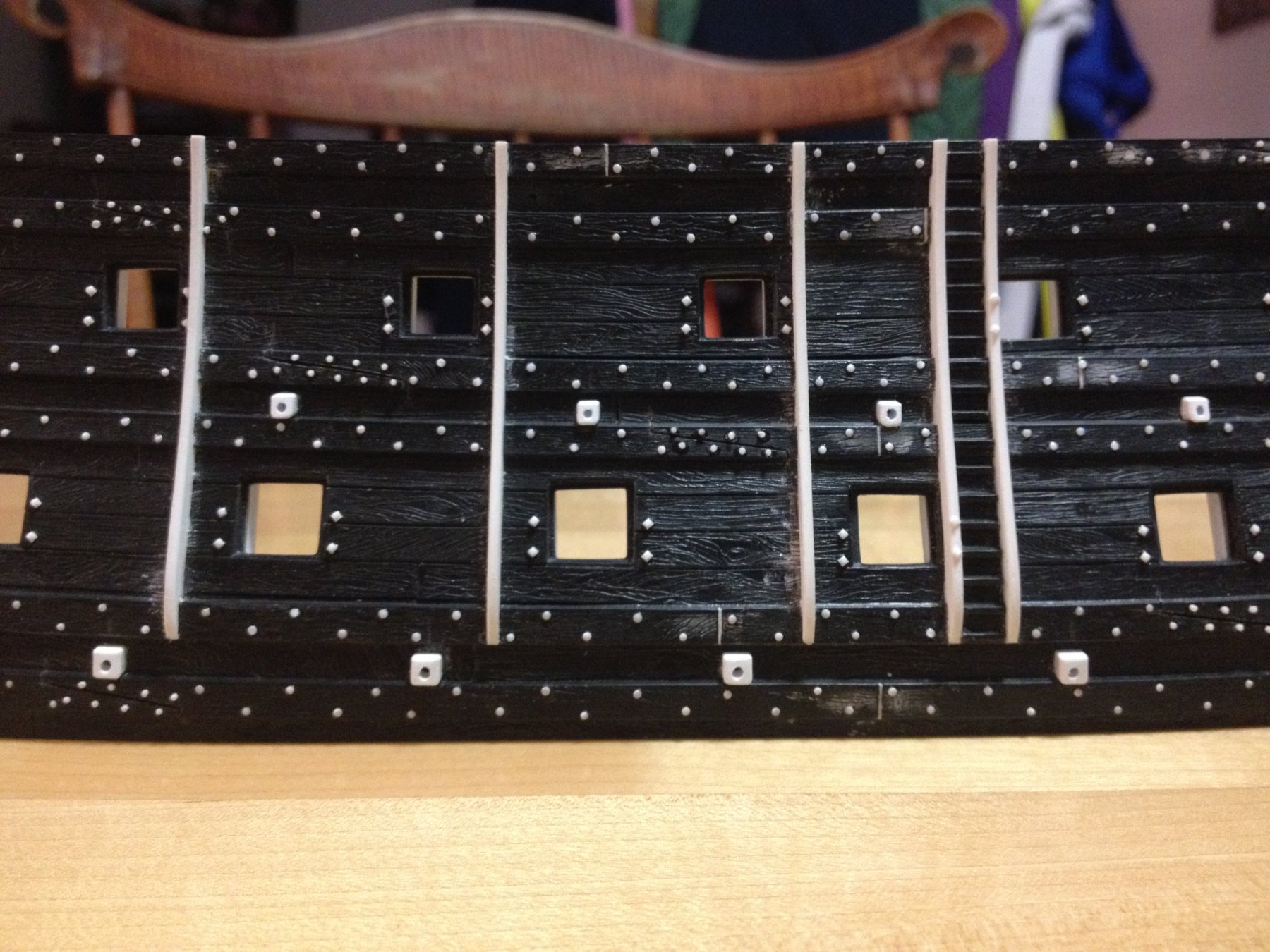
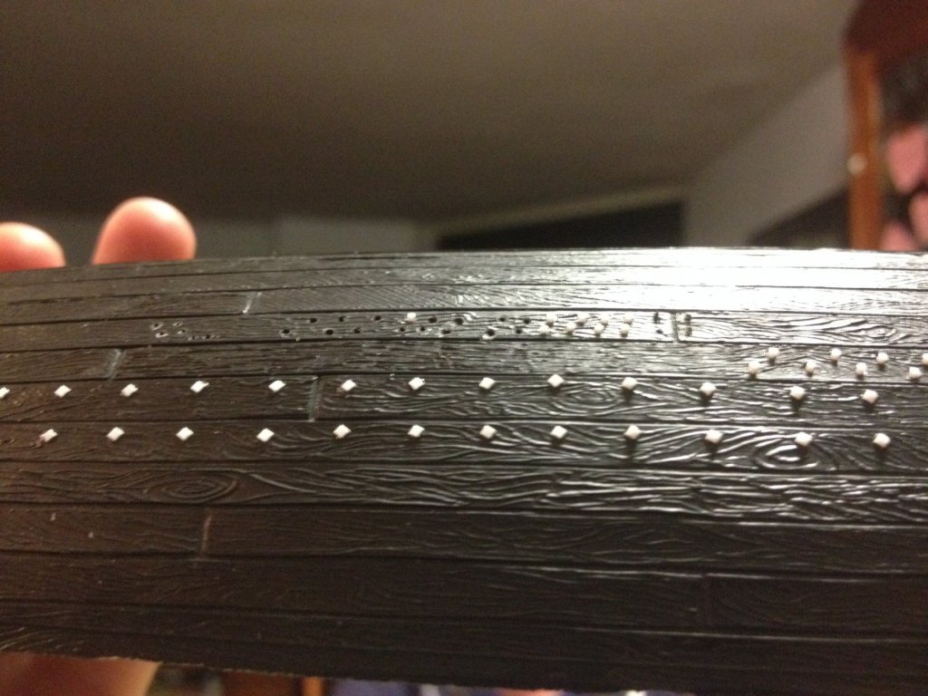
 I have been busily mapping out and drilling nail impressions in the deadworks. I haven't put a caliper to the bit I'm using, but suffice it to say that it is near impossibly small. There was some trial and error to arrive at a bit that left a plausible impression, and that didn't overheat and clog with melted plastic too quickly. I still have to stop the Dremel and clear the bit every 15 holes, or so, but that's much better than the 5-8 range. As a quide to my spacing, I am using the exposed timber heads of the caprail. This works out to about 5/16", on center for the most part, but there are several instances where I'll have to run a row or two at 1/4" spacing, in order to maintain overall consistency. In the waist, and for about six ports aft of the waist ladder, the nailing pattern runs perpendicular to the waterline. With the hull half sitting on the table, I simply use a try square to align my blue painter's tape guide for keeping my lines nice and straight. As the sheer rises, further aft, it has become necessary to skew my tape guides ever so slightly, by eye, so that my nailing pattern doesn't run too far askew of the gunport framing, with which it should remain parallel. After much deliberation, I have decided to mimic the alternating nailing pattern that Dan Pariser used for his very thoroughly researched and excellent Queen Anne's Revenge. I have known Dan for a long time now, and there is nothing he does without considerable thought and research. Here are a few pics of my progress, so far. They are hard to make out in the black plastic, and after priming and painting they should just barely show as faint impressions.
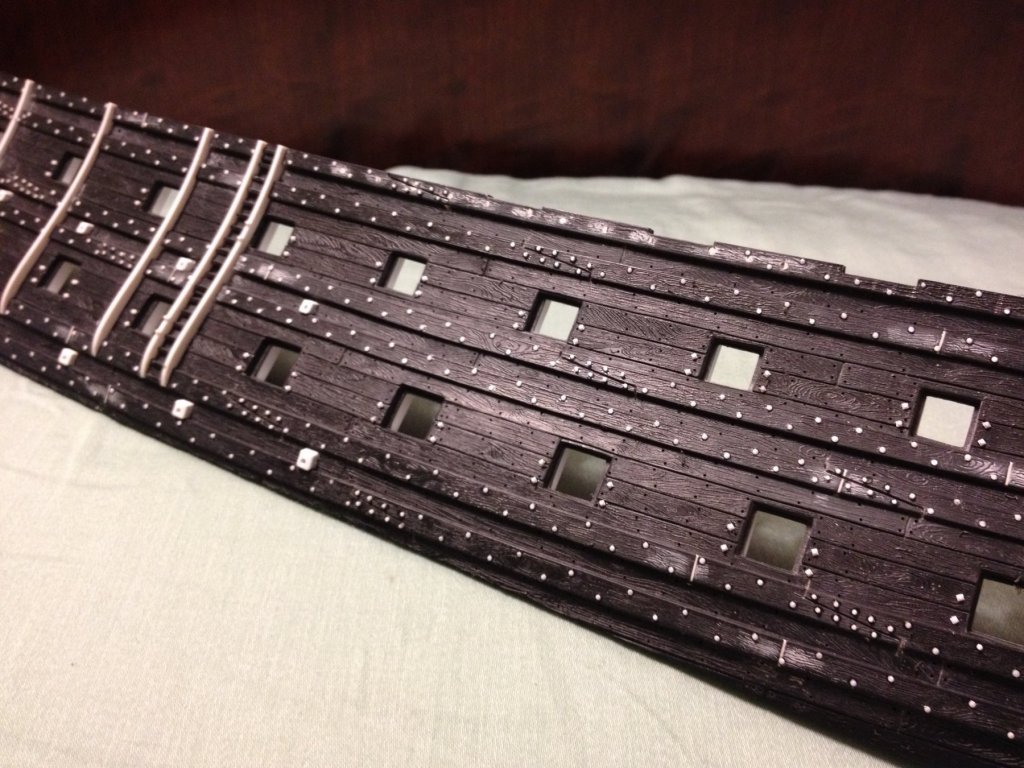

- 2,699 replies
-
- 10
-

-
- heller
- soleil royal
- (and 9 more)
-
I'm curious as to whether you are using some form of epoxy as your adhesive; West System, maybe?
-
Wow! This is right up my alley. I'm in! Beautiful hull form, exceptional woodwork, and hands-down the best photographed build-log I have seen so far. I'm really looking forward to watching this one take shape. Great work, so far.
-
Excellent work, Gaetan, in straightening her out! She's a lovely ship rounding into form. I'm really enjoying your informative build.
-
Thanks Daniel! As far as Soleil is concerned, the shame of it is that they do an incredible job of copying the ornamental details from one of the existing original cannons, but as I say, they do not capture the appropriate sense of girth that is so evident in every Van de Velde portrait ever drawn. For carriage and rig updates to the guns, I am looking very closely at Popeye2Sea's excellent build log. His carriages look amazing. I'll have to look at those links for photo etch; thank you for the info.
-
Hi Daniel, One question about the guns:. The scale of the barrels looks really good. While I have this kit, it's siting in a basement in PA and I can't readily look at it. Are these the stock cannons, or did you make/buy something closer to scale? One of my issues with Heller's Soleil Royal is that the muzzle/barrel width, and bore diameter are too narrow and spindly looking. I will have to do something about this, and am searching for a way to perhaps recycle the kit's stock barrels by, perhaps, dipping them several times in some sort of resin, in order to increase their breadth. I could then drill out the appropriate bore diameters. I am wondering your thoughts on this subject. thanks, Marc
-
Okay Daniel, I'm only on page 3 of your build log - and I'm going to stop hitting the like button, so that you are inot completely innundated with notifications, but... I am completely BLOWN AWAY by your attention to detail and your willingness to re-work the smallest details until they are RIGHT. My German half is crying meticulous tears of joy! Gonna keep reading
-
Well, that is just about the only case of "herpes" I would welcome in my life ; pretty to look at, and no painful rash! Well done, Michel!
-
I hopscotched through another member's (who had visited my build) history log and found your highly intriguing build of the Heller Victory. I so like the excellent modifications and scratch-work on this main top, that I'm going to go back and read through your whole log. It seems that much of what you are doing might be really helpful to me, even if we are building in different centuries. So nice to see such excellent, clean work. I'm looking forward to catching up!
-
Thank you very much, Cedric! I believe it is now possible to see the hidden potential in the Heller kit, in order to make it a better model than it already is. So I will keep plugging away. I'm very excited to see your progress, Cedric!
- 2,699 replies
-
- 2
-
-
- heller
- soleil royal
- (and 9 more)
-
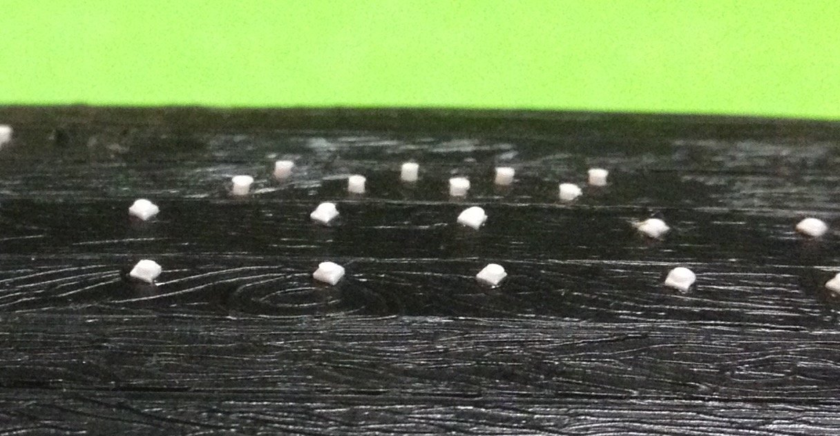
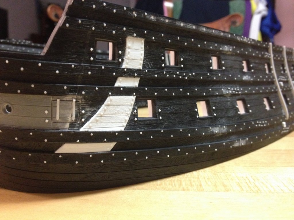
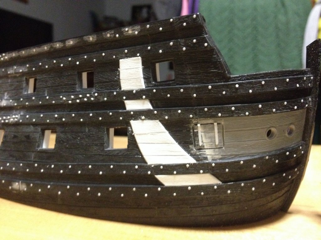
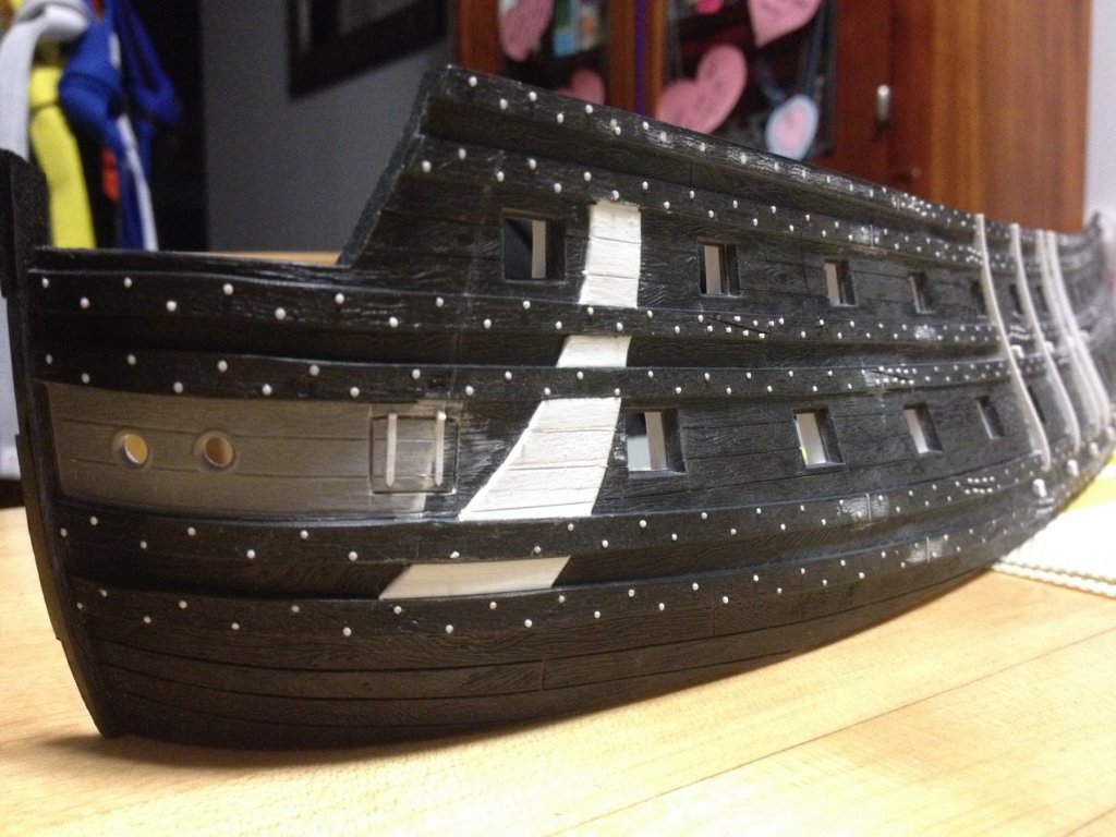
Tonight, I finished up the gun carriage tackle through-bolts. The following series of pictures attempt to show the impact of adding this detail. Only the second picture manages to capture the bolt within the washer, such are their size. I'm not sure whether it is a correct detail, but I also decided to bolt the edges of the anchor lining. Although, I now realize that the linings would have simply been a double thickness plank trimmed to the shape of the lining, I decided to bolt the "edges" anyway. Next, I will experiment with some sort of shallow nailing pattern for the rest of the planking. I think if I chuck the tiniest drill bit I own into a pin vise, and simply make a few turns into the plastic, such that the bit's point just makes an impression, that that might be enough to show some kind of fastening pattern. The linings will be "nailed" between edge bolts. P.S. I'm not sure why the above text is underline formatted, because I did not do that deliberately, and underline in the toolbar is not highlighted, when you select text in that block. I can't seem to correct it, so there it is. If you look closely, you'll see that I even placed carriage tackle bolts on the skids that frame the ladder, because the skid frames took up all available space, immediately next to the affected ports. I'm not sure whether that is a correct detail, either, but it seemed like the sort of accommodation a builder would make under the circumstances. I'm approaching the end of my lower hull modifications. Those are a lot of tiny bits of plastic! After the "nailing," I'll do the bow and stern extensions, re-locate the hawse-holes, and then I will probably focus on making the alterations and additions to the upper bulwarks. After that, I will have to figure out my drawing problem.


- 2,699 replies
-
- 8
-
-
- heller
- soleil royal
- (and 9 more)
-
I'm glad to see you back in your shipyard Doris. I think your modifications are good, and I'm looking forward to your updates. Regards, Marc
- 1,035 replies
-
- 5
-
-
- royal katherine
- ship of the line
- (and 1 more)
-
Okay, then what about this: Mask your line, top and bottom as perfectly as your eye enables you to do - having cut sufficiently long strips of masking tape to make nearly one complete run, stem to stern. The complicating curves at the bow and stern need to be dealt with in shorter lengths. You will have first ripped your tape into no more than 1/8" strips, this will enable you to easily stretch and adjust your tape to move as needed, with the sheer, etc. Once you have the line masked the way you want it, thoroughly burnish the tape with a straight piece of stiff card. Then mask as near to the line with a wider swath of masking tape. Then mask off everything else above and below the line with paper. Here's the critical step:. Spray the, as yet, uncolored line with a clearcoat that matches the desired sheen of the rest of the model. Once that's dry, airbrush in your color wih a few light coats. If, after removing your masking, you see any areas where the clearcoat has blead under the tape - simply mask off your line in the affected areas, level the clear coat, and when the time is right in your process - spray the whole .thing one last time with that matching clear coat. Failing all that, pour me a glass of bourbon on a slow evenning, and I'll tape off your lines to perfection.
- 287 replies
-
- 3
-
-
- michelangelo
- ocean liner
- (and 1 more)
-
Dan, why is it that you won't mask and airbrush the green striping?
- 287 replies
-
- 4
-
-
- michelangelo
- ocean liner
- (and 1 more)
-
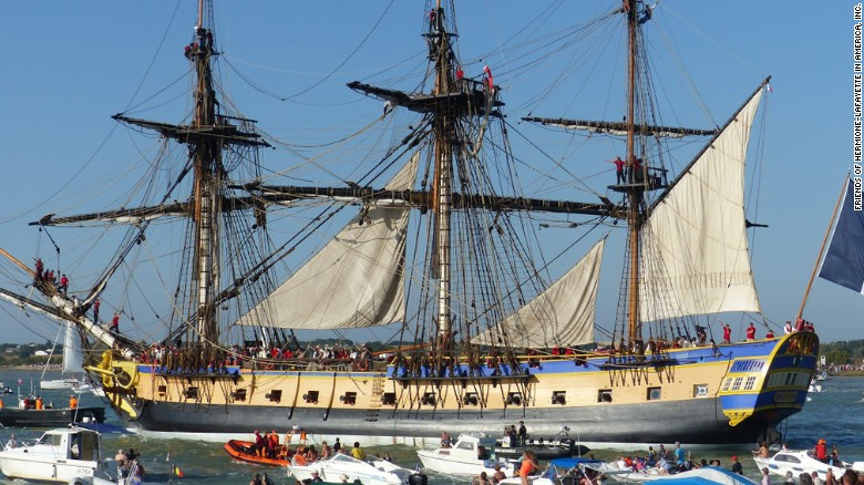
The funny thing is that I just sent Marc a PM, discussing this paint issue, among other subjects. But, I had not yet read his last entry into my build log. For the sake of the public conversation, I will copy and paste the relevant portion of that message - the irony can't be beat! ~~~ it seems that a number of well-known French models make use of the color (ventre de biche), as a painted color, on the dead works: Le Fleuron (red, yellow ochre, ventre de biche), Le Temeraire (Tusset model), and Le Ville de Paris are three well-known examples. But then, I was looking at the replica of Hermione, and she too appears to have her deadworks painted in this brownish, yellow color. And then, I looked once again, at a second Peter Monamy painting of the destruction of SR, which focuses on the bow: Here, too, ventre de biche appears to be a deliberate and applied color. What all of this means for me is that I will have to work up a series of paint samples; one that is a lightly weathered, natural wood tone, one that is VDB freshly applied, and one that is VDB lightly washed to show a little sea grime. As this is going to be a diorama model, I just want to avoid an overly painted looking model; sort of the way a girl wants to look as though she isn't really wearing make-up, if that makes sense to you. ~~~ And, by the way, I also agree with Marc that one must first understand what was, or likely was, before taking any divergent paths. The question of combining yellow ochre for much of the moulded work with gold for the important sculptural work would be an artistic decision for me on the basis that those golden ornaments would then stand out better, in relief; they would be more impact-full.
- 2,699 replies
-
- 5
-
-
- heller
- soleil royal
- (and 9 more)
-
Exquisite work on the guns, Marc! I agree with you, also, that Victor really captures the essence of what a sailing man-o-war must have been like, on the water. To me, his ships are perfect miniature recreations. And on launch day, your miniature Tourville will spring to life and take command of his reborn Royal Sun. Well done, my man! Well done!!
- 208 replies
-
- 3
-
-
- le soleil royal
- 104 guns
- (and 2 more)
-
Thank you, Marc! I will tell you that I have been thinking about your suggestion for the anchor lining - that it should fill-in completely between the lower main wales, right up to the stem. After looking through my image database, virtually all French models confirm this detail. I will do so, as well, but only after I add on the bow extensions. The anchor lining will provide the added benefit of making this joint a little stronger. I am also now changing my mind again and leaning towards representing only regular iron nails in the deadworks, but I will have to arrive at a method that suggests a believably subtle pin-prick. Dan's earlier suggestion to draw-in the nails with a mechanical pencil does not work well on this particular model because of the pronounced moulded grain. For the sake of comparison, I will also try to simulate tree-nails with a sharpened syringe needle. What I choose may depend upon which effect reads better visually. In that instance, even if the type of fastenner isn't correct, there has at least been some attempt made to show fastenners in a sensible pattern. I will find a way. Herbert Tomesan suggests very shallow nail holes on his models. The trick is to find a repeatable method that will look good thousands of times.
- 2,699 replies
-
- 3
-
-
- heller
- soleil royal
- (and 9 more)
-
All of this detail gets added on before painting. In fact, I probably won't paint anything until the hull is assembled, the lower transom built and interior gussets and supports for the second gun deck are in place. I want to get all the major handling out of the way before I put finish colors on. I will probably even have built up and installed the quarter galleries, up to the main deck level, before paint.
- 2,699 replies
-
- 2
-
-
- heller
- soleil royal
- (and 9 more)
-
Hey Dan, It is not too late. In fact, I've only done these few tests. I like your idea, and I can see that it would produce fine results. The trouble I see is that, without a drill press set-up into which you could chuck a .033 bit, it will be nearly inpossible to keep the bit on track, and within the narrow confines of the styrene strip - which itself, would have to be double stuck to the table. You could greate some kind of sandwich jig with a measured line of holes, but the bit has to travel, square through the jig material - whatever thickness that needs to be to produce a large number - and still hit the strip dead center. Easier said than done. Then there are process considerations. As best I can see it, your process is a six step process: drill the strip, part the strip into squares, part the rod into approximate lengths, glue the rod through the washer onto the hull, nip close, file to final length. My process is four steps: part the washers, glue the washers, slice the rod to a finished length, glue the rod. At this stage, I've gotten really quick at picking things up with a knife point and placing them. There would be something mechanically satisfying in knowing that the rod actually goes through the washer, but the end-result is the same, I think. On an average night, I should be able to place a near full broadside of washers. Another night to do the bolts. Four nights total, which isn't bad for my timeline. A solid suggestion though, Dan, and yet another example that there are multiple good approaches to do anything.
- 2,699 replies
-
- 3
-
-
- heller
- soleil royal
- (and 9 more)
-
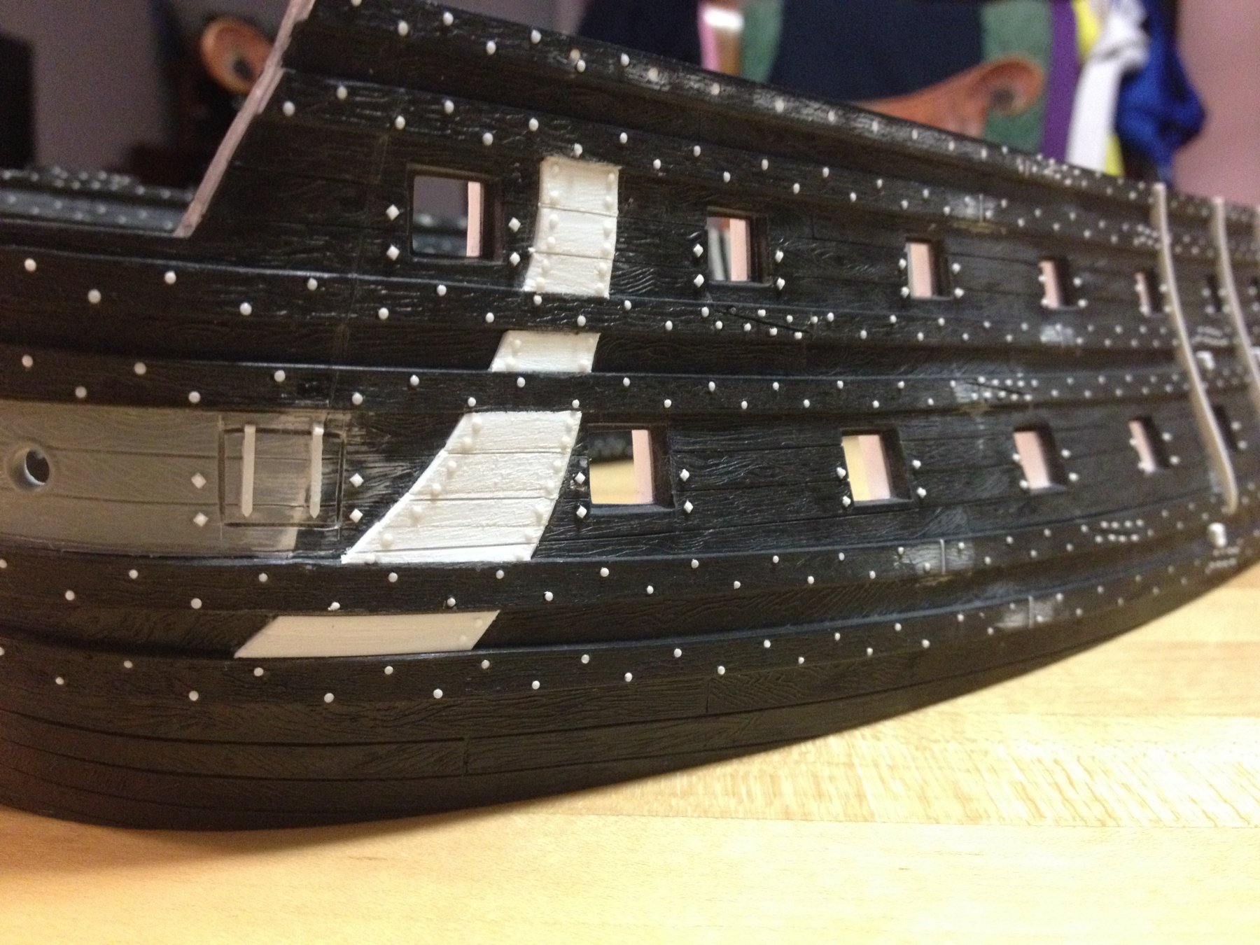
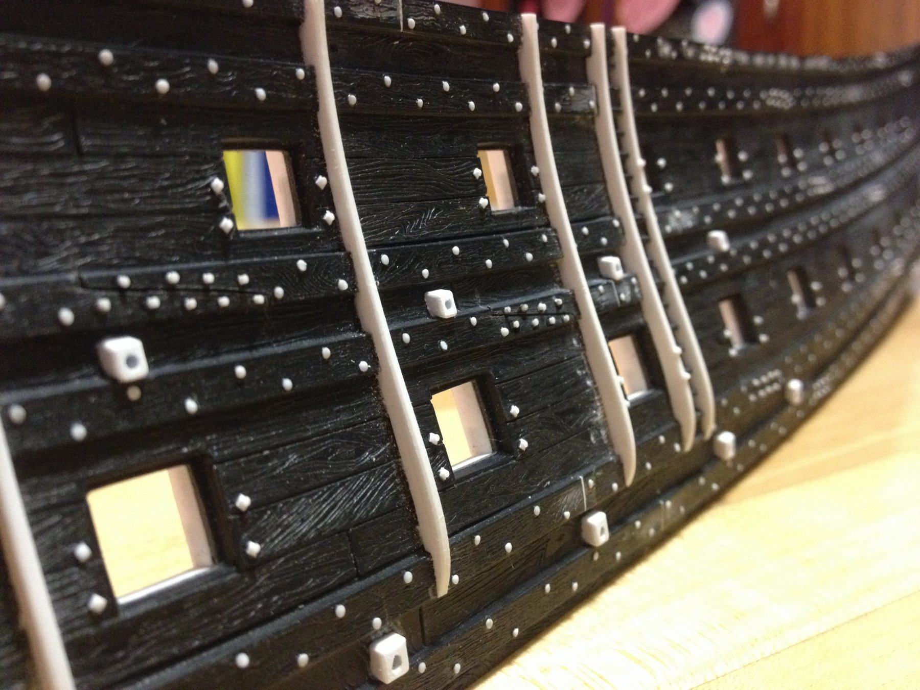
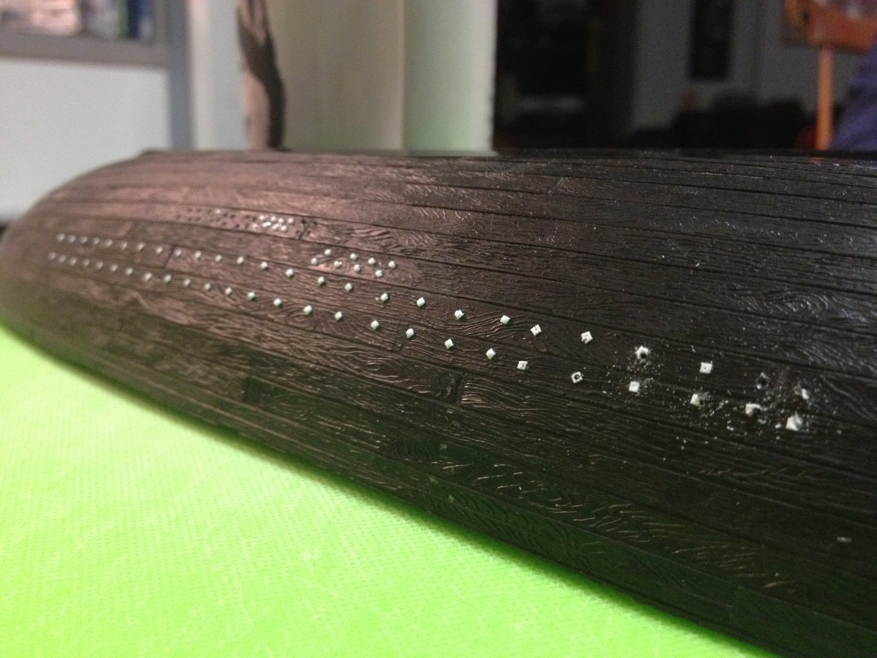
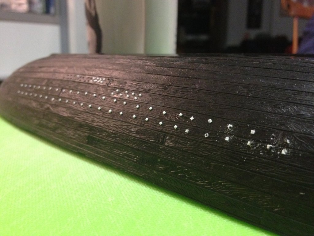
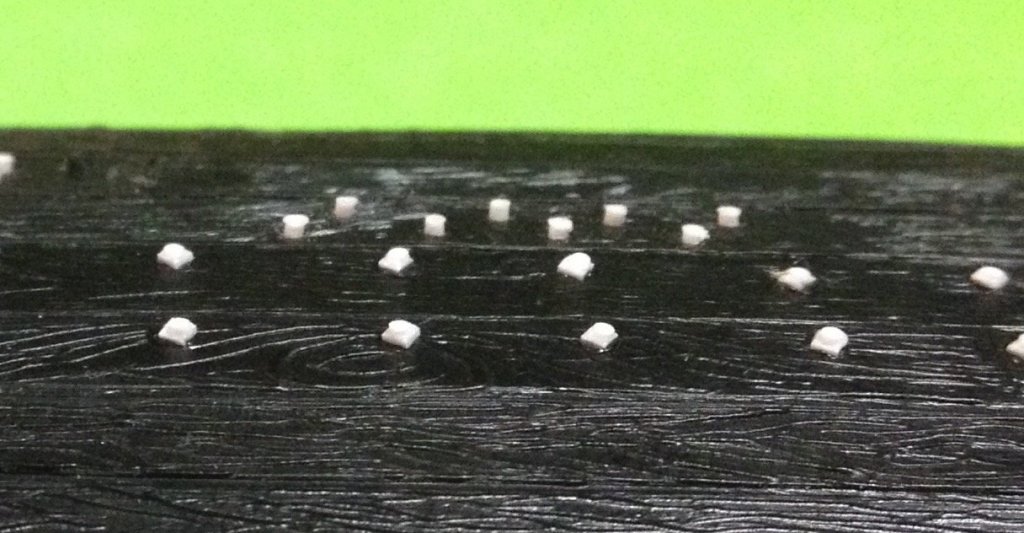
For my next forray into uber tedium, I'll be affixing the through-bolt and washer assemblies - 4 per gun port. The sawed off lower hull is my laboratory for figuring out how best to go about anything, really. I'm using really thin (.011) styrene strip that is .033 wide, which I slice into tiny squares and glue into position with my toothpick and knife application technique. To the right, you can see that I first applied the squares horizontally, as squares: I wasn't satisfied with how they looked because I felt this layout emphasized whatever small inconsistencies there were between squares, in a negative way. So, then I pitched the squares on their diagonal axis, so that they show as diamonds. In this scenario, IMO, these small irregularities read like what you would expect of a hand-forged washer: I was hopeful that I could use the Dremel tool to drill for the styrene rod "bolts," so I pin-pricked the diamond centers to sort of pilot the drill. This didn't work though. The Dremel was too aggressive, and would jump off center and obliterate the washer. Transfering the drill bit to a pin vice was not much better. Finally, I settled on cutting really thin slivers of the styrene rod, which I DID NOT flash with a lighter, and then dropped them on center with a tiny dot of glue. the circle within a diamond is really hard to make out, but this enlargement gives some idea: I think the detail will pop more when they are darkened with paint and maybe dry-brushed with a lighter gray to pick out the circles. I'm thinking that I might experiment with a few flashed bolts to see what that looks like over the washers.
- 2,699 replies
-
- 7
-
-
- heller
- soleil royal
- (and 9 more)
-
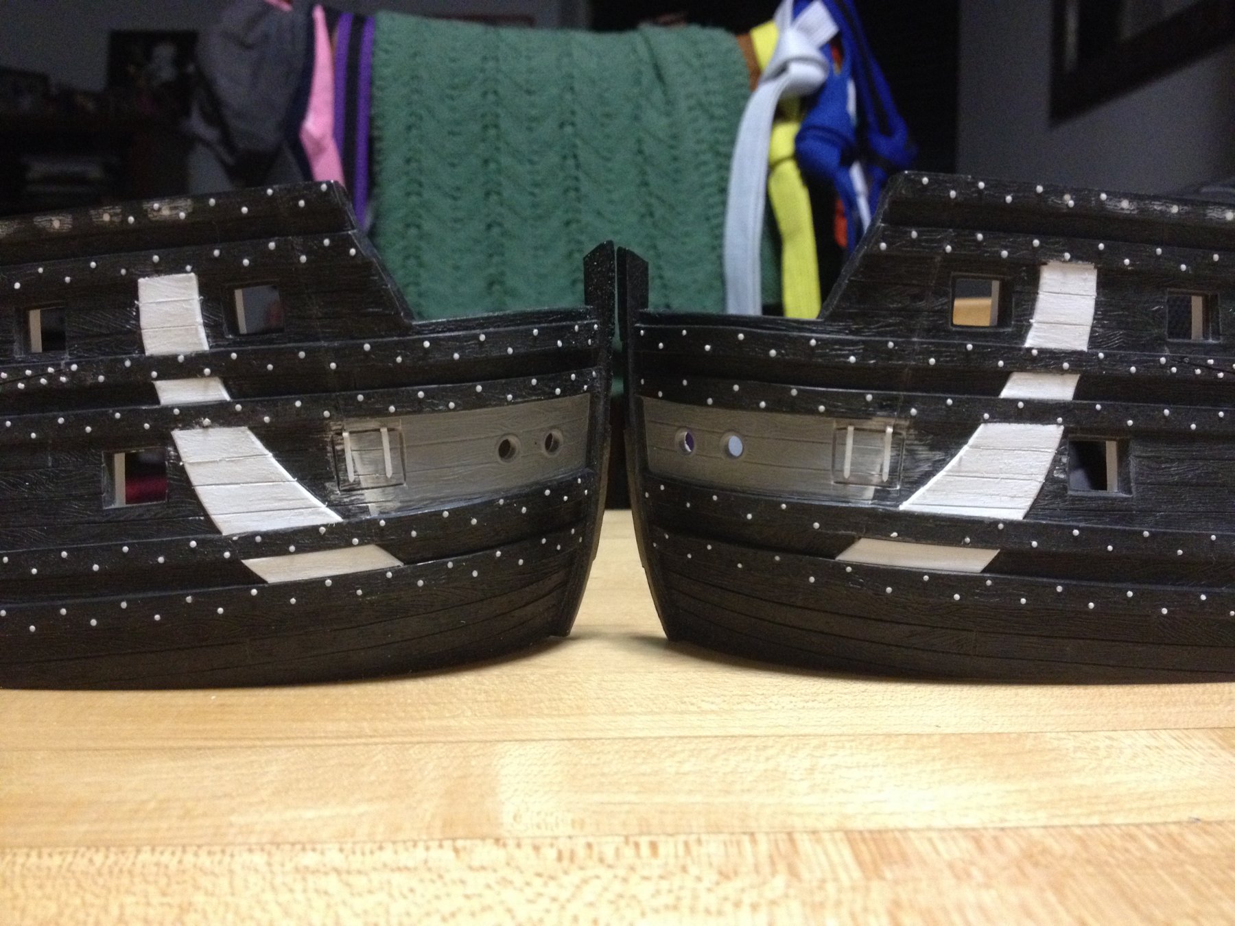
Last night I closed in the last few planks of the anchor lining. I puttied the joints, sanded the surfaces flush and with texture, using 80 grit paper. Then, I scribed back in the plank lines, following the plank lines of the hull. I even scribed in the narrow lines, despite what I said earlier, because the span without those plank lines would appear too broad. This, in my opinion, was worse than the unrealistically narrow plank line being brought to the surface. Lastly, I refined the profile of the lining with a knife and broke the sharp edges with a few scraping passes if the blade. I was experimenting with a sharpened sewing pin chucked into the Dremel, to see if I could make convincing nail impressions. The results were difficult to keep consistent; either too deep, or too shallow, or the pin would develop an accretion of melted plastic, that would subsequently polish the plastic surrounding the pin hole. I will need to continue experimenting, there. Whether it's wholly right or wrong, I am leaning towards represeting a combination of iron and treenail fastenners in the dead works.

- 2,699 replies
-
- 4
-
-
- heller
- soleil royal
- (and 9 more)
-
By the way, the paper is a great read on 17th C. French practice, in general, as it draws upon both the Album de Colbert, other sources, as well as the tangible evidence of what once was. And the paper describes the main determinants for all the major structures that made up a wooden ship of this type. Extrapolating, one could simply expand that knowledge to the size of whatever vessel they are building, and I don't think they could go too wrong. Always - multiple sources must be involved and educated guesses must be made. This paper explains why they believe their guesses were most probably pretty close to accurate.
- 2,699 replies
-
- 4
-
-
- heller
- soleil royal
- (and 9 more)
-
Okay, so I've read through the following dissertation on the forensic reconstruction of La Belle. Despite my previous inaccurate assumption that she was a merchant ship, she was indeed a navy barque longue, or armed corvette. As such, she fell under the auspices of the navy, and I will presume (again, at the danger of being oh-so-wrong), that her particular fastening would be reflective of navy practice, all the way up to first-rate ships. Here is the paper: http://www.academia.edu/9817712/The_Model_Reconstruction_of_La_Salles_Ship_La_Belle The wreck of La Belle, a contemporary of SR, consists of the entire keel, a small section at the foot of the stem, a longer section showing the rake of the sternpost, and a rounded section of the starboard side - up to within a plank of the lower main wale, at midships. Ceiling planking and the remains of various internal bulkheads survive. Of particular interest to this conversation is the description of planking the interior ceiling, either before or in tandem with the exterior planking, and then finishing off the ceiling planking with a "filler piece" that ran along the top edge of the top-most ceiling plank, between the frames and flush with the interior face of the exterior planking. In this passage, there is a discussion about the type of fastening that happened on the interior, ceiling planking and also the exterior planking below the waterline (the lively works), as that is all that remains of the wreck. What the research team first says is that the models only represent the iron fasteners for which there is definitive proof of their existence. That proof appears mainly on the fastening for the interior, ceiling planking (in the hold). What they say, that is interesting to me, is that the exterior planking shows evidence of more "regular" auger holes (for tree-nails) through both the frames and interior planking (where the holes become less less regular because controlling the path of the auger was difficult) of the ceiling. Again, all of this would be below the waterline. Using tree-nails below the water line makes good build sense, as they expand with moisture and draw the entire structure tighter. Perhaps, La Belle, then incorporated an alternating system of iron nails and tree-nails, or iron nails only, in the "dead works."
- 2,699 replies
-
- 4
-
-
- heller
- soleil royal
- (and 9 more)
-
I'm in the middle of reading a fascinating paper from the Texas Historical Society, concerning the excavation, forensic research and reconstruction of a viable hull form, it's framing, planking and fastenning that resulted in the construction of two large scale models of La Belle. As the ship was actually a ship of the navy, an armed barque longue or corvette, there may be some pertinent things to say, there, concerning nailing vs/in-tandem with tree-nailing. I will return to that, later, after I've had a chance to read through the whole thing. Cedric, I see your point about 'tween deck headroom on the gun decks. That would make it possible for men 6' and taller to stand straight without any fear of hitting their head. Naturally, the run of the guns must bear some reasonable relationship to the tumblehome of the hull. I know that you are using AutoCad for your drawings, however, if you think it might be helpful, I can forward my GIMP drawing to you, to use as a tool for mapping out the run of the guns. My drawing is a very reliable scale layout, across the length (excepting my 3/8" stern extension, just above the stern counter) and height of the hull/upper bulwarks. This was absolutely critical for accurately mapping the frieze. For your purposes, though, all of the stock port locations are shown where they are supposed to be (except the aft most port on the first battery, which I moved forward 3/16"). Perhaps you could play with this drawing to re-loacate the run of your wales and guns. I think that, necessarily, whatever solution you arrive at will have to be a compromise of sorts. Let me know, if you are interested.
- 2,699 replies
-
- 2
-
-
- heller
- soleil royal
- (and 9 more)
-
I agree with Marc that knives and chisels provide a better, more nuanced finished surface; the small details can be more easily picked out with a knife/gouge/chisel. I like to use the rotary tool, on the other hand, to waste away the outer excess, and then define shapes up to the point where the larger details like Tourville's hat, his face, the folds of his coat, and the overall shape of his limbs and boots are roughly defined. Then, I'll come in with the knives and refine everything. As Gaetan mentioned before, good carving begins with good proportions; If the layout/figure/whatever doesn't look good on paper, within the framework of the ship, then it doesn't matter how skilled a sculptor/carver you are.
- 208 replies
-
- 2
-
-
- le soleil royal
- 104 guns
- (and 2 more)