Hubac's Historian
-
Posts
3,314 -
Joined
-
Last visited
Content Type
Profiles
Forums
Gallery
Events
Everything posted by Hubac's Historian
-
 I encourage you to carve the same ornament for the starboard side, before moving on to the next ornament. The reason being that your carving technique will improve as you go, and you want to have consistency from one side to the other. That way, your improvement will be more evenly dispersed throughout the whole composition of the stern.
 -
The upper finishing came out really well, EJ, and your carving is a vast improvement over the kit fitting. Keep going, and you’ll be a carving pro before this model is even completed. Great work!
-
The fitting of the riders; the iron work securing them; the clean run of the ceiling planking; the beautiful, exposed diagonal bracing; the finish work of the head timbers; All I can say, Patrick, is WOW! Time well spent.
-
I’ll be following along more closely, Mark, as you approach the challenge of masting. Though you are working at a period a good deal later than mine (some 60 years), your log has had many fruitful discussions. As I did with the random length decking, I expect to learn much more about the makeup and particulars of mid-18th century French masting. Your ship is coming along beautifully Mark, and I appreciate your efforts at re-working various details to get it right. Here’s to a happy and healthful 2018 for you and your family!
-
Hey EJ - the stern is really coming along nicely. The windows look terrific and I agree that leaving out the glass is a wise move. The quarter galleries are a daunting task on this model. If I may make a suggestion, while it is still early in the construction phase: I think that if I were building this same model - rather than plank over these vertical framing ribs for the upper finishing of the QG - I would carve a solid piece of close-grained wood (maybe poplar, because it will be painted and poplar is easily worked). This affords the builder an opportunity to improve the outline of the upper finishing and the depth of it’s shape. The complicating factor, of course, is whether re-shaping the upper finishing will make it more difficult to use the kit supplied ornament. Either way, it will turn out well. To my mind, though, this is one area where an upgrade is worth considering.
-
HJX, the milling results are really pretty incredible! Even with just a small amount of handwork, you could finish this carving on a level that most would really labor to achieve by sculpting alone. This is really a fascinating process that you use to make models. I’m glad to see you are still plugging away at it, and I look forward to your progress. Happy Holidays to you and all on MSW!
-
One more just for fun: http://crysis.rajce.idnes.cz/LE_SAINT_LOUIS_-_Airfix_1_144/ Beautiful paint work on this model! And a fine pressing that would make a really nice waterline diorama model!
- 213 replies
-
- 4
-

-
- la couronne
- 74 gun
- (and 2 more)
-
Bow: http://crysis.rajce.idnes.cz/LE_SAINT_LOUIS_-_Airfix_1_144/
- 213 replies
-
- 3
-
-
- la couronne
- 74 gun
- (and 2 more)
-
Stern: http://crysis.rajce.idnes.cz/LE_SAINT_LOUIS_-_Airfix_1_144/
- 213 replies
-
- 3
-
-
- la couronne
- 74 gun
- (and 2 more)
-
Here’s a really nice executionof Airfix/Heller’s Saint Louis: http://crysis.rajce.idnes.cz/LE_SAINT_LOUIS_-_Airfix_1_144/
- 213 replies
-
- 4
-
-
- la couronne
- 74 gun
- (and 2 more)
-
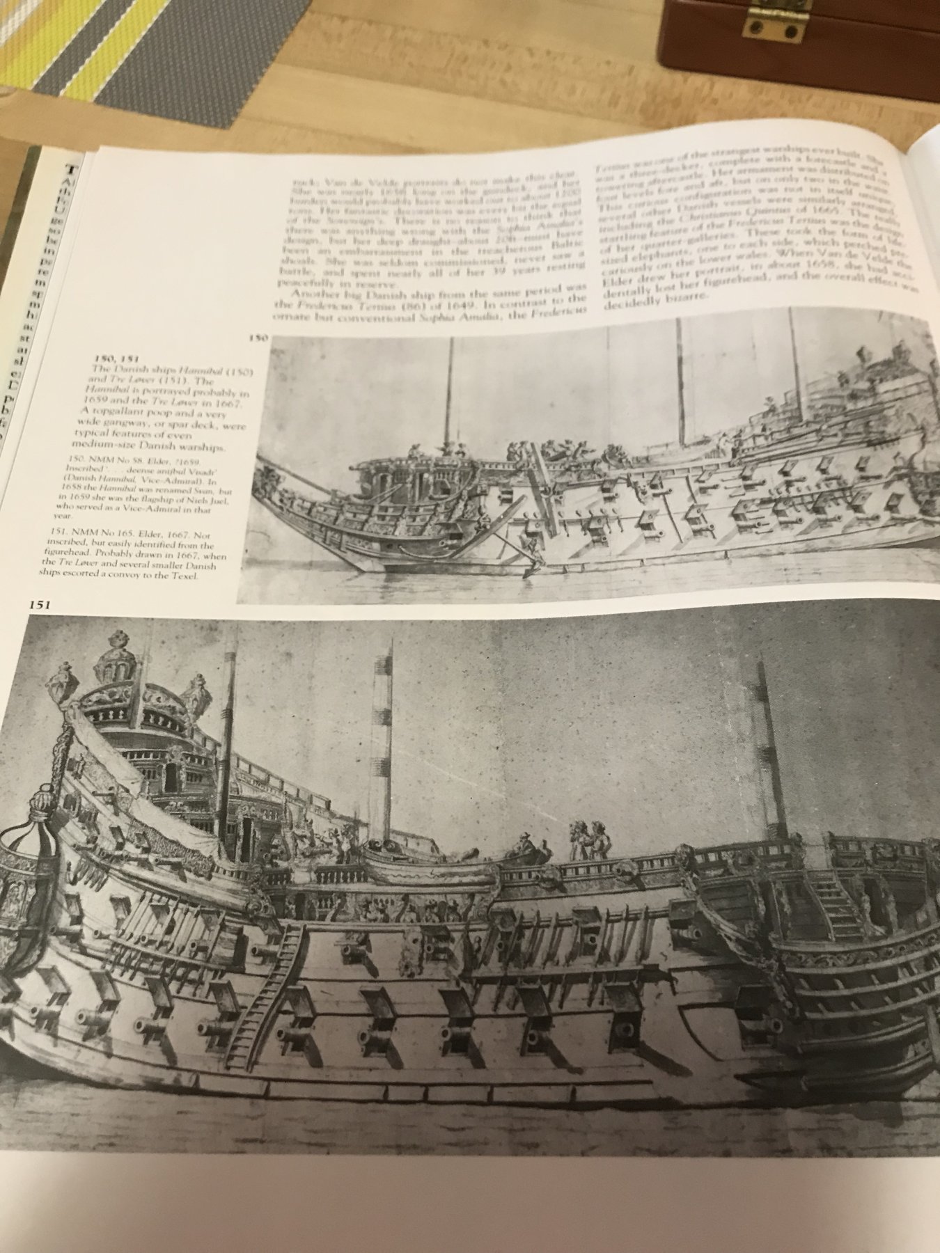
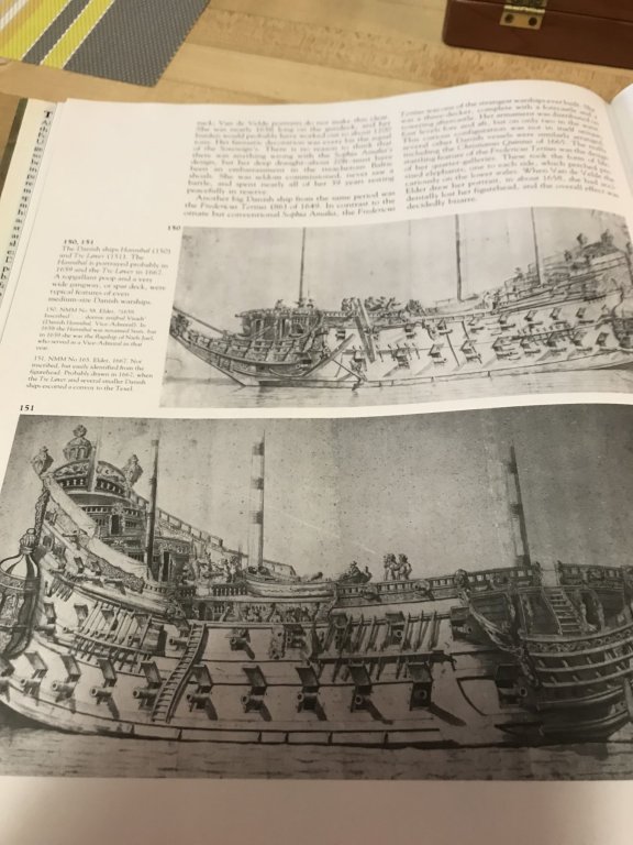
A quick trip to the archives, and there we have it: The Hannibal as she was in 1659, and the Tre Lover as she was in 1667. Both of these ships have much earlier origins - closer to the time of La Couronne. And given the cross-pollination of Continental shipyards, there is little reason NOT to believe that the French did the same. Happy holidays!!
- 213 replies
-
- 5
-
-
- la couronne
- 74 gun
- (and 2 more)
-
Yeah, that portrait is interesting. I remember seeing it once, in a bound edition of something pertaining to historic sailing ships, but never again until now. It appears to be a modern (20th C.) rendering, as it does not follow the conventions of 17th C. maritime artists. It seems to agree with many known details of La Couronne, though I share the same confusion about Le Saint Louis. So far as I understand it, that waist deck would be sufficiently supported to carry the launch, but I would have to go searching for examples to verify that that was, indeed, done. Right now, I am vaguely remembering that this may have been Danish practice around mid-Century.
- 213 replies
-
- 4
-
-
- la couronne
- 74 gun
- (and 2 more)
-
Wow Don - great link!! These cannon look almost se good as the ones Neko and Michel had cast. I’ll have to look into whether using three of the smaller sizes will work for my 1:100 scale. Good looking out!! And happy holidays!!
-
Just leafing through this build, and I just wanted to say what beautiful, clean work you do!
-
I was thinking of you recently, when I found this pic on the net: https://pin.it/4w6fiegh3b7mtf You have done a masterful job here, Vic! This has breen one of the best and most resourceful builds that I have had the pleasure to follow, and I am really stoked to see her on the water. Will you keep this model, or do you have a buyer for her?
- 213 replies
-
- 3
-
-
- la couronne
- 74 gun
- (and 2 more)
-
Ken, your build was a pleasure to watch, and many of your resourceful techniques will serve me well on my own projects. The ship really came out beautifully, and you should be justifiably proud of a job well done. I’m looking forward to whatever your next project may be.
-
Oh, just a teensy-weensy little update 😉. Dan, that’s more progress than I post in five updates on my log! All superbly well done, and I agree that the bright hand rails are a nice touch. Rest yourself for the nitty gritty.
- 287 replies
-
- 2
-
-
- michelangelo
- ocean liner
- (and 1 more)
-
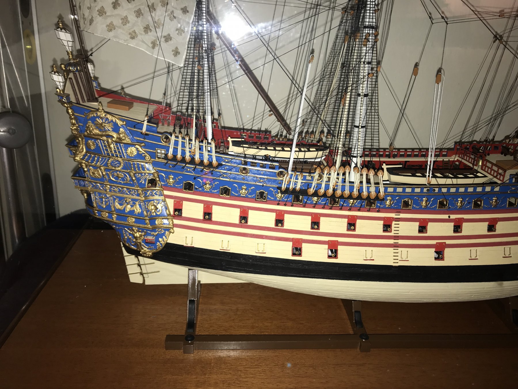
I hear what you are saying about keeping some variety from one tier to the next, but in my opinion, this is largely accomplished by the varying ornament of the stern balcony railings. The mitered panel surrounds are a good argument for consistency on that particular detail. As for the stern paint scheme - like you, I have been mulling over the water colored draft of Berain’s stern, which appears to show a very faded red color for most of the stern, with ultra-marine accent on the tafferal. A while back, J.C. Lemineur suggested to me that it was more likely that all of SR’s upper bulwarks were painted something like Vasa red, rather than ultra-marine. Yet there are first-hand descriptions of the ship that confirm a black boot-top along the lower main wales, ventre-de-biche along the lower and middle batteries, and royal blue upper bulwarks. Personally, while I will incorporate two shades of blue into my upper bulwark broadsides, I am strongly considering the use of something vivid, like Vasa red, for the stern, which would also be accented with ultra-marine blue in a way that is consistent with my use of this color as an accent on my broadsides. In my vue, there is at least a contemporary document to suggest that this was possible/plausible, and I have yet to see the ship modeled in that color scheme, so I like the uniqueness of that presentation. The aspect of that presentation that I haven’t completely figured out yet, is where the middle-balcony wraps to the quarter gallery. On your model, EJ, the lower balcony also wraps to the quarters, so this suggests the need for using blue in the right spots to create a natural transition between the two colors.
-
EJ, the middle tier really looks fantastic. I really like your layered approach to adding in the details. In particular, Inlike the beveled moukdings that frame the lower panels of the middle tier. The mitered corners look really great and finished. All of this adds tremendously to the appearance of the stern and makes a great base for the ornamental accents tyat are soon to come. I wonder, though, whether you will re-work the upper tier to match this middle tier, or will those panels receive a different treatment?
-
Planking coming along beautifully, Don. Having never done it before, it seems to me that getting around a curved transom, like that, is a little more tricky than it may appear. Is it necessary to back-bevel the top edges of the planks, in this area, to keep the seams tight?
-
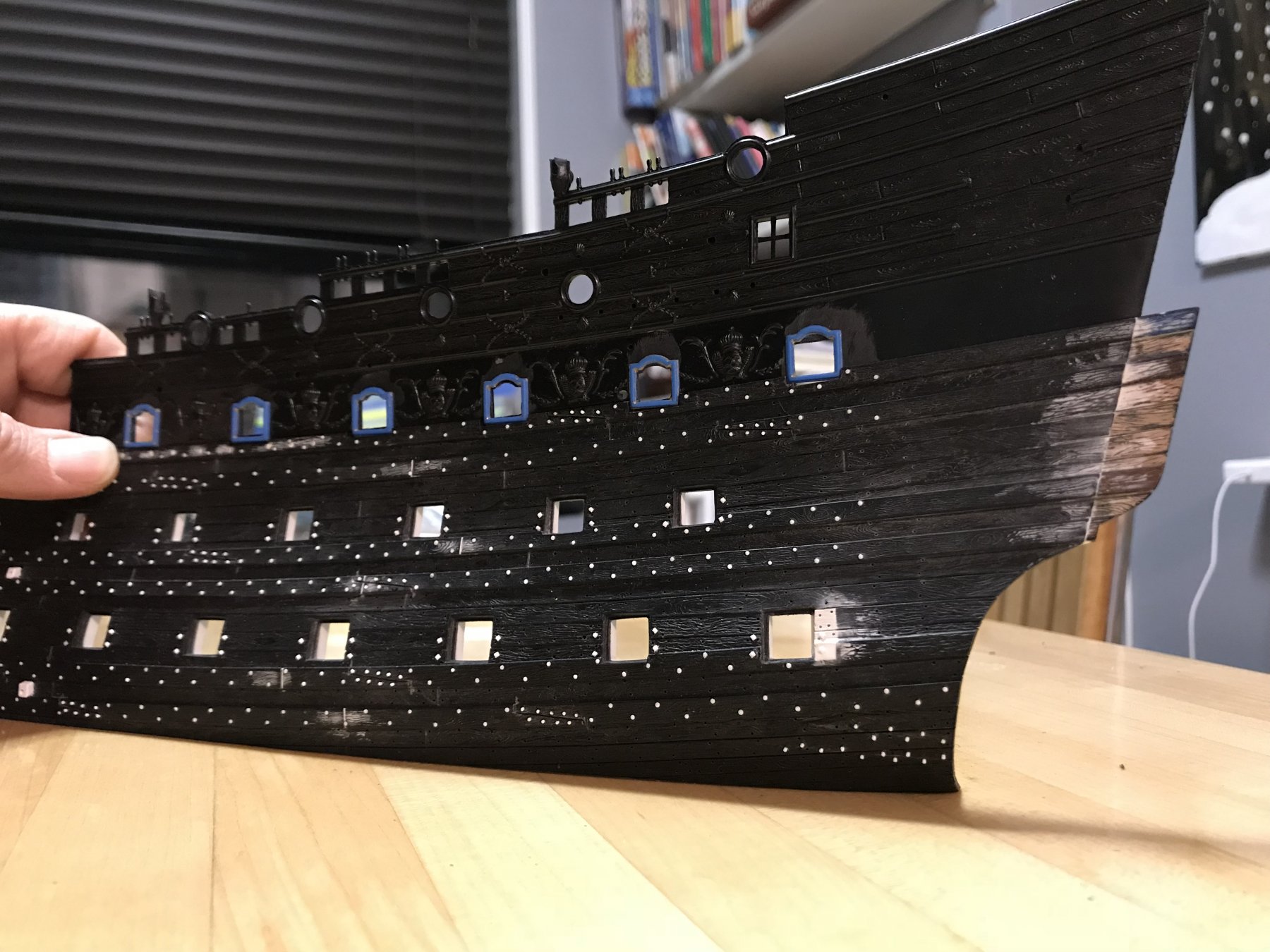
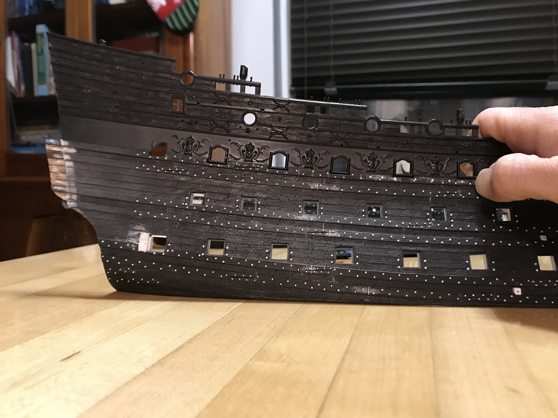
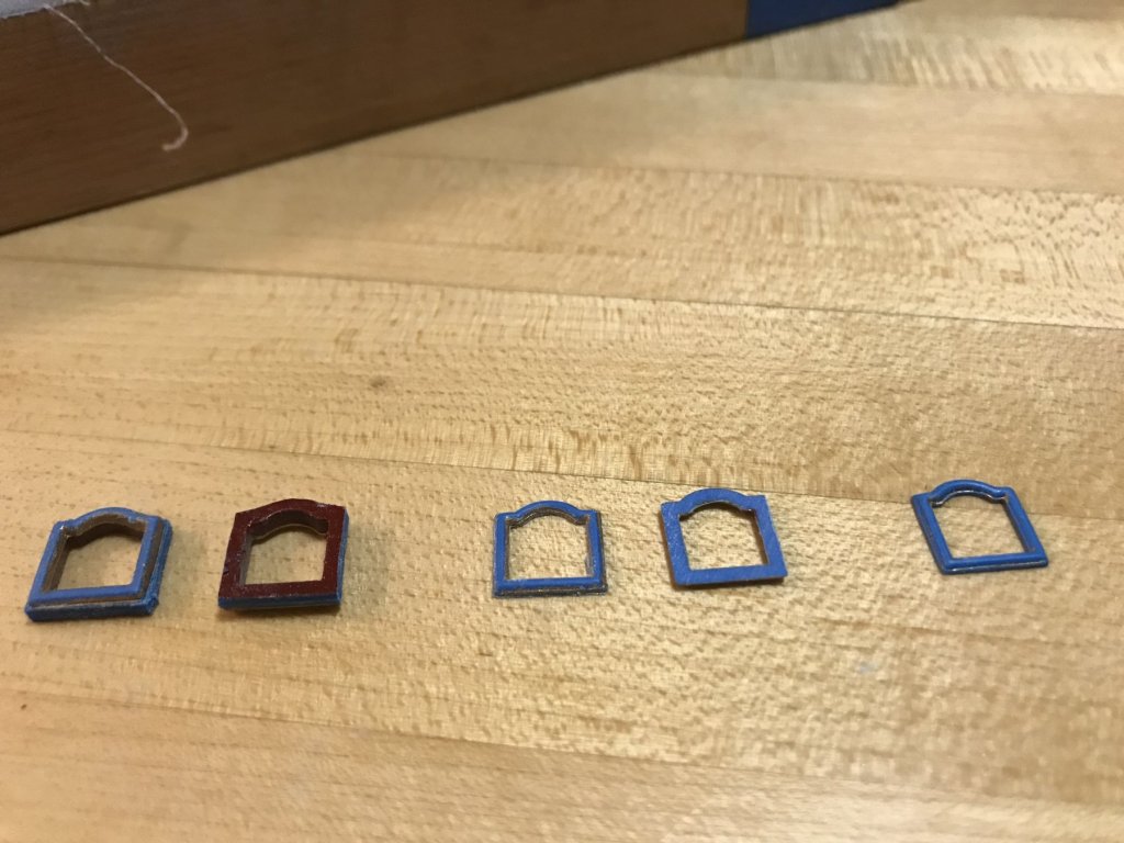
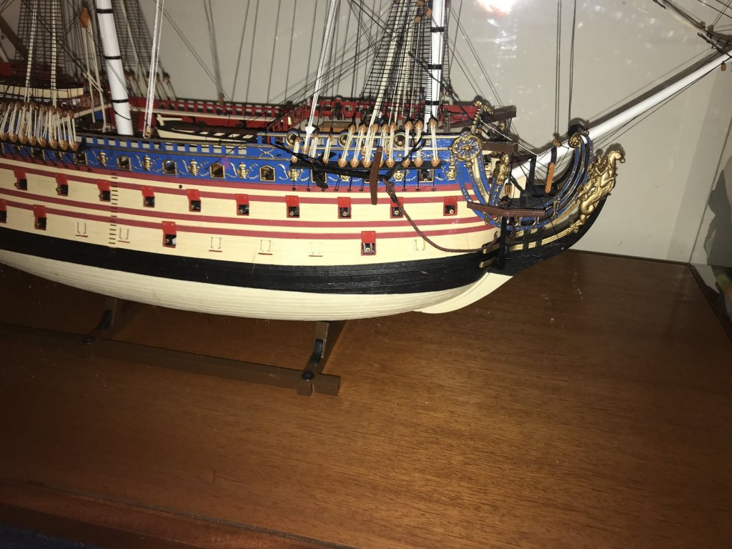
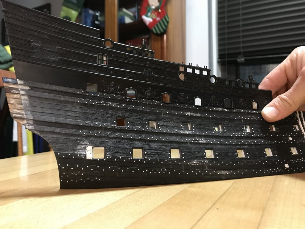
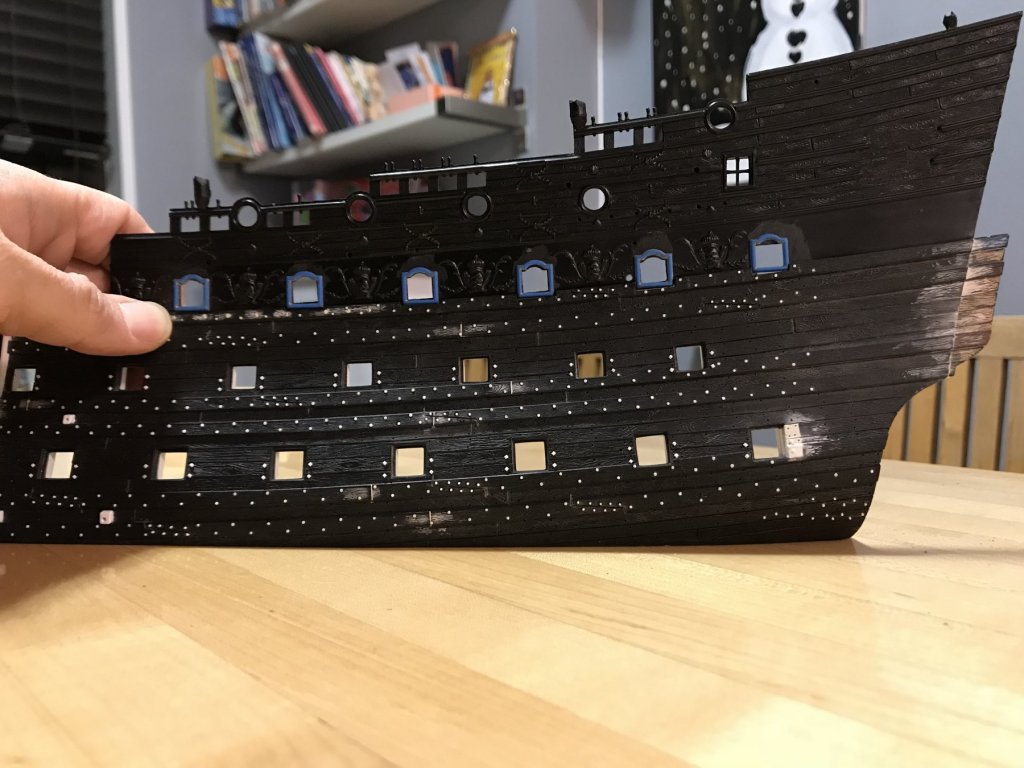
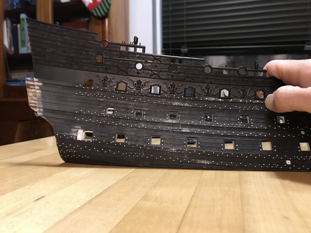
A while back, Dan had brought to my attention the fact that the main deck ports, especially aft, run perpendicular with the sheer of the wales, but not plumb with the underlying framing, as they should be. Here is a shot of my first SR, to illustrate the point: The problem also exists in the bow, but oddly enough the middle and lower deck ports, in this forward part of the hull are also out of plumb. I suspect that to fix the main deck ports, in the fore channel area, would actually end up looking more wrong because of what is going on underneath it: So, with that in mind, I have decided to replace the port frames for the six gunports, aft of the waist ladder. Once again, Henry has come to the rescue! I am salvaging port frames from his spare upper bulwarks. The essential process is to rough-cut them out with a scroll saw, and then use the drum sander attachment, in the Dremel, to get pretty close to the port edges first, and then waste away the backside until I am within a light 1/32” of being left with the frame alone. Then I work the frames, back and forth on an 80-grit block until the background disappears. At the very outset, I had rubbed away most of the gold paint (very efficiently) with a maroon ScotchBright pad. With the frames extricated, I then used the tip of a #11 blade to scrape away most of the remaining paint from the frame edges and the delicate moulded crevices. This is, by far, the most hateful step in the process. That being said, I can do five frames in a night (a couple of hours) - start to finish. In all, I cleaned 14, just to have two extra to choose from. Here is an array of the process: I started with the port side; each time I introduce a modification, I try to alternate the side I start on so that one side of the ship does not end up looking significantly or at least perceptibly better than the other. My technique improves as I go What I spent the most time on, was getting the upper bulwark piece to sit snugly in it’s rabbet. That has to be where it’s going to go before setting the frames. The first time I built this model, I had to fill a significant gap all along the length of the upper bulwark. This time around, the fills will be minimal. Here are the port frames installed and as they appear next to the ports below: It is a very slight adjustment, and it may seem that relative to the window above it, that I didn’t tilt them quite plumb enough. I did, however, manipulate the first two before the glue set, and any further just didn’t look right with the other gunports. For comparison’s sake, here is the starboard side: I still have to fair the interior edges of the port frames with a file and putty. On the finished model, this will be a detail that you will never notice. But without it, astute eyes have noticed and will continue to do so.


- 2,699 replies
-
- 10
-
-
- heller
- soleil royal
- (and 9 more)
-
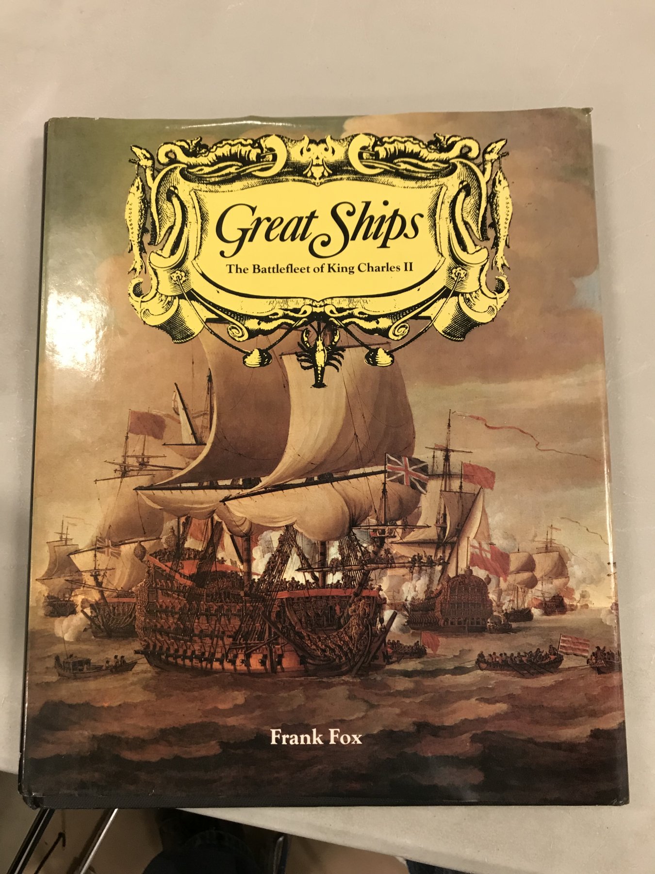
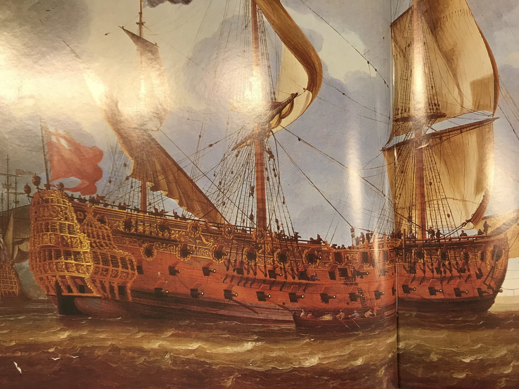
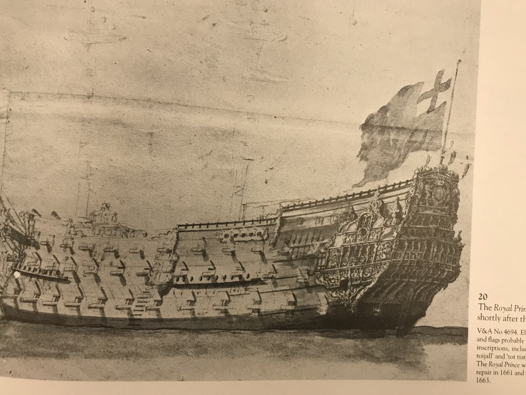
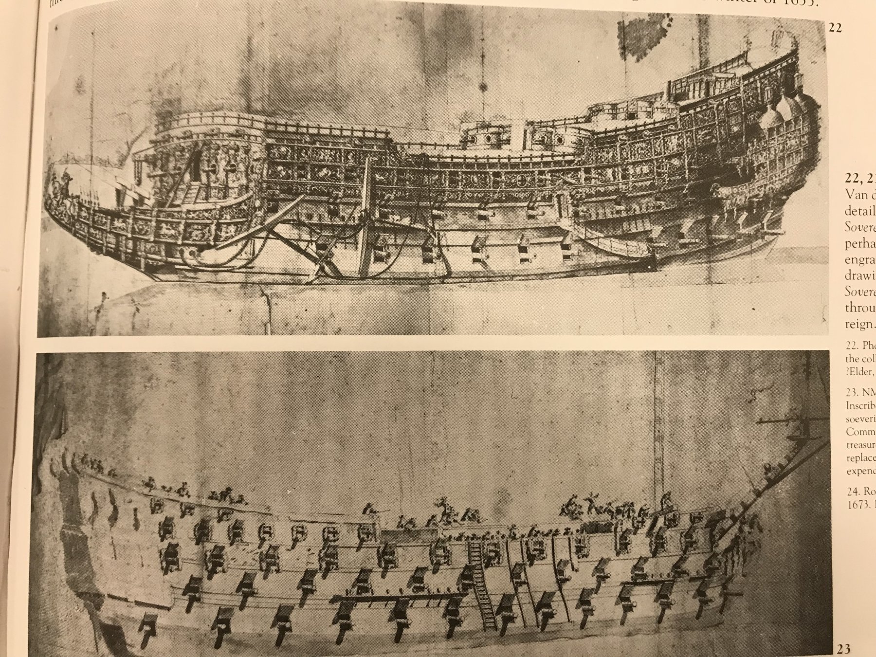
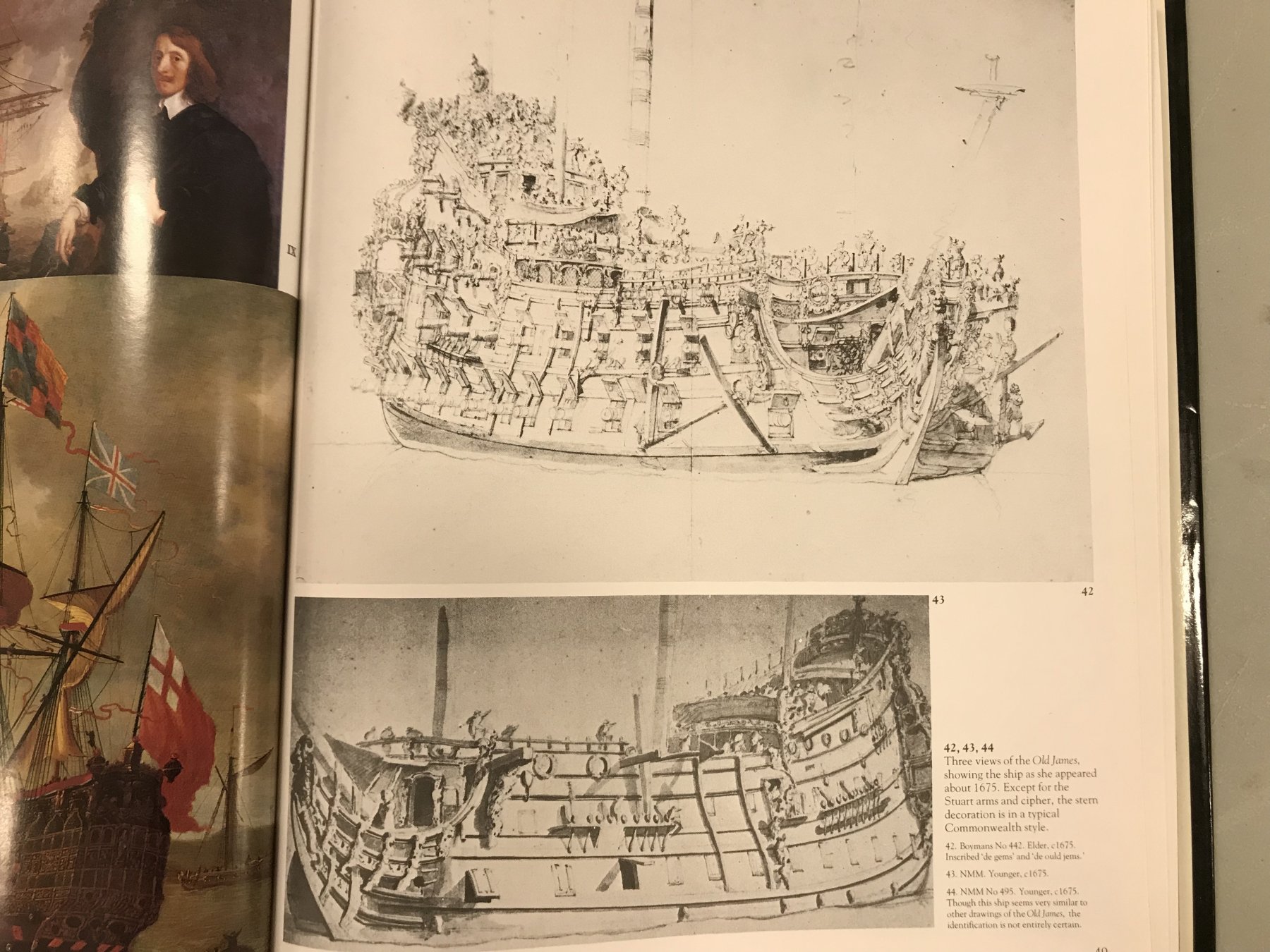
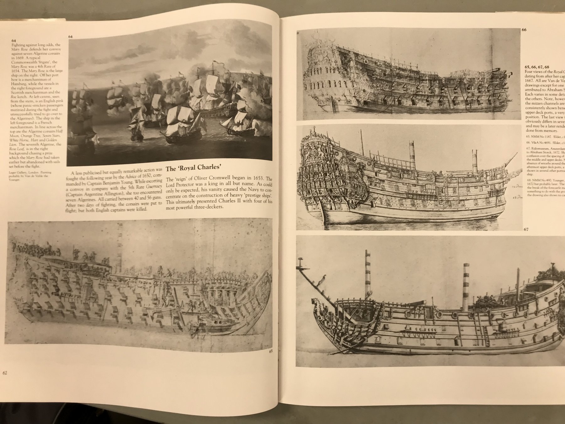
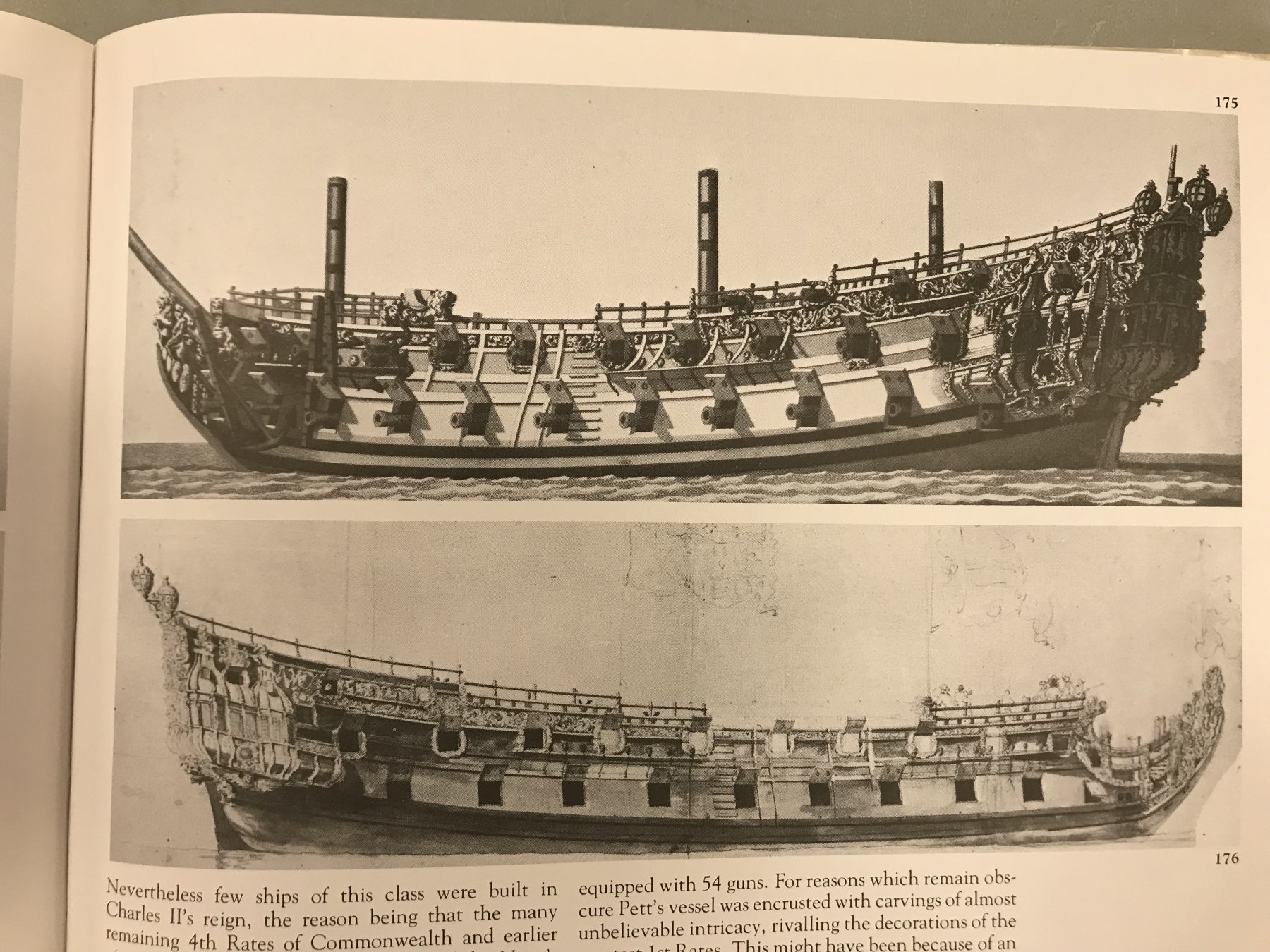
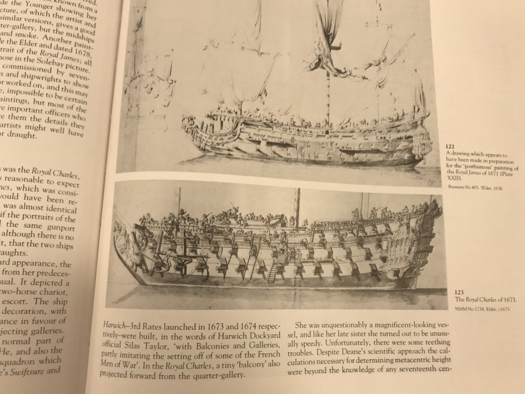
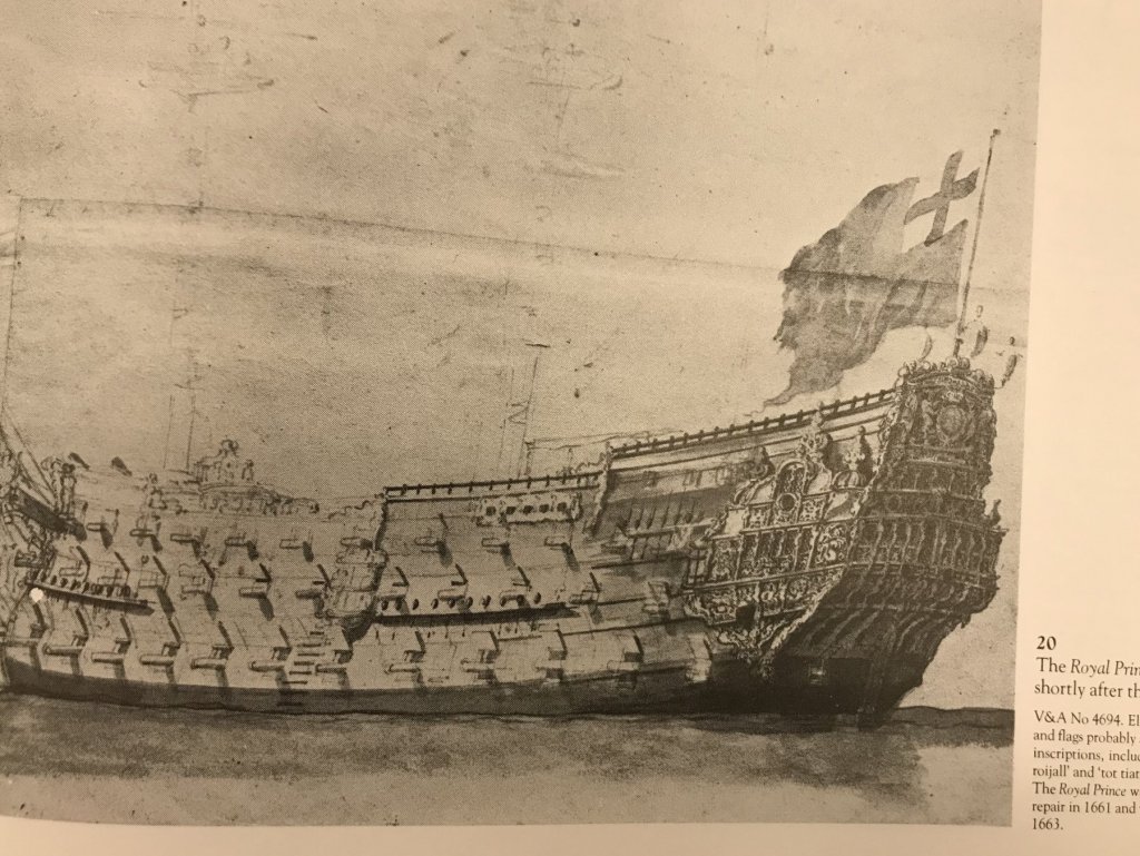
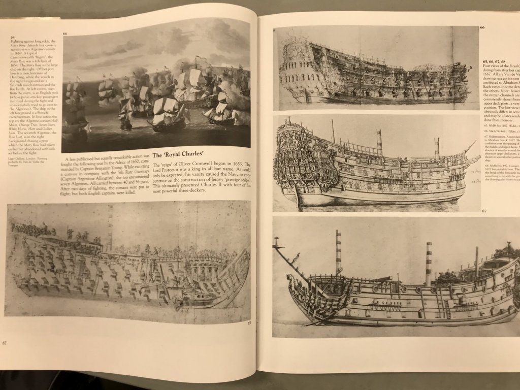
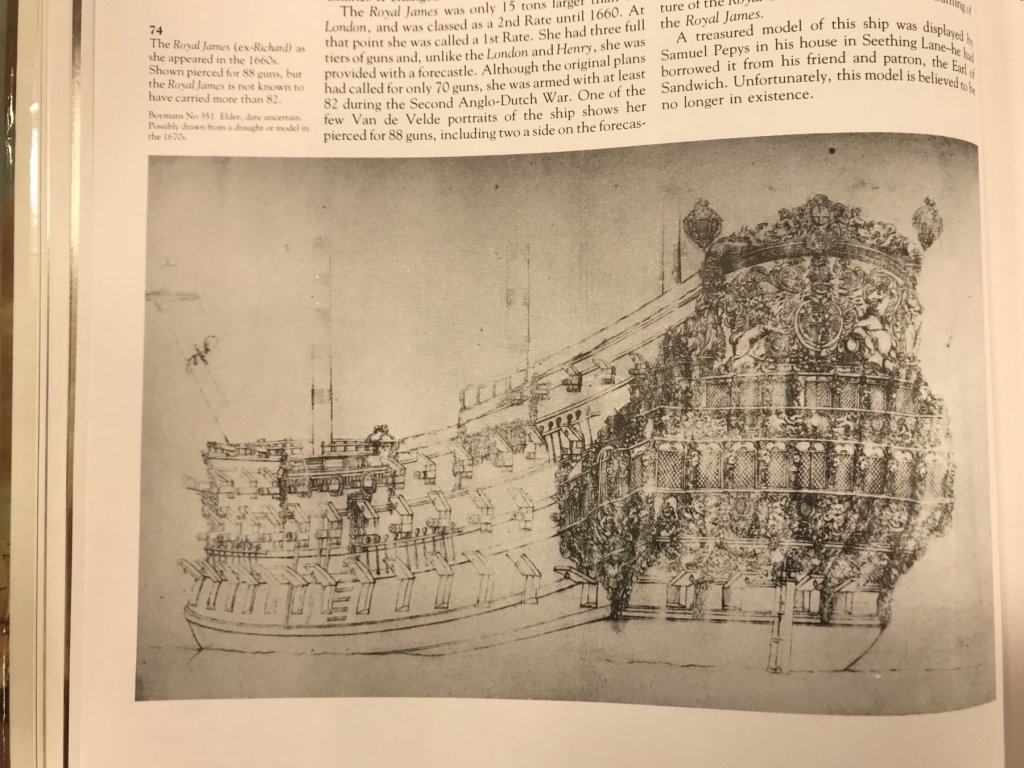
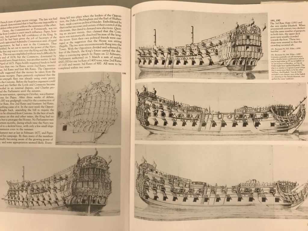
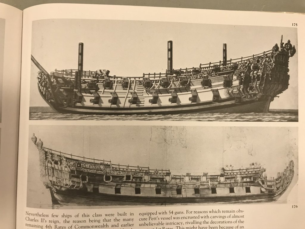
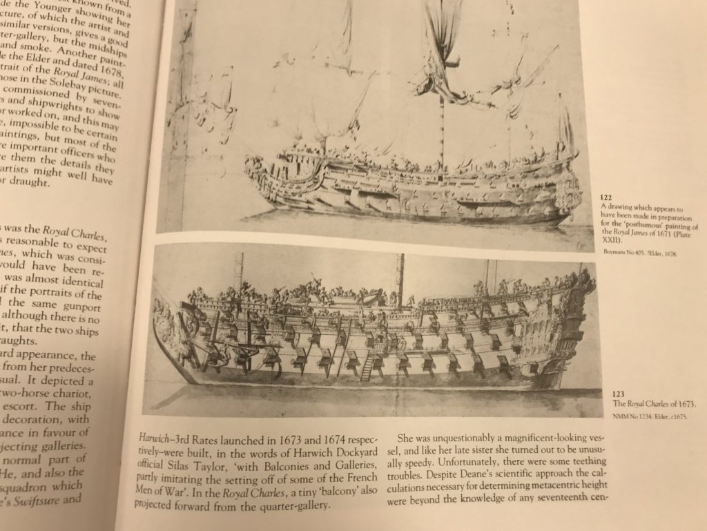
Here’s a little photo essay of my most recent addition to the library. I was first made aware of this title, earlier in the year, when Dan Pariser showed it to me. When I first looked on Amazon, used copies were ranging anywhere from $150 - $500. I waited a while and found this copy for just less than $100. Aside from some light wear on the dust jacket, it is in near perfect condition. This book is teeming with high resolution prints of Van de Velde ship portraits that are so much clearer than most others I have seen. The focus is on the development of the British navy after the Restoration of Charles II. The book features many of the important, known first snd second rate ships, but also does a good job of illuminating the smaller third through fifth rate ships. This was the heyday of English baroque ornamentation and the design underpinnings of much of what would follow in English naval architecture, over the next 150 years. It is such a fantastic resource, which chronicles the modification history of a number of important ships. I can’t recommend it highly enough for gleaning the small details that make a good model great. Above, the Royal Prince of 1610, much altered after her mid-century re-fit The Prince of 1670, shown with an elaborate (perhaps painted) frieze all along her upper bulwarks The Sovereign of the Seas as she originally appeared in 1637, and then following a significant modernization. I prefer her re-fit appearance and believe there is enough portraiture of her, in this phase of life, to create a very good model of her. The old James, marvelous detail of the starboard bow. The Royal Charles, ex Nasbey Incredible stern detail of the Royal James The detail of the portraits above has an almost photographic realism to it. And one last Great Ship, but I could keep providing examples - one more amazing than the next. — In build news, I will soon have an update for SR. I’ve been busily extricating arched gun port frames from Henry’s spare upper bulwarks, so that I may plumb the aft run of these ports on my model. It has been a tedious process, but well worth the effort. I will photograph my first SR, and the straightened ports for the sake of comparison.


- 2,699 replies
-
- 8
-
-
- heller
- soleil royal
- (and 9 more)
-
Hi EJ - this is the part of your build that I have been waiting for. Given your modifications, to date, I think it is absolutely necessary to take the extra time to create a custom window layout. Without the additional space for the sixth window, the only option is to reduce their width. I feel your pain, though, as on my own build I am still hoping to avoid having to create new window frames for my six-window layout. If you so choose to, a new layout will also afford you the opportunity to present the unique window shape of each tier, as they are each slightly different. The effort won’t be wasted here.
-
Thanks for the heads’up on the silk flags, Ken. It makes sense that silk would swag nicely like that. Ship’s boats are looking excellent!