Hubac's Historian
-
Posts
3,314 -
Joined
-
Last visited
Content Type
Profiles
Forums
Gallery
Events
Everything posted by Hubac's Historian
-
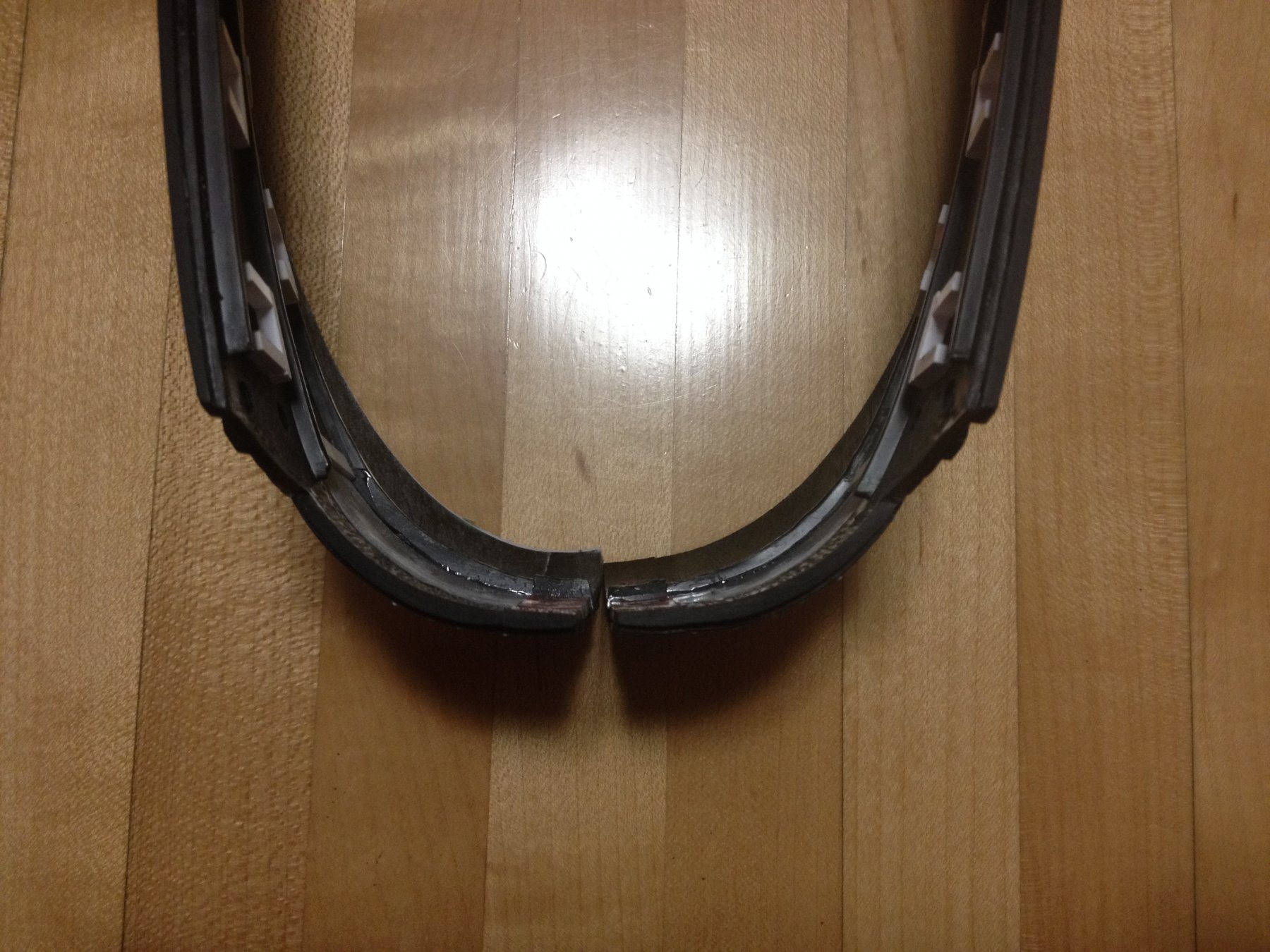
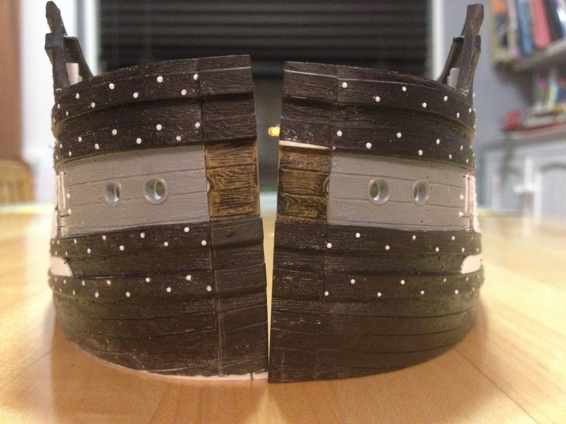
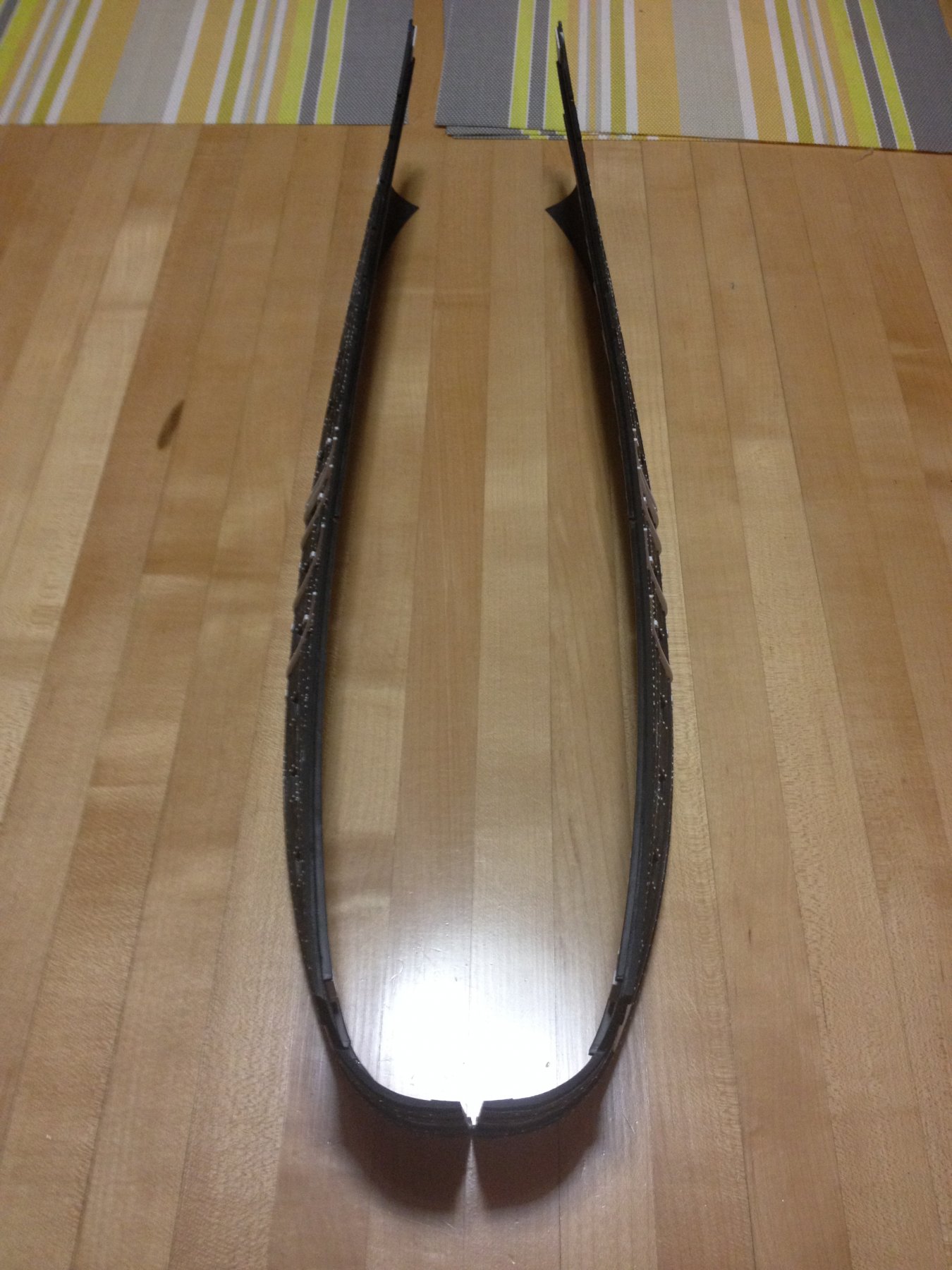
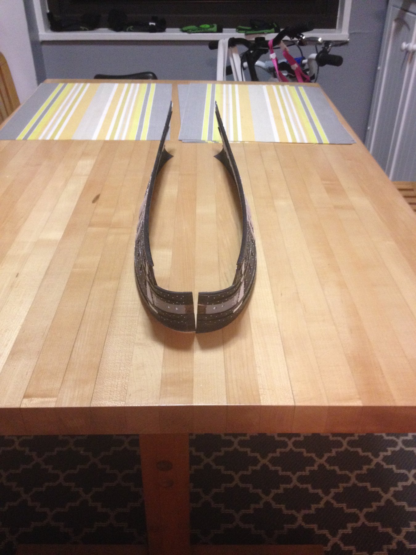
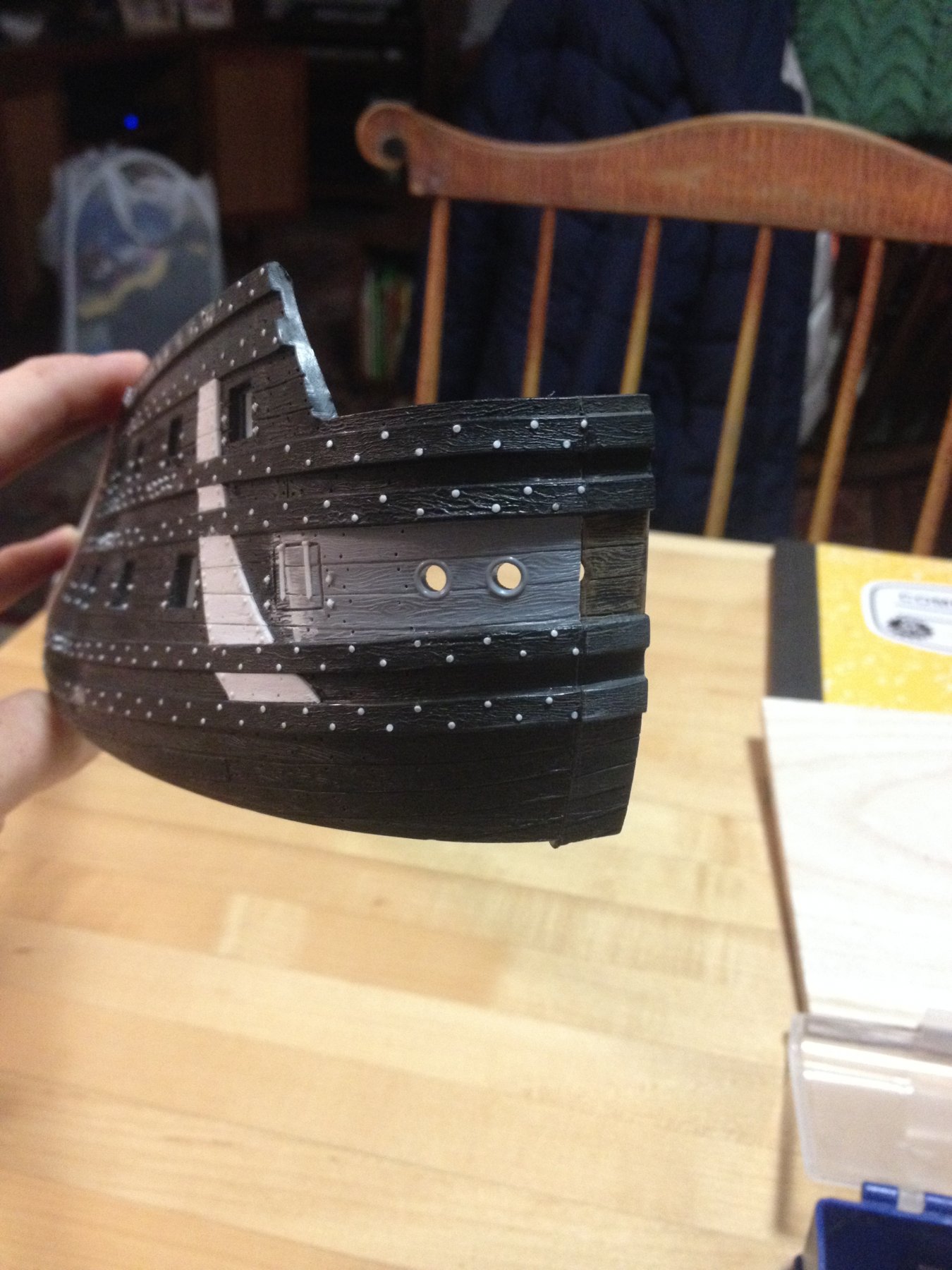
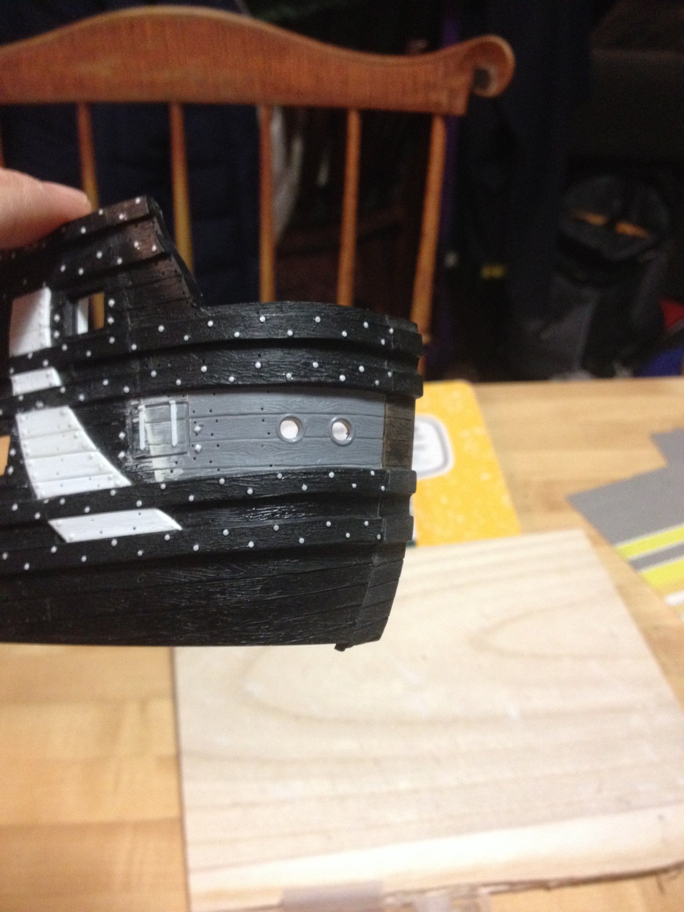
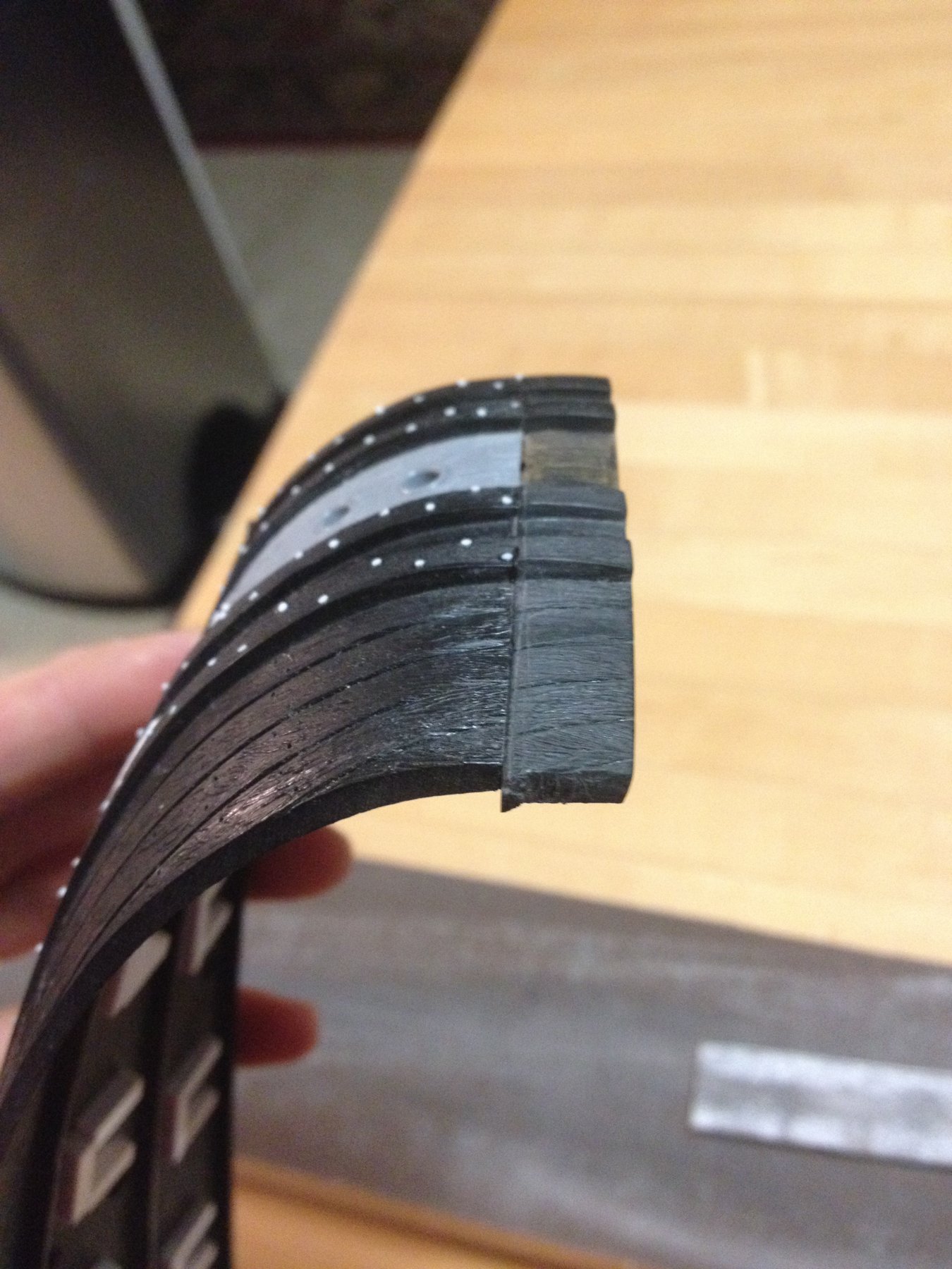
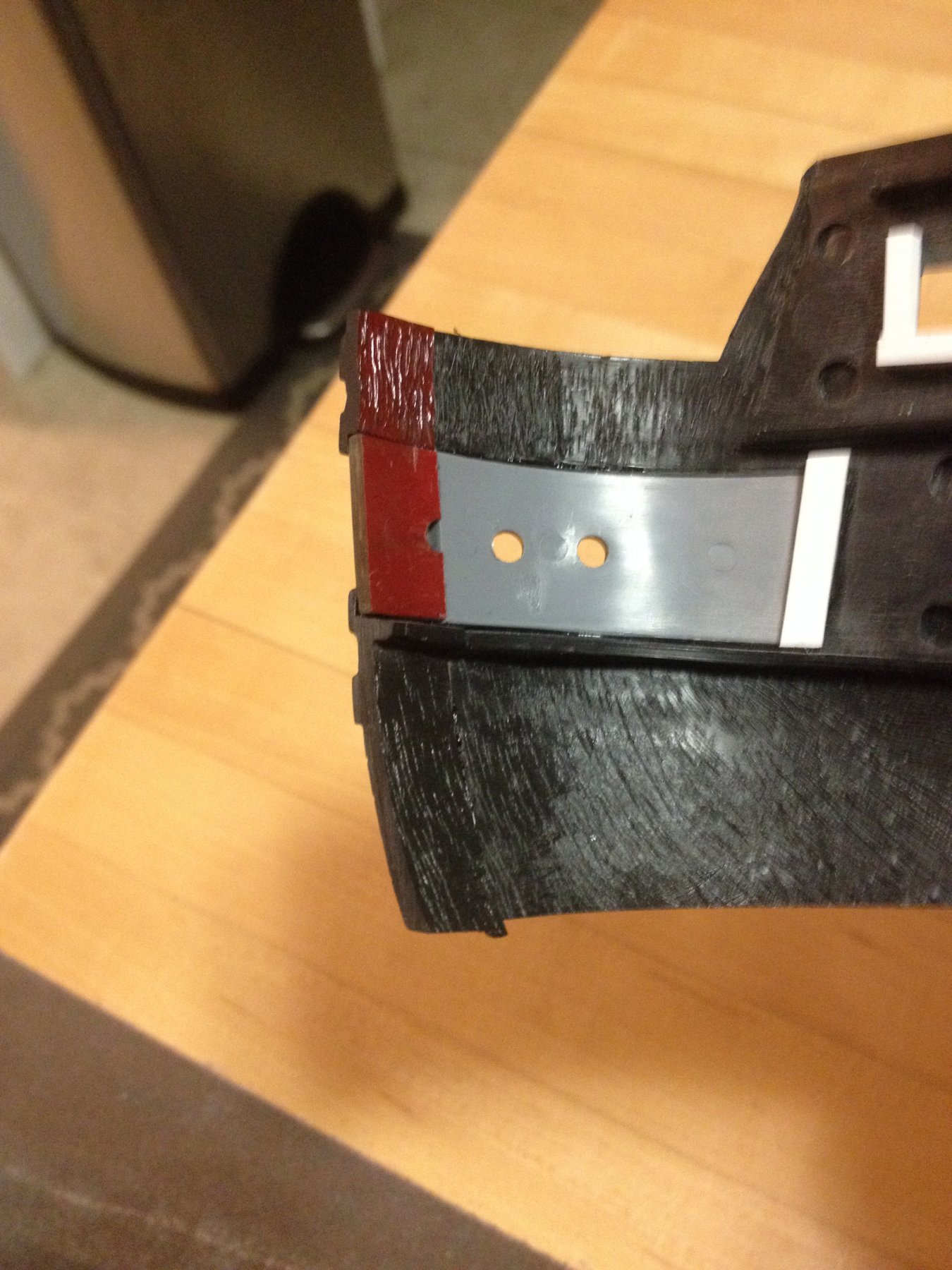
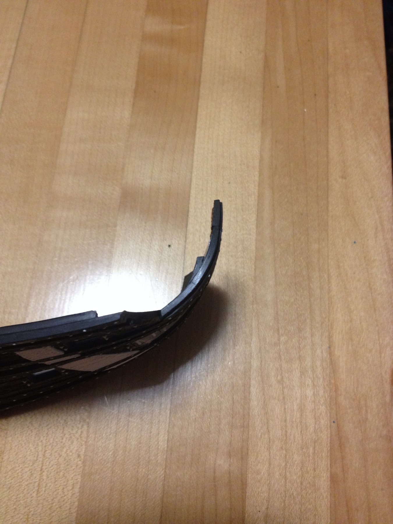
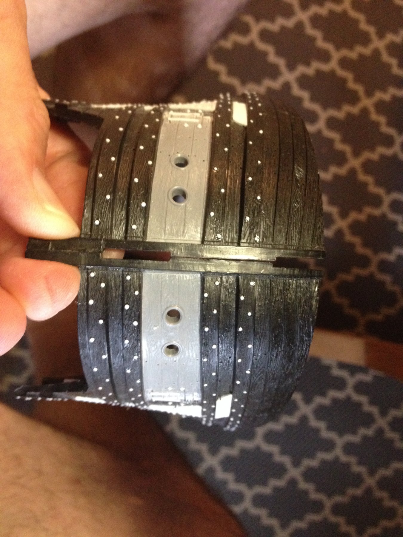
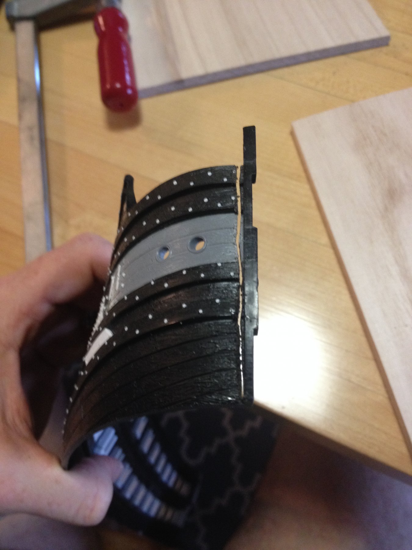
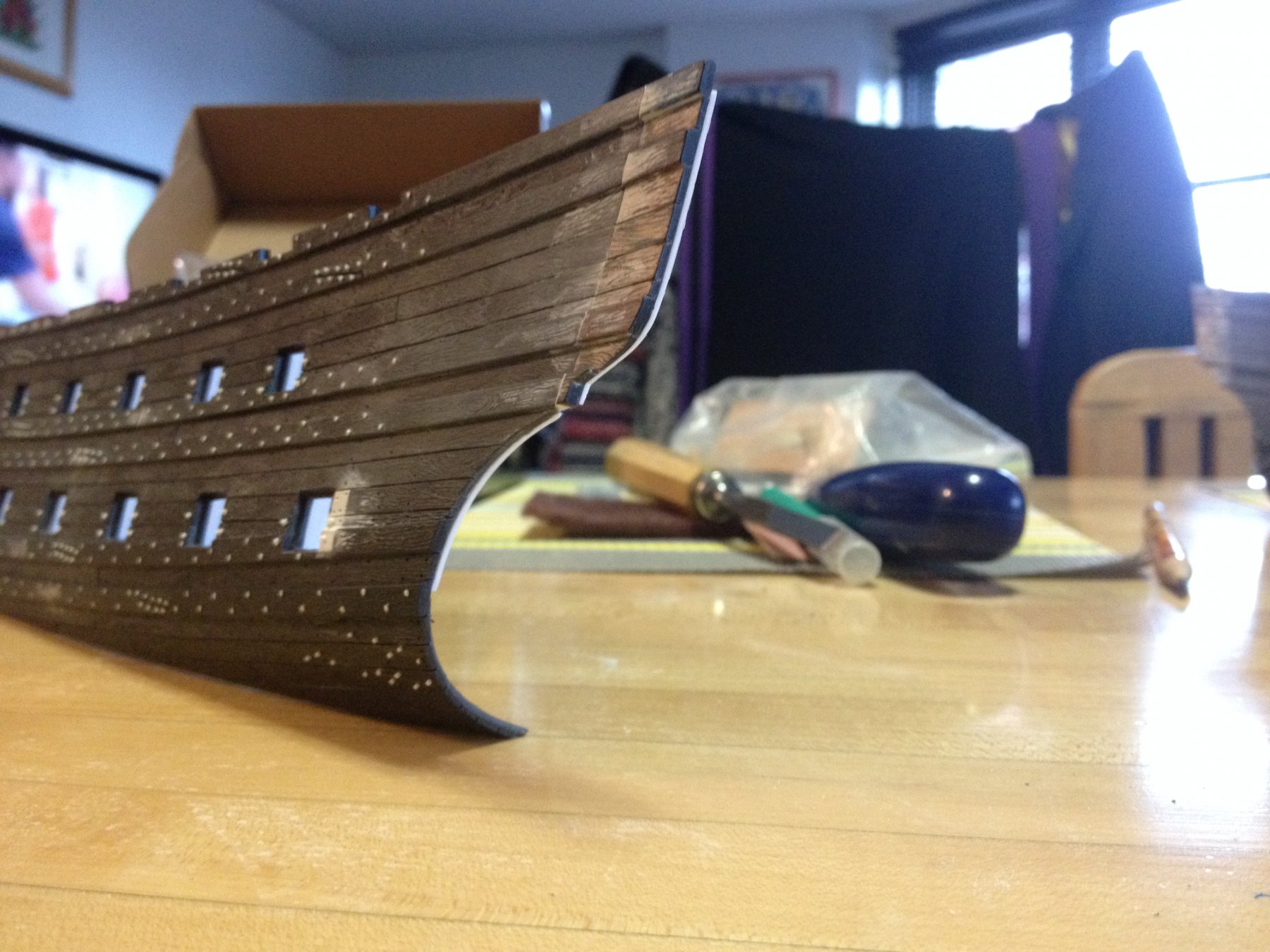
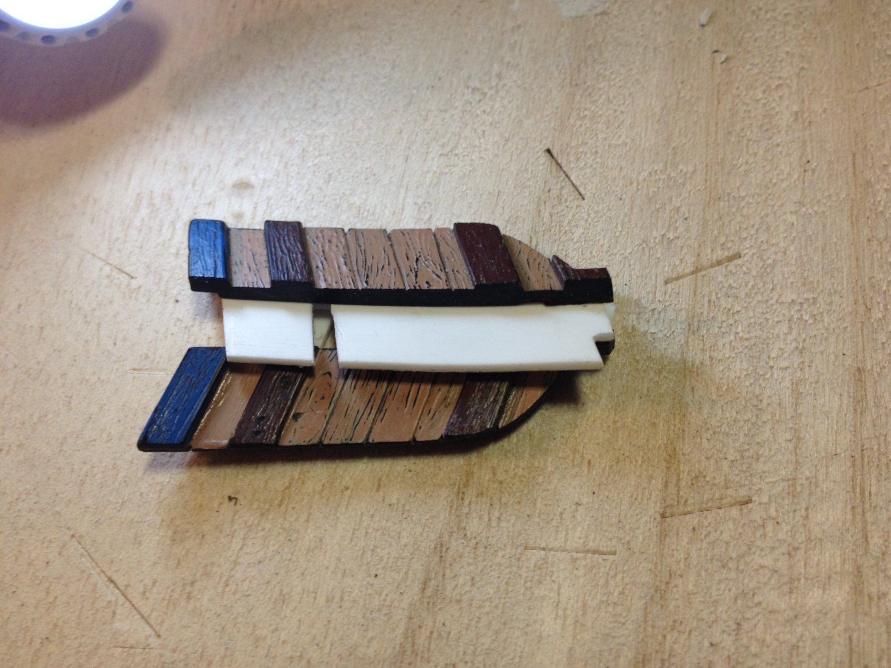
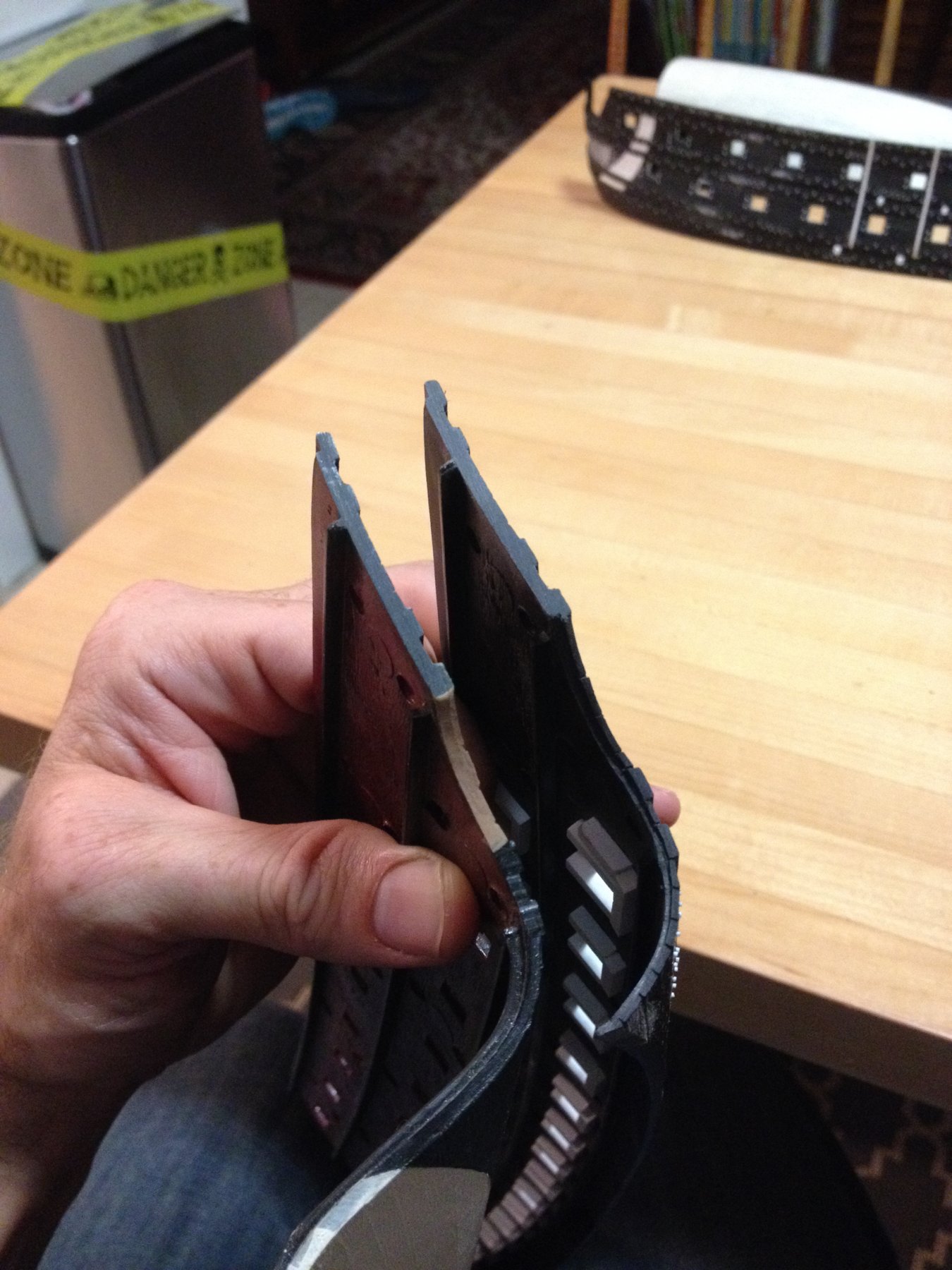
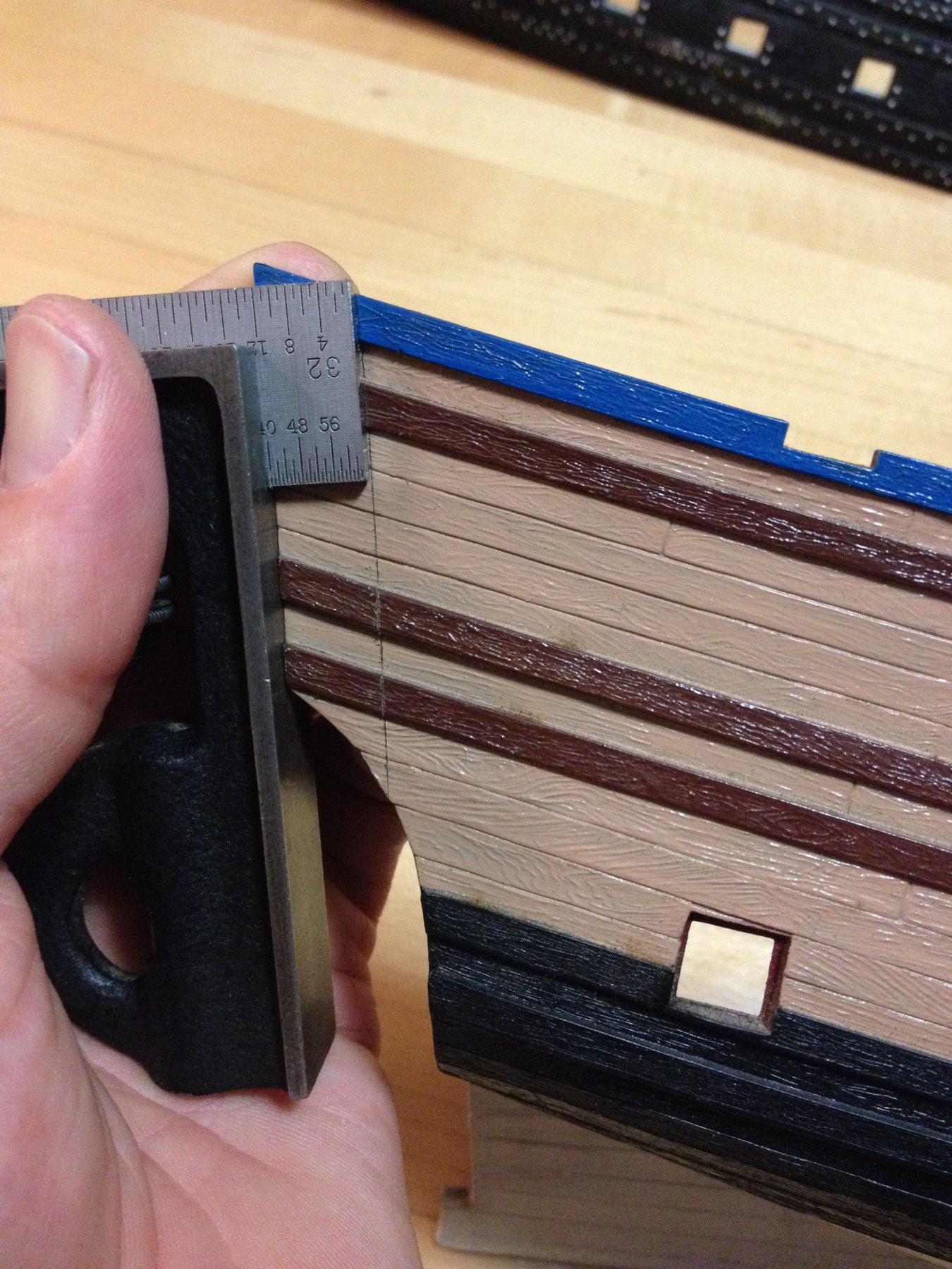
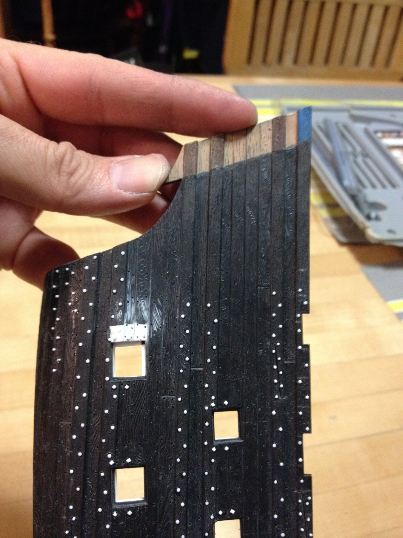
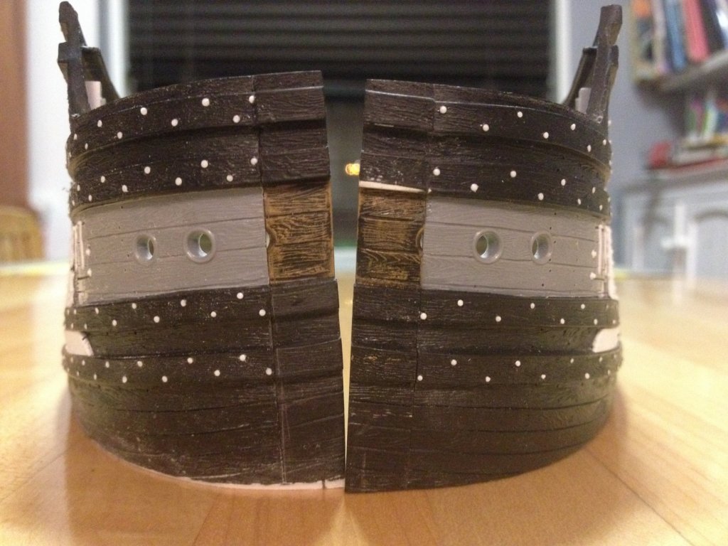
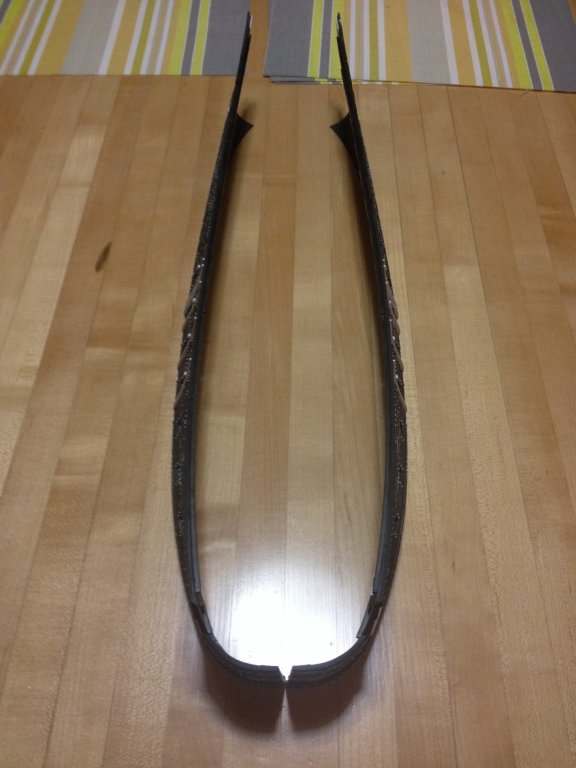
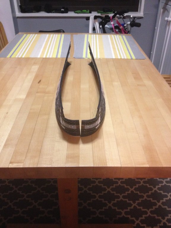
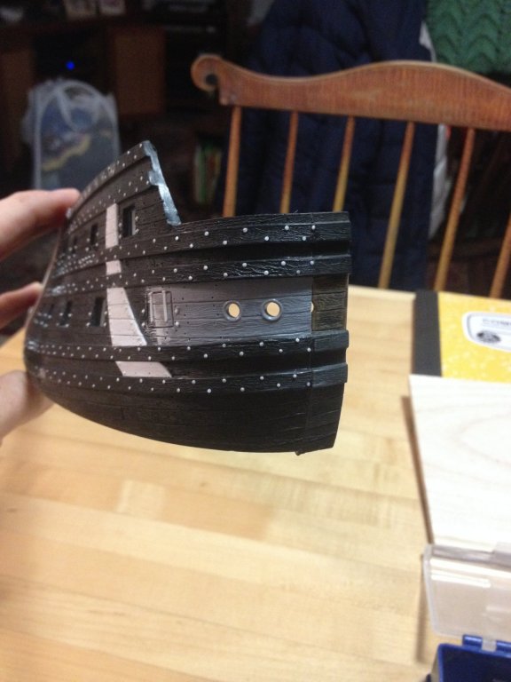
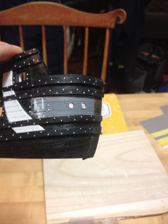
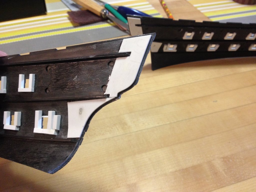
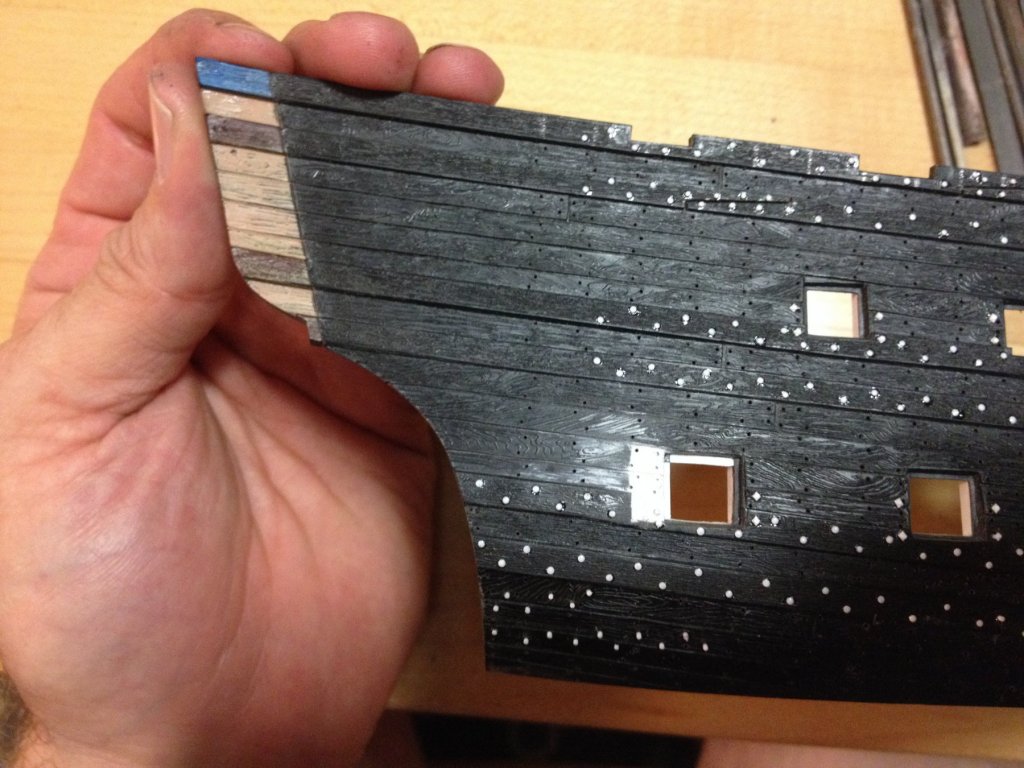
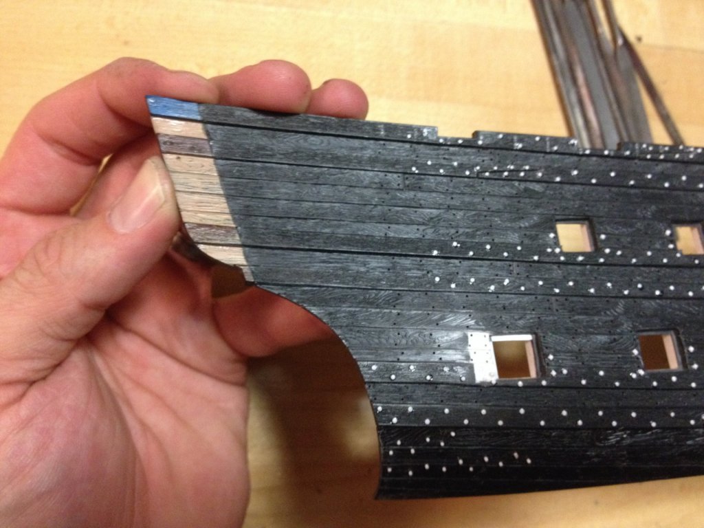
 In answer to my own rhetorical question from the very beginning of this build-log: "What could possibly go wrong?!" Well, as it turns out, quite a bit. My failed assumption was that following the exact same proceedure for the port side, that seemed to work so swimmingly for the starboard side, would yeild the exact same result. Well, it almost worked. Almost. In these next few pictures, I've lined up the top of the bow so that the wales are in the same plane. You can clearly see how the bottom of the port bow, at the waterline, flares forward by a solid 1/8". This creates problems. I suppose there were a few things in play here. For example, in this next shot, you can see that the top two wale strakes of the top third of my bow extension, on the port side, seem to flare more vertically, at the stem, than the starboard side. So far, I've patched in a little squadron white just above the hawser insert and leveled the top line of the beakhead, in an initial effort to help mitigate these differences. You can also see, below, that I shimmed in a little white plastic along the bottom of the starboard hull half because I could not get the thing to sit down on a flat surface. Ultimately, I want a good joint along the hull mounting plate and it's just bad model craft to force the hull to lay flat, hoping the glue will hold; that would only serve to distort the run of the hull, above the waterline. The overlap problem originated, though, as I was sanding this top third extension piece to both the appropriate width and mating angle. I suspect that I was applying just a little too much pressure to the upper end of the piece, tapering what were supposed to remain parallel edges of the extension piece. Consequently, this changed the run of the wales quite enough to be distracting, and I hate these sorts of distractions! For the middle, hawser segment of the port side, I was able to fair the run of the plank seams, and the extensions weren't flagging too far inboard or outboard, so I figured things were back on track. I figured I'd simply add to or subtract from the wale edges to improve symetry from port to starboard. No biggie! Finally, I sanded the lower third to width and to an angle so that it rested neatly upon the hawser piece and seemed to show a fair run of the hull at the waterline. And it was a fair run - more fair, in fact, than that of the starboard side. MY TRAGIC ERROR WAS IN NOT PICKING UP THE STARBOARD SIDE TO MAKE A DIRECT COMPARISON BEFORE GLUING THE PIECE IN PLACE. Had I done so, I would have noticed the discrepancy immediately. So, what to do now? As things stand - if I align the waterline, it pushes the port stern an 1/8" past the starboard side; it simply won't do to have a lop-sided stern! I don't have enough material to cut off the port extensions, fair both mating faces and re-glue. What I can do, though, is take steps to mitigate this difference. One thing that I do have sufficuent material allowance to correct, is to plumb the bow edges at the stem. You can see, at the moment, that the joint is open nearly a 1/4" at the top. In order to do this, I will have to grind away 1/8" to nothing, from the waterline to the top, on the starboard side, and 3/32" to nothing on the port side. This adjustment will still afford me the 1/2" extra, in the stern, that I need above the stern counter. As far as fixing my problem at the bow, on the other hand, these reductions at the waterline cut back the hull towards the original hull - which at one time, in the recent past, mated together perfectly. These tapering reductions to plumb the bow joint may effectively reduce the port side overlap, at the waterline by as much as 1/16". I may, simply, be able to sand back the remaining 1/16" and scribe back in the plank lines, so that the bow curvature matches and the transom edges align with each other. It's a theory. I'm open to suggestions, here. In these next two shots, I've set the hull halves at what will be the appropriate distance at the stern, in order to get a more accurate sense for the aspect of the thing. The current gap at the stem would only be slightly reduced with the stem actually in place. I think that, ultimately, these modifications will result in a more balanced looking model than the standard kit. I like the rake of the tumblehome as it rises above the waterline. I have held the upper stern bulwark in place and it, too, appears to rise at an appropriate angle to the ship's centerline. There's hope, yet for this project!
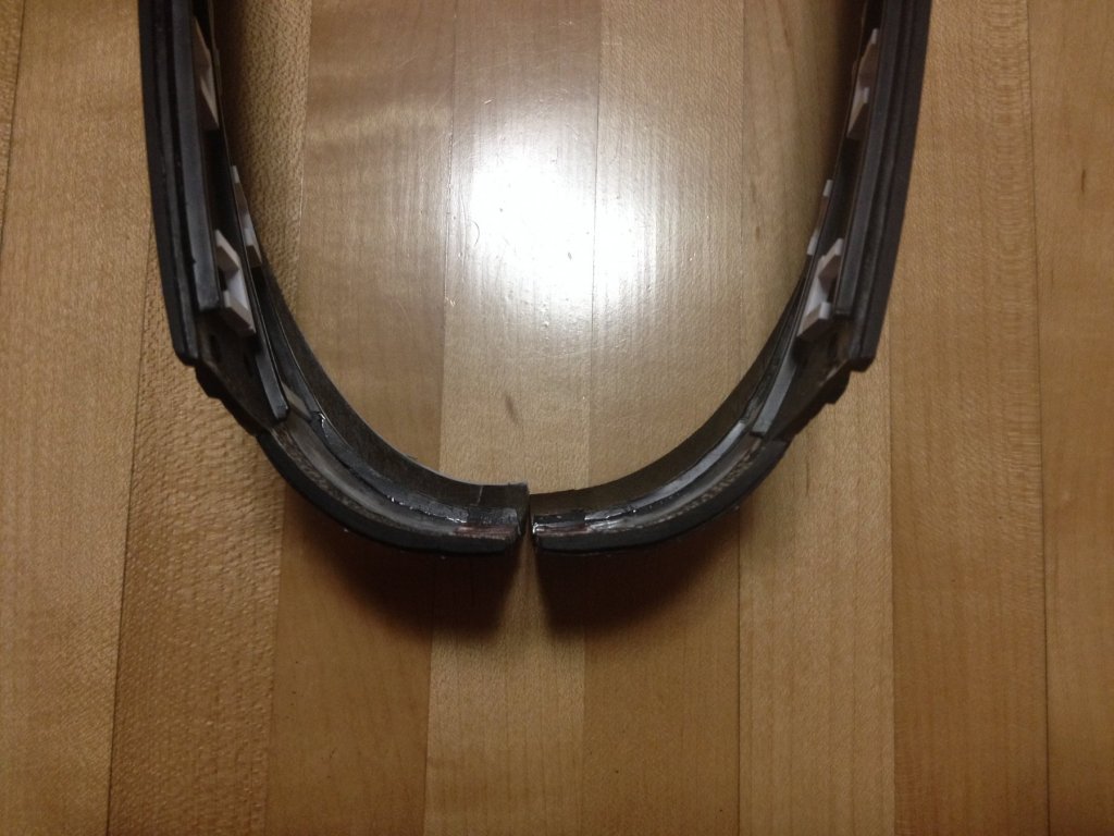
- 2,699 replies
-
- 3
-

-
- heller
- soleil royal
- (and 9 more)
-
The issue with your hand, aside Ken, that is a genius solution to the task of fitting parrels. It looks so good and convincing that I would say that's just a great way to go about it.
-
There is much to look forward to, Henry. Once the bow pieces are in place, faired and the hawsers re-located, I'll fill in my bolt and nail details, where they are missing. Then, the whole detailing/modification process begins all over again with the upper bulwarks where, thanks to you, I will plumb the run of main deck ports. I'll extend the upper bukwarks, at the stern. I will, then, scrape away most of the existing ornament, as well as the narrow sheer strakes, in preparation for the new ornamental frieze. I'll lay in the lattice and carve casting masters for the three types of ornament that will adorn the frieze. After, that, I'll make caprail ornaments and add the tops to the skids, where they connect with the lower hull. following that, I will carve the lower finishing and upper amortissement of the quarter galleries from some species of close-grained, but relatively soft wood. Maybe balsa, but I think something else that is a little more resilliant. Once those are in place, they will need to be detailed. And then, finally, I will begin assembling these parts into a model, building the stern and decks up from scratch, as I go. It's a process. I will get there, eventually. To me, it seems to make the most sense to make most of the major modifications while everything is still un-assembled.
- 2,699 replies
-
- 2
-
-
- heller
- soleil royal
- (and 9 more)
-
Thank you Chapman! I always thought this idea should work, however up until now, this was a project of theoretical optimism. I was prepared to fill-in the blank below the lower main wale, from scratch, if necessary, but I'm just really stoked that I won't have to do that. Thanks for following the build. Many thanks to Henry for donating the extra parts, in the first place.
- 2,699 replies
-
- 2
-
-
- heller
- soleil royal
- (and 9 more)
-
This is really turned out to be such a lovely model, Don. Congrats on a superlative job! If you don't mind, can you please re-state what it is you are using for your decking material - it looks fantastic!
- 653 replies
-
- 3
-
-
- trabakul
- marisstella
- (and 1 more)
-
Alright, well, with just a little fudgery (Mirriam Webster: generous application of Squadron White putty, and re-scribing as needed, and a little reconcilliation of the wale edges) I think this is all going to work out just fine. Interestingly, to me at least, the hull lines faired better below the lower main wale than expected. The plank seams will need to be filled and re-scribed, but the run of the hull is pretty okay. Definitely, working well over-size and in segments was the way to go; I was able to make micro-adjustments, along the way, without feeling the pressure of getting the joint angle and run of the hull correct in one go. Eighty grit paper works the plastic pretty quickly, so mistakes can happen before you know it, when you over-reach. And, it seems, that there is ample extra material to plumb the stem without losing any of the width that I actually need. Good day for the project. The success of the whole thing was riding on this, so I am energized!


- 2,699 replies
-
- 8
-
-
- heller
- soleil royal
- (and 9 more)
-
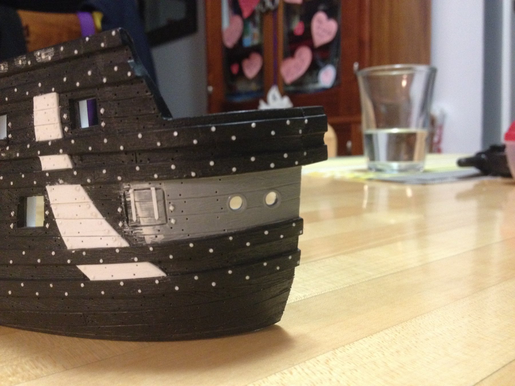
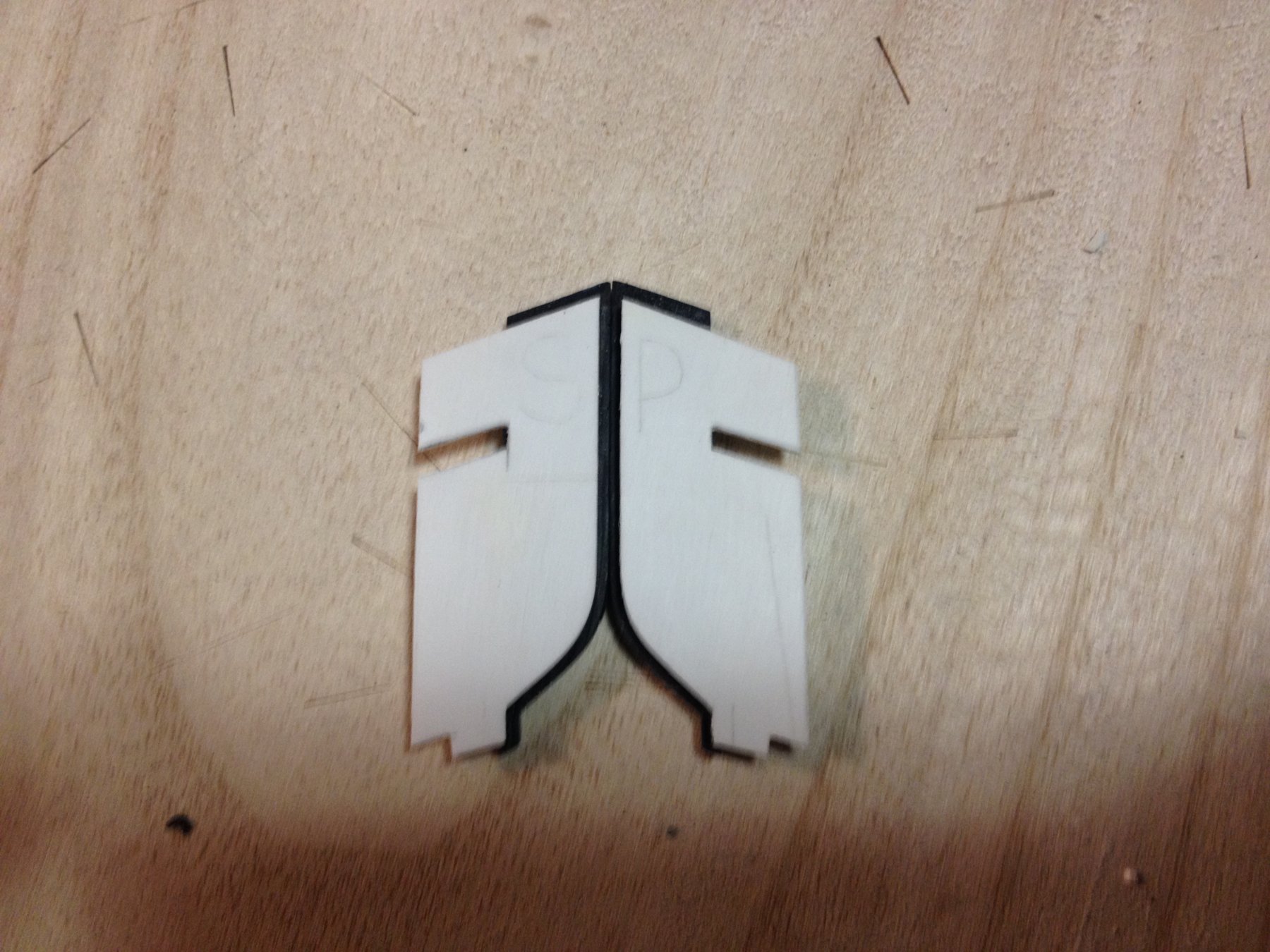
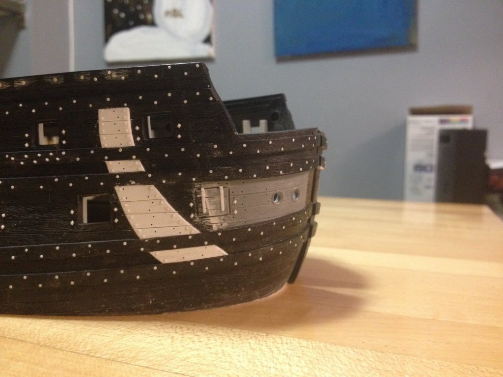
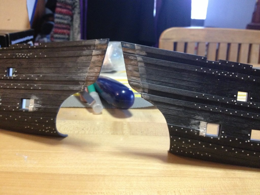
Ultimately, I decided to work in more manageable thirds. This top-most segment is the most important one; It allows me to gauge the angle of the joint, and the subsequent run of the bow line. You can see, in these pictures, that there is a slight depression at the joint. In black plastic, and from most angles, this is not apparent at all. A little putty, though, to fair out the surface, and then it won't be apparent at all - even when painted. Also, bear in mind, that all of this will be heavily overshadowed by the bowsprit and head timbers, etc. I'll fit the middle, hawser segment, so that the stem edge neatly aligns with the stem edge of the top piece; when I have a straight edge, from one piece to the next, that's when I know to stop fairing and fitting (because, previously, when I ground away the stem - I then straightened the edge). Once all three segments are glued in place, I'll flatten the interior back surface of the joint, and re-enforce the joint with sheet styrene. Lastly, I will devise an angled sanding block to true-up the stem joint, so that the stem pieces - once re-attached - run parallell with each other and perpendicular to the table, so that the hull halves glue together nicely and easily, at the stem.


- 2,699 replies
-
- 7
-
-
- heller
- soleil royal
- (and 9 more)
-
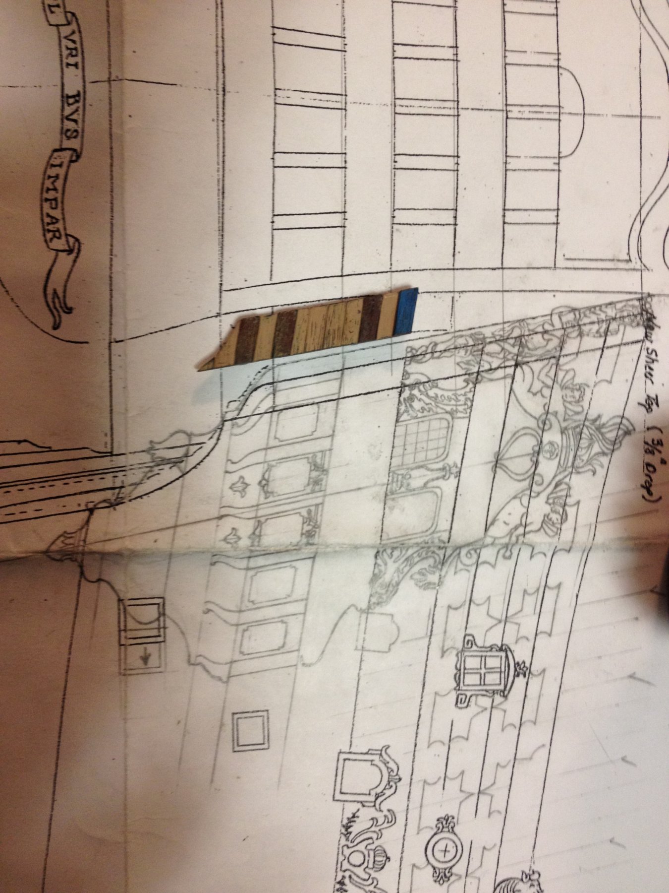
Thank you everyone for stopping by and for your likes and comments. Yes, Cedric, in order to add back the missing sixth window of Berain's design, it was necessary to increase the breadth of the hull, across her beam, by exactly 1/2" (the width of one stern window + one pilaster). It seemed that the most practical way of doing this was by inserting material closest to the stem, where the bow is so bluff as to be nearly flat. Now, as I get into the actual doing of the thing, I can see that it should work seemlessly from the top down to just below the hawser piece. Below that, however, I may run into a little trouble with the compound curvature (both toward the centerline, and arcing around toward the stem) of the hull. Further complicating the surgery is what Henry once joked as The Battle of Bar Floor. While constructing his model, many years ago, he dropped one hull half with the hawser insert already glued in. This cracked the thin stem piece (not important to me), but also spoiled the glue bond along the forward half of the hawser insert. Right now, I'm debating whether to pry the hawser inserts loose and re-fit and glue them, before cutting out my 5/16" extension pieces, or alternatively, grinding away the un-needed stem piece and then cutting away the extension pieces into three loose segments. The second approach may allow me to manipulate whatever adjustments I need to make on the lower segment more easily. Or, it may just make the whole thing infinitely more complicated. Decision TBD.
- 2,699 replies
-
- 2
-
-
- heller
- soleil royal
- (and 9 more)
-
No doubt that would be helpful, although one would have to account for the saw back in setting up for the cut. I have one more critical cut to make, which is the opposite of what I just did here. When it comes to cutting out the extension pieces from Henry's model, I will be able to make really approximate cuts that are way over size and just fair my way back to where I need to be. I may try to square the stem, so that it is properly perpendicular to the table surface, along the ship's centerline; ever since I cut away the lower hull halves, the inherent warping of the hull has resulted in my stem pulling sideways, and outboard, off center; the error can be clamped out during the assembly process, but it would be nice if things lined up square and true, of their own accord. There's an opportunity to correct that with the bow extension pieces. I may just do so.
- 2,699 replies
-
- 3
-
-
- heller
- soleil royal
- (and 9 more)
-
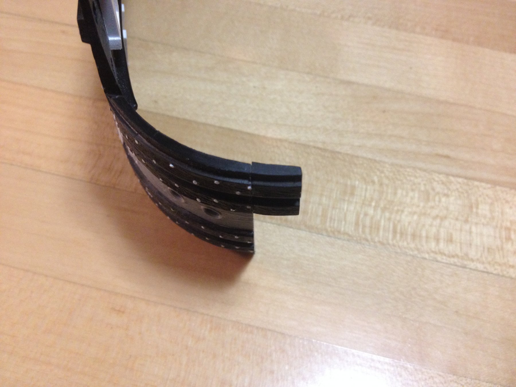
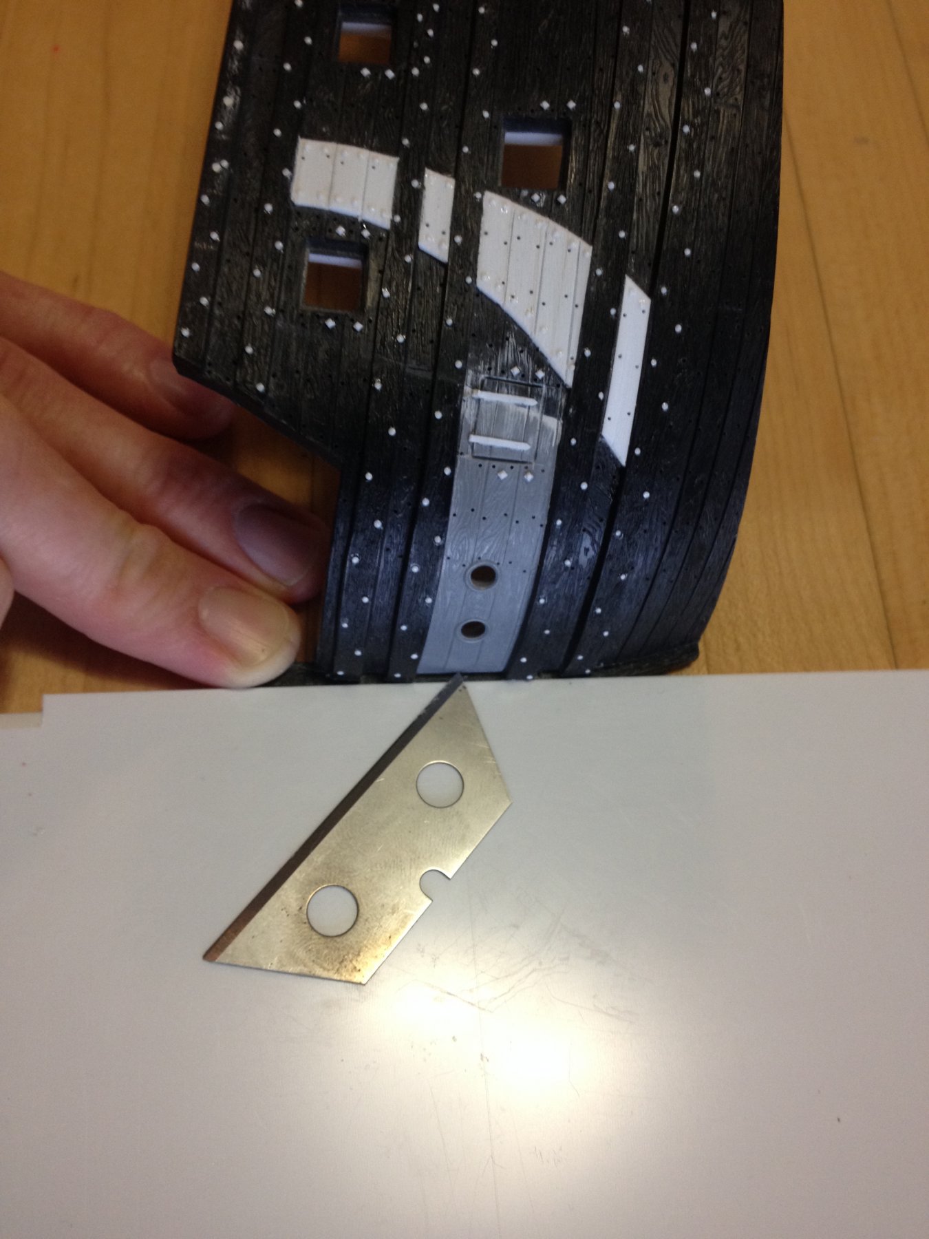
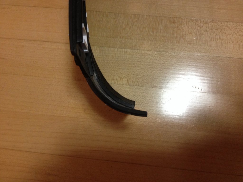
Well, a little bit of a rough start. I used the thinnest coping saw I own; blade thickness is less than a 1/32". However, the cut was a little difficult to control, as minute twists of the saw handle end up re-directing the blade. I'm sure that I sanded back a generous 1/16" to fair back these faces, but I have made allowance for that, so it should be fine. I think the angle of the mating face is very close to what it needs to be, however, I will make fine adjustments only when I have the mating extension pieces in hand. To scribe a cut line within a 1/32" of and parallel to the stem, I stacked sheet styrene with the stem flat against the table and then scribed a line with a single-edged carpet blade. Then it was a test of my hand-steadiness with a coping saw, which could have been better. Fairly terrible, actually. A large, flat sanding block, a reliable straight edge, and patient checking and re-checking straigtenned things out pretty nicely. Even if, in the end, I don't end up with the generous 1/2" width extension I am aiming for, at the bow, there is plenty of flexibility to set the aft edges where I need them on the model's new base-plate. After the extension pieces are glued in place, I will fill the old hawse holes and re-drill them back closer to the stem. This will also afford me the opportunity to make better and more reslistic hawser bolsters beneath the hawse holes, themselves.


- 2,699 replies
-
- 7
-
-
- heller
- soleil royal
- (and 9 more)
-
Okay, so the stern extensions are fixed in place, puttied to level any irregularities, re-enforced on their backside, and a uniform plank ledge has been cut into the aft edge of the hull. Not to sound too self-satisfied about it, but this worked about as well as I had hoped. I am encouraged, now, as I move toward the bow-widening pieces, which will involve carefully cutting away the stem piece from this model, so that I can glue in 5/16" extensions cut from Henry's model, before re-attaching the stem piece. laying out the cuts is critical, and maintaining a uniform cut angle, as I go, is essential so that I won't have to waste away too much plastic, in fairing the mating surfaces back together again. Possible, but tricky. I guess we've reached the point where I've just gotta say: "EFF it! Let's do this thing!!" Wish me luck. I'll keep you posted.

- 2,699 replies
-
- 8
-
-
- heller
- soleil royal
- (and 9 more)
-
What I wanted to say, essentially, was that one of the most enjoyable aspects of Dan's build logs are the annecdotal glimpses into the history of the ship that he often provides. In addition to that, Dan really scrutinizes the available photographic sources for useful details and it shines through in his work.
- 287 replies
-
- 5
-
-
- michelangelo
- ocean liner
- (and 1 more)
-
MONTAÑES by Amalio
Hubac's Historian replied to Amalio's topic in - Build logs for subjects built 1751 - 1800
Hello Amalio, These interior shots are incredible. Everything is so crisp and the joinery is superb. I am not very familiar with Spanish ships of this period and am curious about the shape of the rudder; it is so different from the practice of other European nations. Was there a handling advantage with this type of rudder? -
"So passes the glory of the world" Well said, Dan. And never more true. There's more that I would like to say about the Michelangelo and your build-log, but I will do so tomorrow. All good things!
- 287 replies
-
- 3
-
-
- michelangelo
- ocean liner
- (and 1 more)
-
MONTAÑES by Amalio
Hubac's Historian replied to Amalio's topic in - Build logs for subjects built 1751 - 1800
Hello Amalio! I am just discovering your build log. As all others have commented before me, your work is, at once, astounding, enlightenning, and completely spell-binding. You are a person of numerous talents with an un-failing eye for clean and fair lines. I'll be watching this one with great interest. So nice to see a Spanish ship, for a change! -
Thank you, Dan. I am with you on the flare, but it's just one of those inherent defects of the kit that aren't worth fixing. My hope is that the quarter pieces that support the side lanterns will draw the eye away from this detail, so that it isn't very noticeable unless you're really looking for it.
- 2,699 replies
-
- 2
-
-
- heller
- soleil royal
- (and 9 more)
-
Thank you, Cedric! And thank you to everyone for your likes, comments or just stopping by. It is all very encouraging and much appreciated. I intend to follow the lead of Dafi, and his excellent Heller Victory build-log, in which he greatly improved the realism and appearance of his transom windows by very patiently filing the mullions to about half their moulded thickness. Again, it's time consuming, but the results will never turn the effort expended into regret. For anyone who hasn't visited Dafi's log, I highly recommend that they do so. He is an enormously resourceful modeler, committed to his process, the results are extremely highly detailed, the work is truly impeccable, and his quirky humor and sensibility make for an excellent and entertaining read.
- 2,699 replies
-
- 2
-
-
- heller
- soleil royal
- (and 9 more)
-
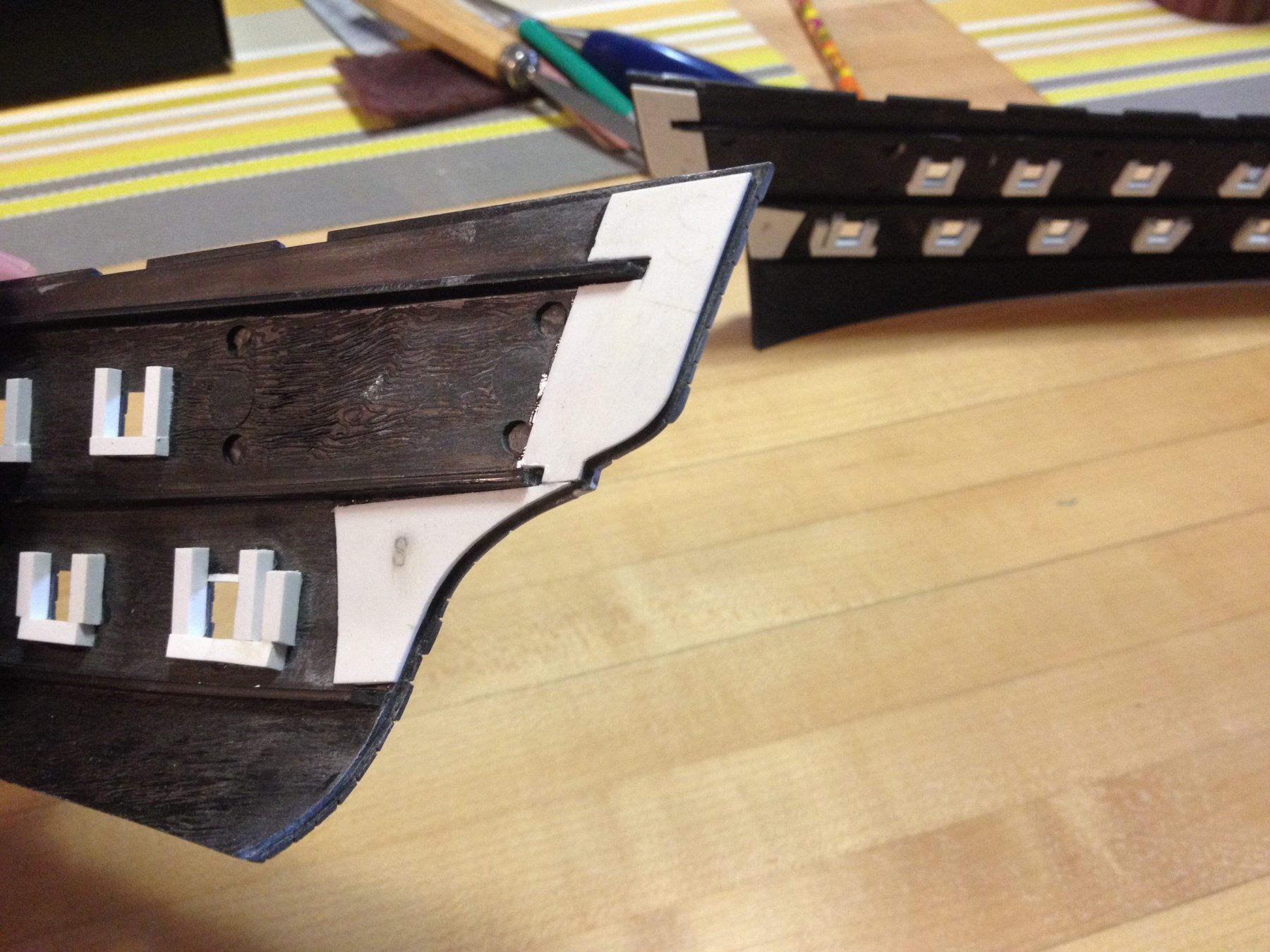
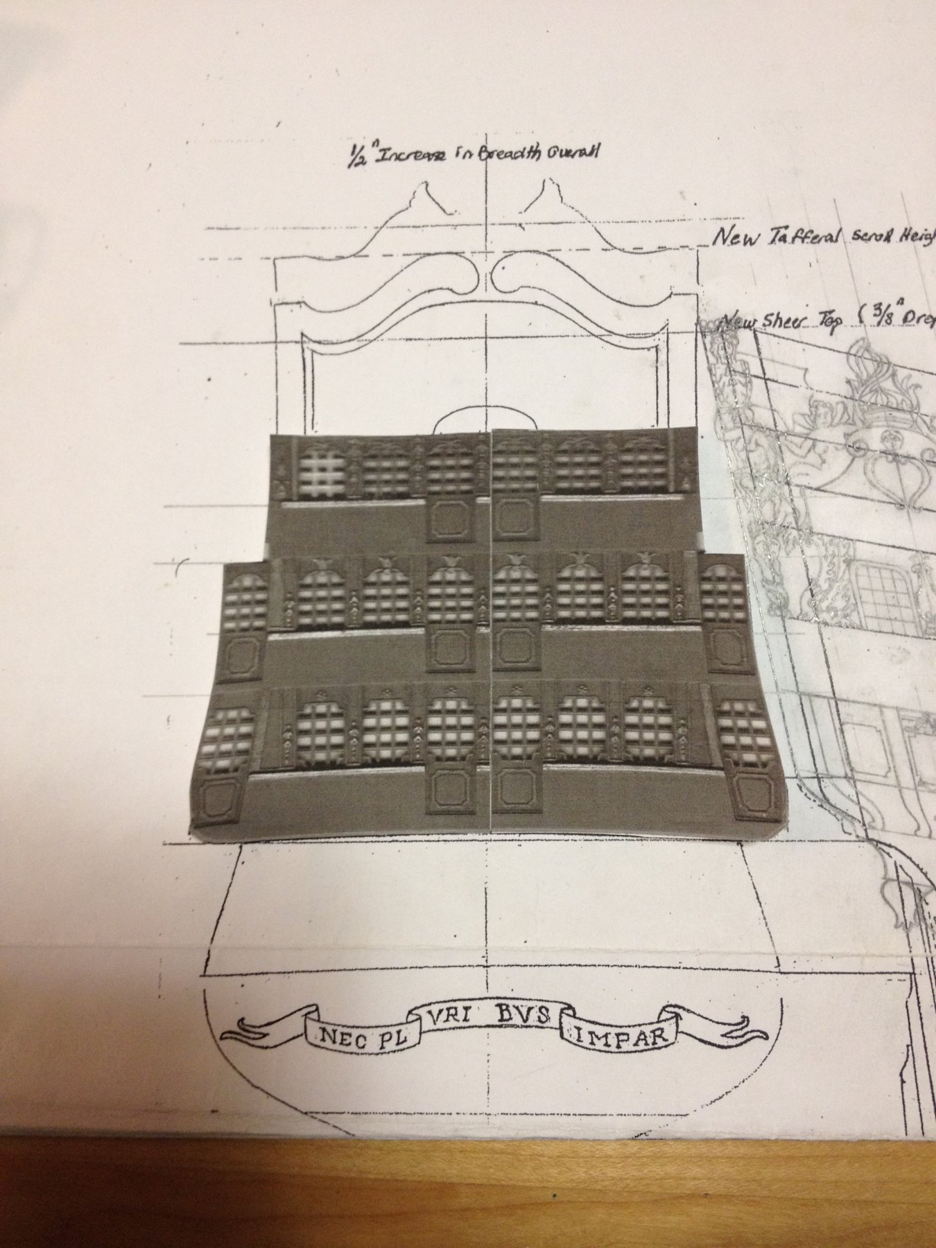
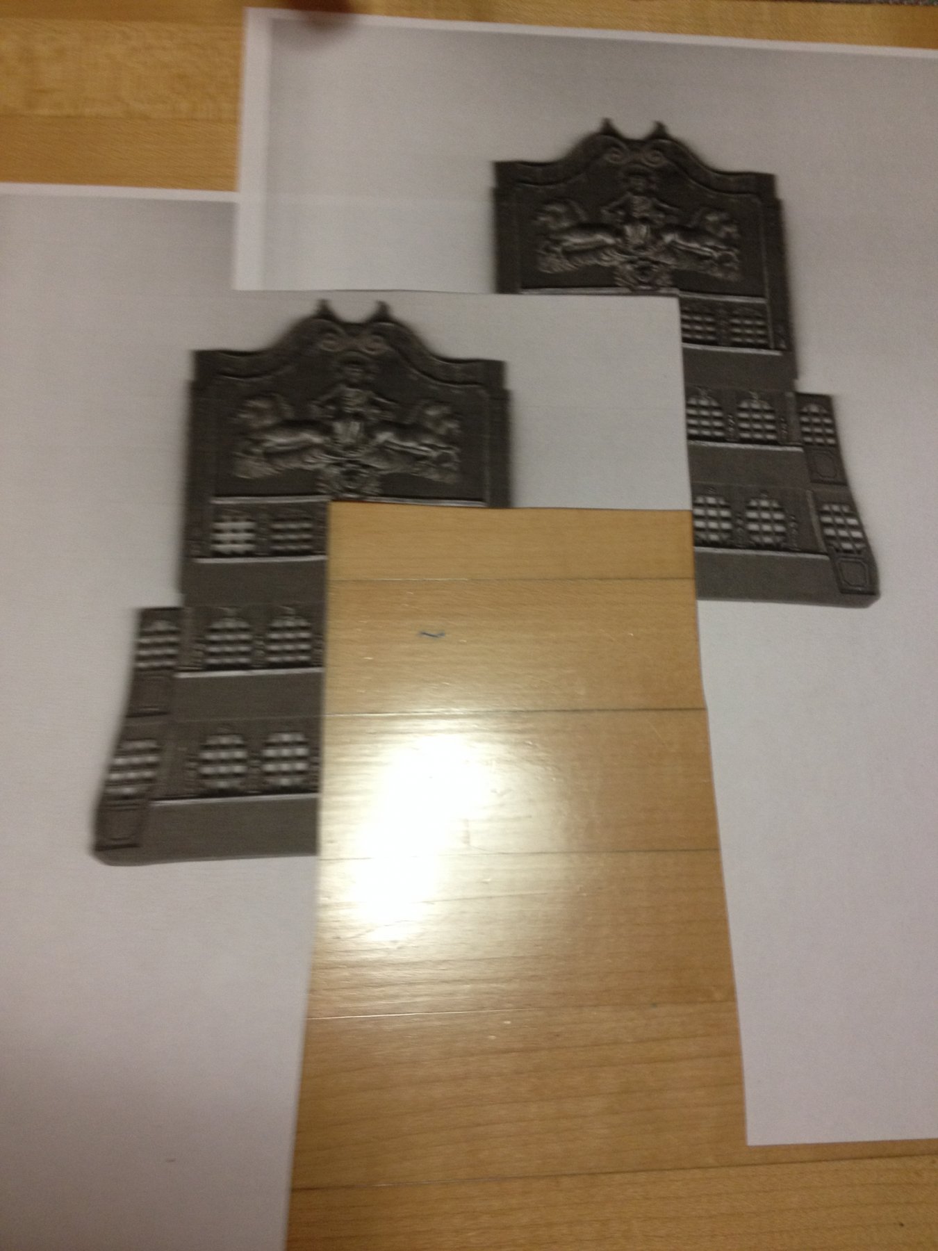
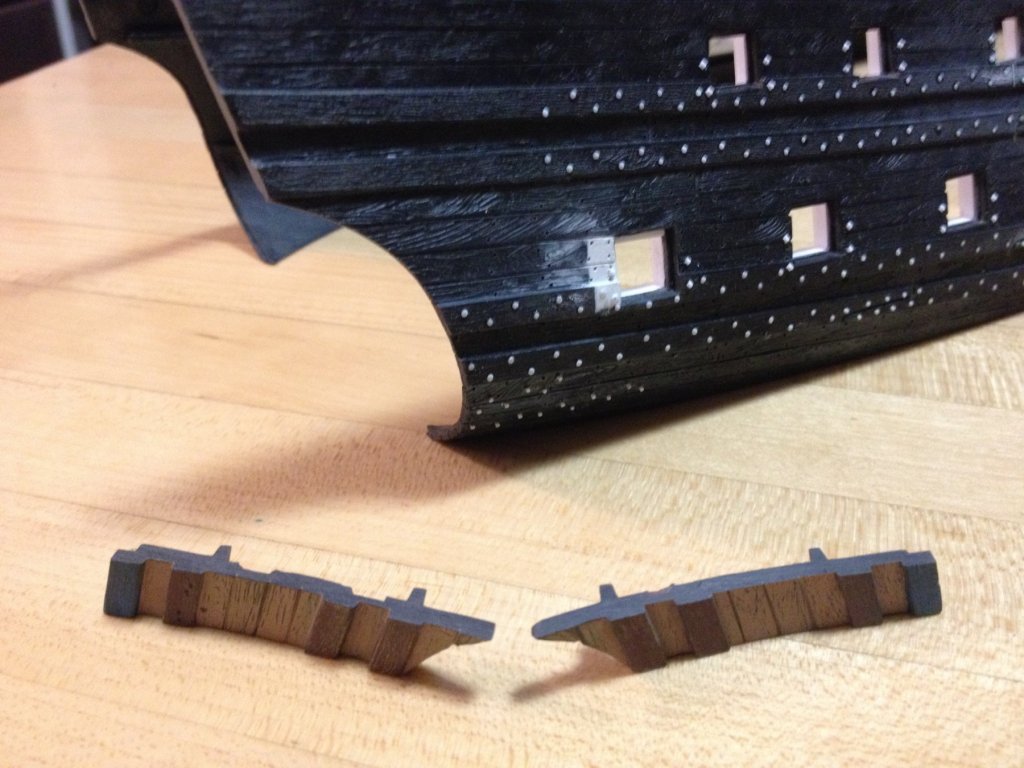
I've finished making the backing cleats for the stern extension pieces, and I've glued them onto the extensions, themselves. One difficulty of thinning the aft edge of the extension pieces - as was the case for the lower hull halves - is that it is difficult to control depth of cut in two directions. The result is that, while I can guarantee a consistent plank thickness for my plank butts, I cannot simultaneously create a perfect ledge for gluing the transom plank ends to. On straight runs, I could do both, but the arcs of the lower and upper counter were difficult to gauge. I decided to kill two birds with one stone by making my joint-re-enforcement backer, also my plank ledge, which is set back from the aft edge of the stern extensions by the same thickness as the styrene strip that I will plank with. The notches you see are to accommodate the existing deck ledges for the middle and main decks. Depending upon how I decide to deck the model (it will be with actual wood strip or scribed sheet), these deck ledges may have to be lowered, or reduced. Back here, at the stern, the location of the last quarter inch does not affect anything important, so I decided to scribe around their existing location. These backers will make for a sturdy joint without altering the run of the hull in any way. A little time consuming, but I consider it time well spent. Following that, I could not resist a simple experiment to see whether my idea to widen the stern by the missing 6th stern window would work. As you know, Henry (Popeye2Sea) sent me an additional stern plate from an old kit that was defective. The whole build and modification of the stern revolves around widening the hull to accommodate this missing window. The easiest thing to do was to make two photocopies of the stern plate, and then cut out three windows from one copy and three windows from the other - including the central access doors on both, and a missing pilaster on one. Although it is certainly arguable that a home photocopier is not the most reliable reproducer, at scale, I was very pleased to see how neatly these cutouts fit within the parameters of my drawing. The camber of the windows is not disturbed by adding the 6th window. I may yet keep the double access doors on the middle and upper balconies, but they will have to disappear altogether on the lower level because this will no longer be an open stern balcony; thus the creation of the stern extension pieces, in the first place. I'm sure that I will also be able to use the 7th and 8th windows, from the lower level, in my quarter galleries. I won't need the outer windows, though, from the middle and upper tiers. The plan is to carefully cut out the tiers of windows, and then heat bend them (with a curling iron, perhaps, or heated sand) to follow the new round-up of the framed stern. Fortunately, I will have plenty of spare window frames with which to experiment with heat, so that I don't make a molten mess of my project. I will then glue the three tiers of windows in place, along with their access doors, and then plank in between them with styrene strip. The time savings this affords me - to be able to recycle the beautifully detailed Heller window frames - is enormous, and frees me to concentrate my artistic efforts into other aspects of the build that can't be kit-bashed, like the shortened tafferal carving of Apollo and his horse-drawn chariot, or the altered cyma curve of the tafferal, below the figures of Europe and Asia.


- 2,699 replies
-
- 7
-
-
- heller
- soleil royal
- (and 9 more)
-
Your cathead support looks very good, Michel. I like the textured surface in the middle-ground of the carving. It off-sets the beautifully carved acanthus leaves nicely. Are you using some kind of micro, rotary burr to acheive this?
-
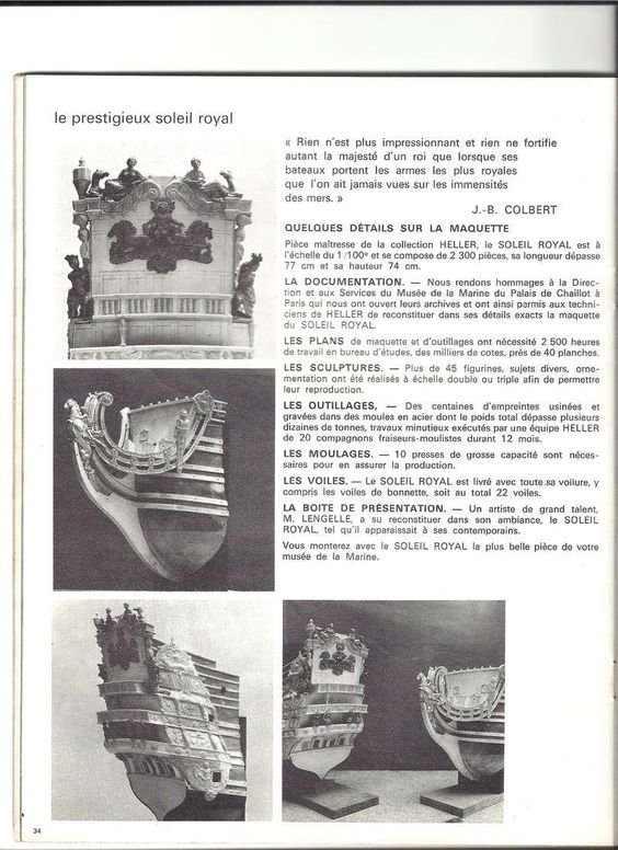
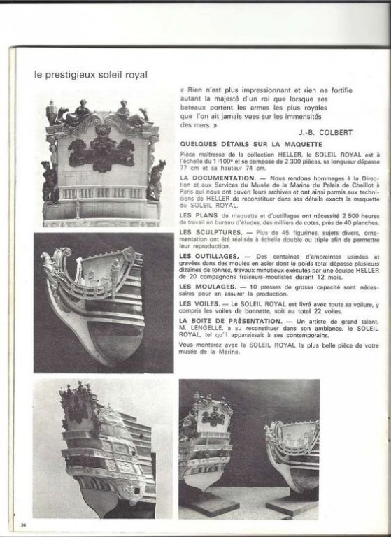
Surfing through Pinterest today, I found this highly fascinating screen shot from Heller's 1974 catalogue, in which, they introduce the Soleil Royal kit, and outline a bit of what was involved in it's development. Imperfect though it may be, Heller did go to some lengths to fill in the blanks left by Tanneron. However, as anyone can well imagine - when it comes to a money making enterprise, one does have to draw the line somewhere. I still think it is the best kit of it's epoch. Anyway, I thought this was cool. ---- I'm still working on the stern extension pieces. I've thinned the aft edge and scribed in the plank butts. Next, I'll make a new mounting ledge for the transom/stern planking. Finally, I'll mount them to the hull. Pics to follow.
- 2,699 replies
-
- 1
-
-
- heller
- soleil royal
- (and 9 more)
-
I also think your finish work looks really good, but what I particularly like is the satin finish at the tops and mast heads, painted black. The finish really pops over the black and the quality of your finish prep becomes even more apparent. As I've said a number of times, Ken, your willingness to work and re-work various aspects of the build have resulted in a truly first-rate build. Ingenious block tumbler, by the way.
-
Ken, you are a man of many talents. That second image could be a contest winner! Love the photography! Oh, and the ship is pretty great too.
-
Tonight, I managed to shape the upper stern counter profile into the starboard stern extension piece. It took a little doing, and a lot of checking back to my digital drawing, but I was finally satisfied with the shape. Before fixing it in place, I will thin the back edge and scribe in the plank butts, as I did for the lower transom. Once the pieces are glued, I will re-enforce the back of the joint with sheet styrene and epoxy.
- 2,699 replies
-
- 6
-
-
- heller
- soleil royal
- (and 9 more)
-
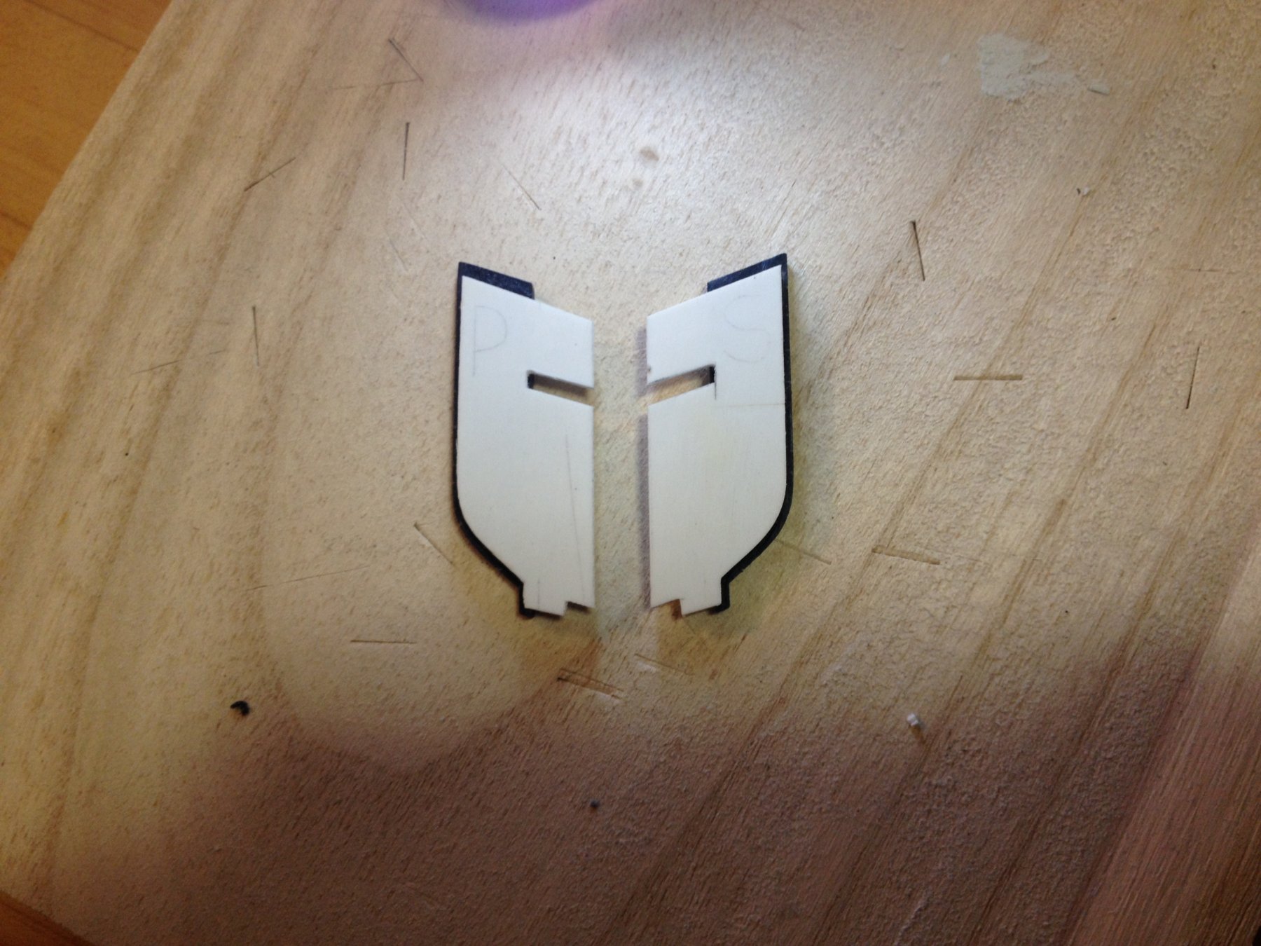
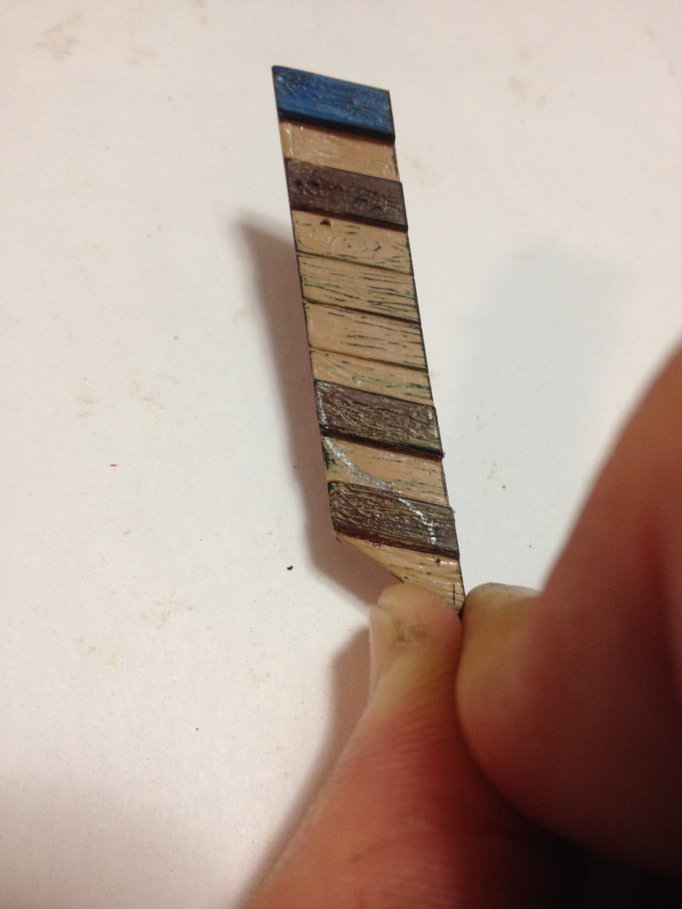
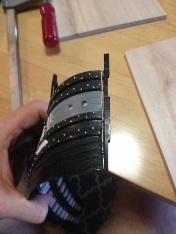
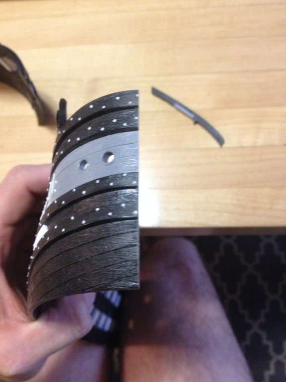
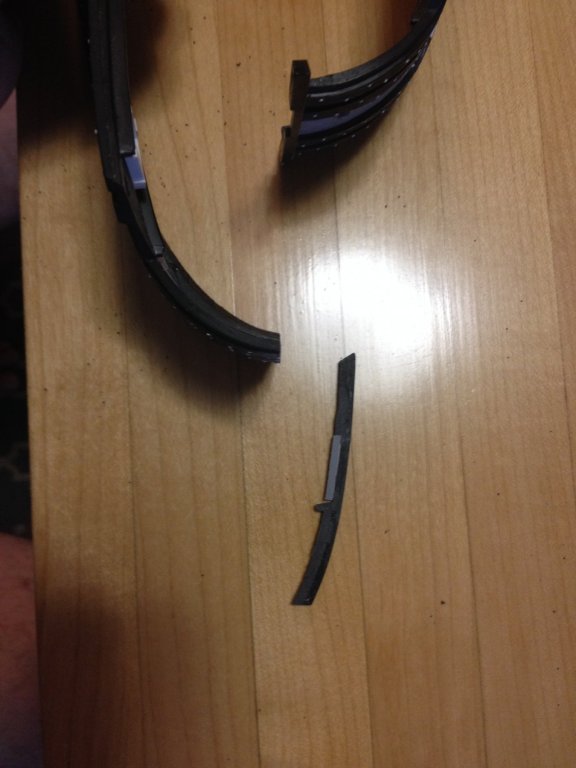
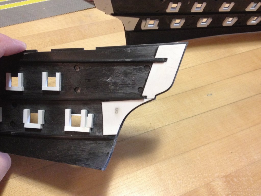
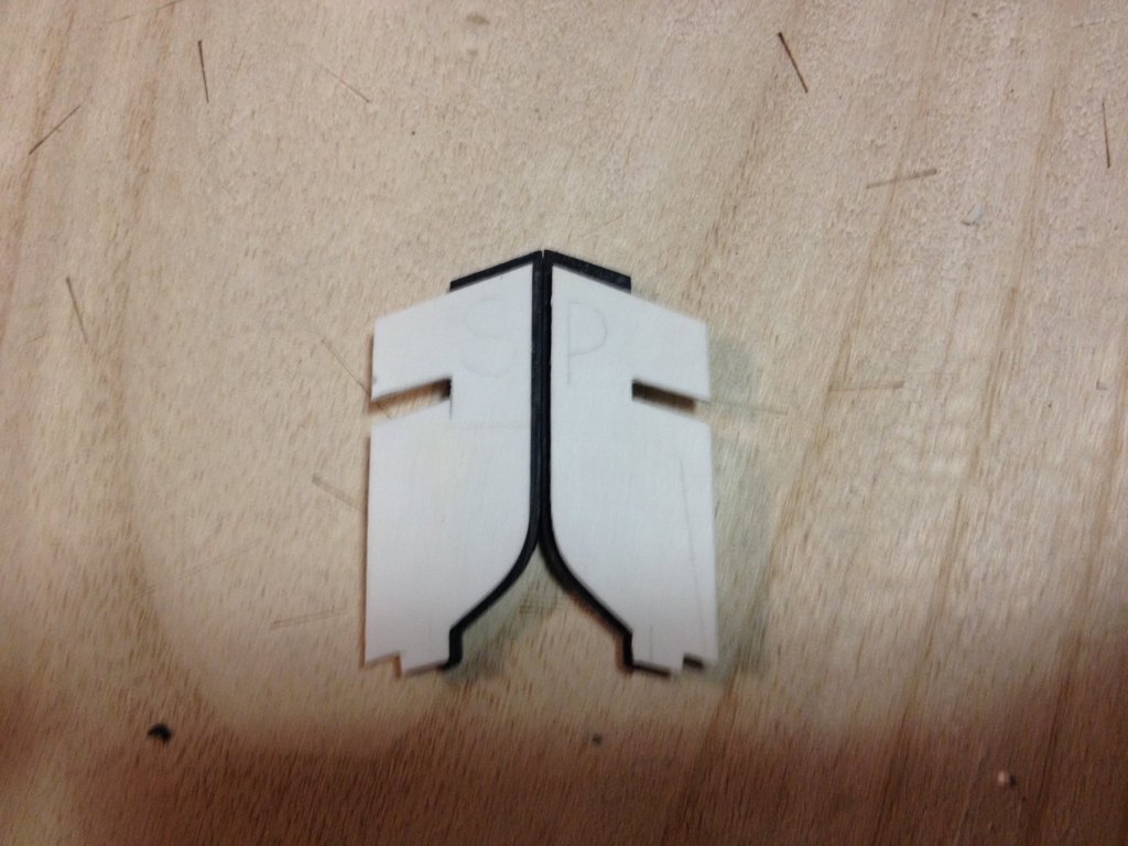
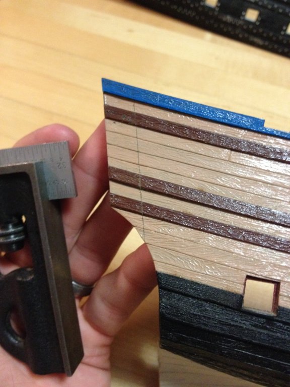
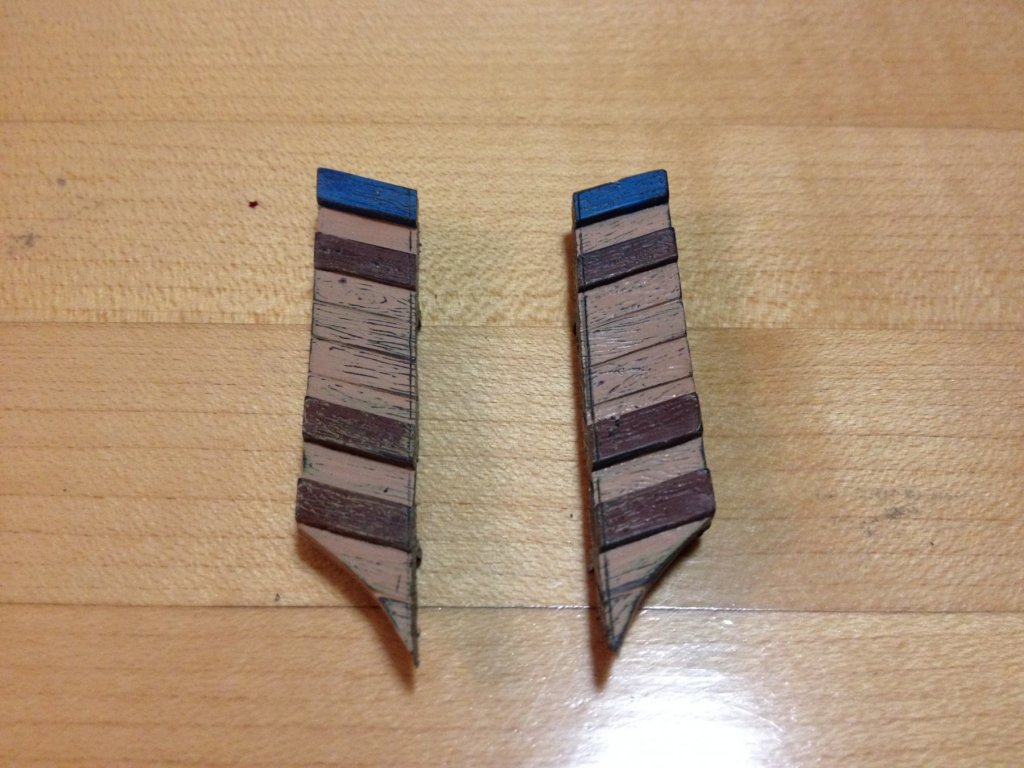
Having finally completed the drilling of the nail holes in the lower hull, I decided it was time to start tackling the first major modification of my kit-bash program. Rather than start with the widening of the bow, which presents a few tricky considerations, I thought I would first extend the stern by the 3/8" that I need to satisfactorily render Berain's quarter galleries, while simultaneously closing in the lower stern balcony, at the middle deck level. The first step was to true up the outboard edges of the hull, just above the counter. I did this on both the cut down hull that I am using, as well as the extra hull that Henry sent me: For the hull that I am using, it was essential to sand the edge straight and square because this will be the mounting surface for the extension piece. I applied the same care to Henry's hull, so that I could accurately mark out the 3/8" (+ an extra 1/64" for fitting loss) I needed with a try-square: Then, I used a really sharp coping saw to cut within a heavy 1/64" of my marked line. Here are the rough-cut blanks: Then, I sanded those faces to my line - offering up to the joint frequently, in order to be sure that the extension wasn't skewing inboard or outboard, but remaining true to the run of the hull. Here's a dry-fit extension piece: As I had hoped, the extension is short enough that the run of plank lines and wales remains continuous, without any tell-tale steps. Back here, it really won't matter as most of this will be completely covered by the quarter galleries, themselves, but this is encouraging for the bow. The repeat of moulded grain detail is negligable and hardly worth worrying about. The next step was to sketch in the new shape of the stern counter (which, previously would be an open, wrapping stern balcony on the stock kit). The reverse curve, here, is so subtle that it is difficult to draw on the uneven surface with any fidelity: Experience tells me, though, that I will have better success "drawing" with the tools. The pencil line, here, is merely a guide. I have decided, though, that I am too tired to give it the full focus that profiling requires, so I will postpone cutting these shapes until another night. The Dremel is out of juice, anyway.


- 2,699 replies
-
- 7
-
-
- heller
- soleil royal
- (and 9 more)
-
Thanks, Michel! The first two pages that I have read, so far, are certainly enlightenning.
- 2,699 replies
-
- 2
-
-
- heller
- soleil royal
- (and 9 more)