


gsdpic
-
Posts
843 -
Joined
-
Last visited
Content Type
Profiles
Forums
Gallery
Events
Everything posted by gsdpic
-
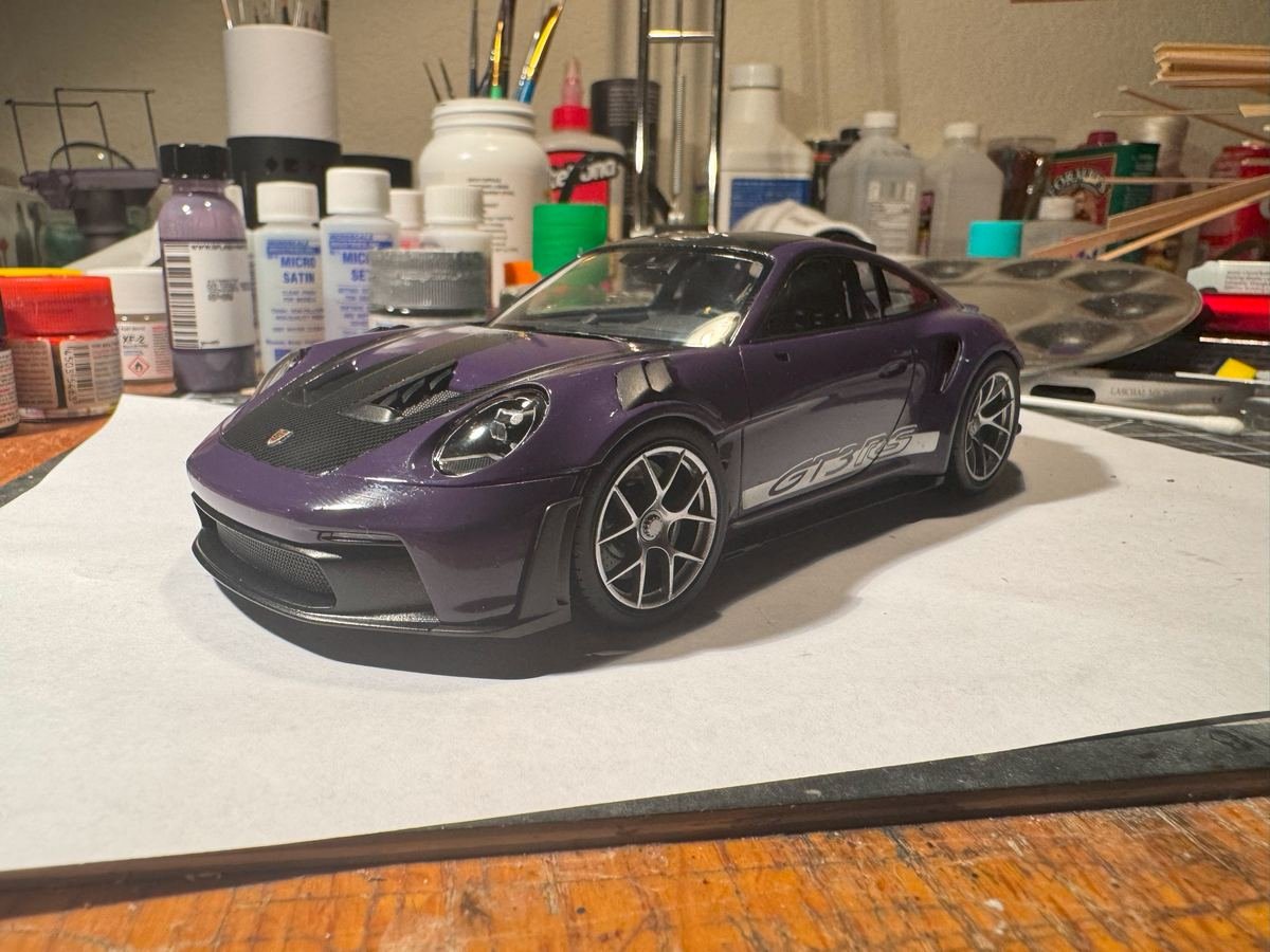
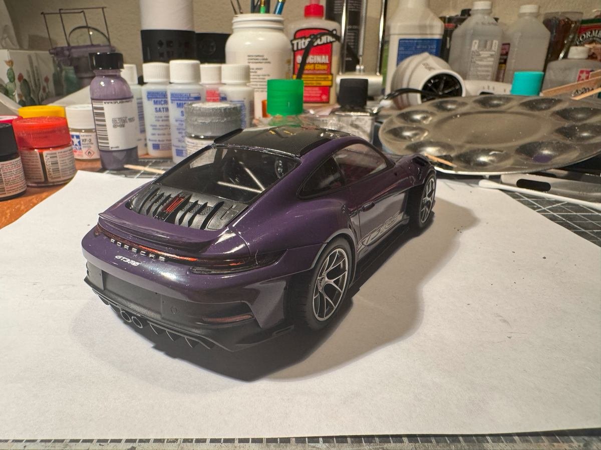
Thanks for the likes or just stopping by to take a look. She's now down on her own wheels and very lose to completion. Just need to do the mirrors, door handles, wing, and some air deflector thingies behind the wheel. Then try to do any clean up and touch up and take some better photos with the real camera and better lighting set up. One might think the rear view mirrors would be simple but no....each one is 4 pieces and 3 carbon fiber decals. The wing is a bit delicate too, though I have it mostly done.
-
Beautiful! I thought the kit wheels in the previous post looked pretty good but the after market ones are a significant improvement. I might need to get a set of those if I ever get around to building my 250 GTO.
-
Been working a bit more on the body bits but have continued to put off painting the windows. I need to tackle that soon.
-
CA (cyanoacrylate) "super glue"
gsdpic replied to Dr PR's topic in Modeling tools and Workshop Equipment
I've used the Loctite gel in the fancy applicator bottle to the end of the bottle. For me, the more likely failure is for the glue to take longer and longer to cure after opening the package, as the glue ages. Is Corvallis, Oregon particularly humid? Superglue cures by chemical reaction using moisture in the air. Maybe a particularly humid environment makes it more likely to harden before being used up. -
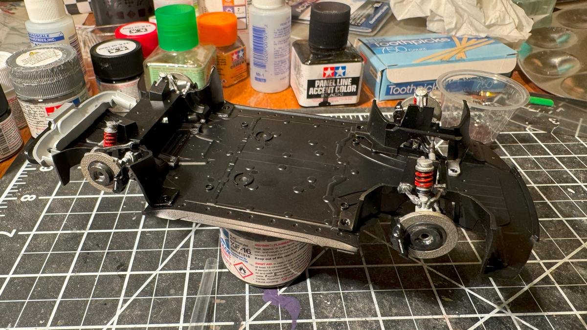
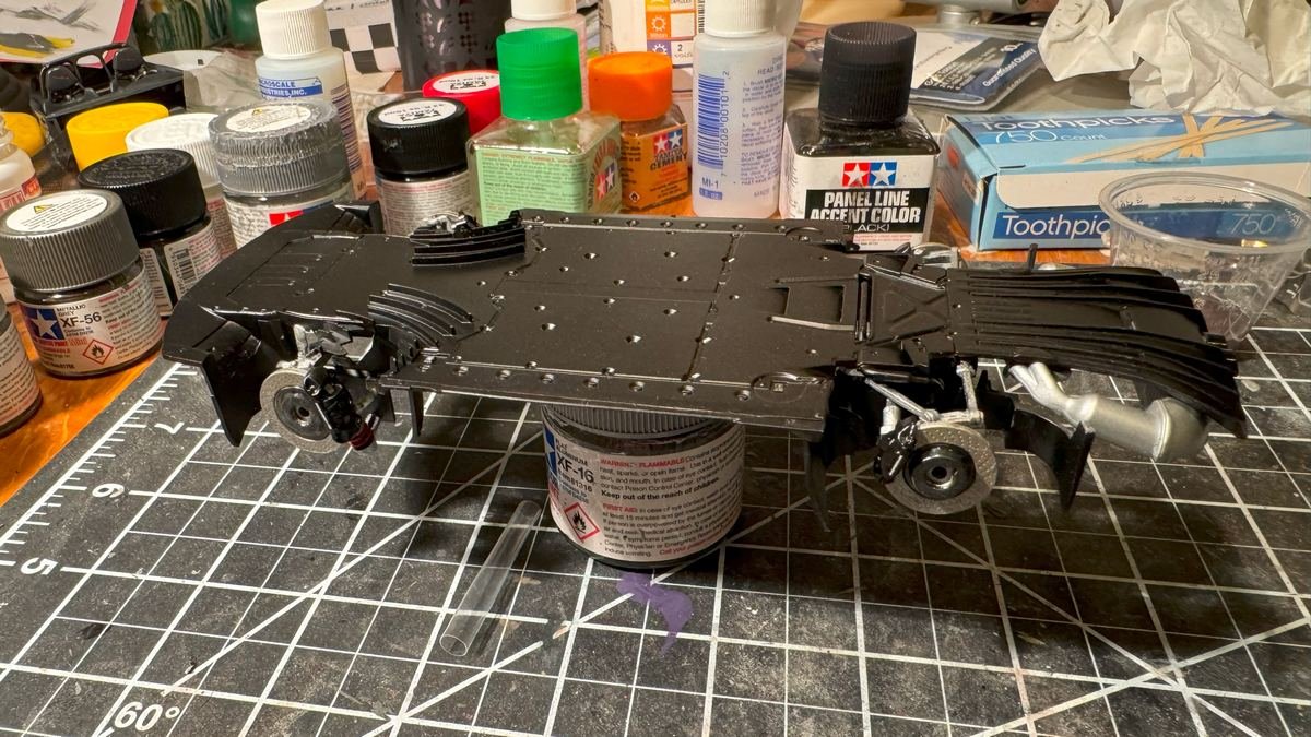
Thanks for the likes or for just looking in. I've now completed the chassis and put the interior on the chassis. From here on it is all about attaching all the bits to the body and then putting the two together. The trickiest remaining thing is probably masking and painting the windows, as both sides and front and back windows all have some black border to be painted. Other than the windows, I think I have all the painting done, except perhaps some minor details here and there. I added a few more coats of clear to the body and it is looking shinier but have not done any sort of polishing just yet.
-
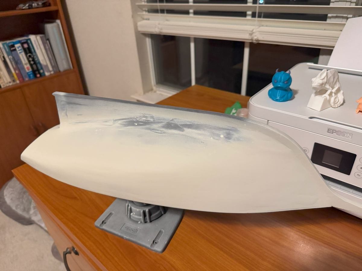
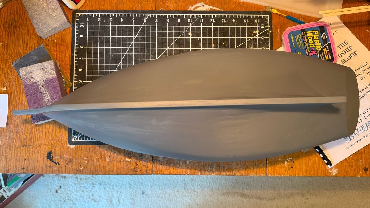
Ok, I sanded down the color coat (just once!) and repainted and it is looking good. Now to mark the waterline, tape it off, and paint the hull with the dark green paint. Haha....I see now some of the test prints from my recently acquired 3d printer in the background. I took this shot by my computer instead of in the modelling room.
- 90 replies
-
- 6
-

-
- Friendship Sloop
- bluejacket shipcrafters
- (and 1 more)
-
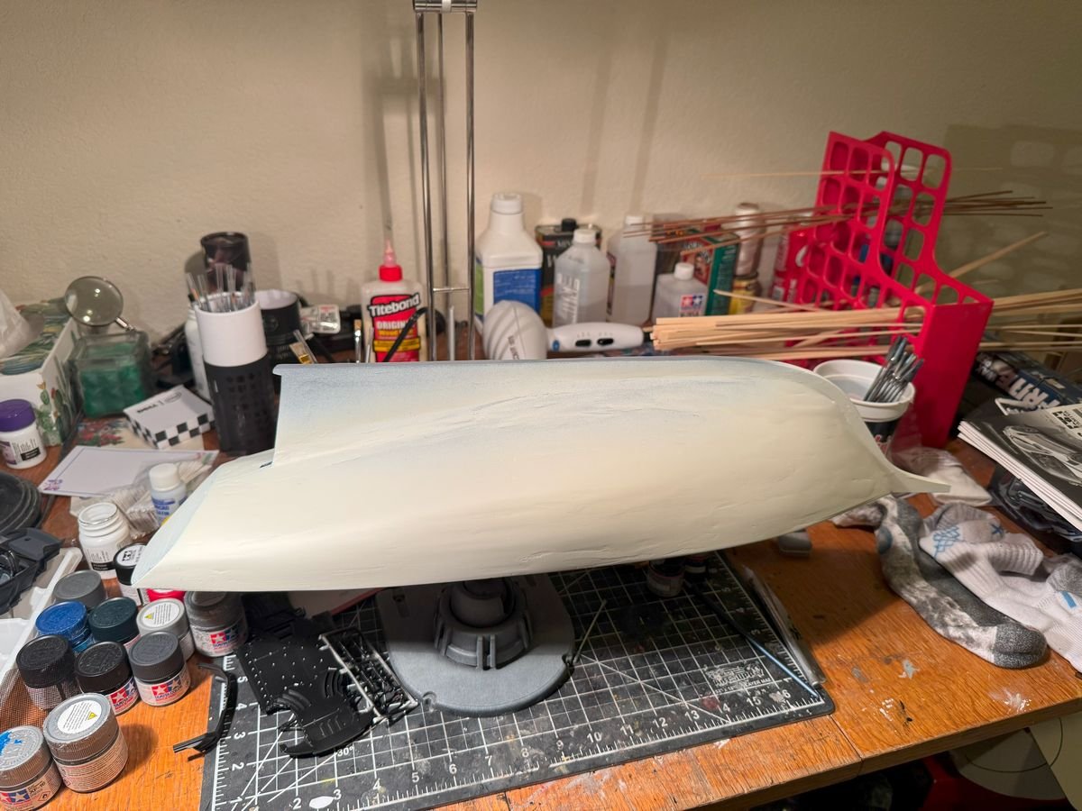
I wouldn't know a George Strait song if it slapped me in the face, but I can see why that song came to mind. Note that I did not say how many iterations of sanding and spraying I was going to do with the color coats. And speaking of that, I finally sprayed on the topsides off white color. The color is not quite as off white as I expected but it will do. And yes those flaws in the finish on the side do bother me a bit so I guess I am not done sanding. Once I am satisfied or tired of it, I'll tape off the water line and repeat with dark green below the water line.
- 90 replies
-
- 3
-
-
- Friendship Sloop
- bluejacket shipcrafters
- (and 1 more)
-
Very, very nice planking job. That does look like a bit of an odd and tricky shape at the stern.
-
Hi Barbara -- I have built the 1/48th scale Bluejacket America. See the link to the build log in my signature. Overall, I was pleased with the contents of the kit and the instructions. For the most part the instructions were adequate though there were places where you had to read between the lines/make stuff up to complete a step. But I did not hit any particular road blocks. But having said that, it is very much an older style kit that leaves a lot up to the builder. As I recall there are no laser cut parts. The keel and stem and stern post were preprinted on bass wood sheets but needed to be cut out. There is no "sub deck", instead you create deck beams that fit across the frames. It is definitely a kit for someone who has some experience and practice. The bluejacket skill level they assign to the kit is basically an 8 on a 9 point scale. Feel free to look at my build log and I hope that will give a good idea of what is involved in building the kit. I will say that it can be built up into a beautiful model.
-
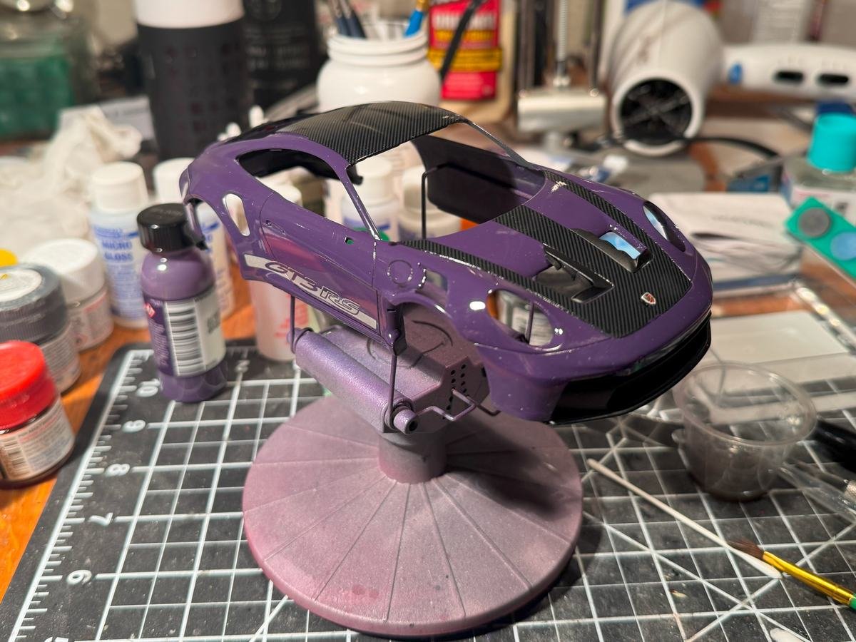
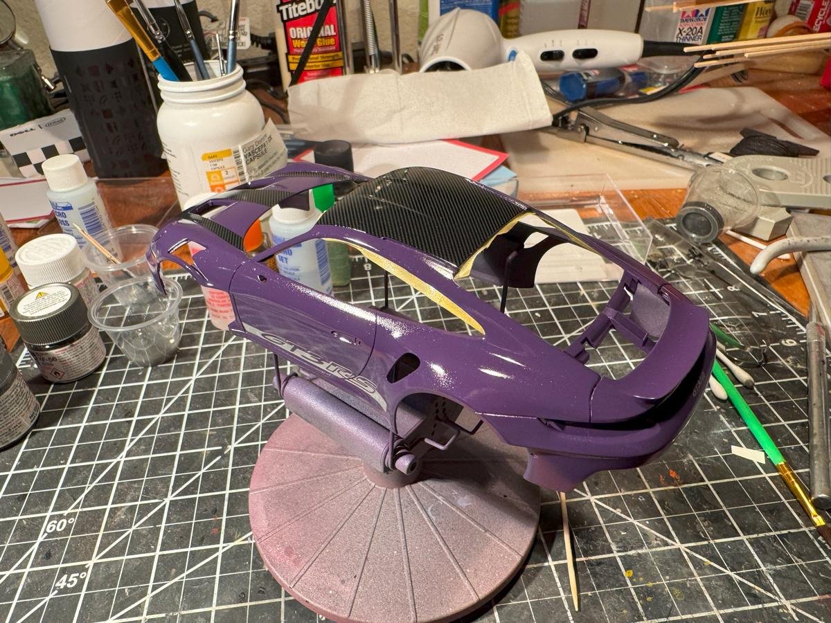
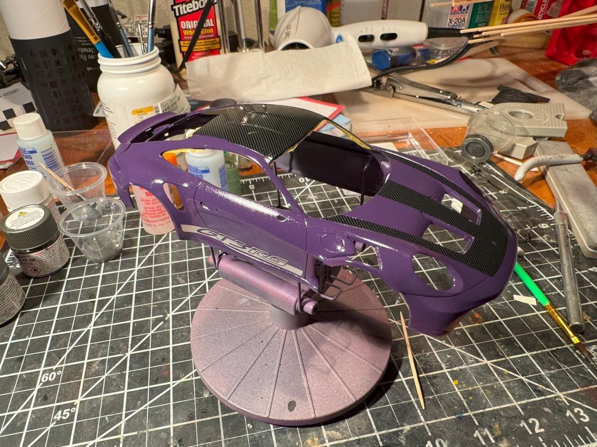
Thanks for looking in and hitting the like button. I guess it is time to reveal the exterior color, as I have made progress on that though not finished it. It is....ultraviolet. And yes this was a color available from Porsche on some of their GT3/GT2 models. As mentioned before, I got the paint from Splash paints. I then put on one coat of Tamiya X-22 thinned with Mr Color Leveling Thinner (about 50/50), then put the decals on, then put another thinned coat of X-22 on. I'll probably do another coat or two of the clear and also want to try some polishing as well to try to improve the finish. The bits of masking tape you see are protecting the headliner area which is the same German Gray as the interior. The rear spoiler piece and front nose piece are just temporarily tacked on using a couple dots of white glue.
-
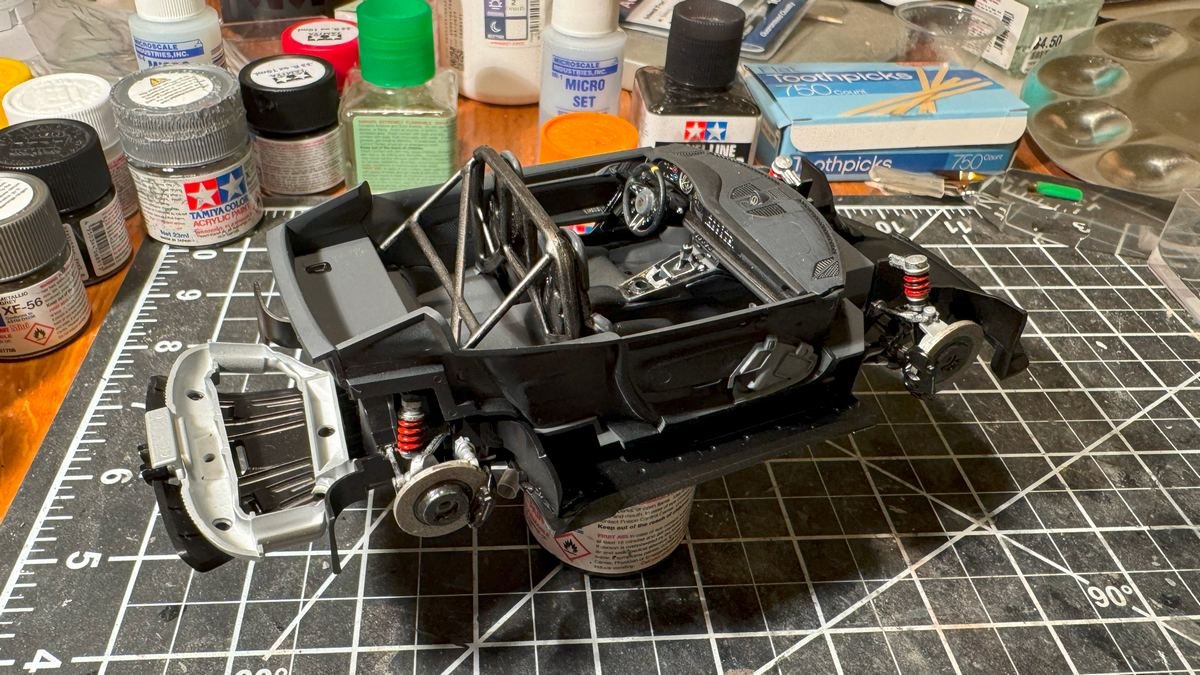
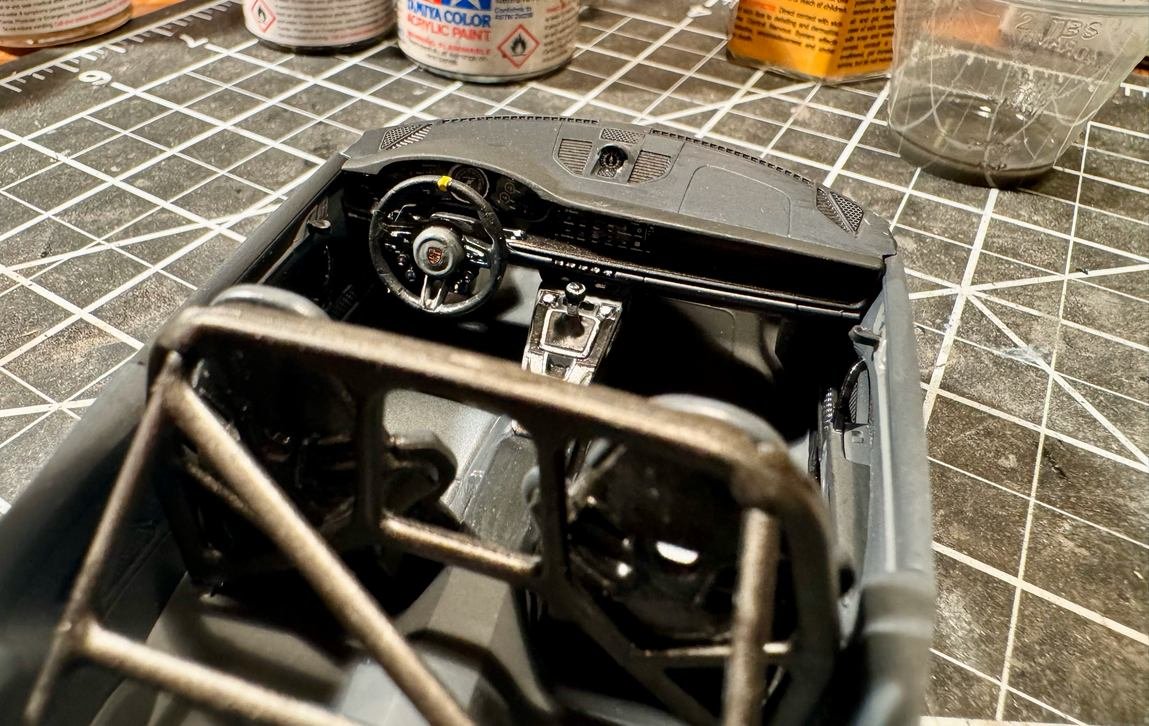
Thanks all for the likes. I am now done with the interior, steps 9-14 in the instructions. I plan to now go back to do the chassis, steps 1-8 while also working on the body clear coat and decals. Of course once installed in the body we'll never again have a good view of the interior.
-
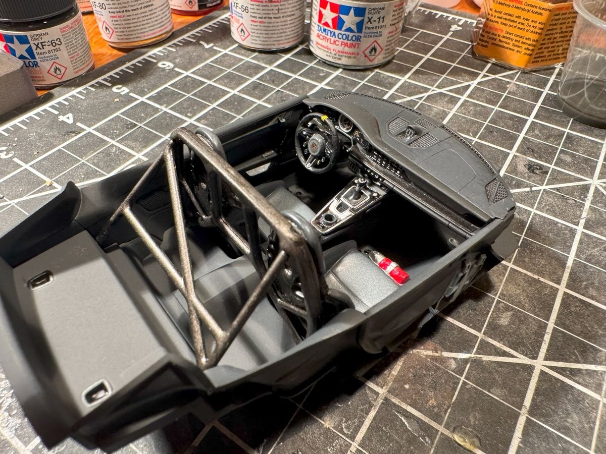
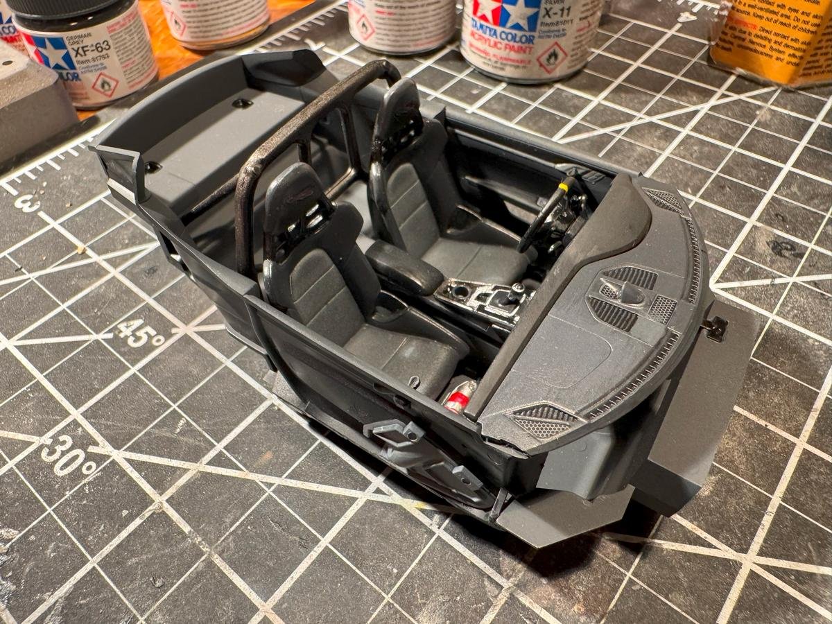
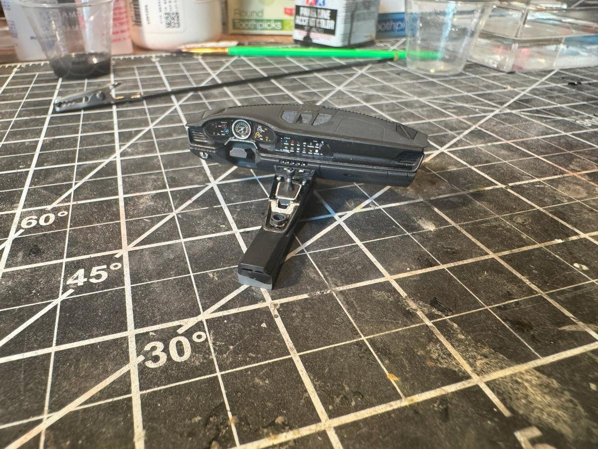
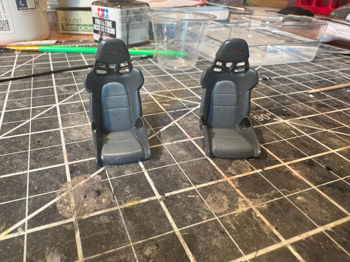
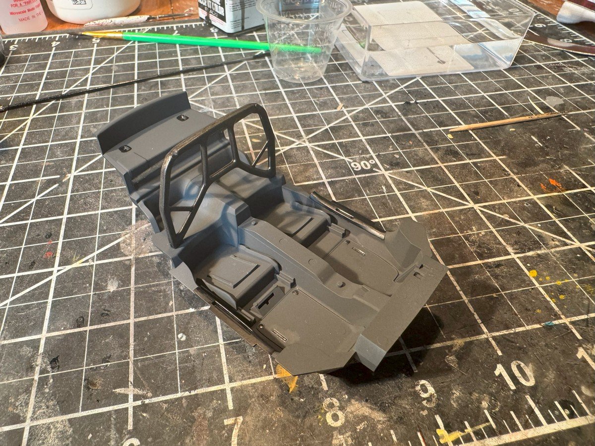
Thanks for the likes and for looking in. I've been doing some work on the interior, even though that is step 9 - 14 in the instructions. I started out using "German Gray" as the base. That seemed appropriate for a Porsche. I wanted gray instead of black just to make it hide details less. Here's the basic tub with the roll bar. The roll bar on the prototype has a carbon fiber finish, and there is some carbon fiber on the seats. I used a mixture of black and metallic gray to attempt a carbon fiber look. The seats: And finally the dash and center console: I still have some detailing to do on the door panels and the steering wheel, and a few parts....fire extinguisher and pedals...on the main tub, then I'll put it all together. I've also painted the body the yet-to-be-revealed mystery color but have not started doing any clear coating or applying decals to the body. I started on the interior first because I also painted the inside of the body (headliner area) with the same German Gray. I wanted to do that before painting the exterior and so figured I might as well work on the interior.
-
Ok, one more round of sanding and priming. I swear I am done this time. I'll let it cure a day or two then do some light sanding, draw a waterline, and add some color. I bought two more rattle cans of paint....and off white for the top sides and a dark green for the bottom of the hull.
- 90 replies
-
- 6
-
-
- Friendship Sloop
- bluejacket shipcrafters
- (and 1 more)
-
It looks basically the same as a product offered by "The Small Shop". https://thesmallshop.com/ Unfortunately I believe they have ceased or at least paused operation. The web site is still there but everything shows as "sold out". In the past I think I saw a note there that they were stopping, though I don't see that on the web site now.
-
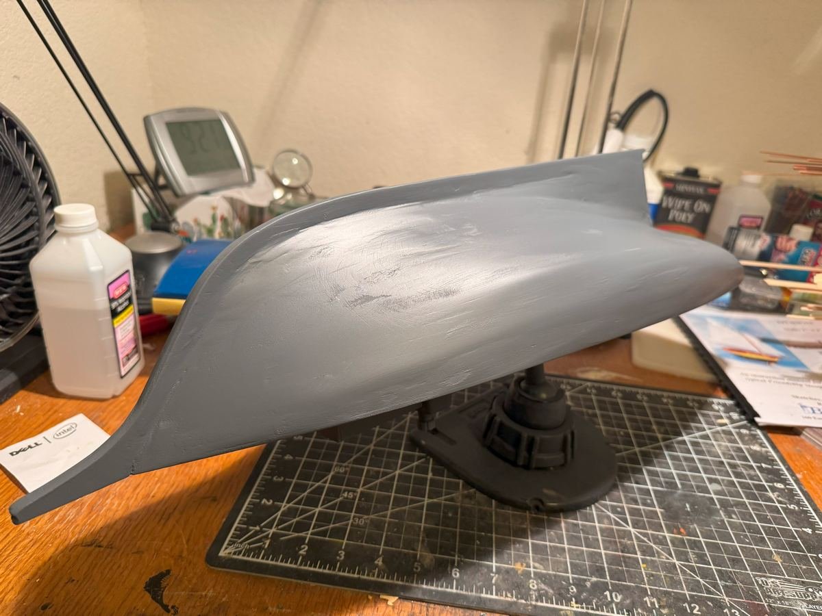
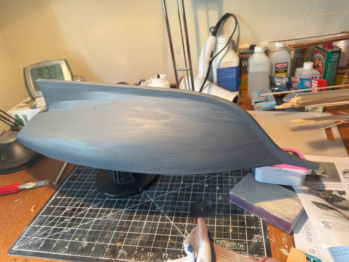
I've done more sanding and yet another coat of primer. It is still far from perfect but getting better, and of course without the bright lights the imperfections are less noticeable. I will also say I do not recommend that wood filler I have been using. It seems difficult to get a good smooth finish with it, and somehow it seems inconsistent when you sand it....sometimes it sands off easily other times the edges continue to show even after sanding. This latest coat of primer is still curing; I'll probably decide tomorrow if I am going to work it more or say it is good enough.
- 90 replies
-
- 3
-
-
- Friendship Sloop
- bluejacket shipcrafters
- (and 1 more)
-
I've sprayed some of the splash paints primer on the body and on all the parts while still connected to the sprues. I admit I was not super diligent about getting perfect coverage of the latter. There are certain colors, like semi-gloss black, that are used on a lot of parts. I'll probably separate those from the sprues and start painting them, and also start painting the body and related parts as well. I think I will use a medium-dark gray for the interior, rather than black, just to try to allow the details a little bit more visible.
-
As others have said, congrats on the well deserved medals. After the raffle haul, did you buy a lottery ticket on the way home?
-
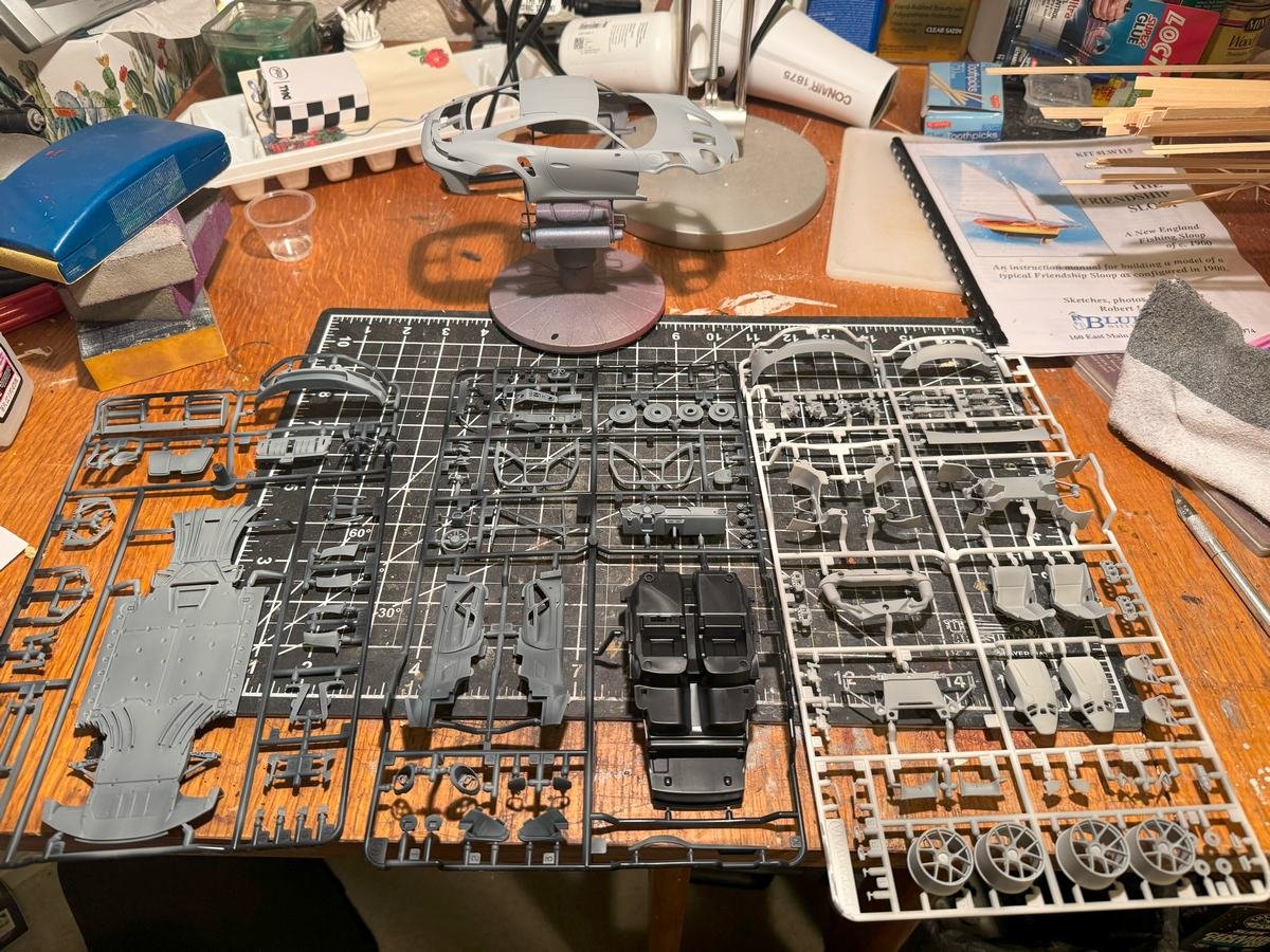
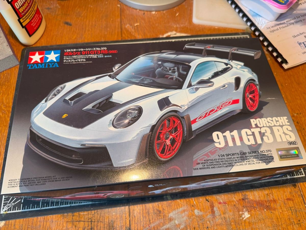
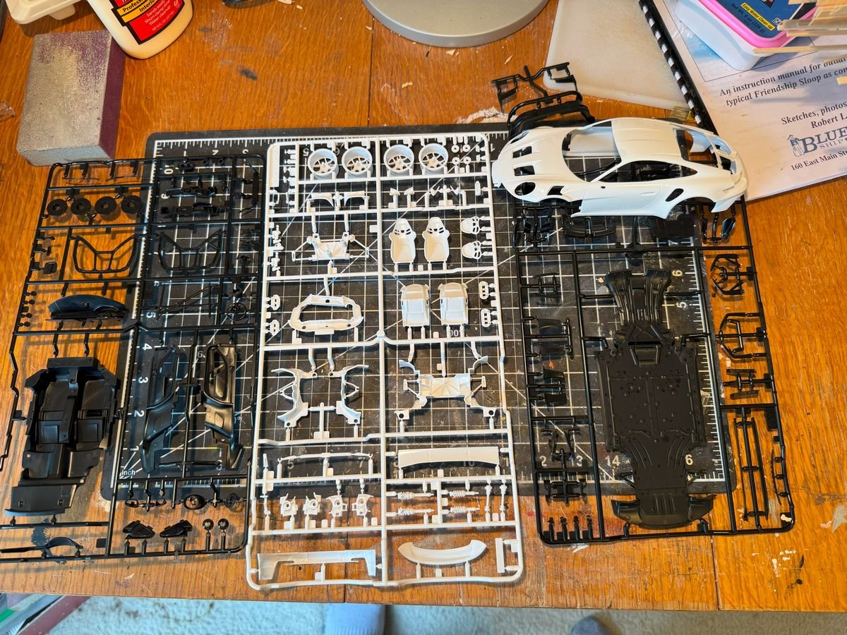
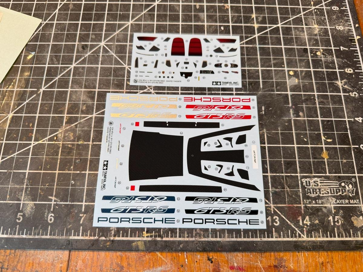
Welcome to my build log for the 2022 Porsche 911 GT3 RS by Tamiya. I just can't help myself. I've been working on the Bluejacket Friendship Sloop and swore I would not start another project while working on that. But here we are. I kept looking at my ever growing stash of plastic cars and could not resist. I've included pictures of the box and most of the kit contents. There is no replication of the engine, but there are plenty of details in the body and interior to add some complexity. The engine would not really be visible anyway. As usual, painting will likely consume most of the construction time. The decals are nice and include four different colors of the GT3 RS logo that goes on the side....blue, black, silver, and red (in the picture the blue and black look almost the same and the silver looks more like gold). Overall the kit appears to be typical Tamiya high quality. Interestingly, there are no plated/chrome parts, which is just as well. The one area that I noticed that is perhaps a bit sloppy is the strange paint recommendations in the instructions. They recommend a combination of the Tamiya lacquer (LP) paints and Tamiya acrylic (X or XF) paints. In some cases, they even have the same color of both types....e.g. some parts are indicated as LP-5 Semi gloss black while other parts are indicated as X-18 Semi gloss black, with no rhyme or reason that I have determined. Also, some of the paint colors called out do not appear in the list of paints on the first page. e.g. it indicates the brake calipers can be painted LP-21 Italian Red though that color is not listed on the first page, while X-7 Red is listed. Speaking of paint....one nice thing about modeling contemporary Porsches is the "paint to sample" program they have. For a little bit of spare change (err...$20k for the GT3 RS) they will let you pick from a large library of colors that have been used by Porsche over the years. Double that amount and they will work with you on any color you want. So, I can paint this car any color and still claim that it could be realistic. Without too much thought or hesitation, I knew what Porsche color I wanted to use and was glad to see that it is one stocked by Splash paints. I think I'll let it be a surprise. As stated, I am also working on the Friendship Sloop so I am not quite sure how my progress will go on this. I'll likely work on one when paint is drying on the other.
-
Primer coat number 3. I am going to resist the urge to use any more filler and just sand this down a bit and do one more coat of primer, once this coat cures a bit more. There is one place where I have just about sanded through the planking but I have access to that part of the inside of the hull so I can put in some reinforcements.
- 90 replies
-
- 5
-
-
- Friendship Sloop
- bluejacket shipcrafters
- (and 1 more)
-
That's an interesting looking car. I am sure you'll turn it into a stunning model. Looking forward to following along and learning more of the quirks of building MFH models while I work up the nerve to start on one of my two MFH kits.
-
Looks great! Such an elegant little craft. And yea I remember also having trouble taking pictures of it due to the extreme proportions.
- 47 replies
-
- 4
-
-

-
- Annapolis Wherry
- Chesapeake Light Craft
- (and 1 more)
-
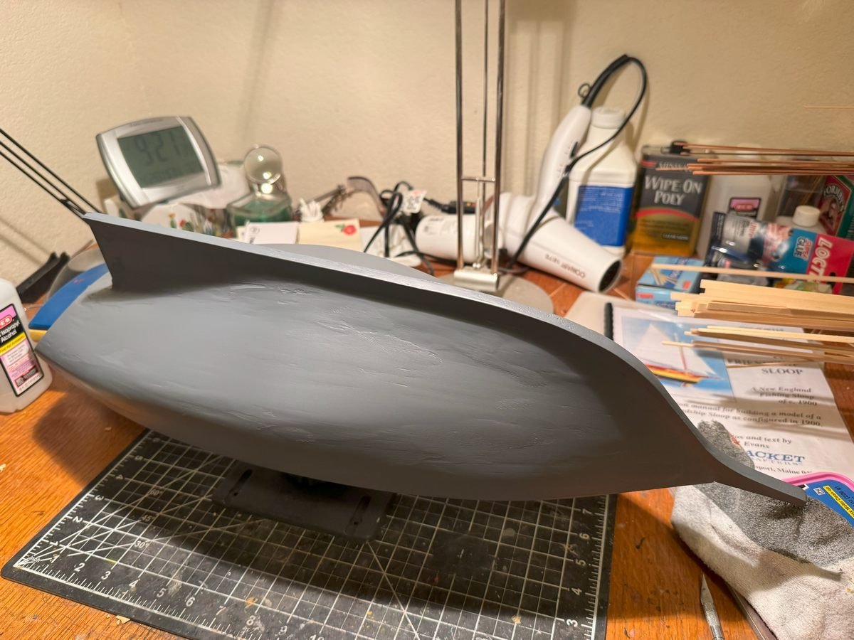
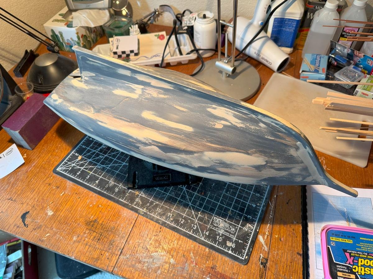
Thanks for taking a look and hitting the like button. I've applied the next coat of primer and I also patched up that little hole between the stern post and transom. Obviously I need to do more filling and sanding around there once the glue dries. Looks like I still have a few small spots elsewhere on the hull that I want to add some filler to, and then another round of sanding and priming. So far I've just used 120 and 320 to sand it. I think this time I'll go to a higher grit and try to get down to a final smoothness, then one last (I hope) coat of primer). I am still thinking white or off white top sides and green or greenish blue hull but I have not settled on anything 100%. I am almost ready for that but should determine what other parts, like the rudder and rudder post, should be painted at the same time. And pay no attention to the clock in the background, I obviously don't. I took those first two pictures around 9am on April 24, not last Friday night 😆
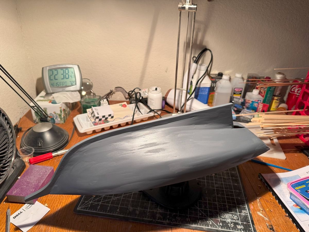
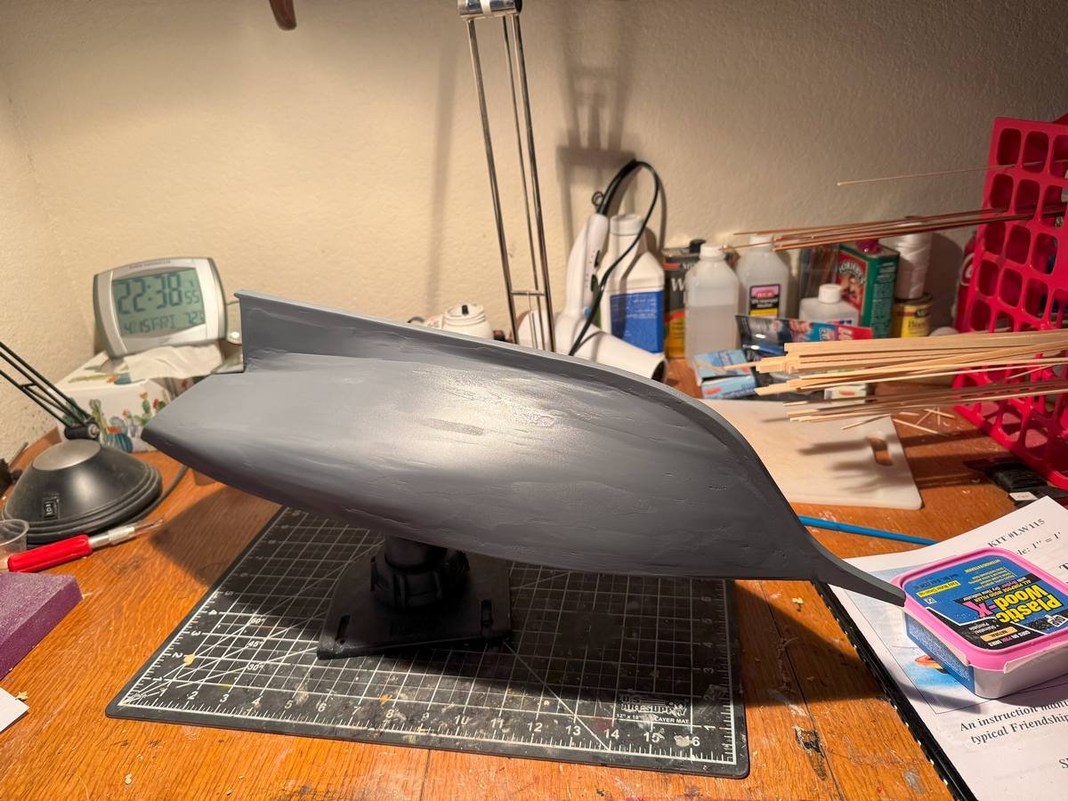
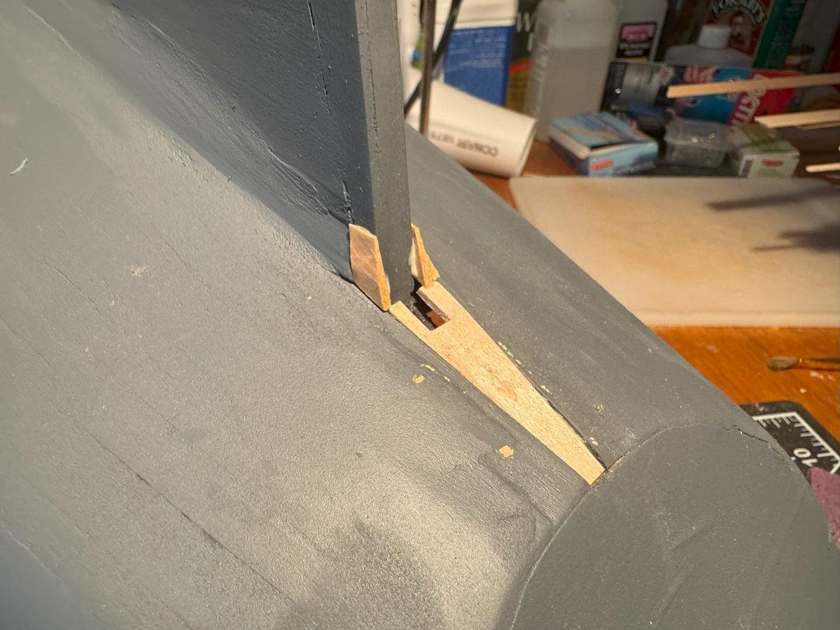
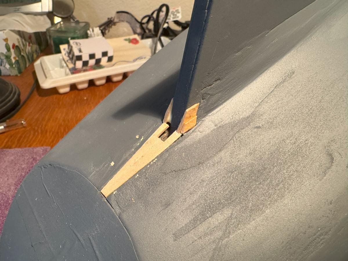
- 90 replies
-
- 5
-
-
- Friendship Sloop
- bluejacket shipcrafters
- (and 1 more)
-
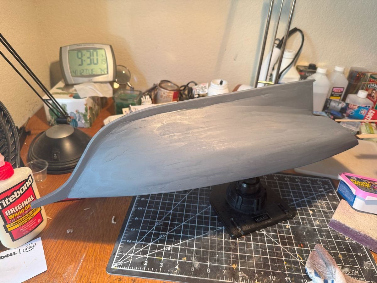
Just about ready for another coat of primer. I hope it will be the last but don't know for sure.
- 90 replies
-
- 5
-
-
- Friendship Sloop
- bluejacket shipcrafters
- (and 1 more)
-
Especially Ferraris that have "Rossa" right in the name of the car . And I agree, the finish looks great, as we are used to seeing from you.
-
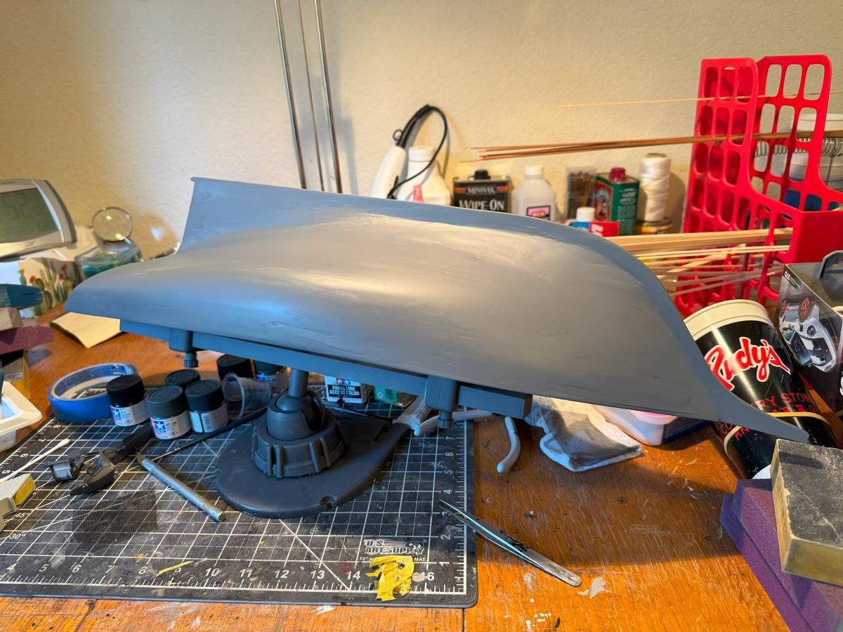
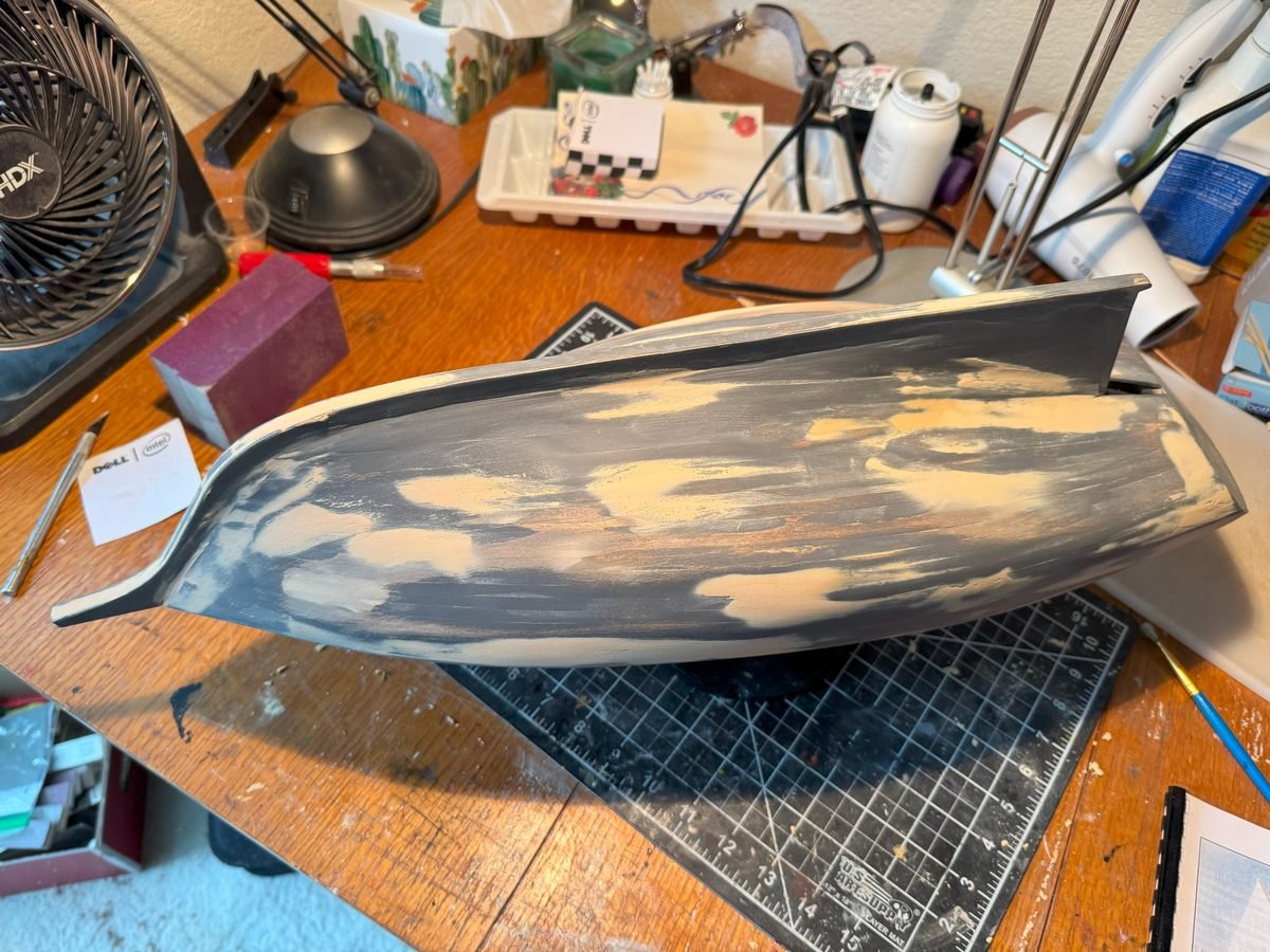
Thanks for the comments and the likes. At the risk of raising expectations that I likely won't meet, I'll make my second post in three days. Since the last one, I have sanded more, added more filler, and sanded again, then sprayed on some primer to get a better look at what still needs to be done. Frankly, the hull looks a bit better in primer than I expected. There are still plenty of spots that need more filler and more sanding, but perhaps fewer than I expected to see. So, I have another couple rounds of filling and sanding, then another coat of primer in my future.
- 90 replies
-
- 5
-
-
- Friendship Sloop
- bluejacket shipcrafters
- (and 1 more)

