Beckmann
-
Posts
445 -
Joined
-
Last visited
8 Followers


Recent Profile Visitors
5,937 profile views


-
 Beckmann reacted to a post in a topic:
Chris Watton and Vanguard Models news and updates Volume 2
Beckmann reacted to a post in a topic:
Chris Watton and Vanguard Models news and updates Volume 2
-
Beckmann reacted to a post in a topic:
Carving from Belgorod
-
Keith Black reacted to a post in a topic:
Carving from Belgorod
-
HAIIAPHNK reacted to a post in a topic:
Carving from Belgorod
-
 Hi Alexandr, This "operation" was really worth the effort. Very well done. The whole composition is very convincing and harmonious. How did you manage to carve the acanthus leave underneath the cape so precise? I am trying to carve acanthus leaves myself at the moment, they are not half as good as yours. Can you show us your tools? Is this done by milling or carving? Matthias
 -
Beckmann reacted to a post in a topic:
Carving from Belgorod
-
Beckmann reacted to a post in a topic:
Christiania 1774 by TJM – approx. 1:67-1:64 – Danish Light Frigate based on Vanguard Models HMS Sphinx
-
Beckmann reacted to a post in a topic:
Christiania 1774 by TJM – approx. 1:67-1:64 – Danish Light Frigate based on Vanguard Models HMS Sphinx
-
Canute reacted to a post in a topic:
TRE KRONER 1742 by Beckmann - 3"/8' scale - Transom-Model
-
Beckmann reacted to a post in a topic:
Christiania 1774 by TJM – approx. 1:67-1:64 – Danish Light Frigate based on Vanguard Models HMS Sphinx
-
Heimdahl reacted to a post in a topic:
TRE KRONER 1742 by Beckmann - 3"/8' scale - Transom-Model
-
Beckmann reacted to a post in a topic:
Christiania 1774 by TJM – approx. 1:67-1:64 – Danish Light Frigate based on Vanguard Models HMS Sphinx
-
Beckmann reacted to a post in a topic:
Carving from Belgorod
-
Beckmann reacted to a post in a topic:
Carving from Belgorod
-
GrandpaPhil reacted to a post in a topic:
TRE KRONER 1742 by Beckmann - 3"/8' scale - Transom-Model
-
HAIIAPHNK reacted to a post in a topic:
TRE KRONER 1742 by Beckmann - 3"/8' scale - Transom-Model
-
CiscoH reacted to a post in a topic:
TRE KRONER 1742 by Beckmann - 3"/8' scale - Transom-Model
-
dvm27 reacted to a post in a topic:
TRE KRONER 1742 by Beckmann - 3"/8' scale - Transom-Model
-
Cpt.Barbossa reacted to a post in a topic:
TRE KRONER 1742 by Beckmann - 3"/8' scale - Transom-Model
-
druxey reacted to a post in a topic:
TRE KRONER 1742 by Beckmann - 3"/8' scale - Transom-Model
-
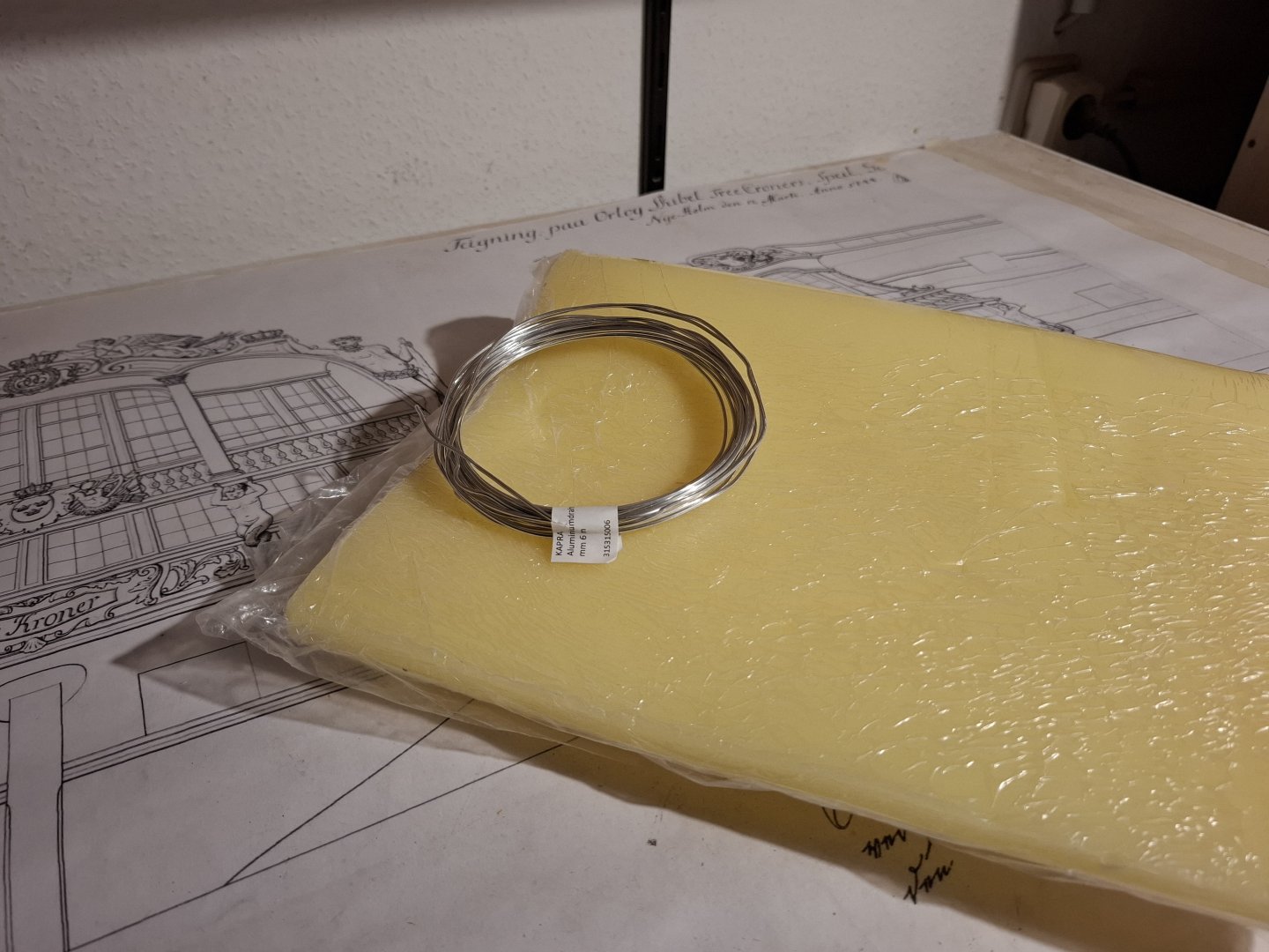
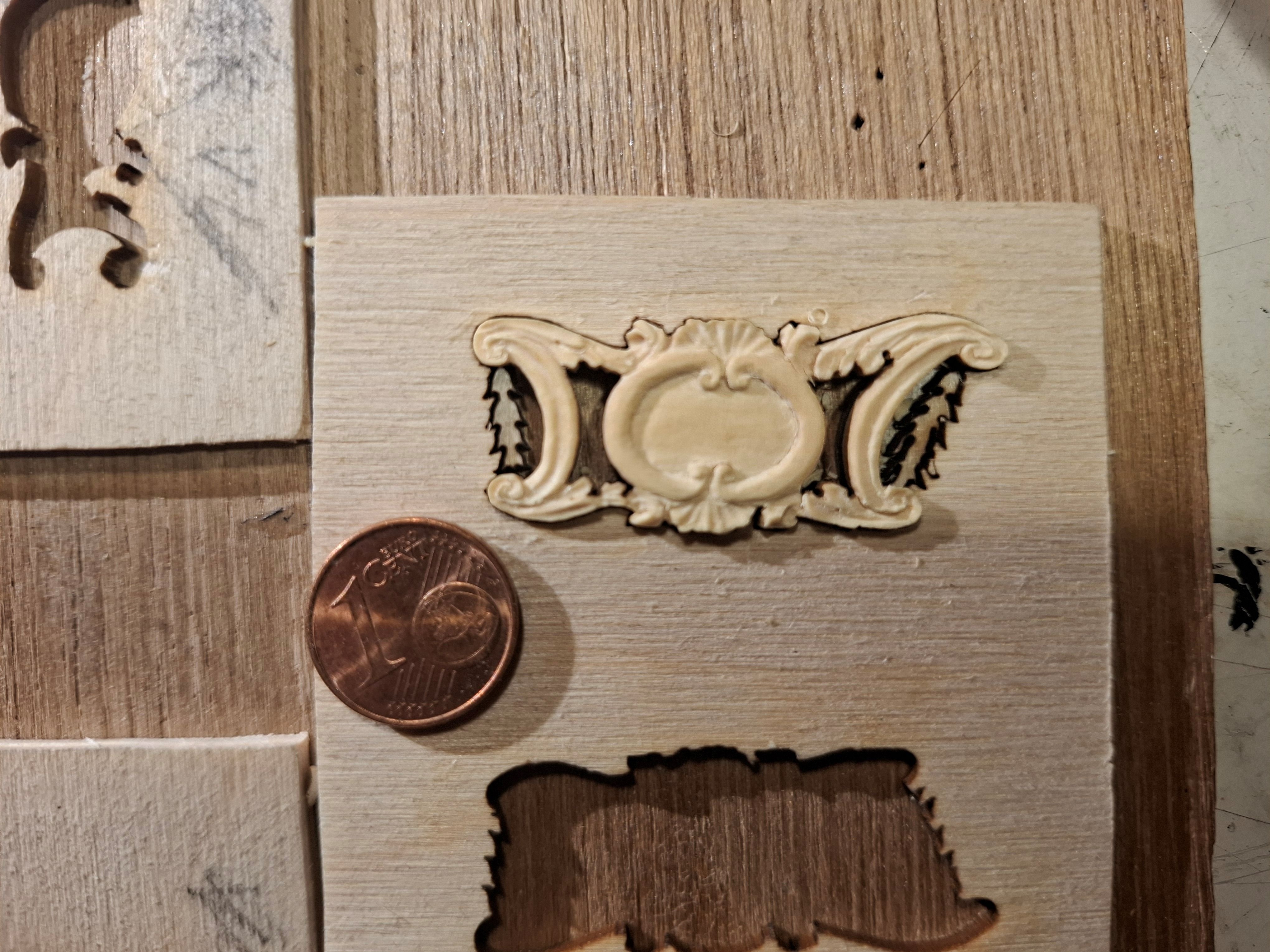
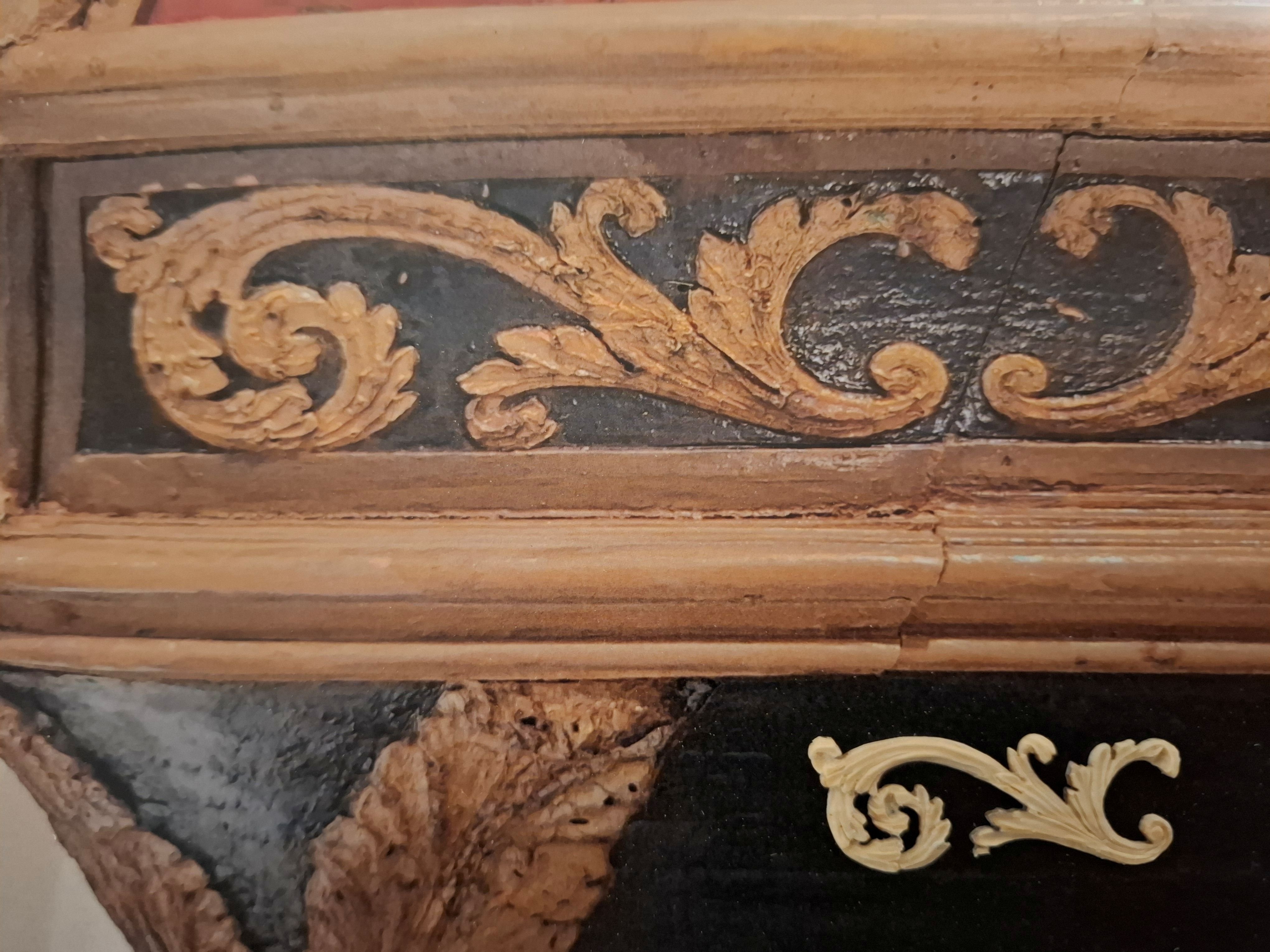
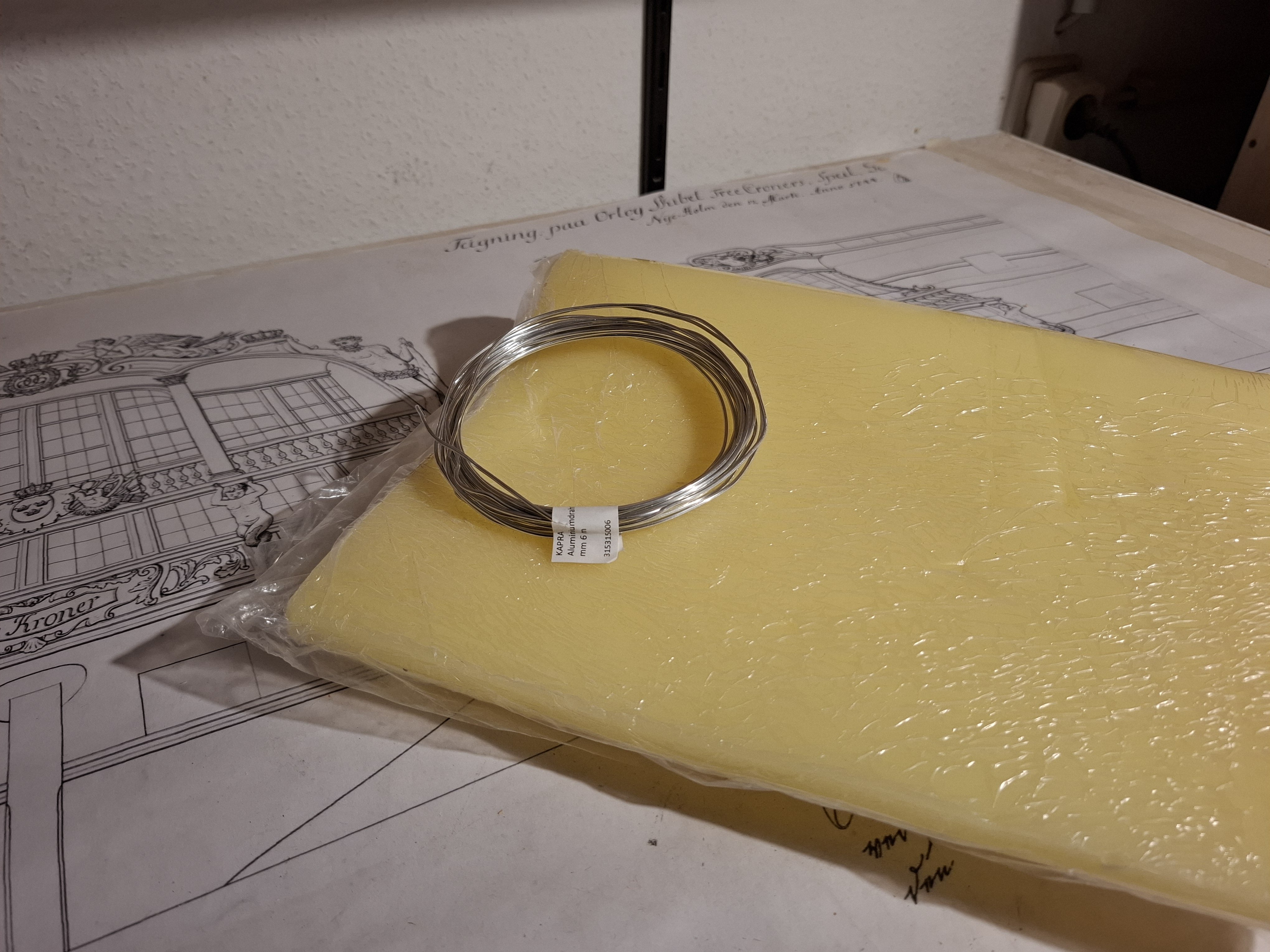
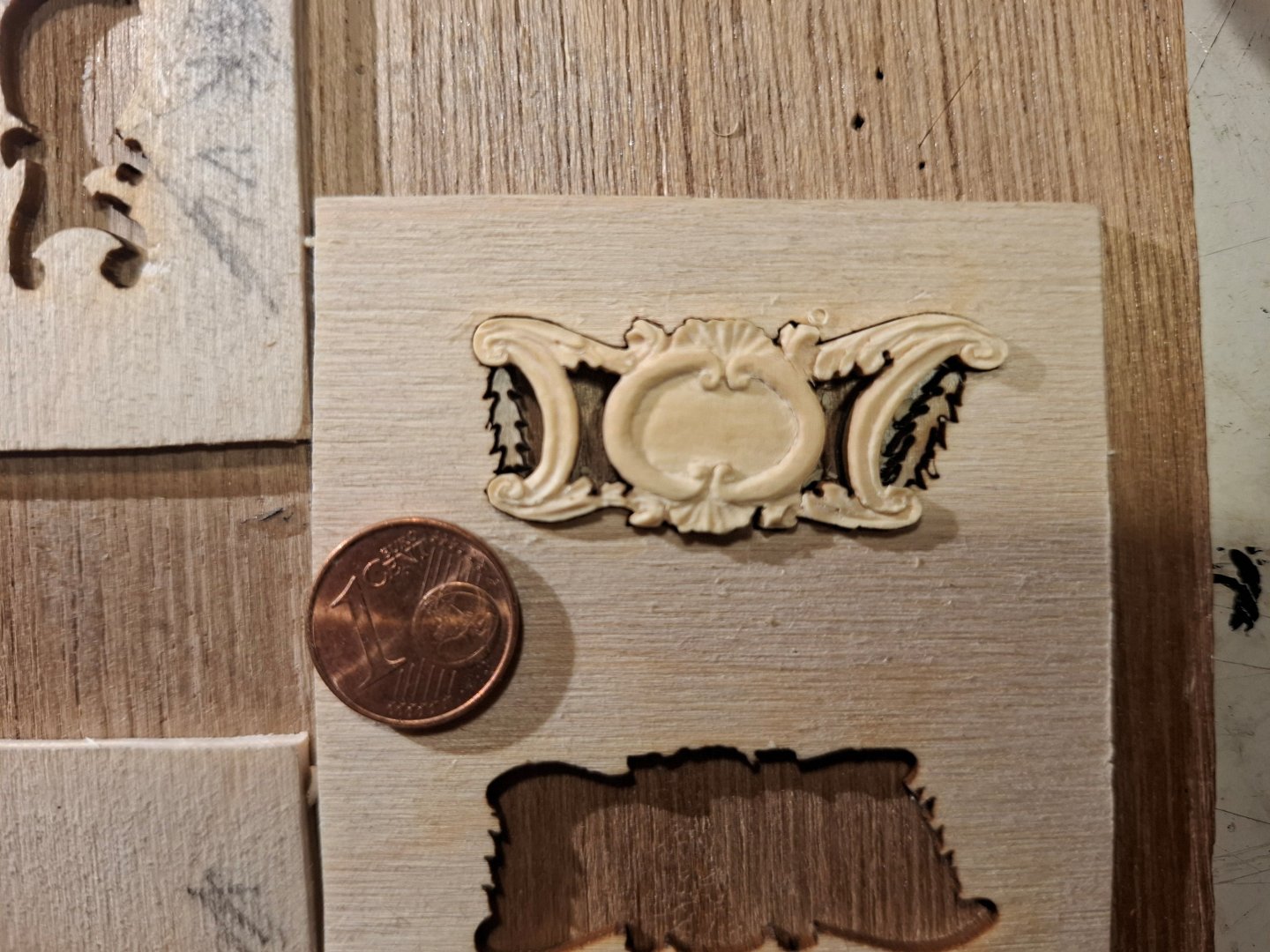
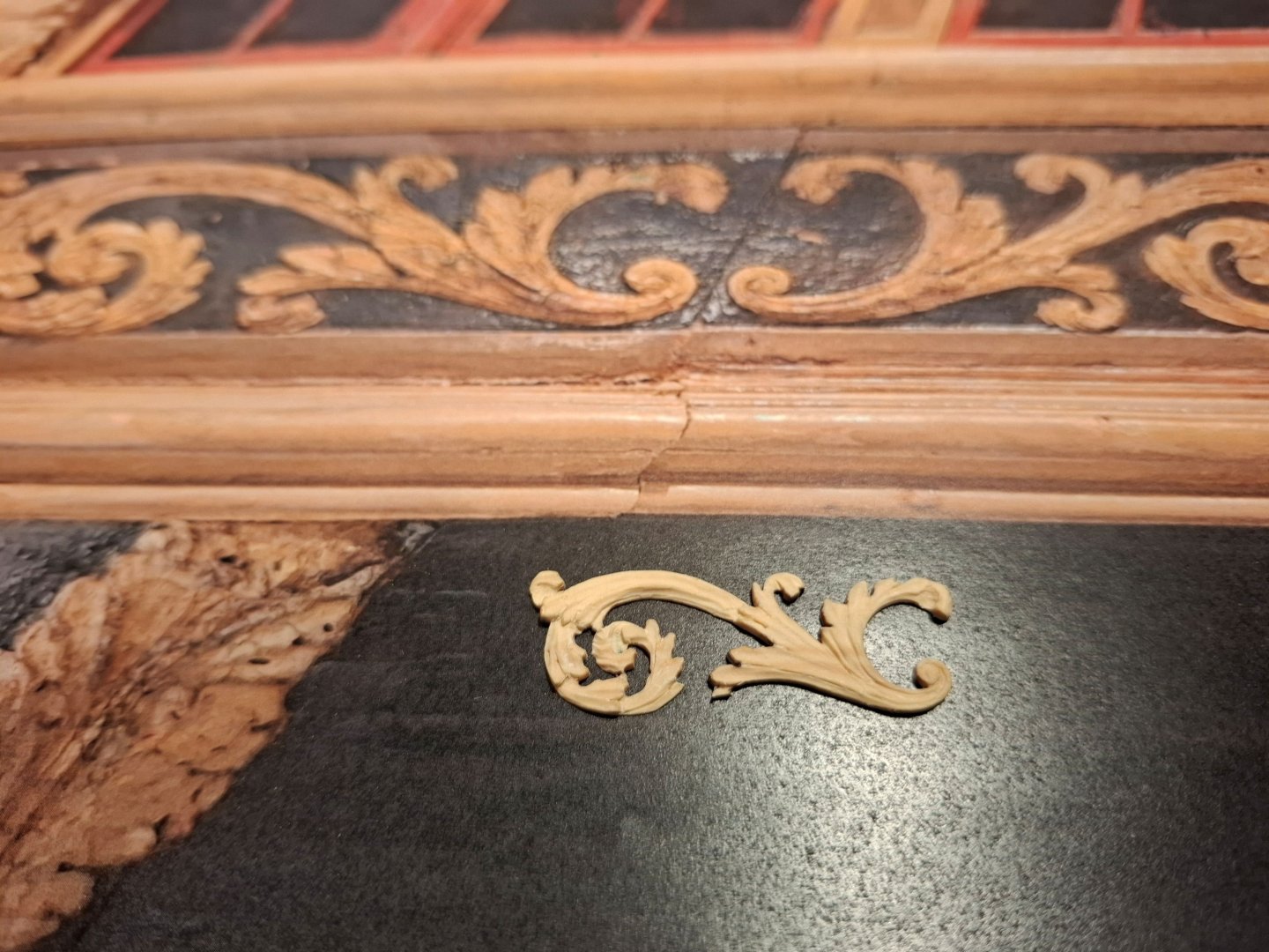
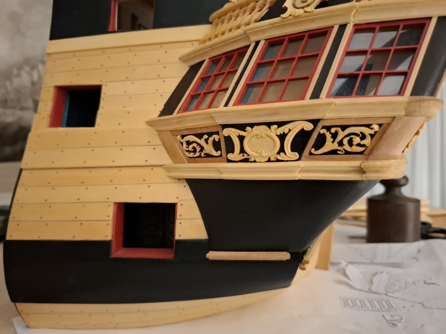
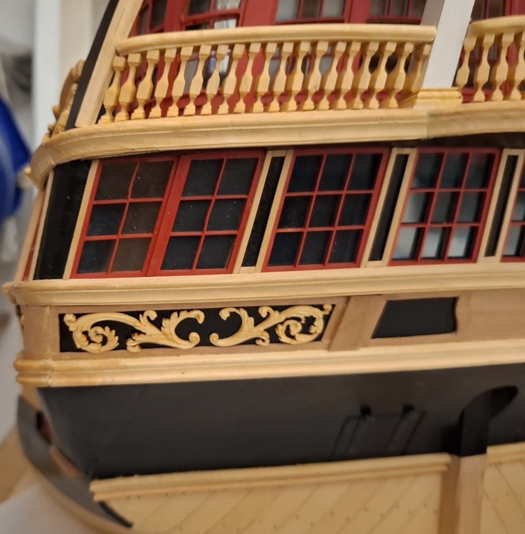
Dear fellow model builders, Thank you for your comments and likes. Recently, I have been working on the ornaments on my model. I have already presented the bas-reliefs on the roof surface, and now I am continuing with the surfaces below the gallery level. These are decorated with acanthus garlands, which were executed as flat wax reliefs on the original model. I have purchased modeling wax, but I am sticking with boxwood for the design. I am still a little unfamiliar with the wax, and it is also very delicate. To make it possible to carve these delicate parts at all, I laser-cut a frame in the shape of the ornaments, into which they can be loosely inserted. This worked surprisingly well. The part can be worked on easily there, nothing slips away, and when pressure is applied, the garland lies against the edge of the mold without breaking. The garlands initially have a material thickness of approx. 2.5 mm. Once the shape has been carved from the “top,” working approx. 1.5 mm, it is sanded down from the back until it is approx. 1 to 1.5 mm thick overall. This makes it very fragile, of course, but that doesn't matter because it only needs to be placed on the fields. Despite the very stiff boxwood, the ornament can be easily bent to fit the partially rounded surface. Holding it in place for a moment after gluing is enough to ensure that everything stays where it should. Then dab the ornament with a little furniture oil, which will deepen the color. Best regards, Matthias

-
I was talking of a close resemblance to Alexander I. Pawlowitsch Romanow Matthias
-
similar to Czar Alexander, the busts and paintings you showed above depict Czar Alexander, don't they?
-
Hi Alexandr, The face of the emperor has already much resemblance with Alexander. Are you carving in boxwood or limewood? Matthias
-
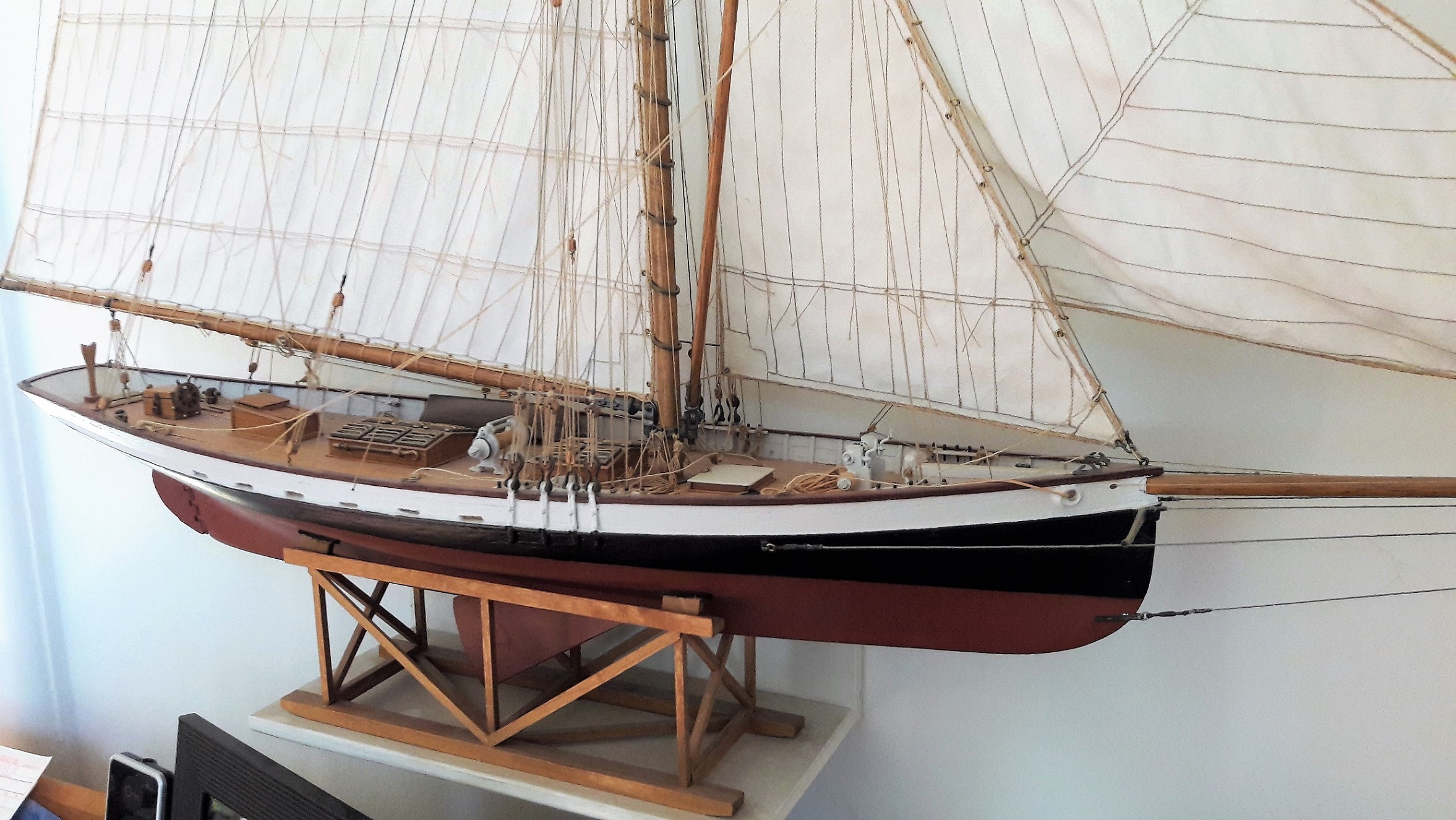
Very nice result Thorbjørn!! I remember my first build was an upcycled kit of victory models (HMS Unicorn) I learned so much in that time. Apart from the Syren projects, that was my last kit. It made me begin with scratch-projects. That will be your modelling-future as well I suppose. Matthias
- 144 replies
-
- 2
-

-
-
- Christiania
- Vanguard Models
- (and 1 more)
-
Hi Thorbjörn, that looks superb, well done!! Matthias
- 144 replies
-
- 3
-
-
-
- Christiania
- Vanguard Models
- (and 1 more)
-
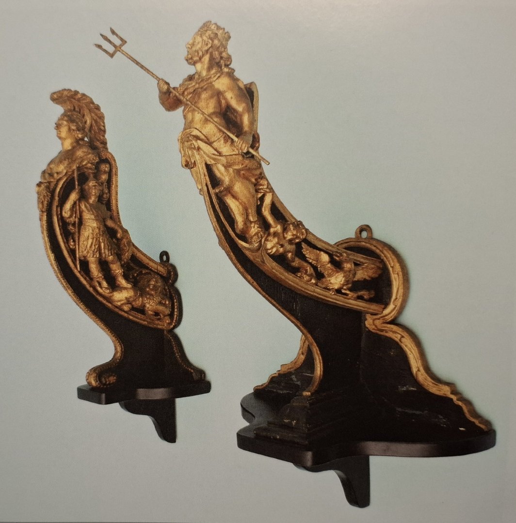
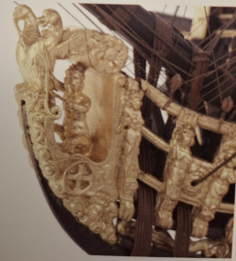
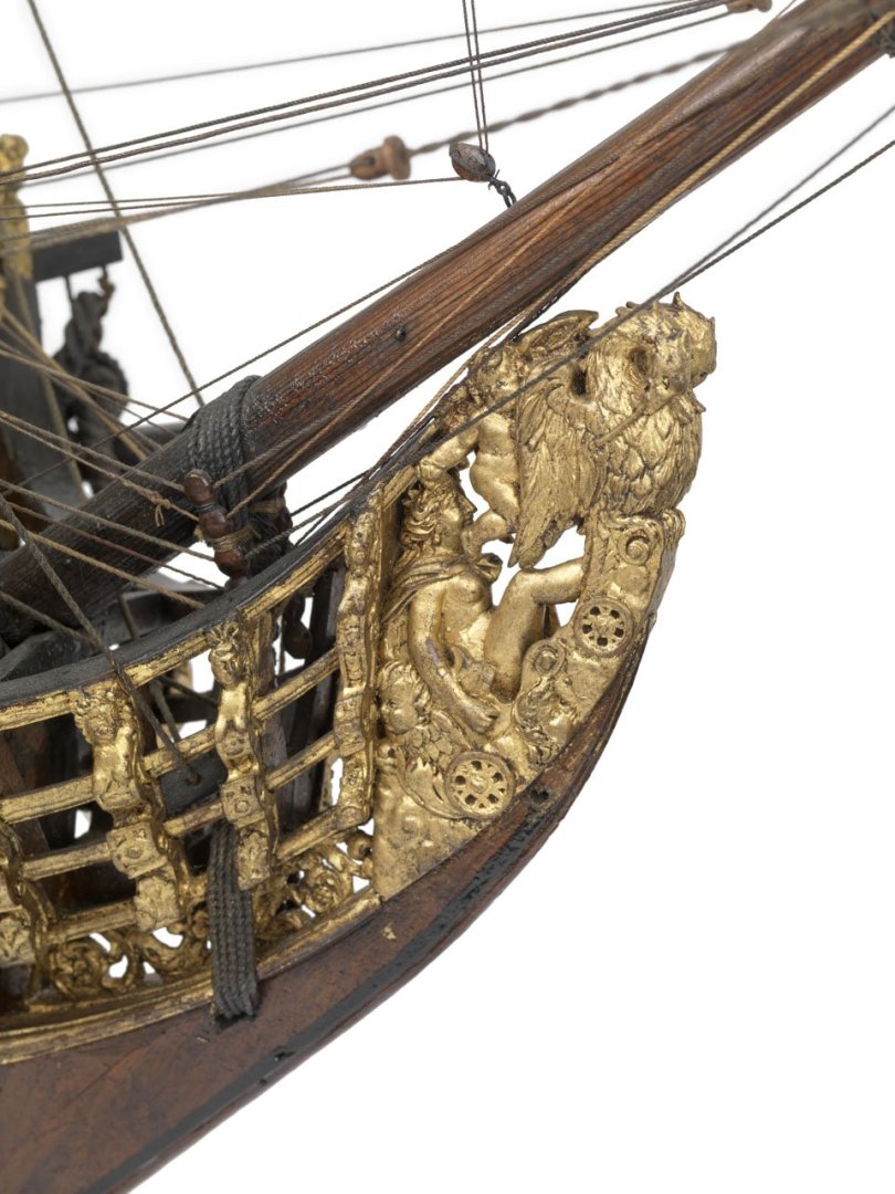
Hi Alexandr, That was really just a coincidence. I just opened my book Volume 1 Rogers Collection in Annapolis and there it was. Here are two better pictures. Also interesting: Rogers Collection Volume 2 page 34: Figureheads depicting Minerva and Neptun. (watch the helmet :)) and from the book Navy board ship models: Second Rate from 1675: SLR 0003 Allegorie of a crowned figure being carried over the water in a chariot, drawn by eagles. Same figurehead see SLR 0002 St Michael: And SLR 0386 First Rate from 1702 a figurehead depicting the abduction of Europe by Zeus. Matthias


-
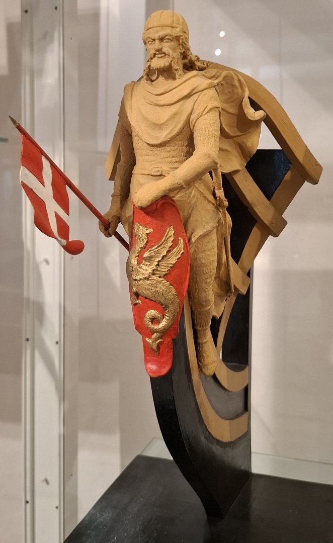
Well, do you know the figurehead of 90 gun ship of the line St Georg from the year 1701? It shows St Georg fighting a dragon. Ther are a couple of models, often before 1703 with mythological figurehead-arrangements . If you want, I can send you some more photos.

-
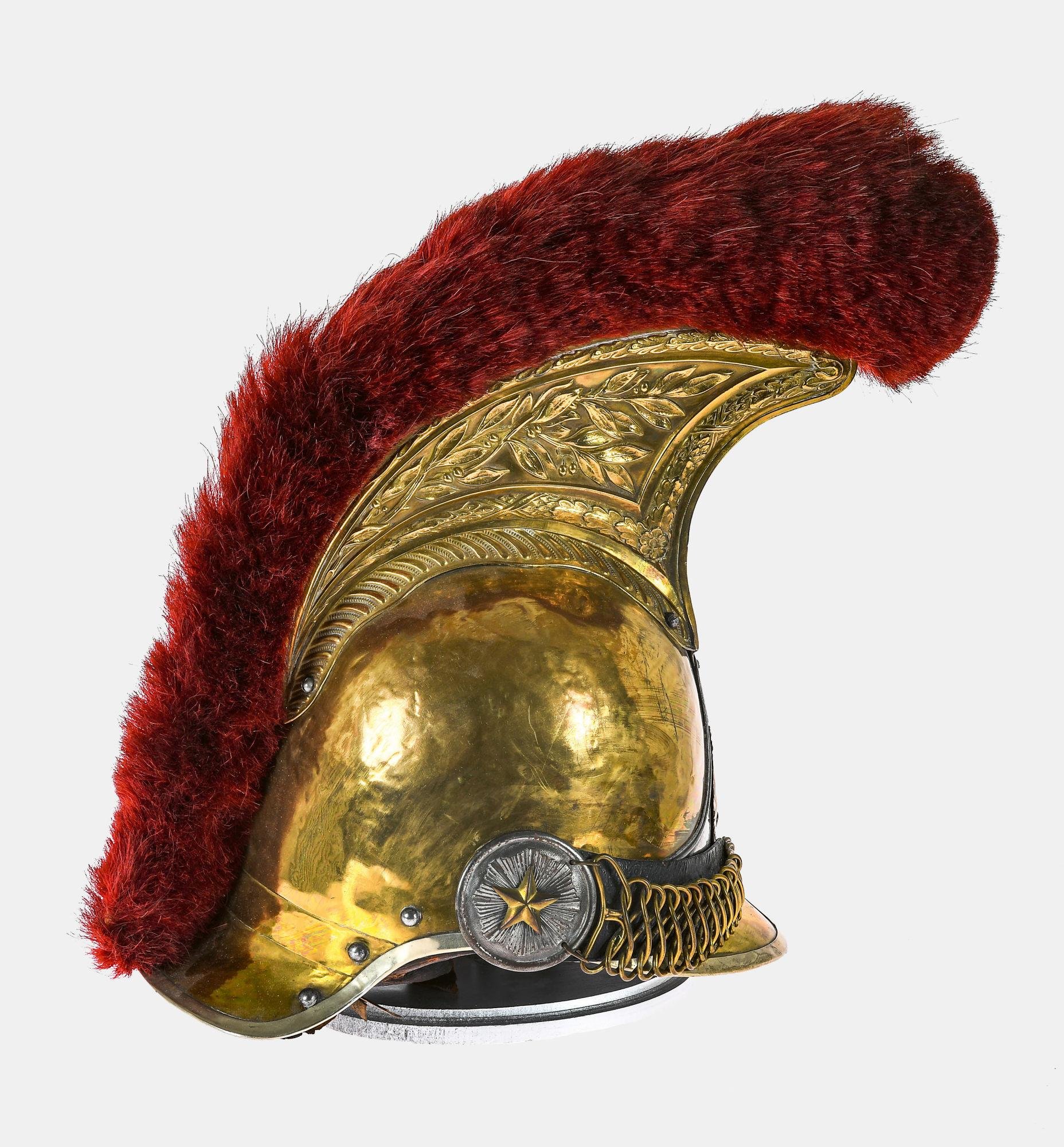
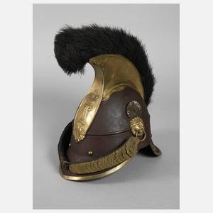
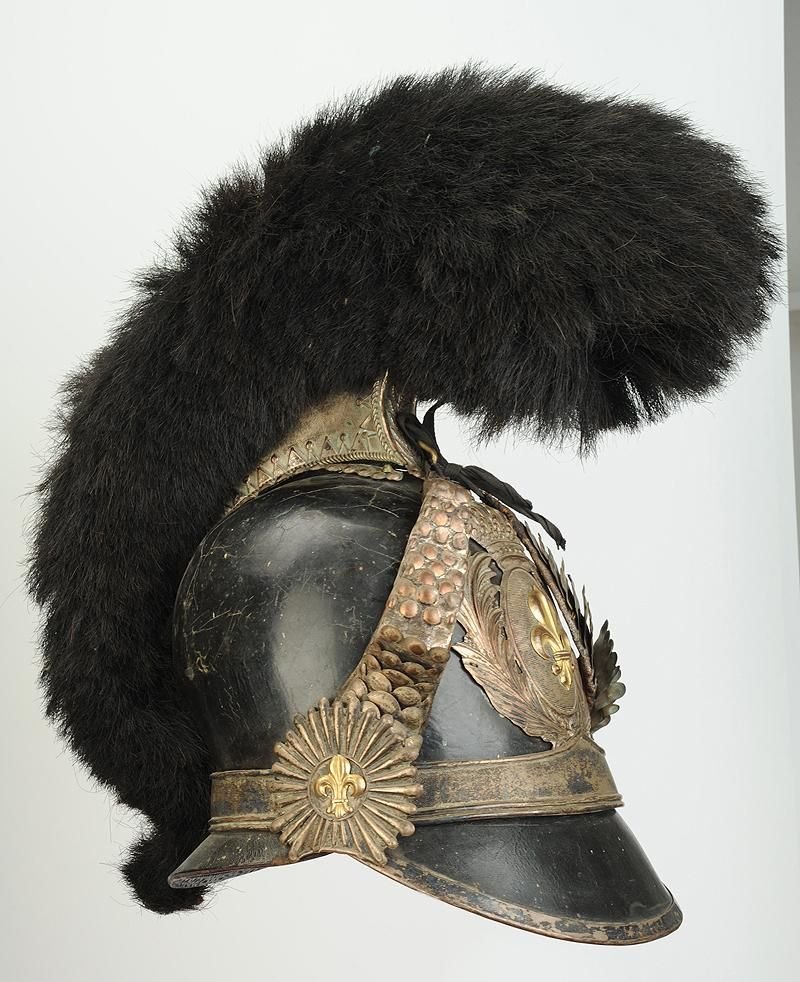
Hi Alexandr, the bavarian and the french army used to have such helmets, here are some examples from the middle of the 19th. century. Matthias

-
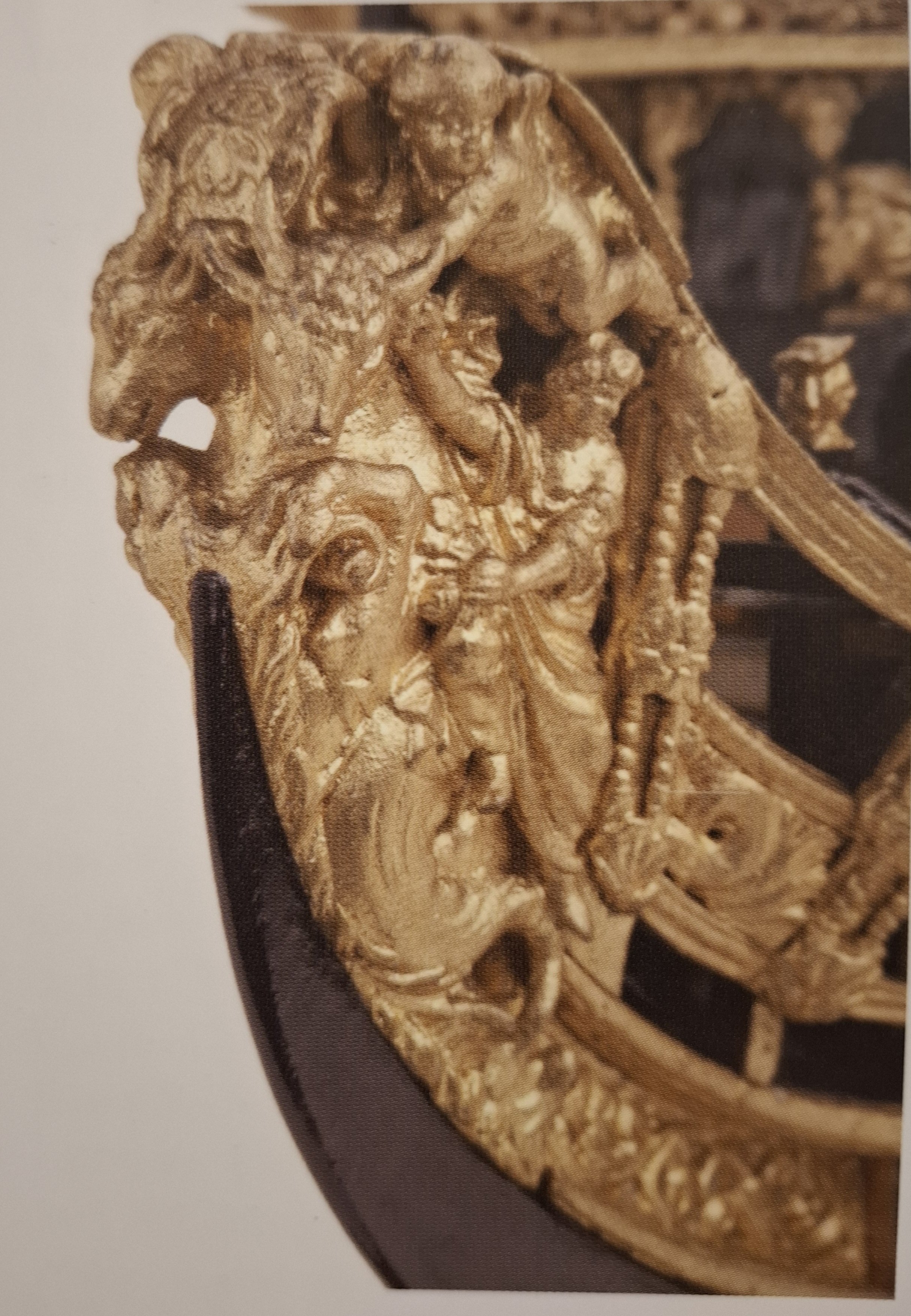
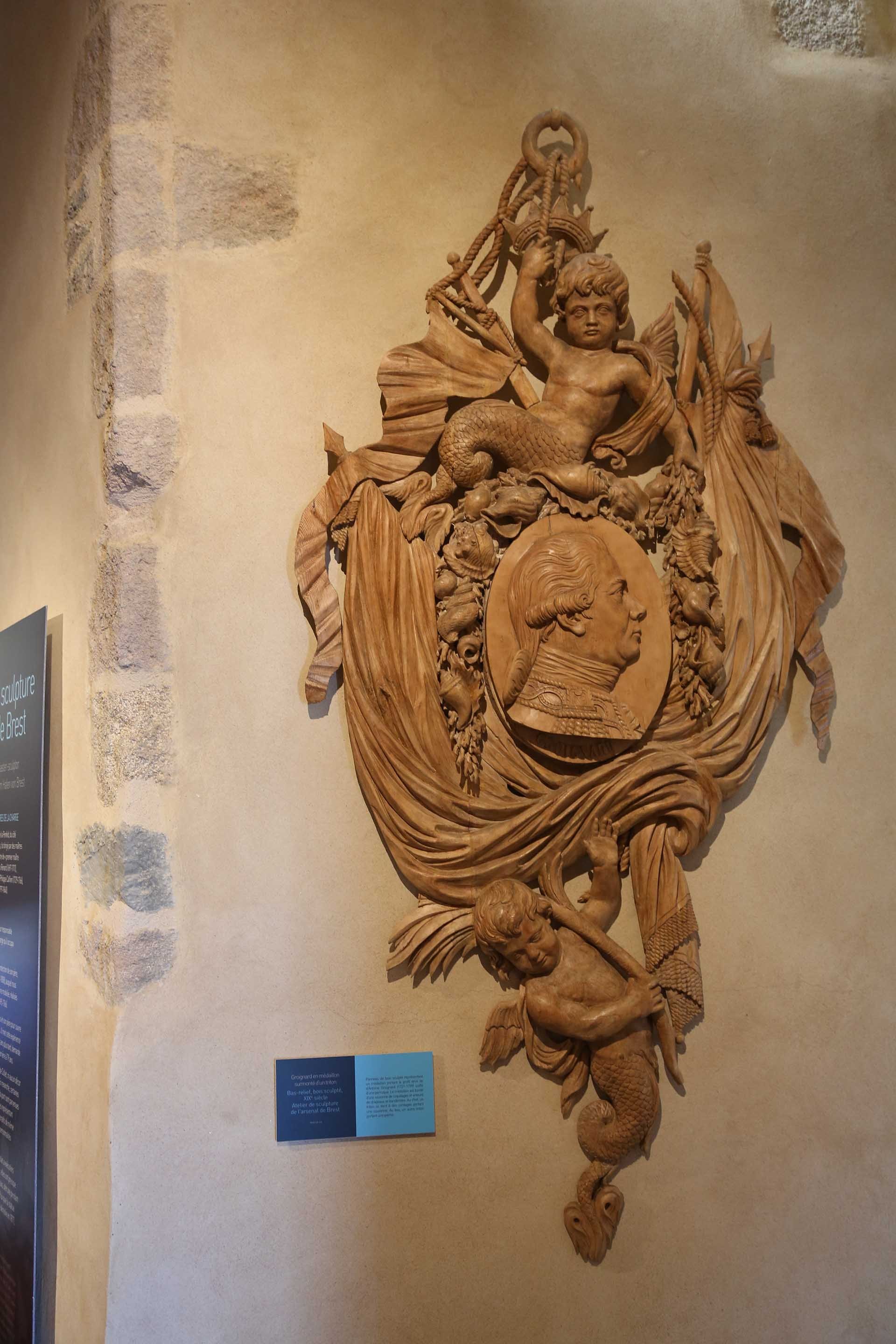
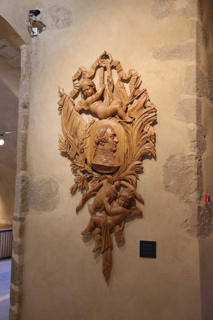
These people were quite International. Wiedewelt learnt his art in the Netherlands in 1692 he was for 4 years assistant of dutch carver Thomas Quellinus. Afterwarts 2 years at Antwerpen with Artur Quellinus.(Father of Thomas). From 1698 to 1715 he worked in Paris. From 1715 on he was in Kopenhagen, were he stayed the rest of his life .Thomas Quelinus had been a carver at Kopenhagen as well,.before he moved to the Netherlands. I think in those times everybody looked at Paris. French stile and art at the court of Louis Quatorze was the ultimate example. That is him. The Medaillon was made by his son Johannes Wiedewelt, who was a famous sculptor himself, but not in maritime context. Matthias

-
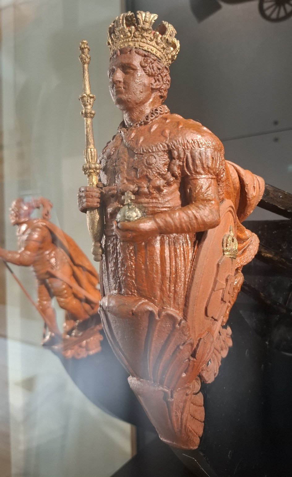
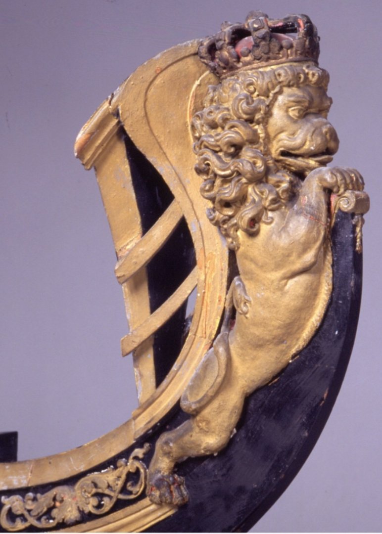
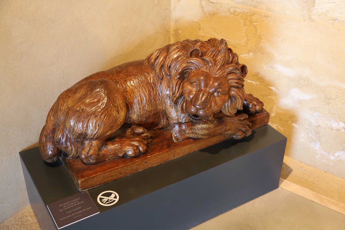
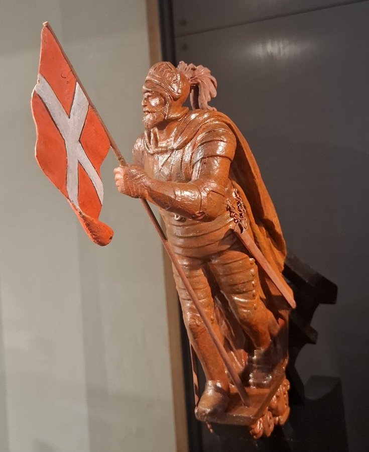
Hi Alexandr, the reason is, that there was no german navy before the ironclads. The Hansestädte like Lübeck and Hamburg had a small navy and Prussia and Austria. Later Schleswig-Holstein as well. But often there was no lokal shipyard-capacity and so, they purchased ships at the Netherlands and in England. There was a wooden german merchant navy, but these ships usually had no lions as figureheads, because that is a royal symbol. The Altona Museum has got a nice collection of figureheads of merchant ships. For now I can offer a danish Lion, made by Just Wiedewelt in the 1740's. He came from Germany,.from the city Schleiz in Saxony, but worked at Kopenhagen for the danish navy. You might know this example. Matthias
-
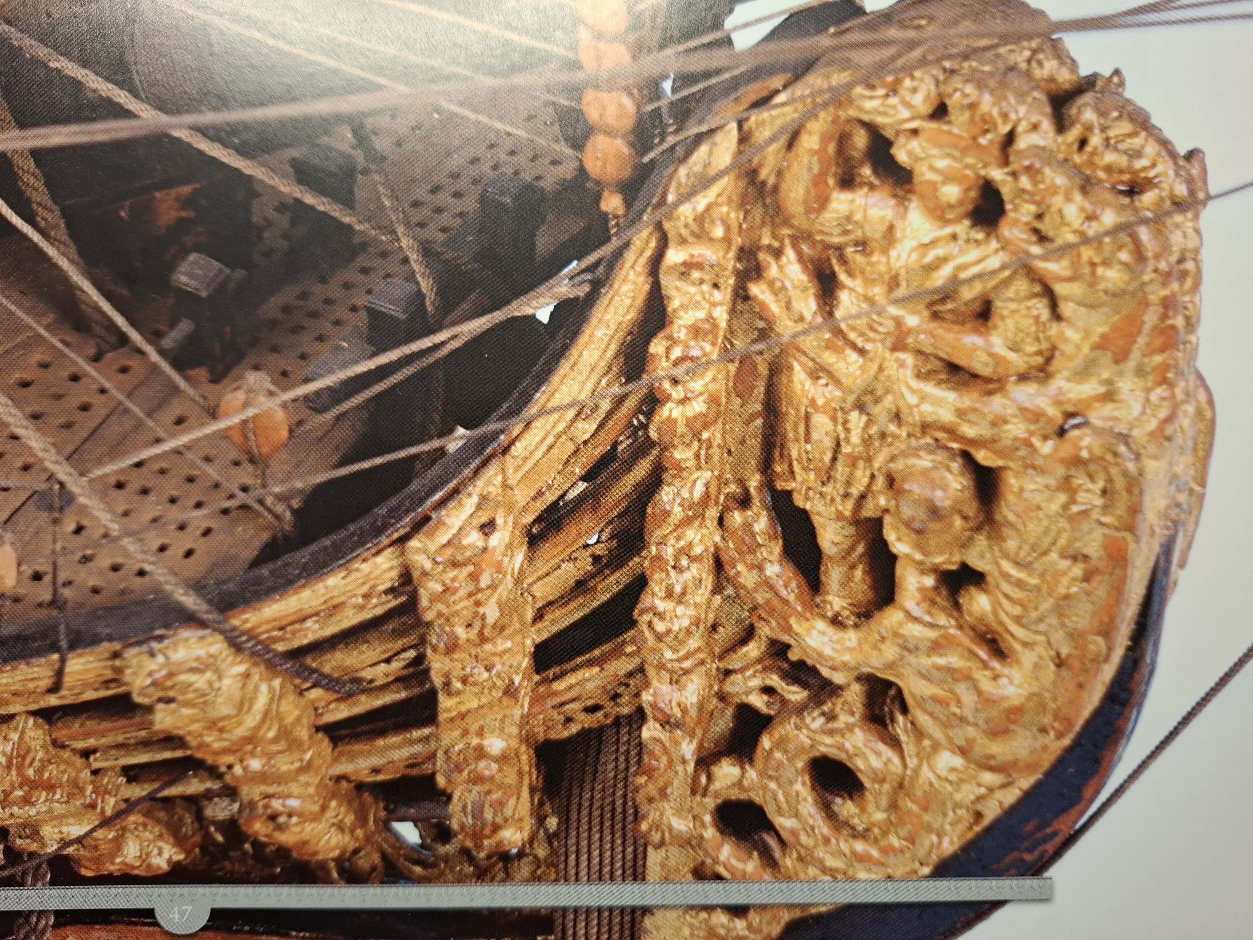
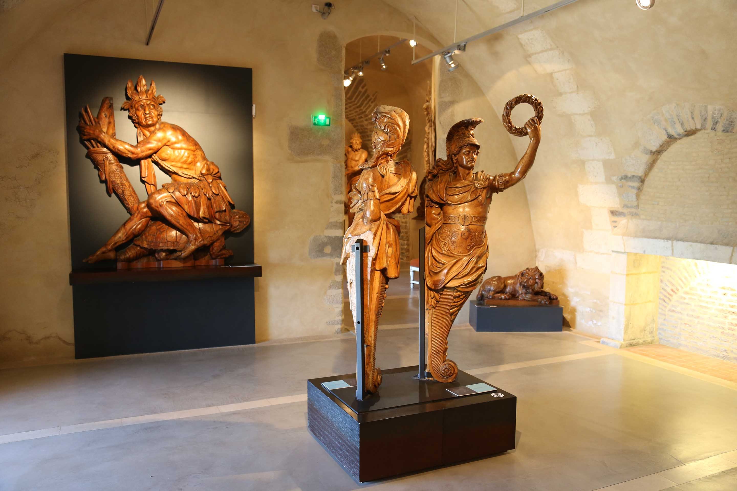
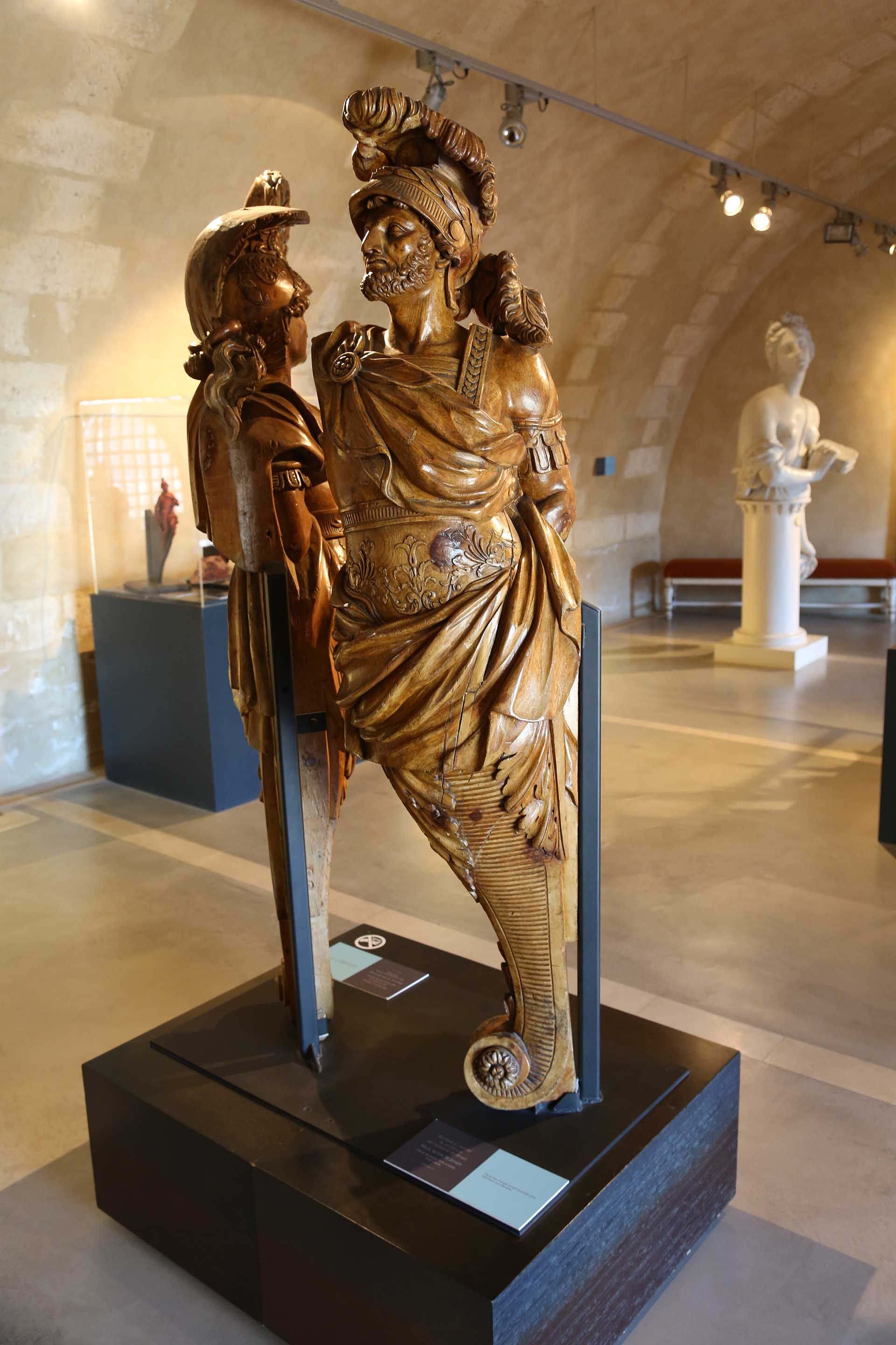
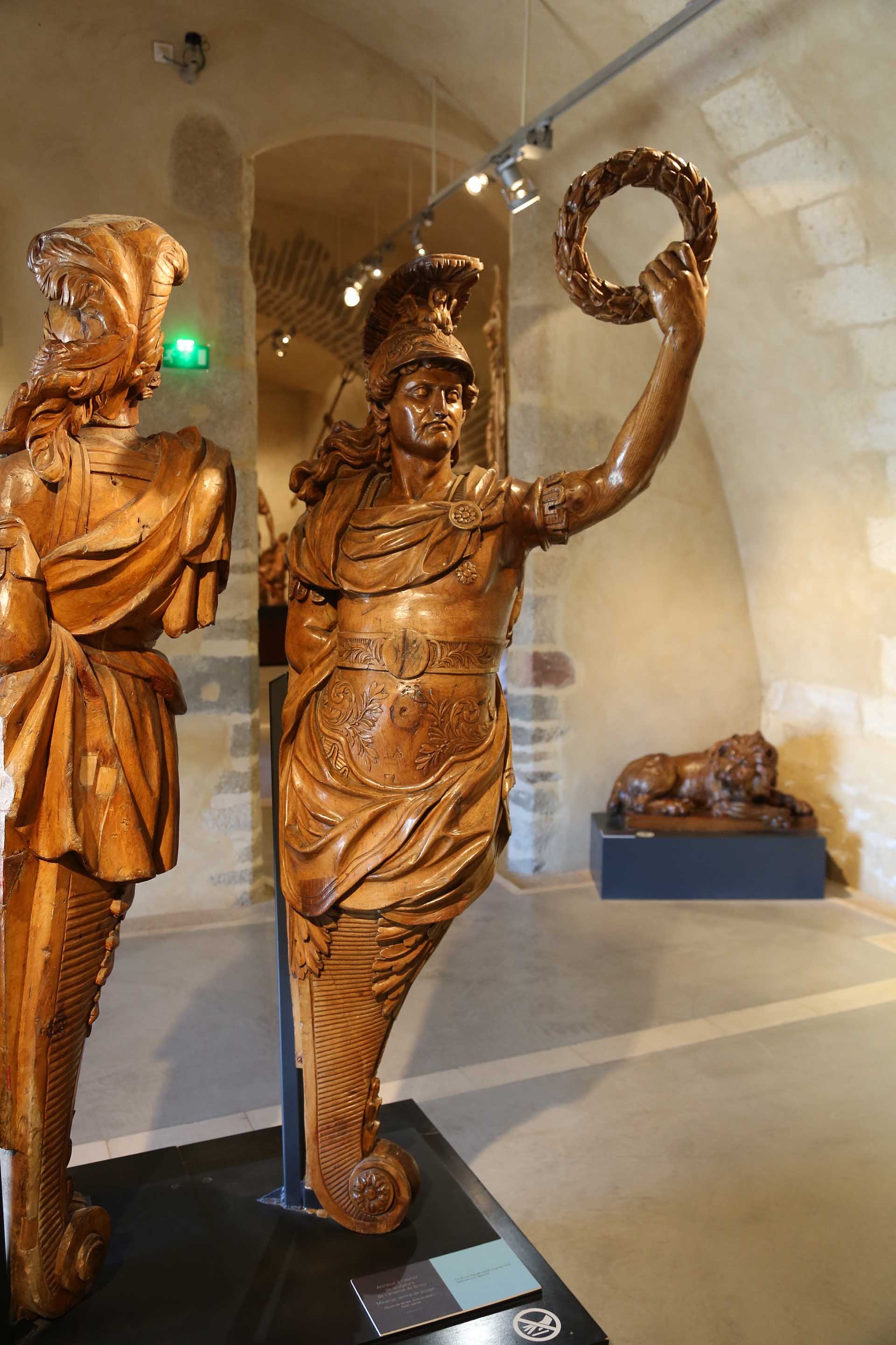
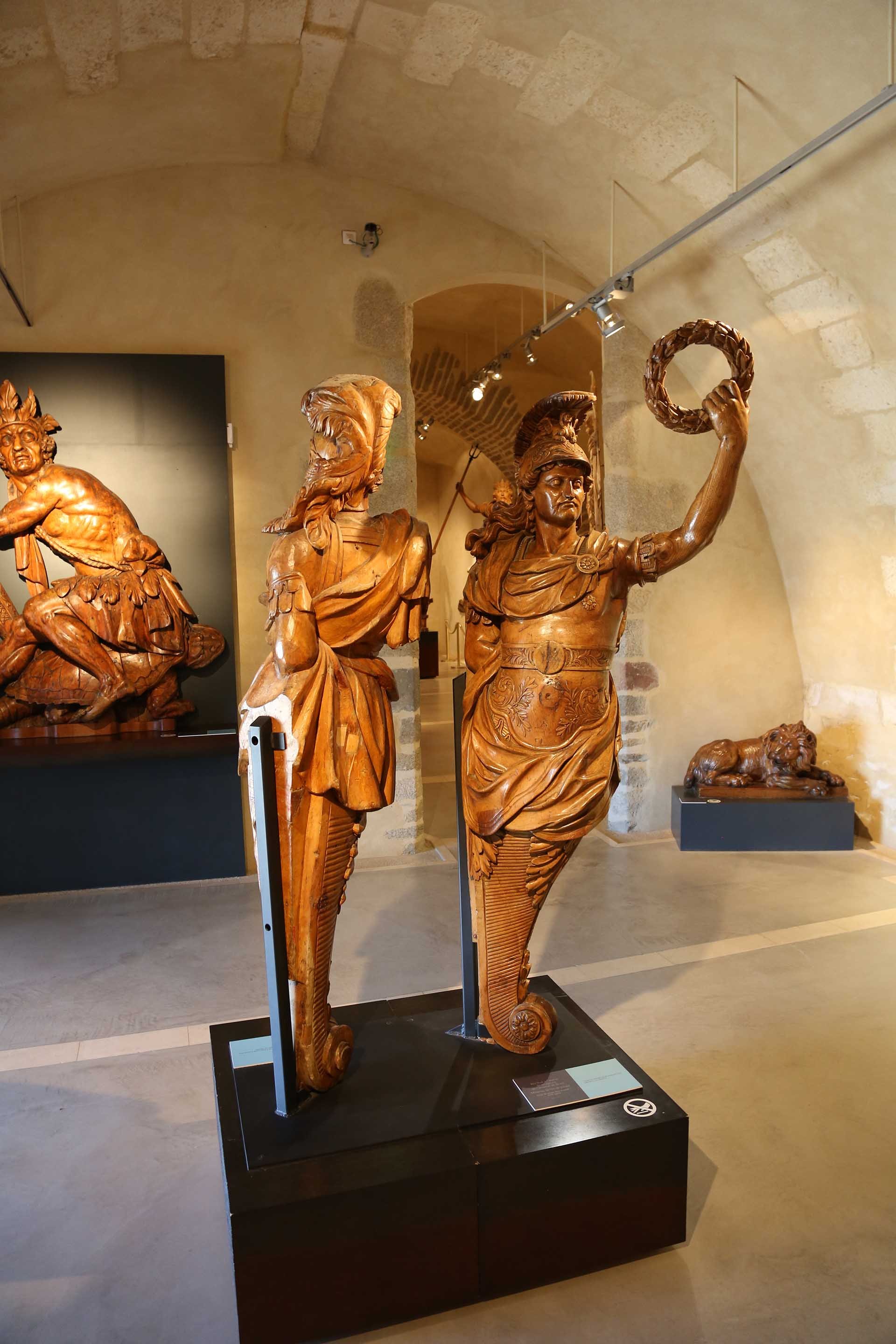
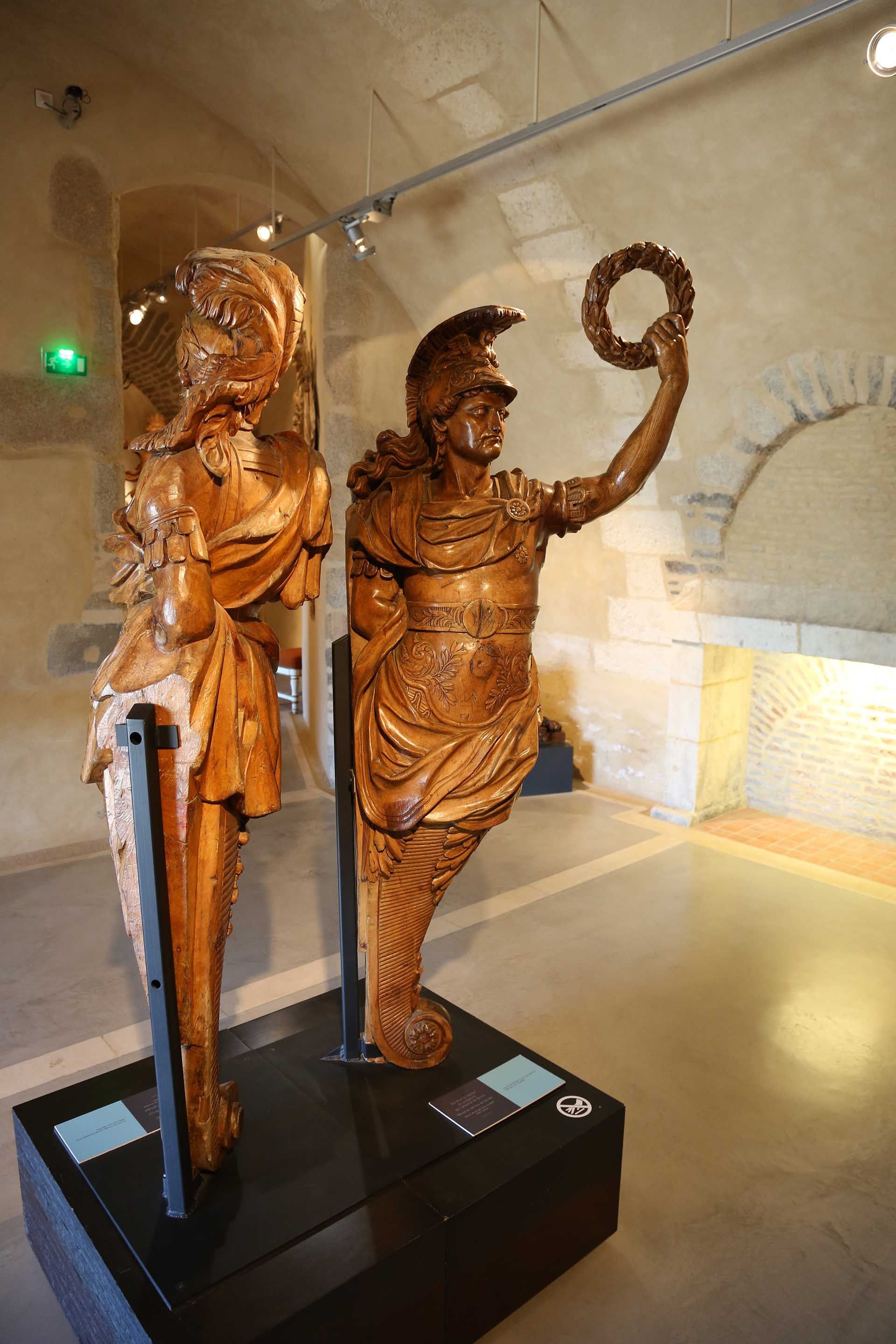
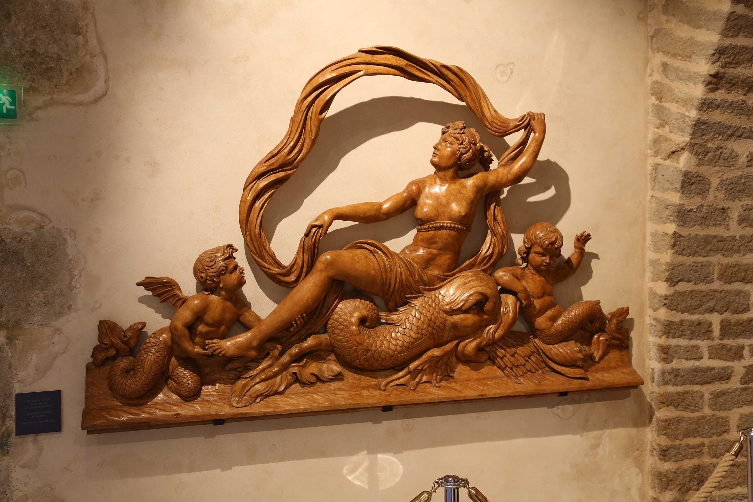
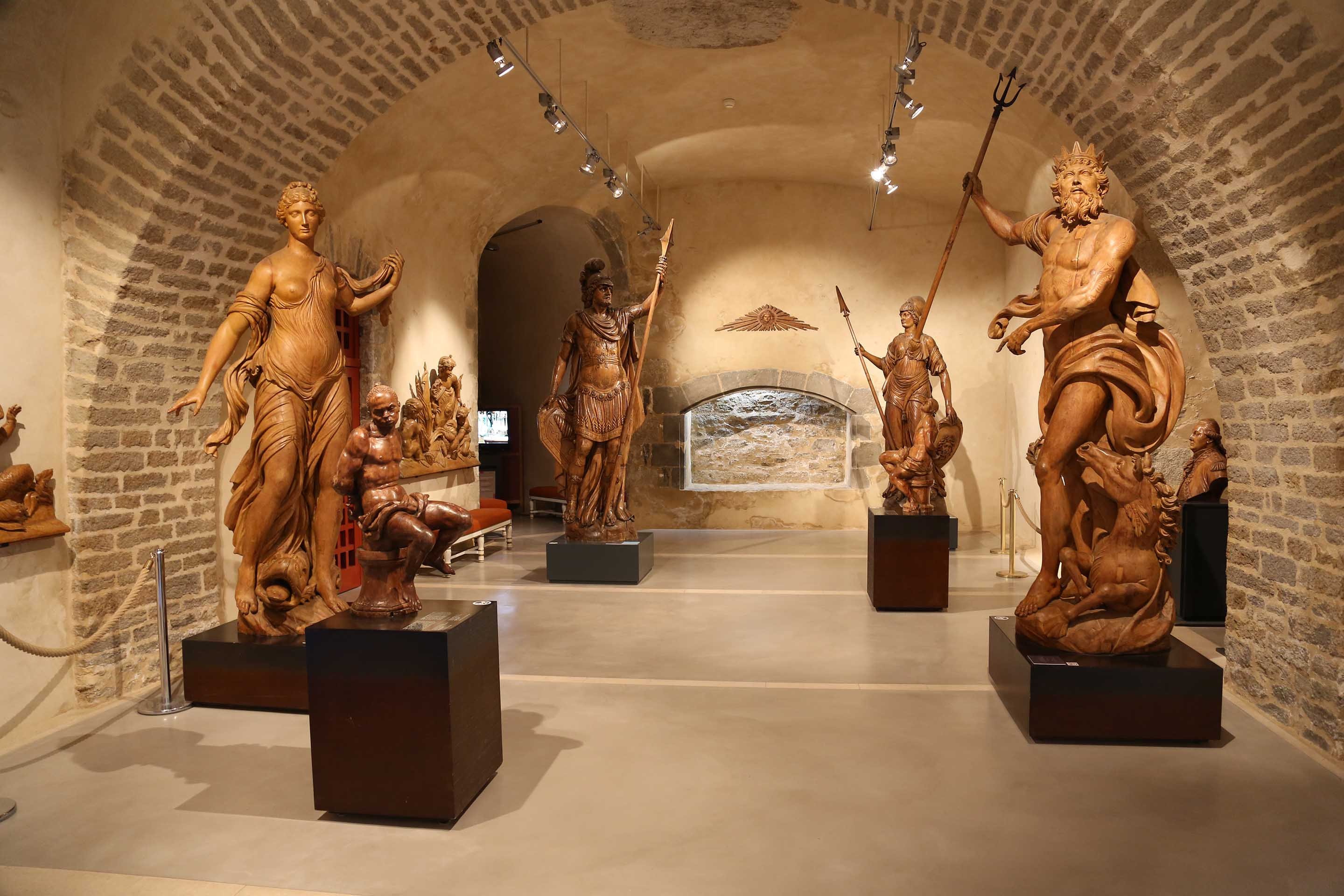
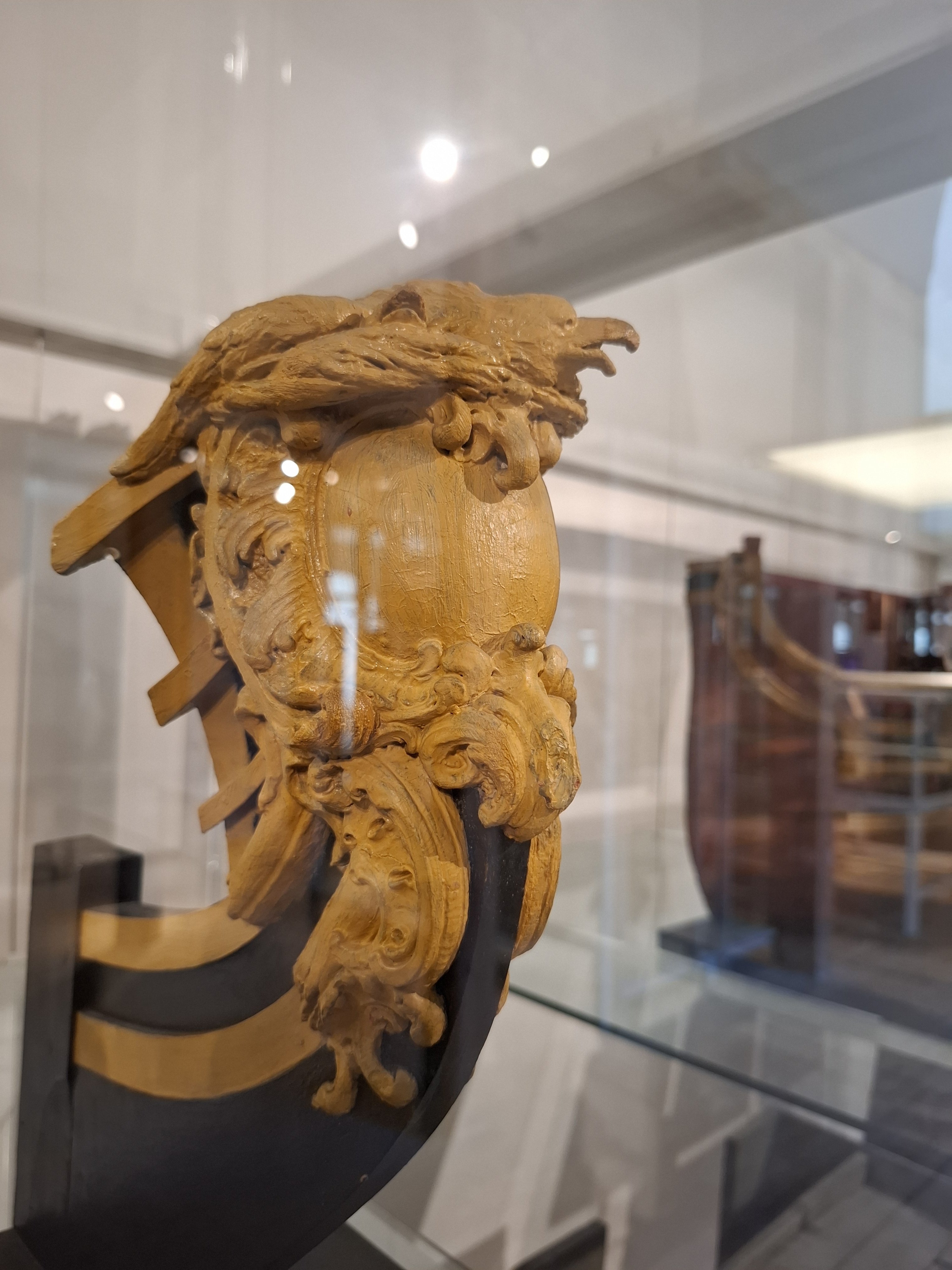
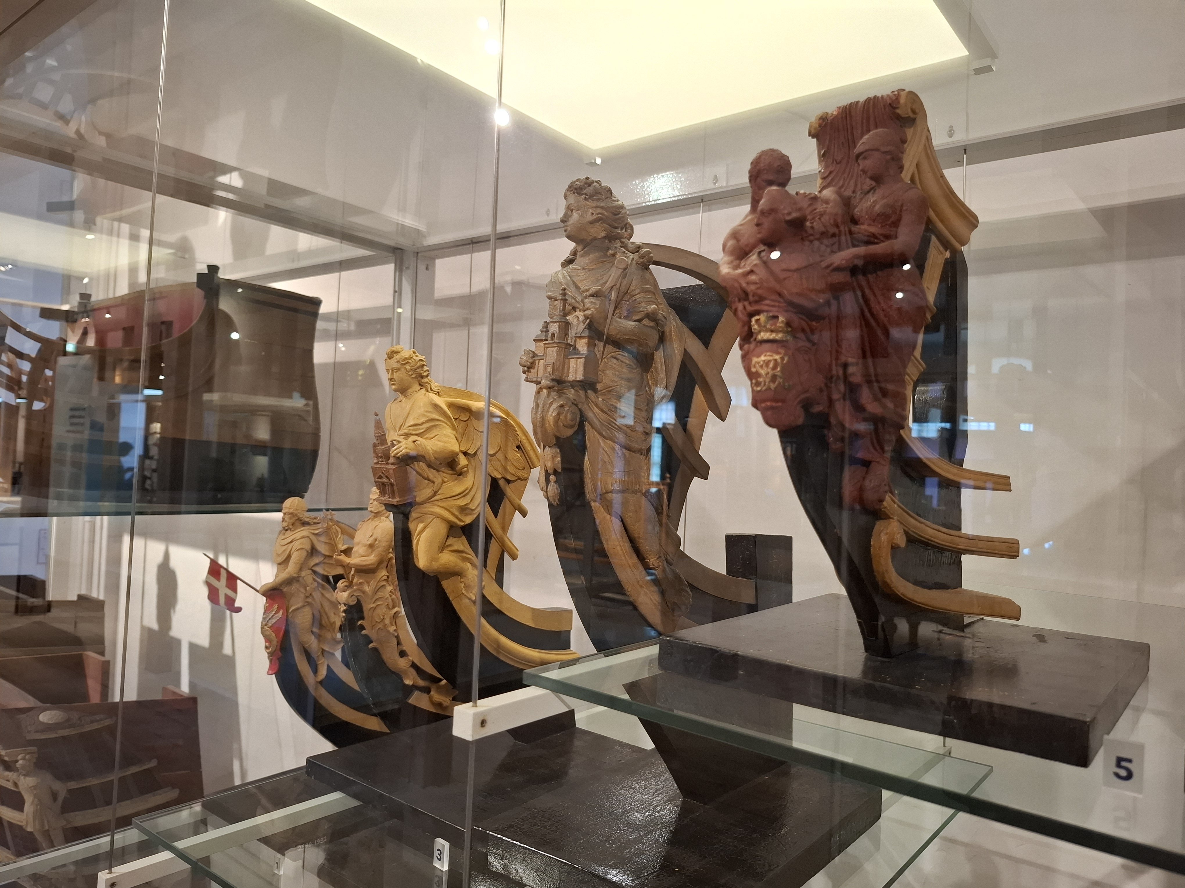
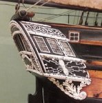
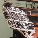
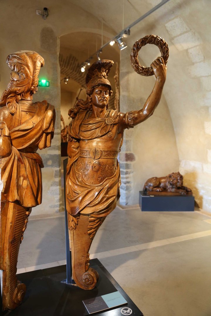
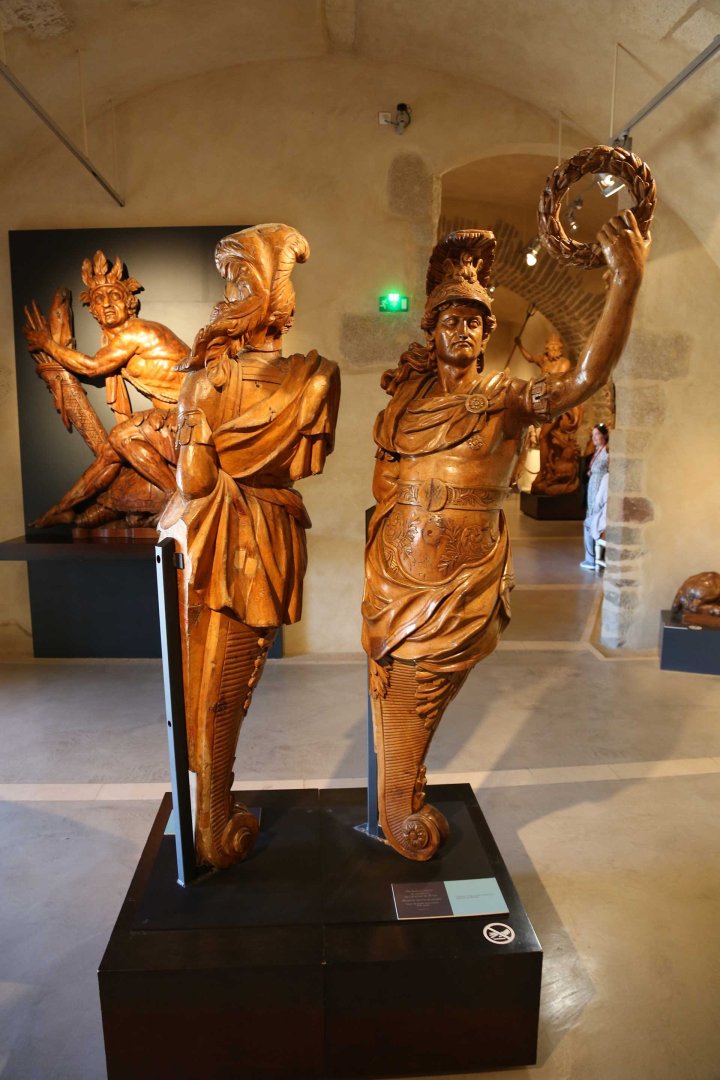
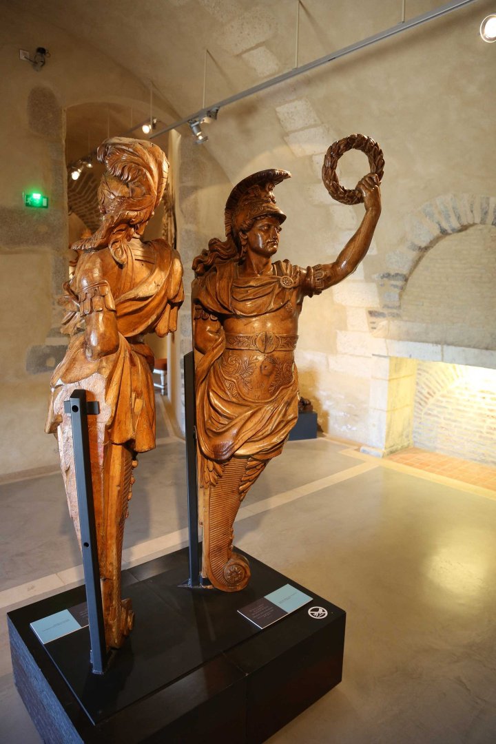
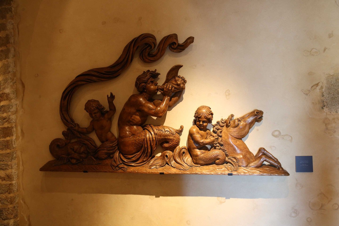
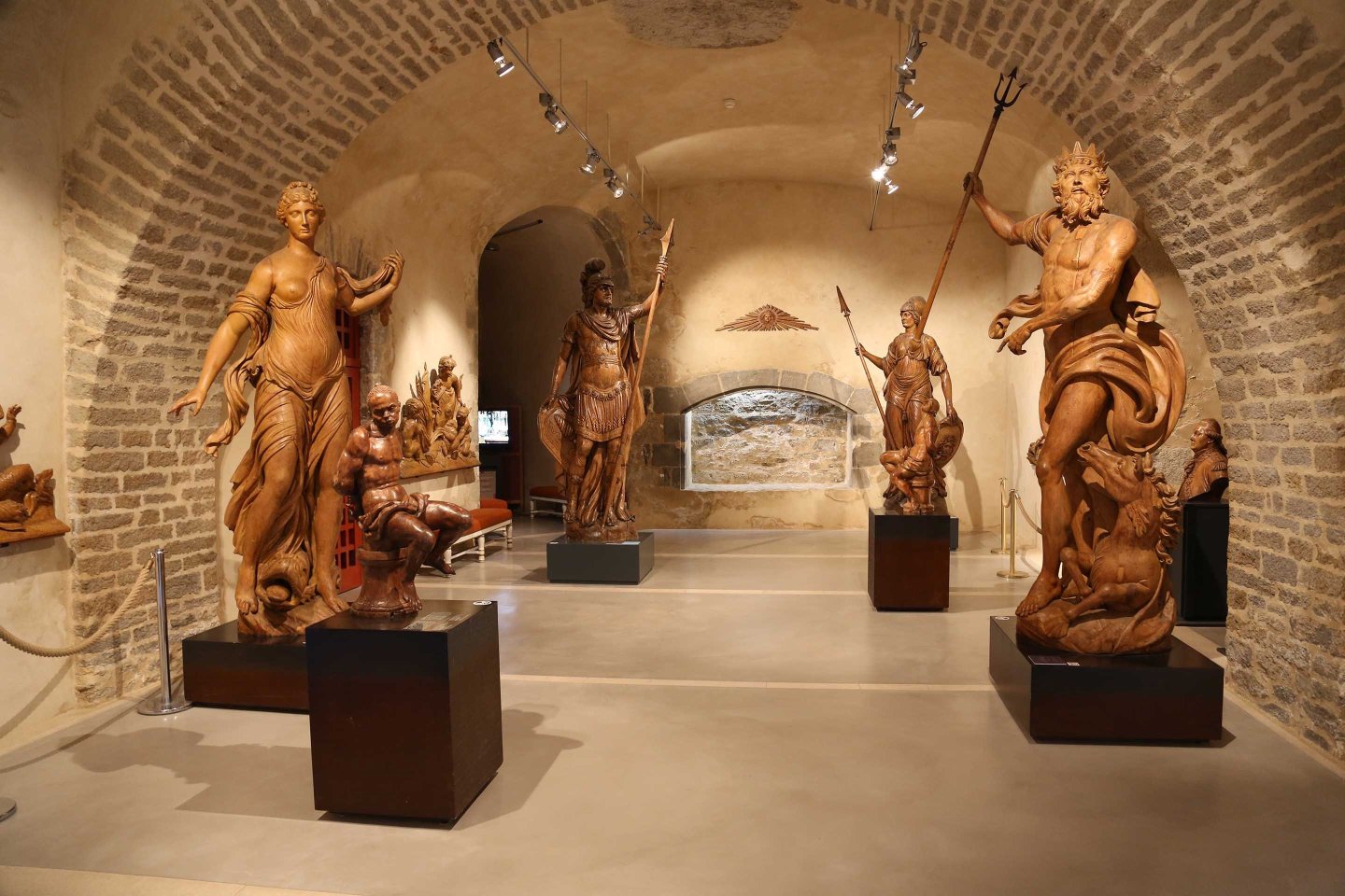
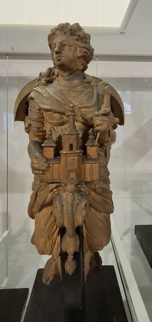
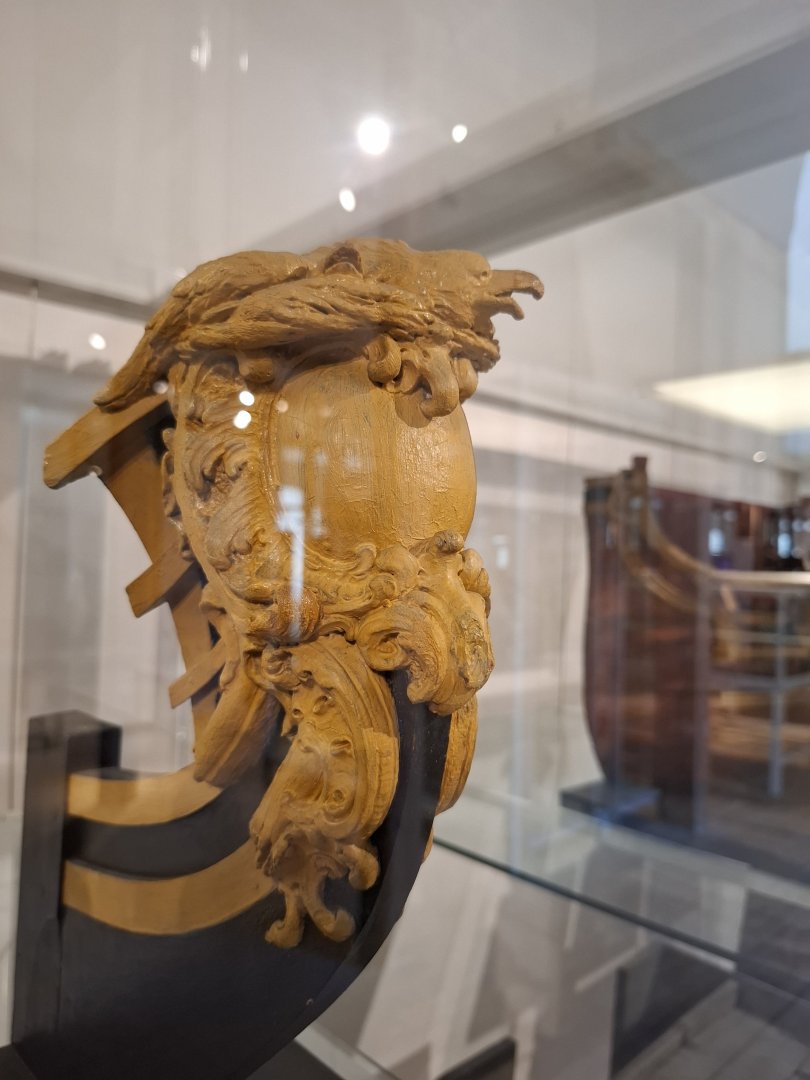
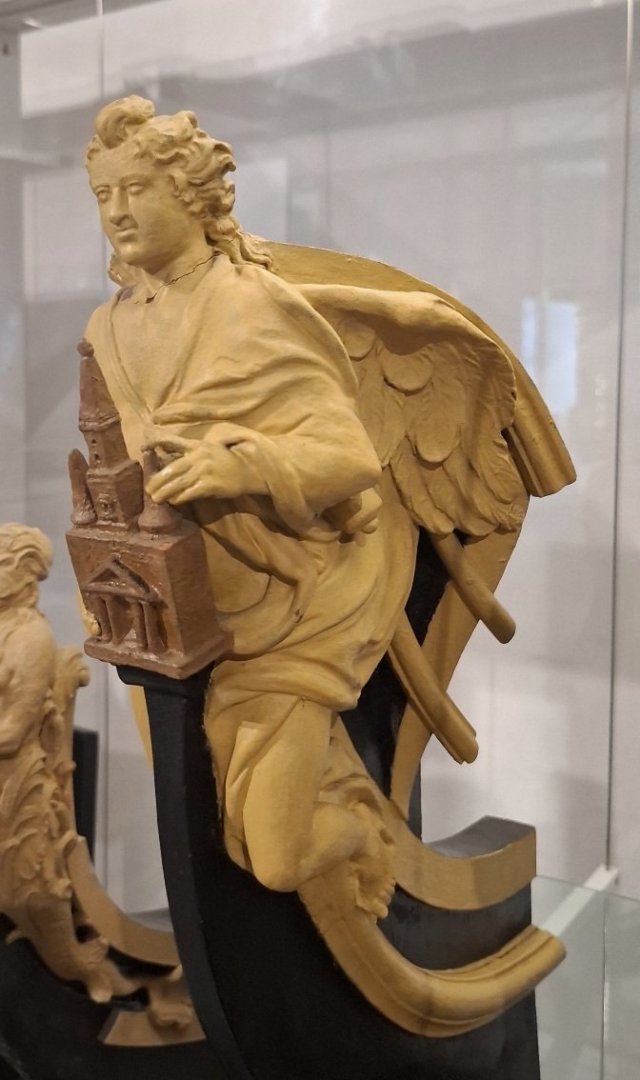
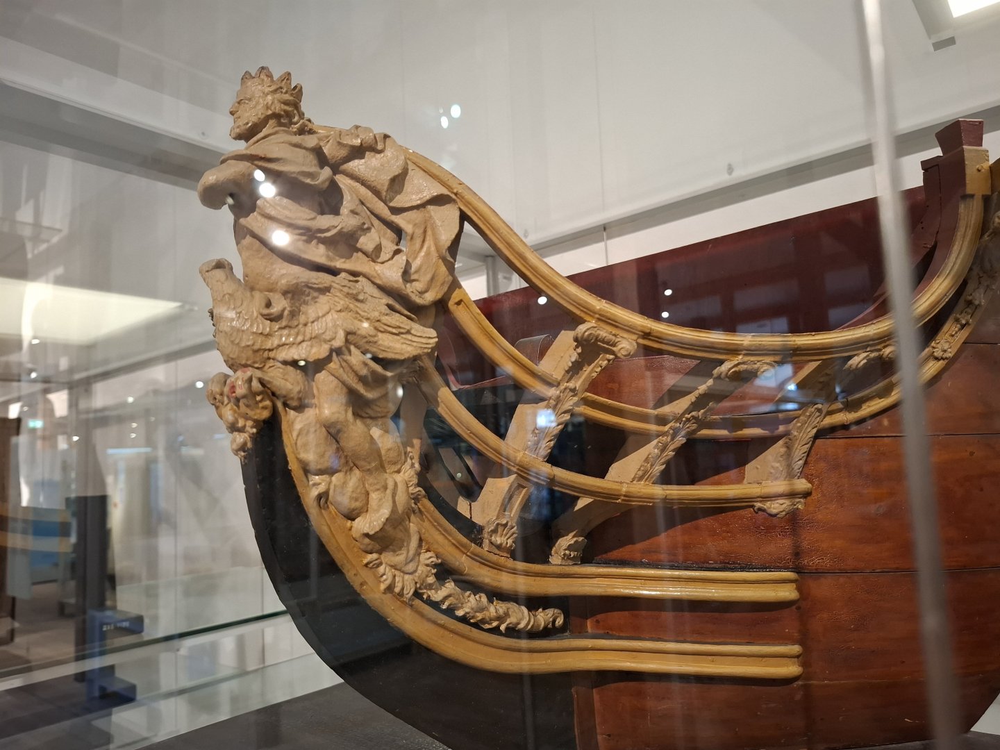
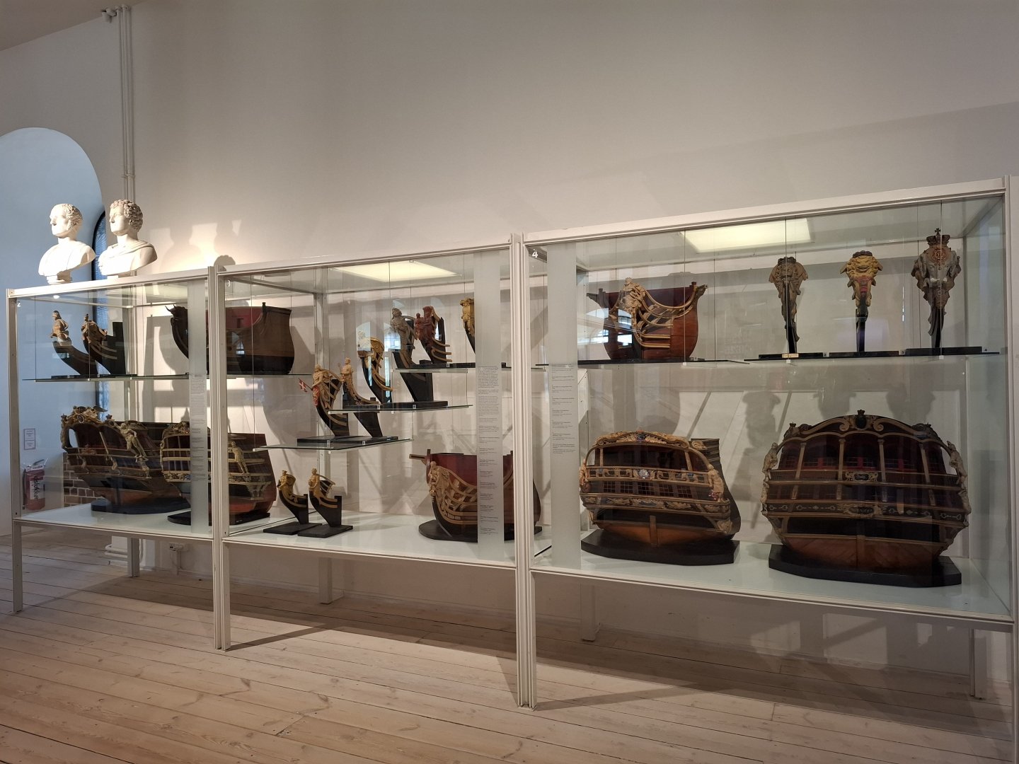
Hi Alexandr, the stern-model you can see at the krigsmuseet Kopenhagen, the wooden sculptures can be seen at the mussee de la marine at Brest in France. Here are more photos from Brest - wonderful collection by the way. and the Krigsmuseet at Kopenhagen, The stern-model I am building is at the very left side on the lower shelf. Concerning Erlachhof, I haven't been there. Is that in Austria, or in Germany? I don't know the museum. Matthias


-
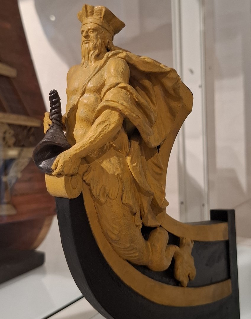
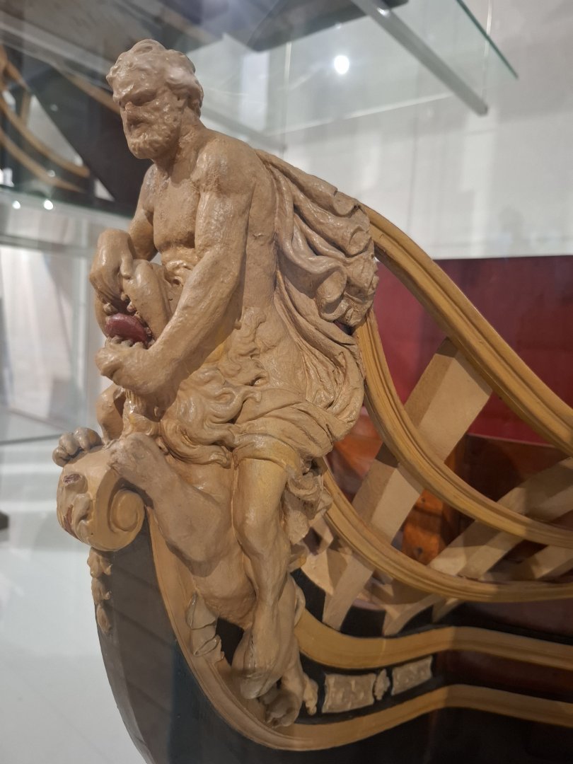
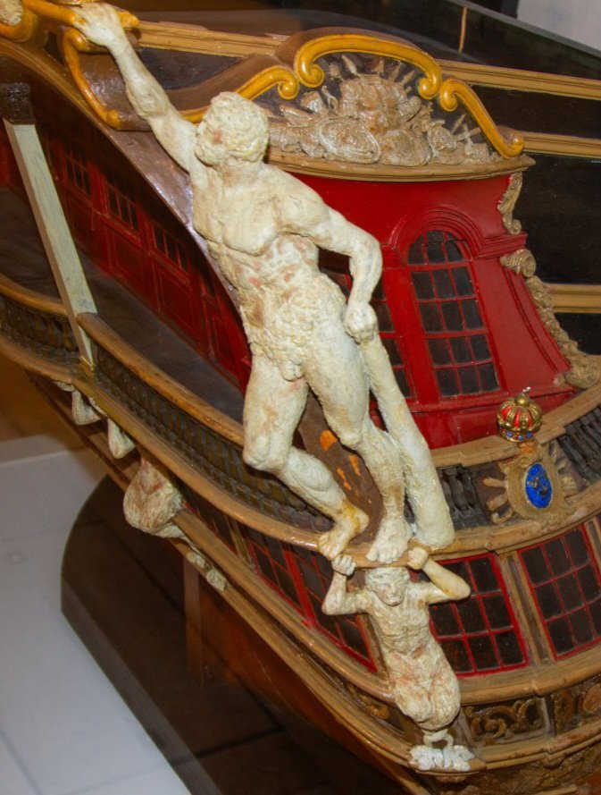
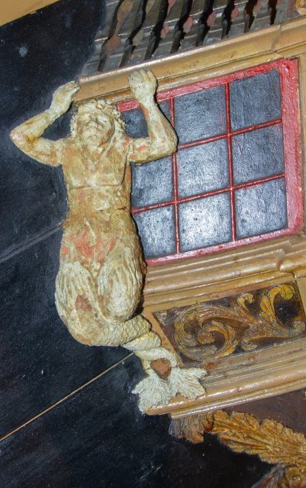
Hi Alexandr, I am going to use the Wax to make carving studies for the sculptures I want to make for my model. The posture of the figures are sometimes very twisted. I am just doing my first carvings, I have not much experimente in finding the proper body posture. I don't want to waste too much wood. The final Version will be boxwood like the other carvings. Here you see, what I mean. This model dates from 1748. The figures are made from wax. By the way, you were talking about the muscle armour of your figurehead. Here are two nice exampley from the Maritime Museum at Brest. Matthias


-
Hi Alexander, I am talking about easily moldable medium-hard modeling wax. Sculptors use this for the designing process. It is quite stiff, but when you warm it up a bit, or even just warm up your carving tools, you can very essily form it with precise details. You can also make it warm and form it around wire for better stability of arms or weapons etc. I bought myself some of it for designing the sculptures of my model, but did not try it out yet. Matthias