


ahb26
-
Posts
285 -
Joined
-
Last visited
Content Type
Profiles
Forums
Gallery
Events
Posts posted by ahb26
-
-
On 4/28/2017 at 5:11 PM, wefalck said:
... actually, I would have thought that the part is really U-shaped, or even slightly V-shaped - the position to which the stay will attach is not defined in the way it is modelled; the stay would in practice slip to one of the corners and then pull slightly sideways.
Good point. Here are Bails 2.0:
.jpg.c1bfe97162159f101fd3acf39bcb53bd.jpg)
Andrew
-
20 hours ago, JerseyCity Frankie said:
The structures the stays attach to are "bails" in my opinion, iron "u" shaped objects fixed with bolts through the top of the masthead, with the stays attached to the bow of the "u" on the centerline. This arrangement allows for the topmast to be struck without removing the stays (Spring stay? Triatic stay?) as the topmast is not part of that structure and can pass freely behind them.
Bails it is! Made from 22 gauge galvanized steel wire. All will be painted black in the end. Thanks to all for the input.
.jpg.b39d56e33d8a9c16e0f70b8dd5d392fb.jpg)
- JerseyCity Frankie, Eddie and BANYAN
-
 3
3
-
It is a Marine Models kit, but the plans are for the Joe Lane, not the Jeff Davis, which is of the same Campbell class (according to Chapelle) and has the same rig as the Joe Lane. In a further wrinkle, the Joe Lane plans are based on a survey taken after extensive repairs - in fact Joe Lane started out life as the Campbell (again, according to Chapelle) but was rechristened following the repairs.
-
2 hours ago, wefalck said:
Glad to see that my interpretations/guesses were correct. This arrangement with two back-stays and a sort of triatic stay running from the fore-mast top back down to the main-mast cap is rather intriguing. I don't remember having seen this before. It actually makes it impossible to have stay-sail running on the main top-mast stay.
I wondered about that. I still wonder about that!
-
Welfalck,
Perhaps this picture, with the various stays labeled, will clarify things:
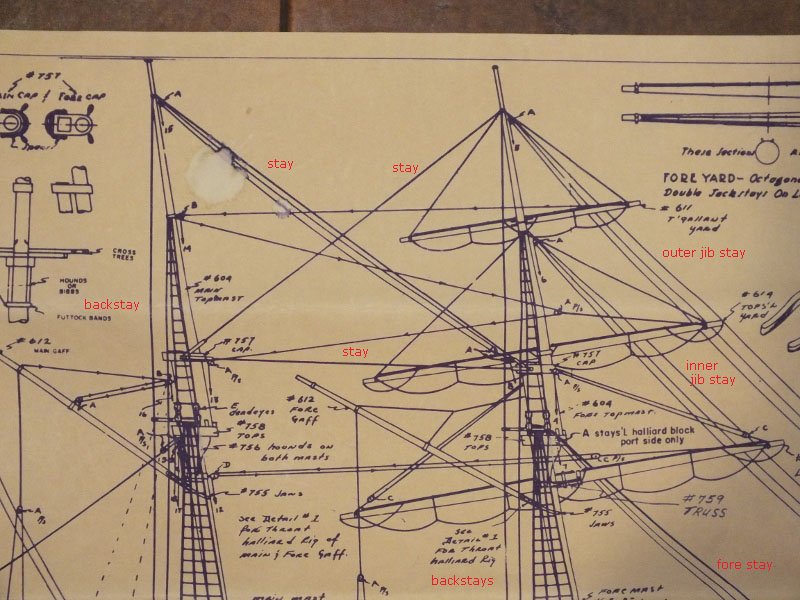
You are correct that the detail photo in my initial post is of the mainmast. Stays run from each cap to the top of the other mast, and between the caps. The Bluenose model photo on the Mastini book's cover shows a similar arrangement.
The Bluenose photo also shows the U-shaped fittings you described (the U has square corners) very much like what is in my plans. Thanks for your input on that!
Pat, the cast metal tops assemblies in the kit do have the V-shaped struts that you describe; you can make them out in side view in the photo. The backstays run through hooks on them. I think they're called spreaders, or are similar in function to spreaders.
Thanks to you both!
Andrew
-
Hi Mark,
I think you have identified my mystery component. In US Navy usage, it appears that "span" refers to a rope or iron arrangement that is fast on both ends and meant to hold something by its middle - which matches up well with my plans. I can run rope spans from eye bolts on the sides of the cap.
The Joe Lane is a relatively late (1850) design, so it's quite possible that the caps were made of iron. They are supplied as die cast metal parts in the kit, although that does not indicate that they were made of metal originally.
By the way, in looking for the naval definition of "span," I happened across the Historic Naval Ship Association (hnsa.org) and its on-line version of the 1891 Text-Book of Seamanship. I assume this resource is already well known in the modeling community. It looks like a real treasure-trove.
Again, my thanks!
Andrew
-
Thanks for the comments! Rick, I agree that the Marine Models kit is a quality proposition, although I don't have much to compare it with. The plans and instructions seemed daunting at first, but they rewarded careful study and forced me to educate myself about these ships rather than blindly following detailed steps.
I have spent the last few weeks going through all the rigging plans, writing up notes describing what attaches where, and digging through the Rigging section of this site. One great thing about this ship is that is has a little of everything: a square-rigged mast, a fore-and-aft rigged mast, various types of purchases and tackles, etc. I get exposure to a wide variety of rigging without having to do too much of any one thing.
I made up a spreadsheet for the running rigging, organized by belay pin, with block counts for each run. Then I looked at the blocks supplied with the kit. I am trying to restrict myself to using the contents of the kit, but the blocks aren't very good and I will replace them with blocks from Syren.
-
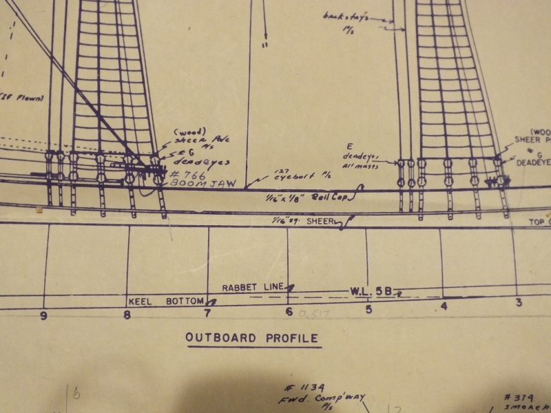
I am working on an inherited model of USRC "Joe Lane," my first ship model with significant rigging. The plans and instructions are pretty good but I am having trouble figuring out how to attach stays to the mast caps. The photo below shows two stays attaching to the mainmast cap via some long rectangular structures:
.jpg.a5af93b98fec12b7048986cd5bd6fcce.jpg)
The plan also includes a top view of the main and fore caps. There are thick horseshoe-shaped lines around the facing ends of the caps with an illegible label:
.jpg.ee5bc94881bb297ddaeb8fbf7ab16d7f.jpg)
I have a copy of Mastini's Ship Modeling Simplified, and the photo of a Bluenose model on the cover shows horseshoe-shaped fittings at the caps where stays are attached. However, the book itself does not describe these fittings. What are they?
Thanks for your assistance.
-
Thanks, Rick. I built one planked hull model (a small Friendship Sloop by Laughing Whale) many years ago, my only wood model before the Joe Lane. I enjoyed the planking process and I hope to do another.
I've stepped away from building to become completely familiar with the rigging before I start in. I go back and forth between the plans and Mastini's Ship Modeling Simplified until I understand every line's purpose and attachments, and I'm keeping notes as I go. This will take a while, because I have so much to learn. At least I can tell a halliard from a lift now. This will also allow me to figure out how many blocks of each size and type I need, so I can check them against what was supplied. I hope this exercise will save some tears later on.
-
I appreciate the comments, thanks! With the workspace more or less cleared, I laid out the spars against the plans. The yards, gaffs, topmasts and bowsprit are furnished tapered and cut to the correct length, with the exception of the topmasts, which seem to be much too long. The lower masts are simple 1/4" dowels.
.jpg.34d38b27f062ba56bca4ff15f945afc9.jpg)
The first step is to assemble the masts, using the supplied tops and caps and making sure that the other parts fit. I cut the square sections in the lower mast heads and topmast heels, cut and filed the flash out of the diecast tops and caps, and dry-fit it all together. Each mast has a fife rail and a ring of wedges, and the foremast has a truss for the lower yard.
.thumb.jpg.404e79e214cc242472a2cccb0a2afcec.jpg)
.jpg.2fe8460ea14ad8960705bc92903c3e5e.jpg)
I'll call that a good day's work. The masts and other spars still need sanding and staining along with myriad other operations, and the diecasts will need de-flashing and painting before final assembly. One thing at a time...
- Duanelaker, Shiphile, hexnut and 6 others
-
9
-
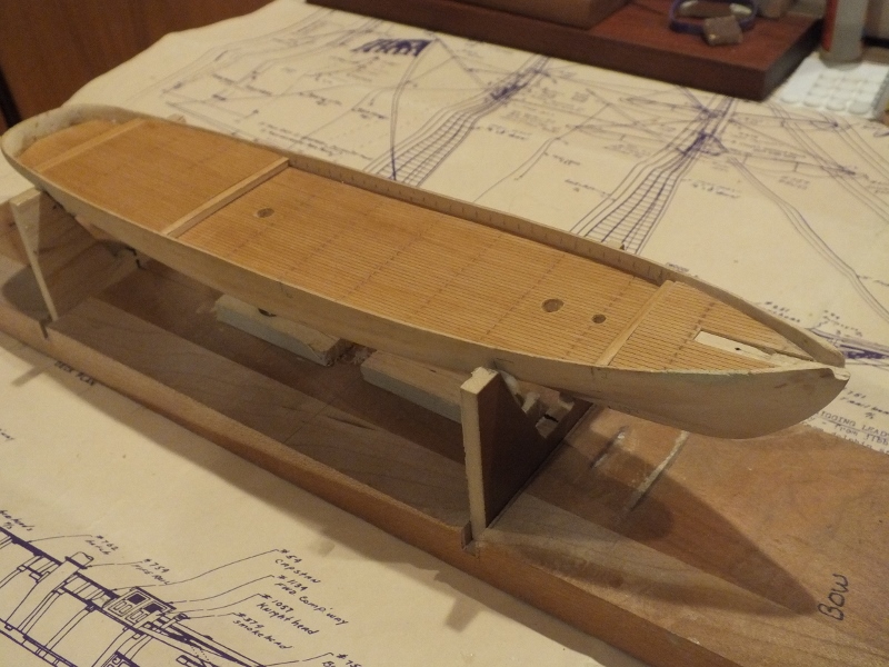
I have attached most of the major deck structures.
.jpg.32e07509b0d3bab4ad78911be76ef7e2.jpg)
The cockpit is pretty cramped. There wasn't as much space in the pre-carved hull as is shown on the plans.
.jpg.eefe6d7b528dafb64193cd3d9b1819f0.jpg)
In the bow, I was relieved to get the hawse lips into place without smearing glue all over the deck. The capstan goes in front of the mast but I haven't painted it yet. It is turned from brass, unlike most of the other metal fittings.
.jpg.d685c6e841c100377b8f07c0608a8fdd.jpg)
It's time to put the hull safely away for awhile and get acquainted with the spars and rigging. (The other ship is not a model I built; it was a gift, and when you hit a switch it plays "It's a Small World After All." Oh, the humanity...)
.jpg.209b560f88c21f32d828cc6830707495.jpg)
-
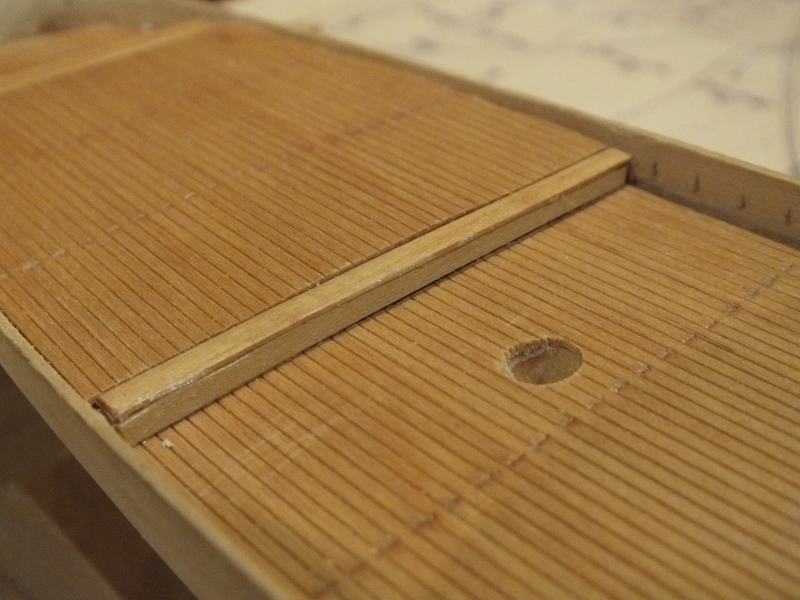
The plans show storage lockers along the rails of the raised aft deck, but provide no details. I built these from scratch, fitting each one to the curve and deck clearance on its side of the ship. Took me three tries to get two acceptable units. I used 1/32" basswood for the lid and front of each locker (top and bottom in the photo) and 1/16" for an internal gluing strip (middle).
.jpg.ccbcd29fc65e1b817280a1abca8bbab2.jpg)
Glued the gluing strip with about 3/32" clearance around the front and sides:
.jpg.0c03adcf99eb064cbd104179d6612e17.jpg)
with the addition of two small side pieces, the locker ready to finish and glue into place on the rail cap:
.jpg.36b5550ecdbebc05416f695fb20cc3ee.jpg)
To glue them in without the glue joint showing, I glued blocks to the inside of the front strip. The photo shows the locker upside down; the tape on the deck marks the edge of the front when the locker is in place. I ran three beads of CA glue on the deck where the blocks would end up, and a thin bead on the edge of the locker that bears on the cap rail, then slid the locker into place.
.jpg.c804b270100d81bb72ccb04a6e2b4df3.jpg)
.jpg.07c784946a201f7bae8c2f4165c96977.jpg)
The stain and varnish finish is probably not period correct, but I wanted something that would contrast with the rail caps and the deck, and I didn't want to use the gray that is used elsewhere.
.jpg.a968ea5a7e74c58e4c04392e5fbe57df.jpg)
- russ, coxswain, Duanelaker and 3 others
-
6
-
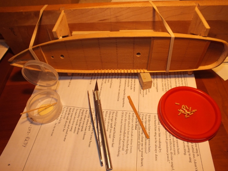
Time to work on the die cast deck structures. I don't know if they are made of Britannia metal or lead. I had to do a fair amount of filing and sanding to remove casting lines and sprues, and used steel wool on the light film of corrosion on some of the surfaces. I drilled the bases of the four solid houses (companionways and/or heads) and epoxied in cut-off nails to help secure them on the deck, then used a tape and template scheme to figure out where to drill the holes in the deck.
.jpg.8ffb18b94a2ecbf64d5e6ae0a16786a5.jpg)
I gave the pieces a light coat of etching primer, then painted with Tamiya acrylics.
.jpg.e9789aa376330102576b2d3fbe23f16b.jpg)
The color scheme described in the instructions is pretty drab, and I wanted to brighten things up a little. I looked through my wife's artist acrylics and came up with a red and a yellow:
.jpg.2d307974ef71f2fb2e4b728b6a533a44.jpg)
The macro lens really shows where I need to touch-up! I also made up what I call low-profile channels, 1/16" square strips notched to receive the chain plates, and glued them to the rail caps. Once the chain plates are installed, I'll glue 1/32" strips over the tops. I have no idea if these were used on this ship or any other ship; the instructions were mute.
.jpg.0556533745f735d6a8bcf91f585e852f.jpg)
I made the mistake of leaving masking tape on the top edge of the hull (see previous post) when I glued on the rail caps and these "channels". I intended to protect the paint on the hull from glue slopping over; instead, when I removed the tape, I found that the edges were glued the hull-rail cap joint in spots, and where I used CA glue, some had wicked between the hull and the tape and left its residue on the hull. I've managed to salvage the situation somewhat with careful sanding, scraping and repainting. Lesson learned!
- russ, Duanelaker, GrantGoodale and 6 others
-
9
-
I built chain plates and deadeyes using a technique suggested in the kit directions: strapping the deadeye with wire (supplied), soldering, then flattening the solder and drilling. It took some trial and error to get good results. This is a batch of 16 of the "large" (!) size, and the first of eight small ones ready to solder.
.jpg.7bd4230f0417cd32bff30b5eafc3a5e1.jpg)
I may redo some of the large ones. I also ordered paint (Tamiya acrylic), painted the rail caps, and glued them on. In process:
.jpg.5d9c395b15354c751af9ef8282f7cf37.jpg)
Taffrail area, with a cutout to accommodate the wheel house and spots to glue the benches. The unpainted areas over the raised deck are for future installation of lockers:
.jpg.1c7a147772436e7352e2acfee508933b.jpg)
Bow area, with gaps in the rail cap where the catheads go through:
.jpg.d62f4bcdfb1356b2421df872e48f23fe.jpg)
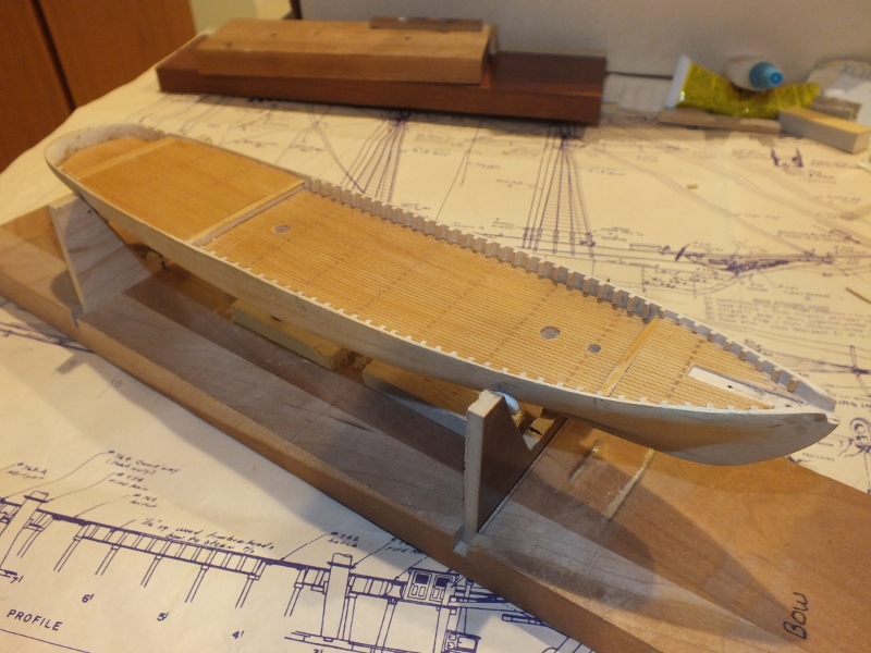
Two overall views. Unpainted parts of the outer edge of the rail caps are for future installation of rubbing strips (or low-profile channels).
.jpg.a148bc514d5a7245d2409302e975a003.jpg)
.jpg.5a76b76c532d0971a6ba9ad07620aa9f.jpg)
Getting the rail caps on opens up several areas for further progress, such as installing the deck structures that abut it. Hopefully, the pace will pick up now.
-
The kit came with two strips of 1/32"x1/8" wood that presumably were meant to form the rail caps, although the plans call for 1/16"x1/8" strips. In any case, I didn't care to bend straight strips to fit the curve of the hull (especially around the taffrail) so I bought a sheet of 1/16" basswood and traced the outline of the bulwarks onto it. I initially cut the rail caps on the wide side and all the way around the taffrail, and also cut a separate piece for the taffrail.
.jpg.4d2460cebfe29c20304c4af738604ee3.jpg)
Using the cutout in the basswood sheet as a guide, I cut the side rails and the taffrail section to form butt joints.
.jpg.6a746c0876b7f2ac2c2964c5b7e4bbea.jpg)
I narrowed the rail caps a bit and drilled the pin rail sections as indicated in the plans. These are ready for final sanding, painting, and installation.
.jpg.b6e4d32ae651edb2ceae3dee271c5694.jpg)
- coxswain, Duanelaker, EJ_L and 1 other
-
4
-
Since I don't have an air brush or ready access to modeling spray paint, I decided to use auto touch up paint, readily available down the street. The plan was to use sanding primer to identify and correct imperfections, then spray the copper and top of the hull. I found a color (Nissan Mist Orange) that, when dulled with 00 steel wool, worked well for copper, and I had satin black for the top on hand.
The primer went on well but I ran into a problem with the spray can: I could only get about 30 seconds of spray before it clogged. I had to use three cans to get three coats! (The auto parts store replaced one of the cans.) I think the clogs were in the cans, not the nozzle. No idea what went wrong, but it meant that I was limited in my ability to fix dings. The primer did wet-sand out very nicely.
.jpg.ab1b2057bcd38d2189ef38fef32b1bac.jpg)
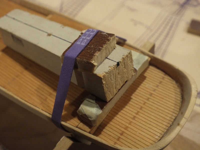
I made up a waterline marker (based on a plan in the Mastini book). It worked well but left some indentations in the soft primer.
.jpg.1b29467802a2a63277f14191f0ddd9df.jpg)
Masked off the top of the hull (the copper follows the waterline very closely) and sprayed the first coat of copper - oops! You'd think I'd have learned to use light coats by now...
.jpg.0b2a0391663efae8a7d56bd519a14cf6.jpg)
Sanded that out and proceeded with two more coats, dulled it with steel wool, and masked it off to spray black above the waterline.
.jpg.c3d1dcd5af2497dca8ea8e0df8ddf0e8.jpg)
With some trepidation, I removed the masking tape, and voila:
.jpg.f31a0fccce7f60e7d6f698496c16f8d9.jpg)
So, on to the rail cap and the chain plates and deadeyes.
- hexnut, Duanelaker, Fright and 7 others
-
10
-
I have made some progress in the month-plus since my last post. Gluing on the planksheer using carpenter's glue turned out to be easy with my wife taping as I applied the strip. I put a masking tape flag on one end of the strip so I could keep track of which side had glue applied.
.jpg.cb9a9610d630736eb649b94ed28ea4b4.jpg)
I notched the strip to accommodate the chain plates. The plans don't show any channels, so the chain plates lie directly against the hull.
.jpg.fdbff6985decb2a12987631f6714c12e.jpg)
I don't know if this detail is correct. The photo that came with the kit (of a scratch-built prototype, I believe) had channels, but a well-researched build I found on the web did not. I have seen plans that suggest a wale where the chain plates cross the cap rail, so I will add a strip there when the time comes.
Next step is painting the hull.
-
Is there a clever way to glue the plank sheer to the hull (see plan photo in previous post)? It is a 1/32" wood strip that runs the length of the hull (about 13") parallel to and about 1/2" below the top of the bulwarks. I've made tick marks along its path. The strip will lie against the curve of the hull easily; the challenge is to get a thin, even bead of glue on the length of the strip, and then get the strip in place before the glue dries. I might be able to go a few inches at a time, so that the glue doesn't have a chance to dry out before it's placed on the hull... I have a second pair of hands available if needed. Any recommendations? Thanks!
-
The timberheads are in. The raised section of deck toward the stern (the top of the cabin I suppose - is that the poop or quarterdeck?) does not have enough of the bulwarks showing above it for timberheads. The plans call for lockers in that area, anyway.
Next, I'll work on the hull exterior, smoothing, priming and painting. Before I prime, I have to glue on the planksheer (so called on Chapelle's plans, but labeled SHEER in the kit plans):
The plans call for 1/16" square strip, but the kit contains 1/32" square strips that seem to have no other purpose, so I'll use those.
- Duanelaker, Fright, Mirabell61 and 5 others
-
8
-
The planking is done - a lengthy, fiddly job. I tried carpenter's glue on a scrap of the planking sheet and as expected, it curled. I ended up using good old model airplane cement, which gave me enough time for positioning each piece and didn't curl the material.
The strips running athwartship are a workaround to some errors in laying out the panels. I've decided to live with little problems like this and do better next time, rather than reworking everything that isn't perfect.
The deck surfaces are slightly crowned. The panels followed the crown pretty easily, but I had to make up little fixtures to hold down the ends of the cross strips while the cement dried.
Next step is to cut and install the timberheads.
- Duanelaker, EJ_L, coxswain and 3 others
-
6
-
E.J.,
I blush to admit that the (solid) hull will not be planked, and I will use the scored wood sheet material supplied with the kit for the deck planking. The bulwarks were pre-carved in the hull but left thick; I've already thinned them to about 1/16". The decking sheet is scored lengthwise into 1/16" "planks" - I will see if I can devise a method of cross-scoring them to simulate offset planks of reasonable length. Some other questions regarding the sheet material:
- Is there any reason not to stain and varnish the decking before gluing it to the hull?
- The Marine Models instructions recommend not using a water-based glue to attach the sheet because it might result in warping. Is this an issue, and what alternative adhesive would be appropriate?
Thanks for your comments,
Andrew
- coxswain, Duanelaker, Archi and 1 other
-
4
-
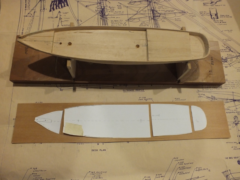
I've made some progress. I found a few sources of information about the Joe Lane. Chapelle's History of American Sailing Ships includes a chapter on revenue cutters, with a few pages, line drawings, and plans for the ship. The plans are very similar to those supplied with the kit, and both probably derive from the same set of plans maintained by the USCG.
I also located a number of photographs and descriptions of a handsome model scratch-built by Rex Stewart on the Marine Models solid hull. Mr. Stewart researched and included many details not included in the kit's plans.
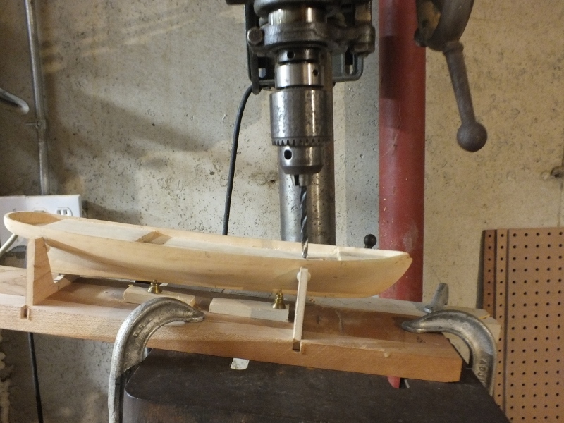
I put a good deal of time into research on building techniques, paint and so on. And I did some actual work: I constructed a cradle to hold the hull securely in a horizontal position, to assist with drilling, waterline marking, and other operations.
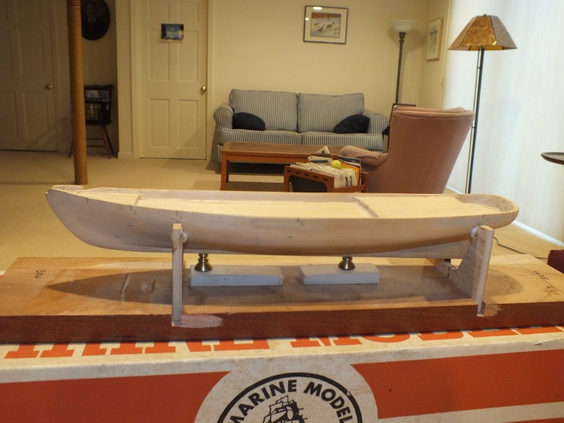
I set up my ancient drill press to the mast rake angle and drilled the hull:
This is the current state, with deck furnishings laid out (but not secured yet).
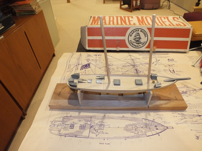
I think I will install the deck planking (scored sheet supplied with the kit) and timber heads before I finish the exterior of the hull. The rail cap and pin rails would be next, but I have to figure out how to do the pin rails first, since the plans don't provide useful details.
-
Russ: I hear you about the cats! We have two, and Kelly's brother may be the more likely to attack the rigging. I am a long way from having to worry about that, however.
Anja: I think I have to accumulate 10 posts before I can create a signature, but I will double-check and create it ASAP.
About the kit instructions: They are “General Construction Notes for Marine Model Kits.” The builder is meant to cross-reference the construction notes to the plan supplied with the kit, and ignore anything that doesn’t apply. The first few steps, in summary, are:
- Shape the hull according to the contours on the plan, cut out the rudder opening if necessary, fill and sand to a smooth finish. During this process, mark a longitudinal centerline around the entire hull.
- Trial fit exterior pieces (and clean casting flash from the die-cast pieces).
- Thin the bulwarks (which are left thick to avoid damage during shipping) to about 1/16”.
- Glue on wales, sheer moldings, and channels. (No wales or channels on the plans, but there is a sheer molding made of a 1/32” square wood strip.)
- Mark and shape openings in the hull sides. (There are few or none on the plans, a deficiency in my opinion – no scuppers, for example.)
- Make a cradle that holds the hull with the waterline horizontal to the base of the cradle, and secure the hull in the cradle using a long thin screw into the bottom of the hull.
- Temporarily fit the bowsprit (a diecast piece in this kit, with a wooden spar mounted on it).
- Drill mastholes to the proper rake, and other deck openings.
- Mark the waterline, using a block that rests on the cradle base and holds a pencil at the correct height.
I decided not to attempt to fair the hull according to the supplied contours: it’s good enough out of the box for my purposes. I have done some sanding and filling, and I probably have more to do – it’s hard to tell. I also thinned the bulwarks with an X-Acto knife and sandpaper, and experimented with some of the diecast fittings (including the bowsprit, which is located to the hull via two prongs in the casting, and the diecast trailboards). Gluing the ultra-thin sheer moldings to the hull will be an interesting challenge.
-
Many years ago, my niece’s father-in-law (now deceased) purchased this Marine Models “Joe Lane” for $37.50, made a start, and quickly abandoned it. The kit sat for a few decades until my niece and her husband passed it along to me after they saw me admiring a completed model they own. Here are the contents of the kit, along with Kelly, my overseer:
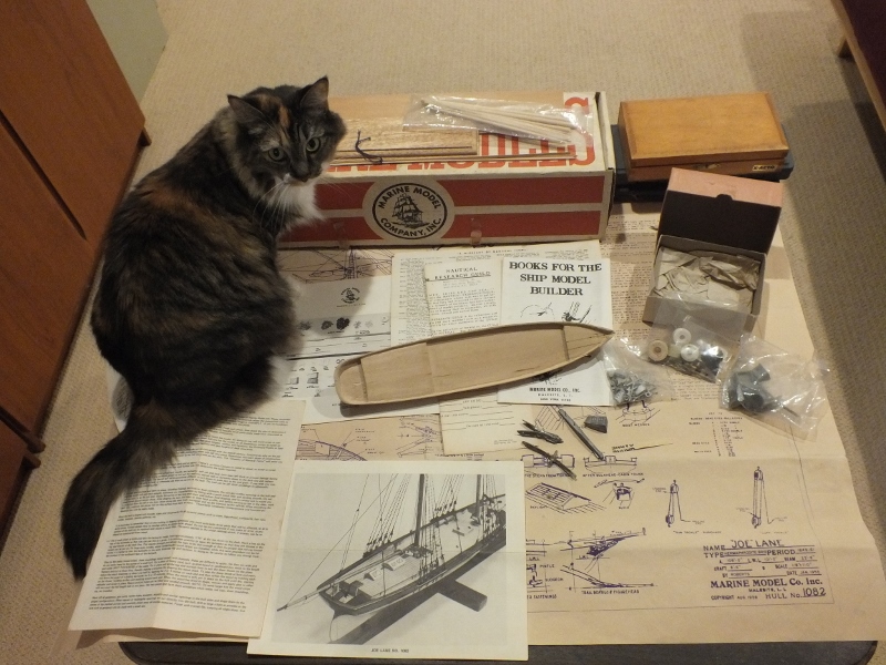
The kit consist of the hull, a full scale (1/8”:1’) plan, a set of generic instructions for building any Marine Models kit, a supplementary sheet with rigging and painting details specific to “Joe Lane”, a sheet of nautical terms, illustrations of what appears to be a prototype for the model, a sheet of planking, strip wood, spars, a base, a large number of diecast fittings, and rigging supplies.
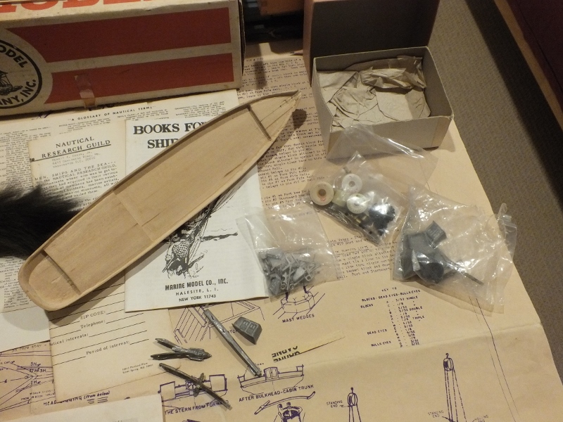
The original owner did some sanding and trial-fit the rudder to the hull. (He also knocked a chunk out of the taffrail, which I found in the bottom of the box and glued back into place.)
Since I have very little ship modeling experience, my goal for this kit is modest: I want to produce a model that pleases my eye and not worry too much about historic accuracy or ultimate detail. I’ll stay pretty much within the bounds of the kit and plans, and try to avoid scratch-building new components, at least to start out. I have a steep learning curve ahead of me and I expect I will spend as much time planning and researching techniques as I do building. I’m looking forward to making full use of this site and its members’ wisdom.
- Robin Lous, EJ_L, mtaylor and 7 others
-
10
.jpg.b1d495763bddc7d841414bbc3c7dc725.jpg)
Joe Lane by ahb26 (Andrew Bodge) - FINISHED - Marine Model Company - Scale 1/8”=1’ - Revenue Cutter - Inherited kit, novice modeler
in - Kit build logs for subjects built from 1801 - 1850
Posted
I am almost embarrassed to ask, but how the heck does one strap (or strop) a block? My efforts so far have not worked. I am using the sewing thread that came with the kit, and one of the 3/32" blocks from Syren, for my trials. I have the block rather tenuously anchored to a board using a thin wire through one of the reeve holes. I tried tying a loop in the thread, passing the loop through a thin tube, pulling the loop tight around the block, and tying a lighter thread around the loop at the end of the block to secure it - that didn't hold tight enough to get glue on it. I tried tying an overhand knot in the thread, dropping the loop around the block, and pulling it tight, but I couldn't get the knot where it belonged.
Part of the problem is that the block doesn't hold still; it pivots around the wire and rides up and down it. A second wire might help. Also, the thread is springy and perhaps a bit slippery. I could try the lighter-weight thread from the kit. But whatever I do, it seems like a very fiddly business with these tiny blocks and my fat fingers. Obviously, modelers figure out how to do this or they would go insane trying, but I sure could use a tutorial, and I haven't found anything like one on this site.
Thanks for your help in preserving my sanity!
Andrew