michaelpsutton2
-
Posts
841 -
Joined
-
Last visited
Content Type
Profiles
Forums
Gallery
Events
Everything posted by michaelpsutton2
-

Making sails for HMS Victory
michaelpsutton2 replied to rafterrat_2005's topic in Masting, rigging and sails
I recently borrowed this book from the library. Period ship Modeling: an illustrated masterclass: the Building of the American Privateer Prince de Neufchatel by Phillip Reed. In it he shows how to make remarkable small scale sails from tissue dipped in diluted paint. -
What a great pic!
-
Copper plated ships in NMM
michaelpsutton2 replied to Gaetan Bordeleau's topic in Nautical/Naval History
Try these links for pic's of weathered copper: http://www.modelexpo-online.com/album.asp?a=Thomsen_USS-Constitution http://cs.finescale.com/fsm/modeling_subjects/f/7/t/68621.aspx?sort=DESC -
The phantom model is on my shelf as the next project. I am saving this thread as an inspiration
- 139 replies
-
- 1
-

-
- phantom
- model shipways
- (and 1 more)
-
I always thought the shrouds themselves were "wormed parcelled, served & tarred". Particularly on vessels with larger diameter rigging. The ratlines were left natural.
-
As I said in my own review a fine book and a welcome addition to my shelf. I will positively purchase any future volume in the series. So many other books seemed focused on the larger units of the fleet. It would have been nice if there had been at least one example of the "brigantine rig" in the chapter on masting and sail plans. Also the tables of spar dimensions that were calculated by the author from Steel were at best put in the next volume and at worst unnecessary as anyone could generate those for him or herself. As always I wish that the plans did not straddle the gutter between pages.
-
Constitution. Mystery rigging in top
michaelpsutton2 replied to JerseyCity Frankie's topic in Masting, rigging and sails
Interesting! I have emailed the Constitution Museum. I will let you know what they have to say. -
If you are going to have the cannon on the man deck . You might consider a small rack against the bulkwarks between the guns with 3 or 4 shot in each one. But no more than that. I think it highly unlikely that there were shot garlands around the deck structures such as are found on Naval vessels. I don't think that the Bounty's carriage guns were ever fired except as signals.
-
scroll saw troubles
michaelpsutton2 replied to michaelpsutton2's topic in Modeling tools and Workshop Equipment
He was talking about the spiral blade. He claims that he has more control than with straight blades. He does say that the spiral blades remove moe material so that you have to be more aware of what side of the lines you cut to. -
Its true, one picture is worth a thousand words Thanks all
-
They are set at a radius to the keel when viewed from either above or below right?
-
A pox on me for a knave...it is of course perpendicular. Are the frames usually perpendicular to the keel (I have learned not to say "always") even when there is a lot of drag aft such as in a cutter or schooner? What about the cant frames up in the eyes of the bow. Are they still perpendicular when viewed athwartship? I confess never to have done a true plank on frame
-
Model Expo's parts picker
michaelpsutton2 replied to Don Quixote's topic in Modeling tools and Workshop Equipment
The hard part is to let go of a part cleanly without disturbing it's location. It seems like one or the other of the feelers is always puching to one side on the release. It's another one of those cursed things that needs practice The nice thing is that you can pass the holder through the model or from one hand to the other without losing hold of the part. Like a hemostat without the big loops on the back end -
Are the timber heads on the foc'sle parallel to the keel, the waterline or the sheer?
-
scroll saw troubles
michaelpsutton2 replied to michaelpsutton2's topic in Modeling tools and Workshop Equipment
My brother-in-law is a great wood worker and a fair model builder. He told me he always uses the round blades with the teeth all the way around the blade. Any other opinions? -
scroll saw troubles
michaelpsutton2 replied to michaelpsutton2's topic in Modeling tools and Workshop Equipment
OK then, under the eternal law that of no good deed shall go unpunished... How do you properly tension the blade? -
I have a Craftsman scroll saw. It always want to curve the cut around to the right. Last night I was cutting 3/8" plexiglass for a stand and I was feeding the piece in at almost 30 degrees to the direction of the cut. I have measured the angle of the blade and it is true. I have held a piece of steel against the side of the blade, turned on the saw and could not feel any "wobble or twist". Is there some kind of adjustment or is it me?
-
Some might disagree with me...but when deciding what size line to use or for that matter to make, round down rather than up. It is better to have the rigging a tiny bit light instead of too heavy.
-
Part of the issue is that the thickness of the bulwarks limited the amount of movement possible of the oars unless the port was bigger than the shaft
-
Calculating the length of topgallant yards
michaelpsutton2 replied to michaelpsutton2's topic in Masting, rigging and sails
Last night I found a 1794 copy of Steel on the Historic Naval Ships Association websitehttp://hnsa.org/doc/steel/index.htm%C2'> . It said: PROPORTIONAL LENGTHS OF YARDS, IN THE ROYAL NAVY. Main-yard, 8/9 of the main-mast. Fore-yard, 7/8 of the main-yard. Mizen-yard, 6/7 of the main-yard. Main-topsail-yard, 5/7 of the main-yard. Fore-topsail-yard, 7/8 of the main-topsail-yard. Mizen-topsail-yard, 2/3 the main-topsail-yard. Topgallant-yards to 74 gun ships, 2/3 all under, 3/5, of their topsail-yards. Royal-yards, 1/2 of the topsail-yards. Cross-jack-yard, the same as the fore-topsail-yard. Spritsail-yard, the same as the fore-topsail-yard. Spritsail-topsail-yard, the same as the fore-top-gallant-yard. Studdingsail-yards, 4/7 of their booms. Driver-yard, the same as the fore-topgallant-yard This is different than my copy! And certainly different than Lee. It works much better. And lastly in the section on rigs and sail plans in Sloop of War, the author comments that it is almost impossible to determine with any certainty what the rig of a small vessel may have been. He says the brigs, sloops, snows and brigantines were re-rigged and re-rigged. Further he comments that although many 18th century small craft are recorded as brigantines, not a single set of spar lengths for a brigantine have come to light. It is only in the 19th century that there is documentary evidence for this rig. -
Calculating the length of topgallant yards
michaelpsutton2 replied to michaelpsutton2's topic in Masting, rigging and sails
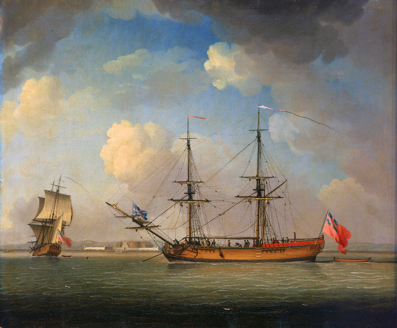
I agree that in there were differences between the theory of masting and what you would find if you could visit the harbor. But what I am seeing is that while most of the masts and other yards seemed to follow the rules in most cases, the topgallant yard lengths listed for specific ship never and i mean never followed the rule. The sail plan I am attempting to reconstruct would be for the Port Antonio purchased into the Royal navy about 1757. She was two masted. The placement of the masts is not suitable for a ketch, and the arrangement of the lower dead-eyes indicates she was a brig or snow and not a schooner of some kind. Given the date I think a snow more likely. I have incuded a paining by Clevely from 1759 of a what appears to be a similar vessel. Just add a handful of gunports in the waist and some sweep ports as well. She was 67'9" on the deck 22' beam, 9'9" deep and 144 tons. L+B+D =99'6" divided by 2 gives a main mast length of 50' which matches nicely with Steel and the other examples given the "Sloop of War". Lee's book does not have much to say about two masted ships. The main yard is .9 times the mainmast 45' and we are still good. The topsail yard is about .72 of the main yard or about 32'5". This figure is supported by all of the tables, If the top-gallant should be 1/2 the topsail then we would use 16' or a couple of inches more. But look at the figures in Steels examples. His brig has a main yard of 42', close, a topsail yard of 31'6", still very close... and a top-gallant of 23'6" which is a full 34% bigger than his own guidelines would indicate.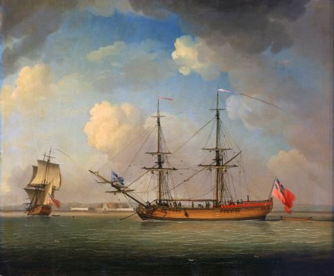
-
Calculating the length of topgallant yards
michaelpsutton2 replied to michaelpsutton2's topic in Masting, rigging and sails
That's my point exactly!!! Every source more or less says 1/2. Now look at the Appendix II in Lee or the" Dimensions of Masts and Yards of the Royal Navy" on page 53 of the 1794 edition of Steel. The 100 gun ship in Steel has a main topsail yard of 73' & a topgallant of 48'9"38 that's a lot more than 1/2 it's a little more than 2/3. The 38 gun ship is 59 & 37. In Lee the avg for the 1773 Establishment on page 198 is .656 on the main & .6632 on the fore. in the 1745 & 1754 establishments table it is .69 on the fore & main. Not a single example of a real ship has topgallant yards any smaller than .6 My question is why don't the table reflect the formulas. If I use the formulas I come up with very different results Should I use the ratios as described in the text or in the examples? -
Maybe you guys could offer an opinion or an explanation. Both Steel's “Elements of Mastmaiking, Sailmaking & Rigging” as well as Lee's “The Masting & Rigging of English Ships of War” indicate that for most if not all of the 1700's, topgallant yards are to be ½ of their respective topsail yards. Easy enough but....... If you consult the tables of contemporary dimensions in either book the proportions shown in all of the examples range from .625 to as much as .74. I have just rec'd my copy of Ian MCLaughlan's “Sloops of War” He devotes a whole a section in the back to the various sailplans. In it he gives 6-8 lists of spars for various sloops from the late 1600's through about 1750. The proportion of topgallant yards to topsail yards in the lists is pretty constant at about .7 But then he gives a list of proportions to be used to calculate the lengths if you cannot find an actual list for a specific vessel. His list of proportions recommends .5 which is not in line with the lists of actual spars he has on the same page. This creates quite a difference in the look of the sailplan. It becomes so much squarer at the top. It's not a huge visual issue with bare yards, but when the sails are bent on it becomes a brand new day. What am I missing?
-
It's amazing to see the transformation of the rough materials. The final level of finish is simply wonderful.
-
When I got the used one it looked new