hamilton
-
Posts
1,933 -
Joined
-
Last visited
Content Type
Profiles
Forums
Gallery
Events
Everything posted by hamilton
-

British Pathe film: Model Boat Building, 1956.
hamilton replied to uss frolick's topic in Nautical/Naval History
I had a colleague once who decided to build a boat in his back yard. Problem was, once it was done he realised there was no room to actually get it out, so he had to rent a crane to lift it over his house and onto the street! Maybe the modeller featured in the image above built a scale crane to help him with those monsters! hamilton -
Hello Gaz Great start on the Peregrine. I believe this kit was released at around the same time as the Corel Greyhound and Eagle kits. My experience with the Greyhound was that it was a very challenging model with a great number of flaws in the design. But from what I see here these same problems don't seem to be at issue with the Peregrine! You'll find that there are few kits that have pre-cut rabbets - this is something that you either have to cut in yourself or that is created by narrowing the false keel and attaching separate keel, sternpost and stem parts. Corel's practice seems to be to provide a centre keel piece that includes the keel, so the bearding and rabbet lines must be traced from the plans and the rabbet joint carved out - this can be challenging on the smaller scale kits and especially since the ply used by Corel is not of the best quality - more like pressboard with thin veneers on either side. But you are doing a great job with these elements and it'll be nice to see the model shaping up. hamilton
-
Thanks Druxey! We'll see how the rest of them go......frame 1 F/A is on the go now and hope to finish on the weekend....been fun so far hamilton
-
Thanks very much Jaager - and sorry for being ambiguous earlier. hamilton
-
Thanks Jaager and David - and sorry Jaager for the ambiguity - I did not have that info on hand - it is the Echo of 1781 - but I suppose that's immaterial now! hamilton
-
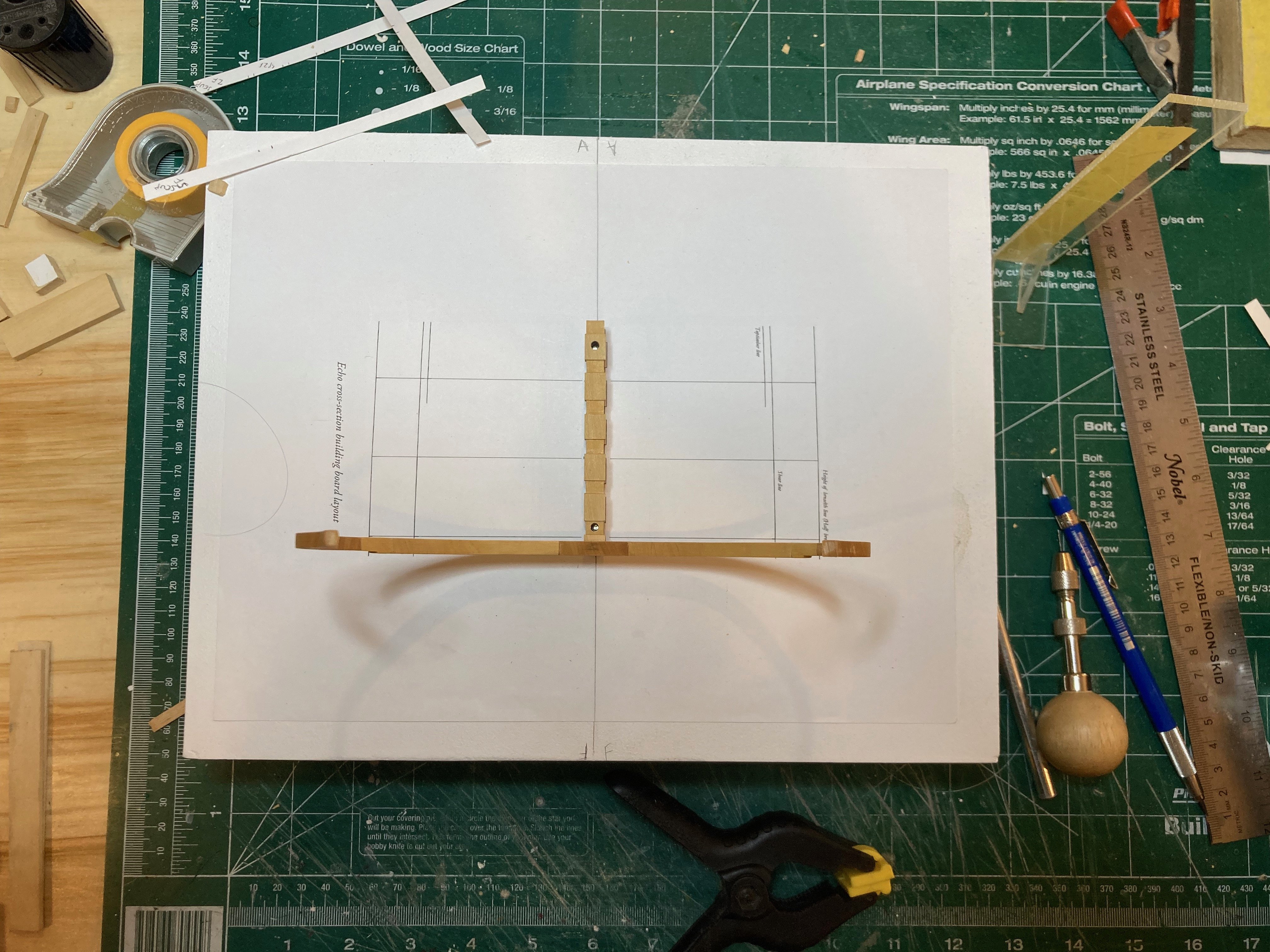
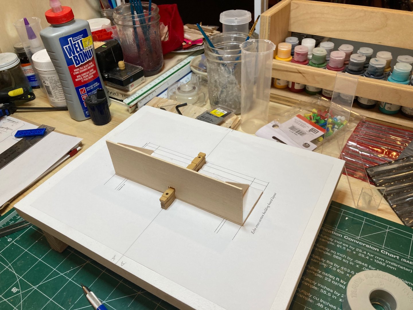
Hi there: Working on Echo cross-section and wondering about the size.arrangement of bolts that would have been used to fasten the square frames to the rising wood/keel. hamilton
-
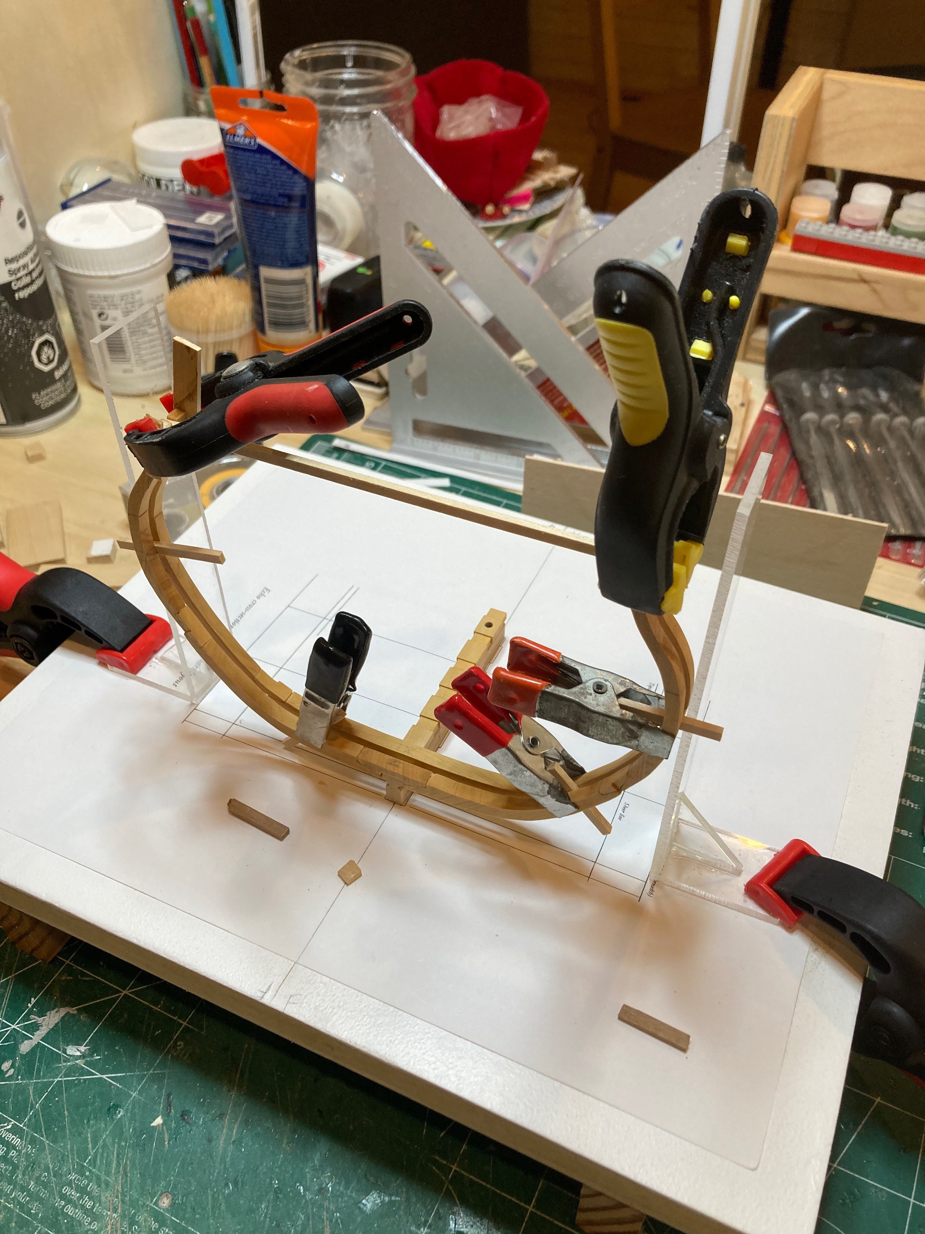
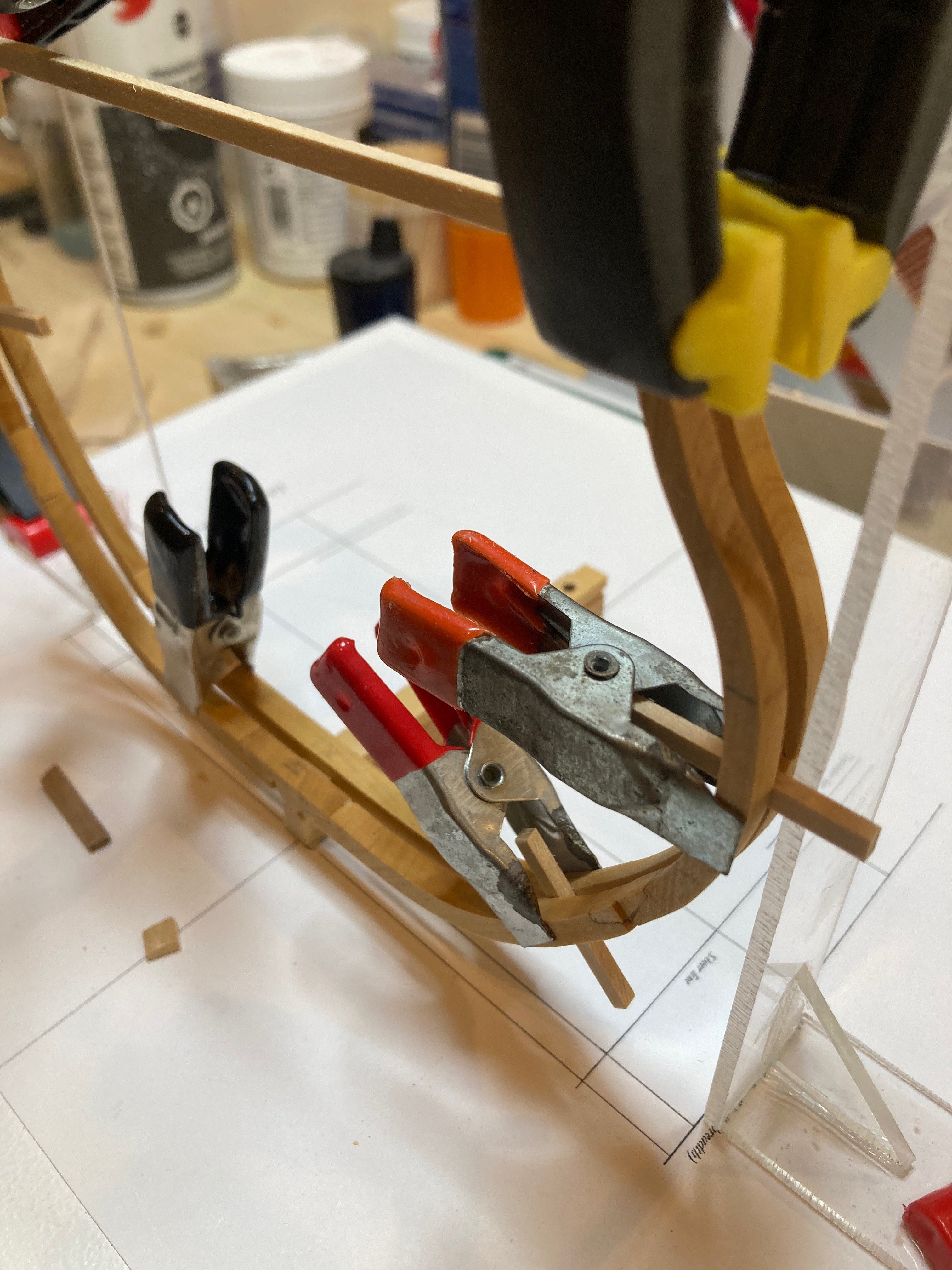
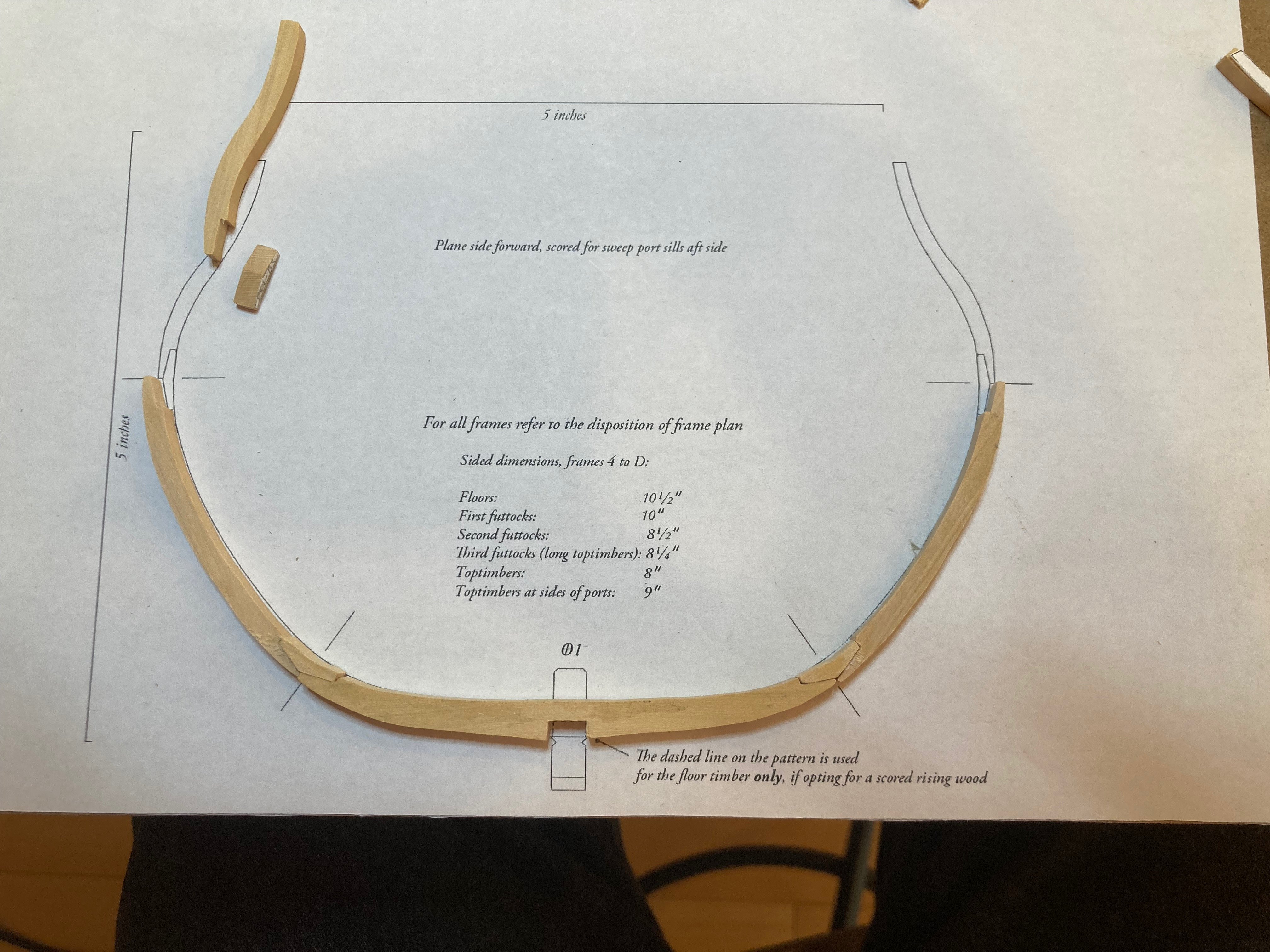
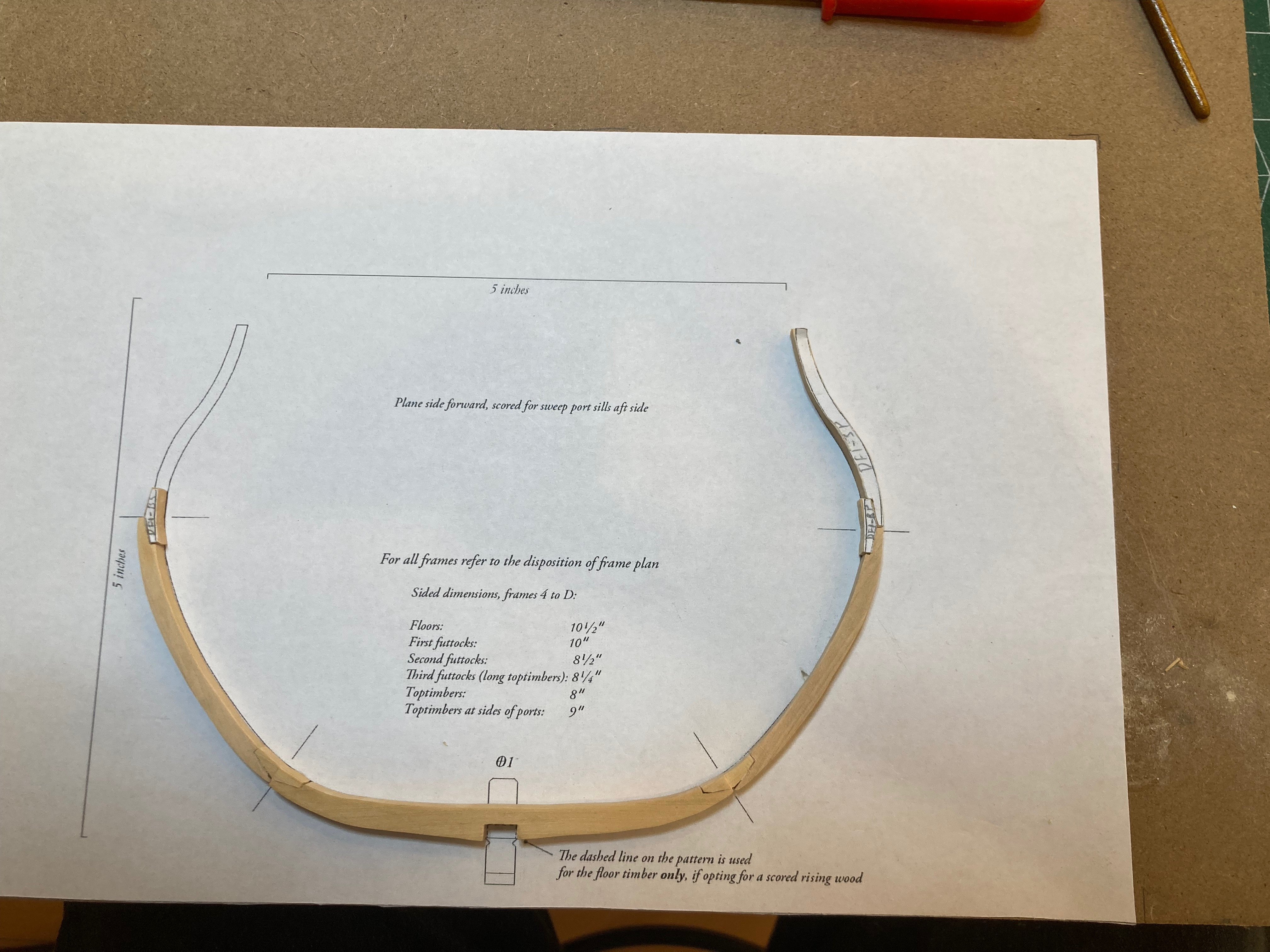
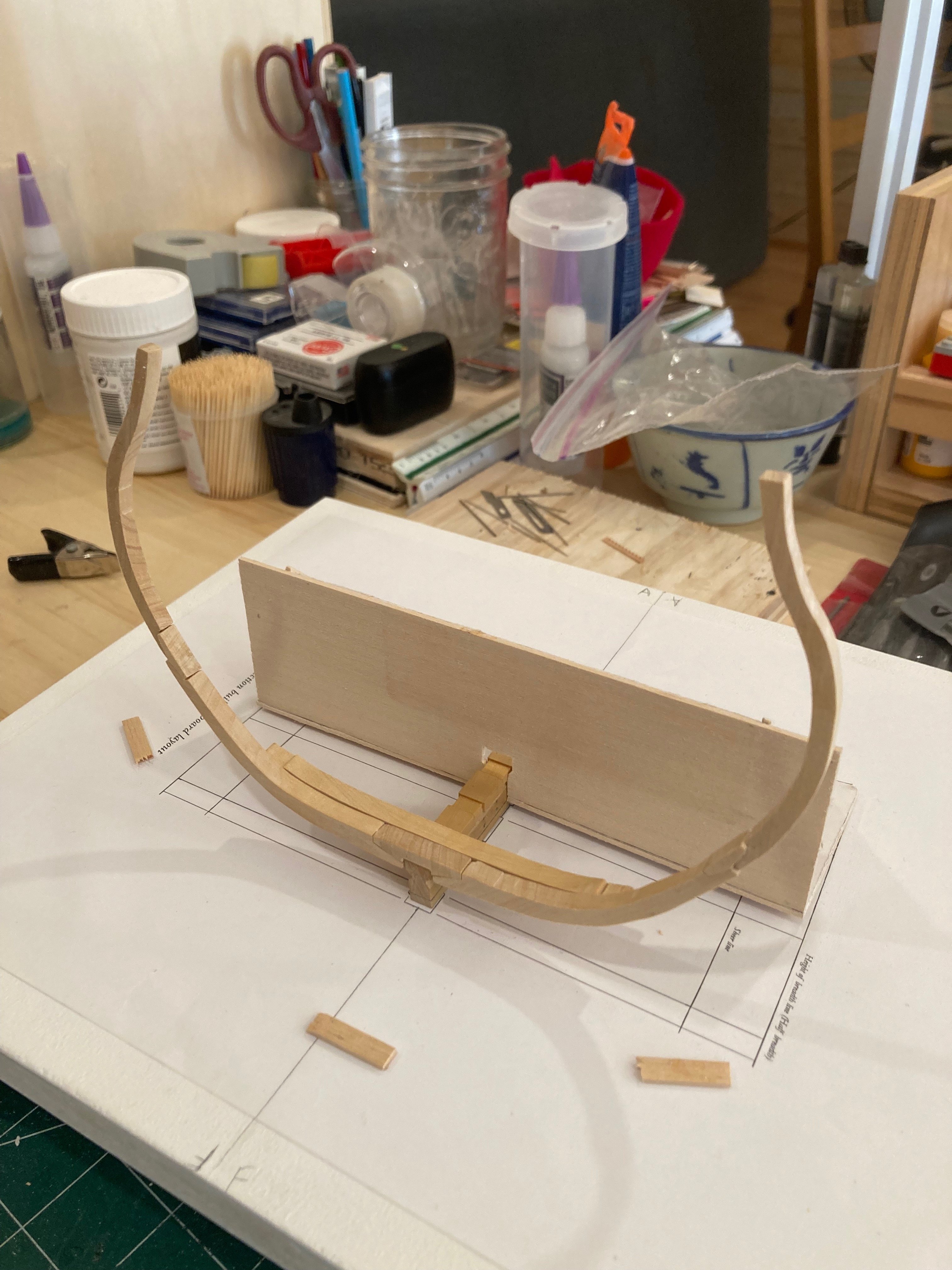
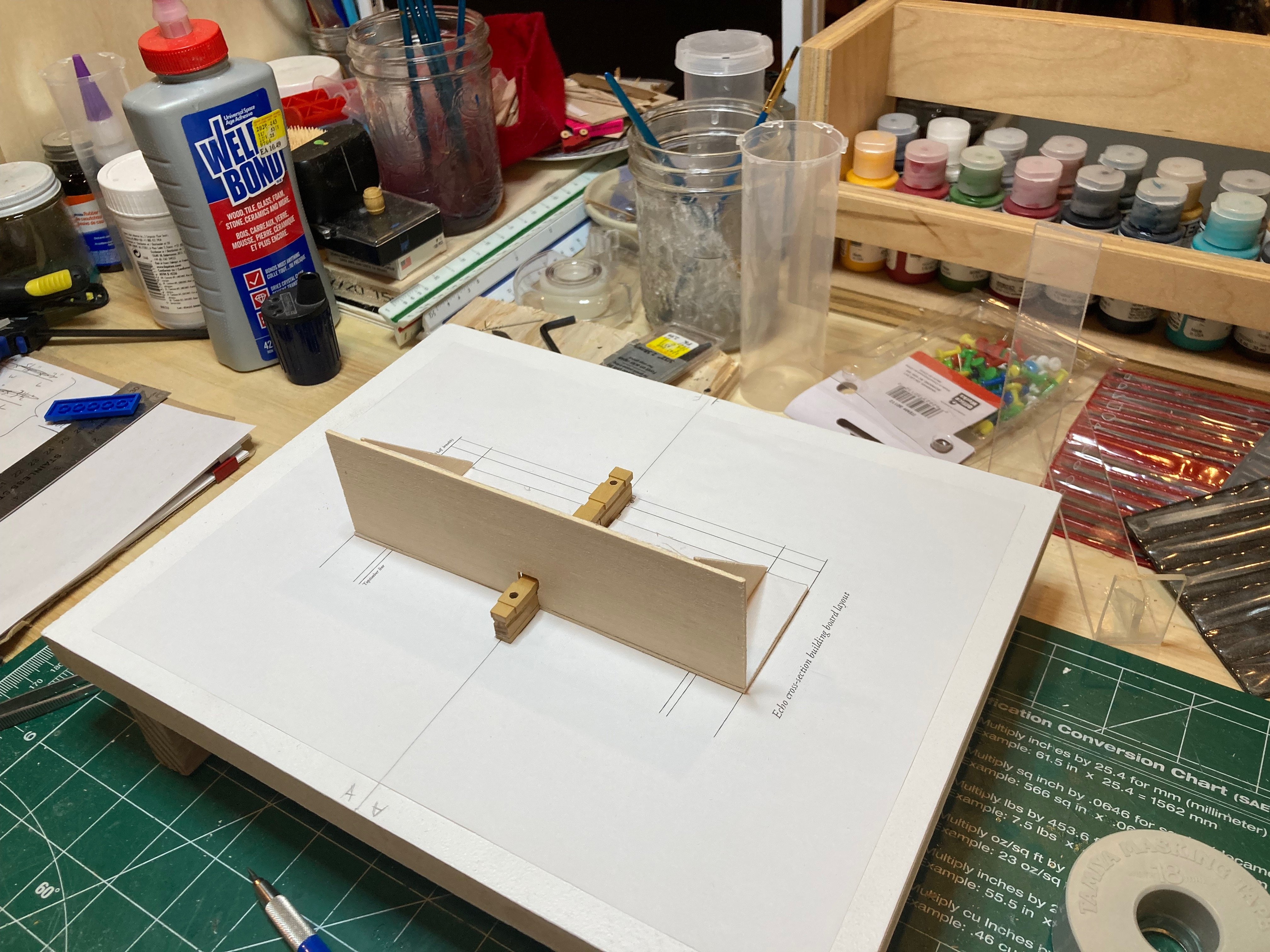
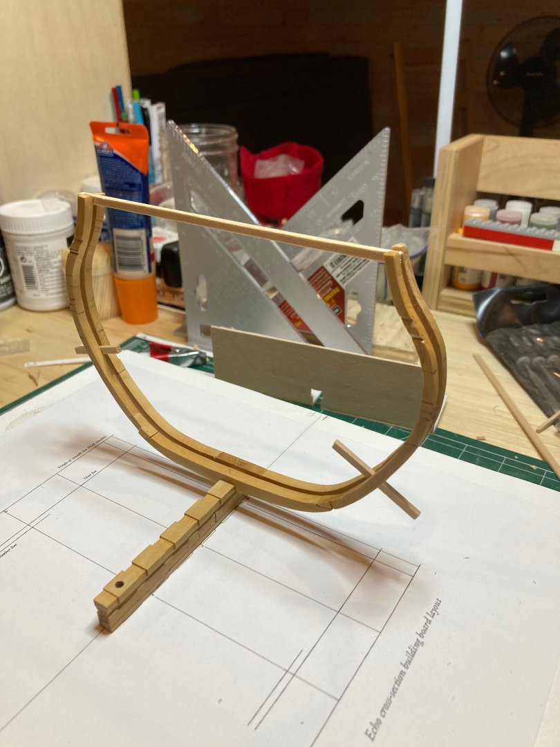
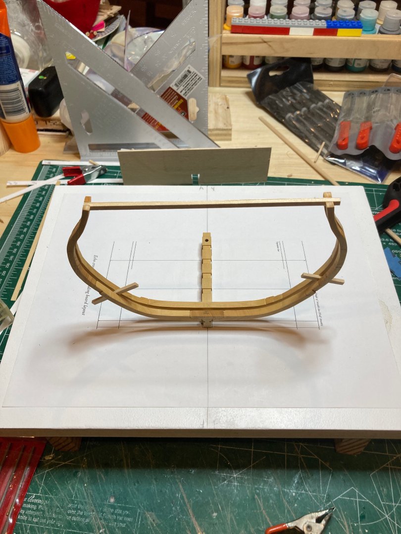
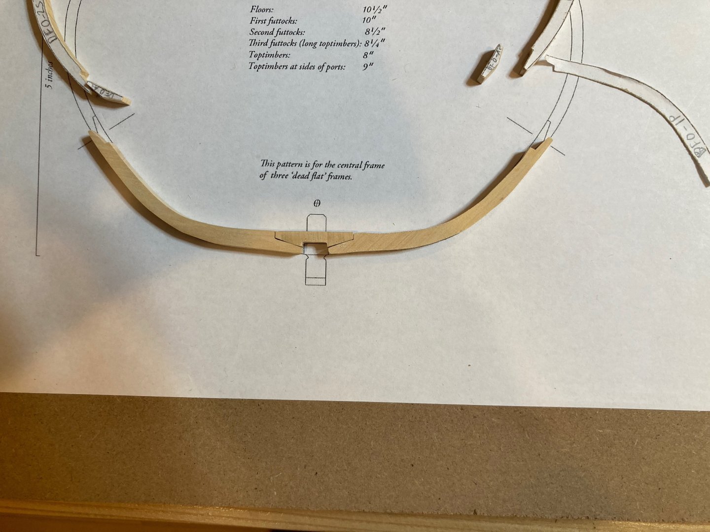
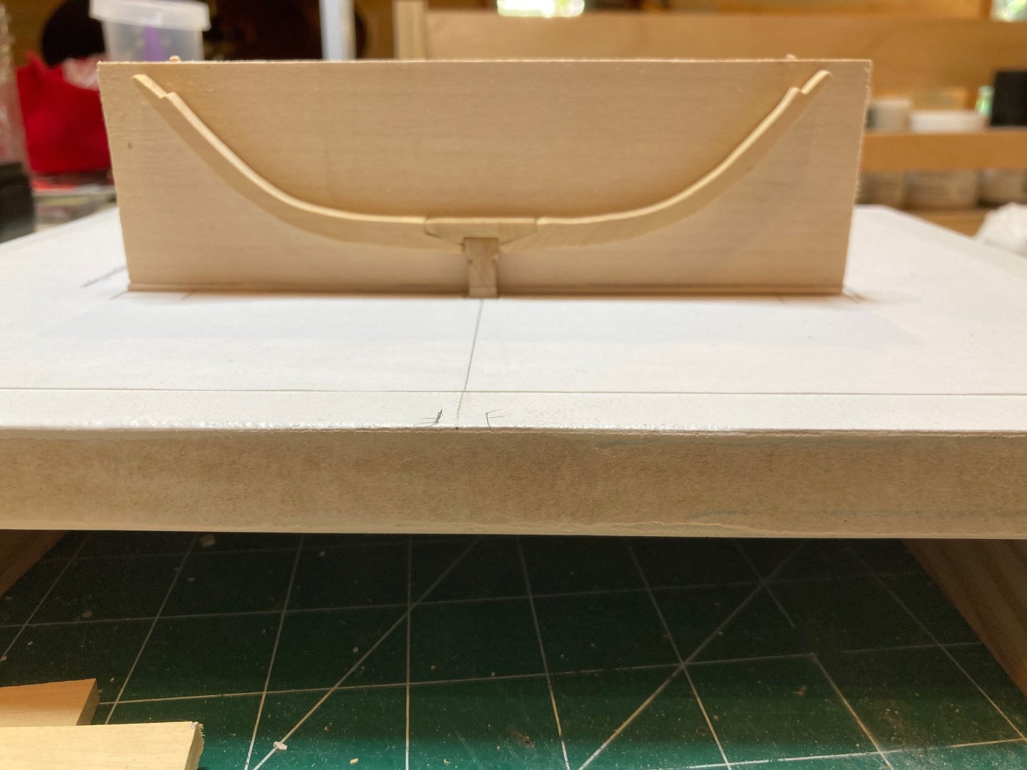
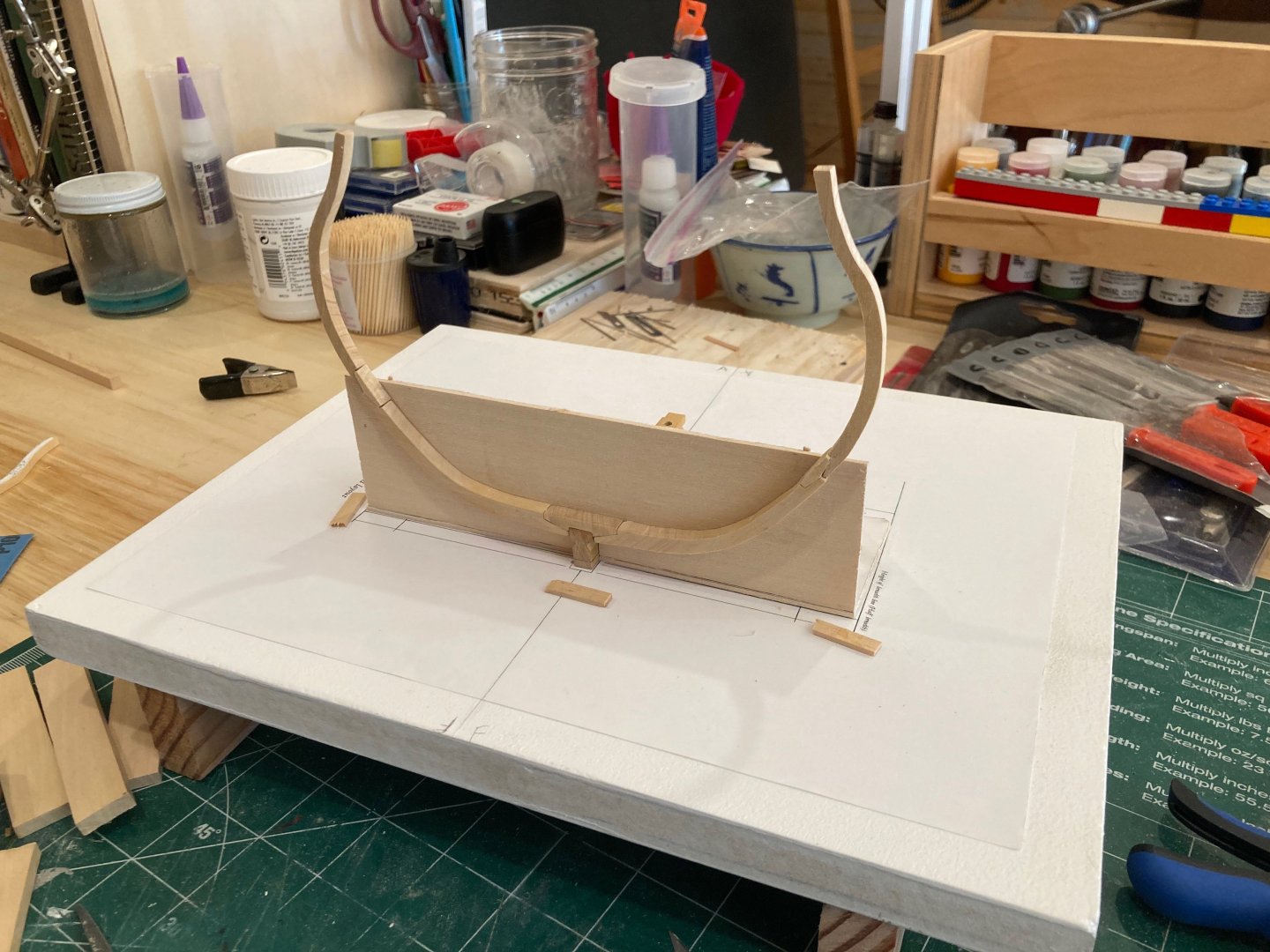
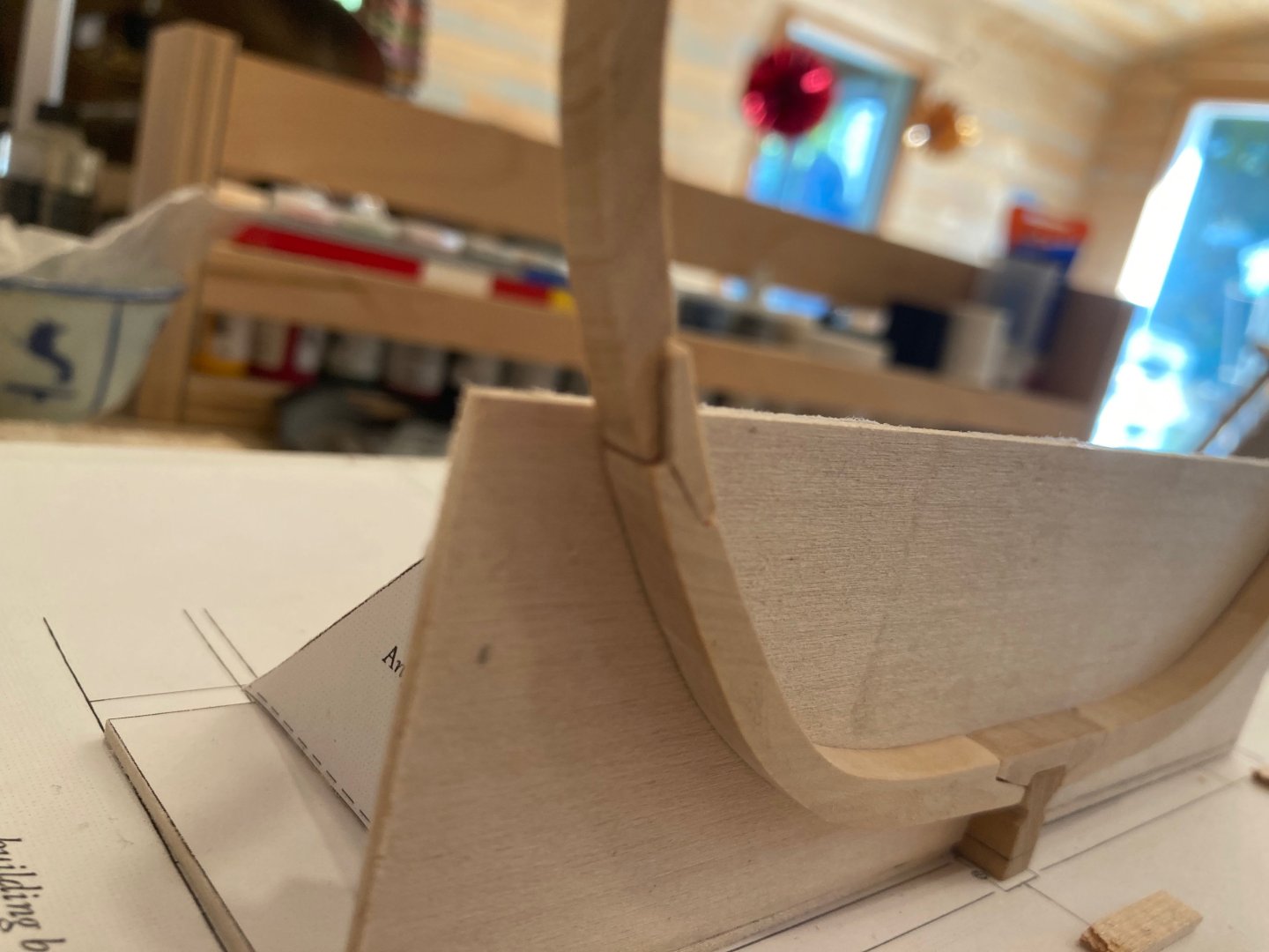
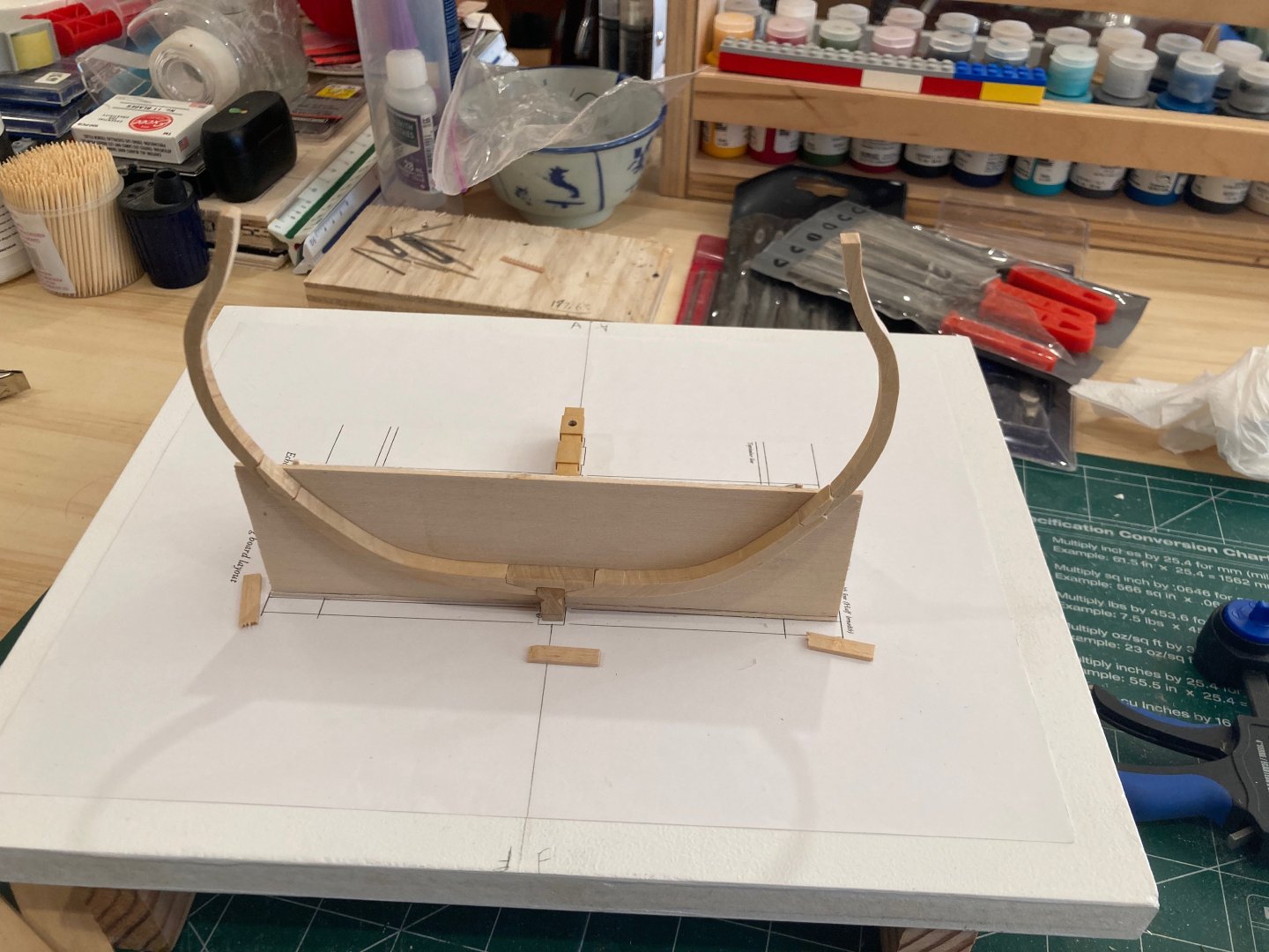
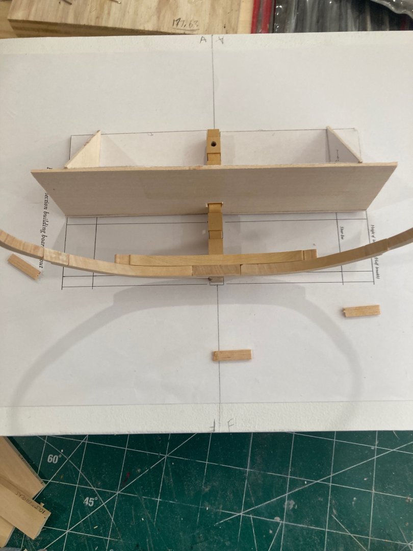
A final update - deadflat 1 has now also been raised, after notching it out on the aft face for the sweep port sills. Here are a couple of shots to round out the set....moving on to frame set 1 next....think I will continue to do these in pairs as long as that continues to make sense.... hamilton

-
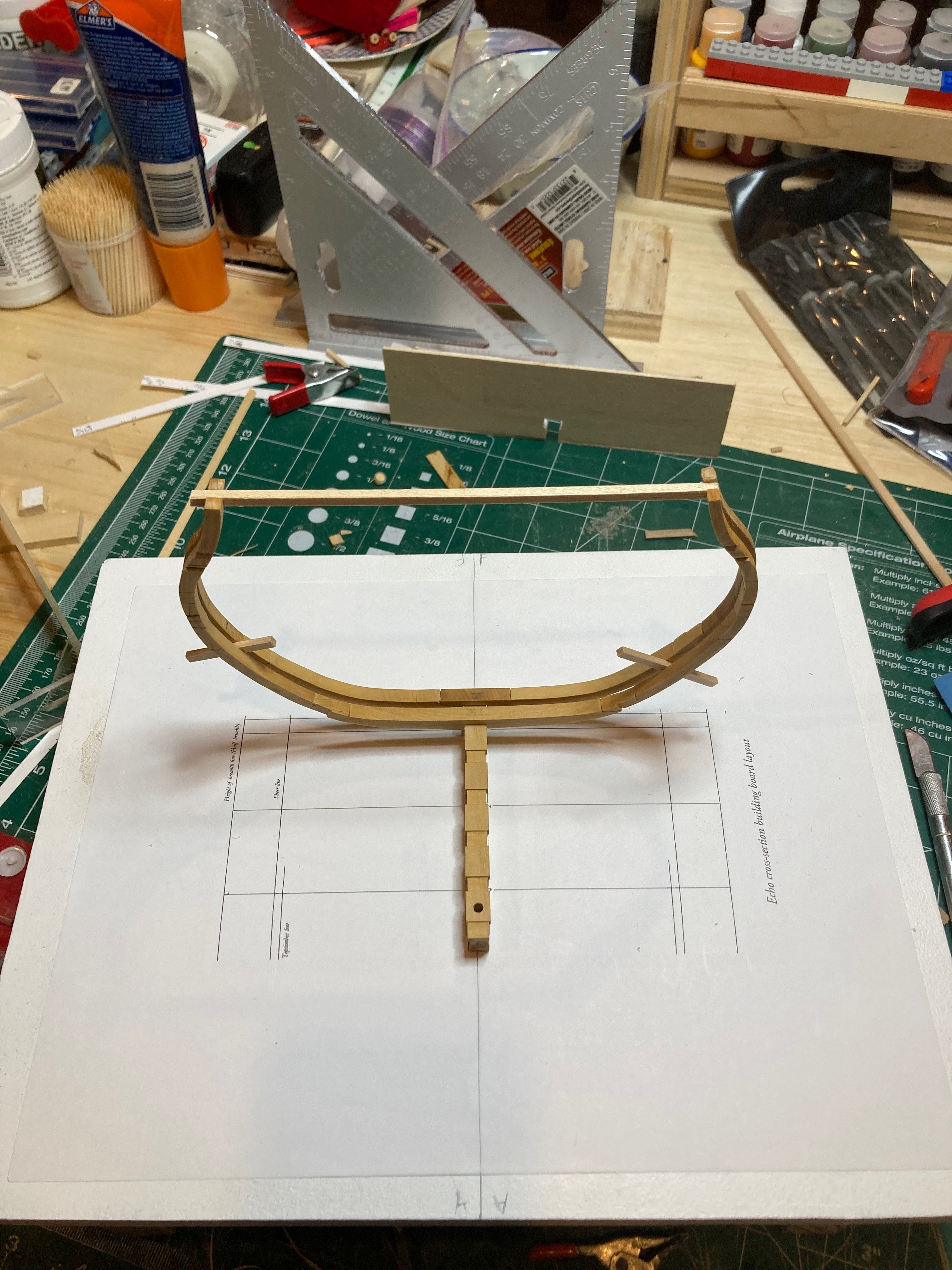
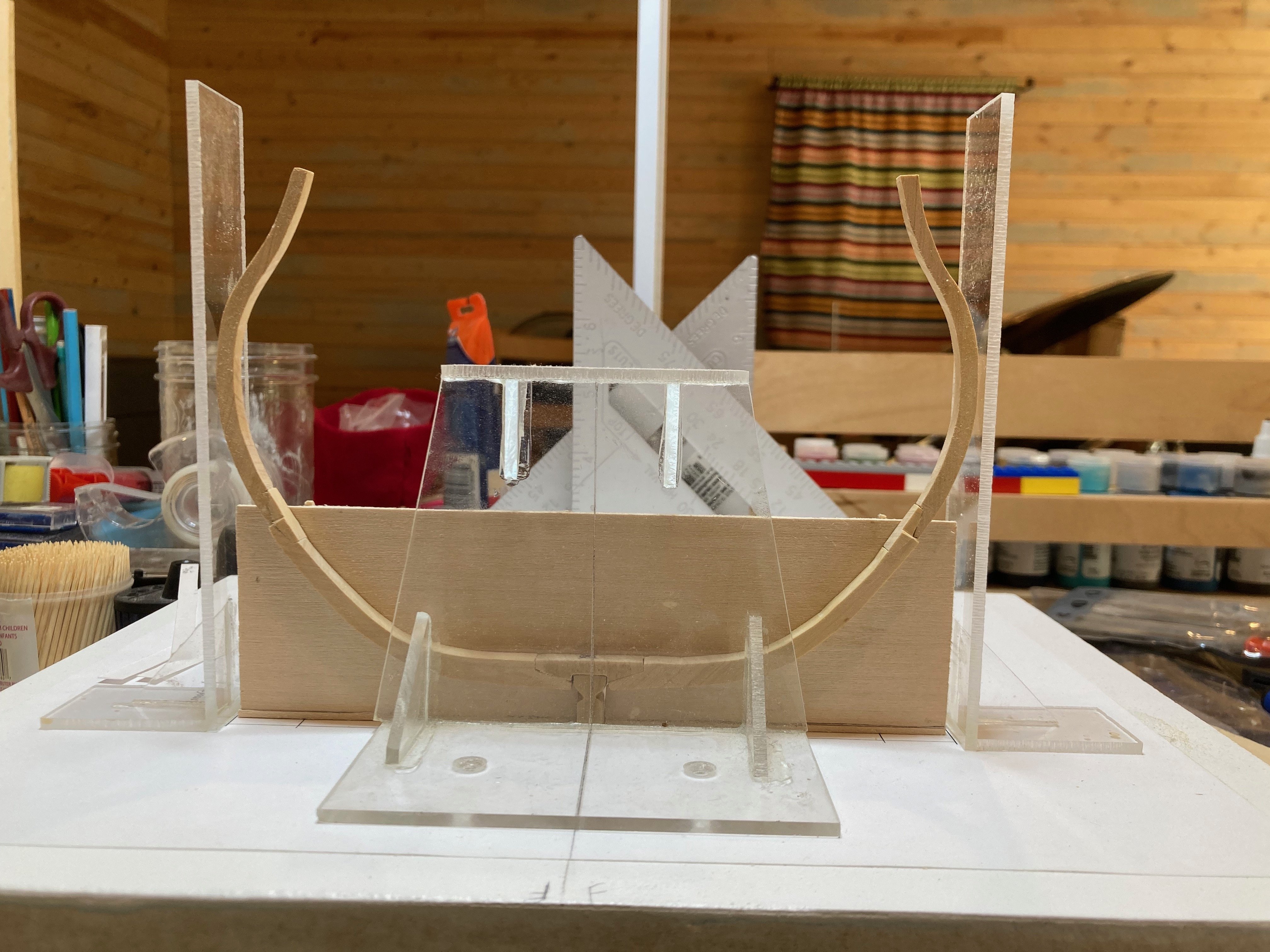
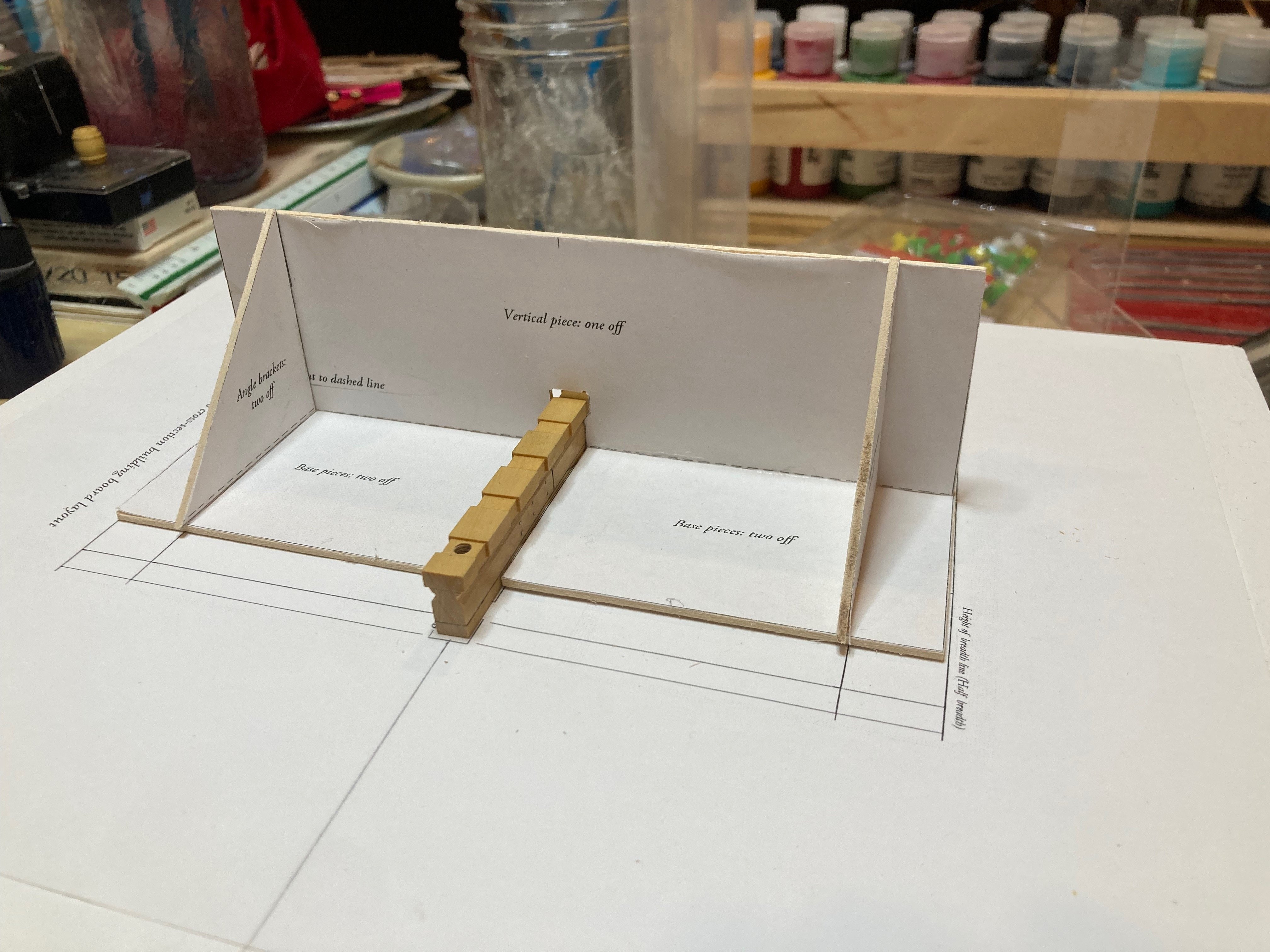
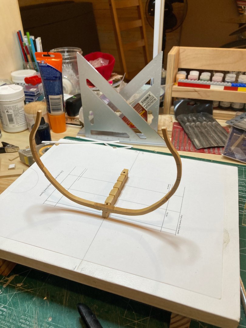
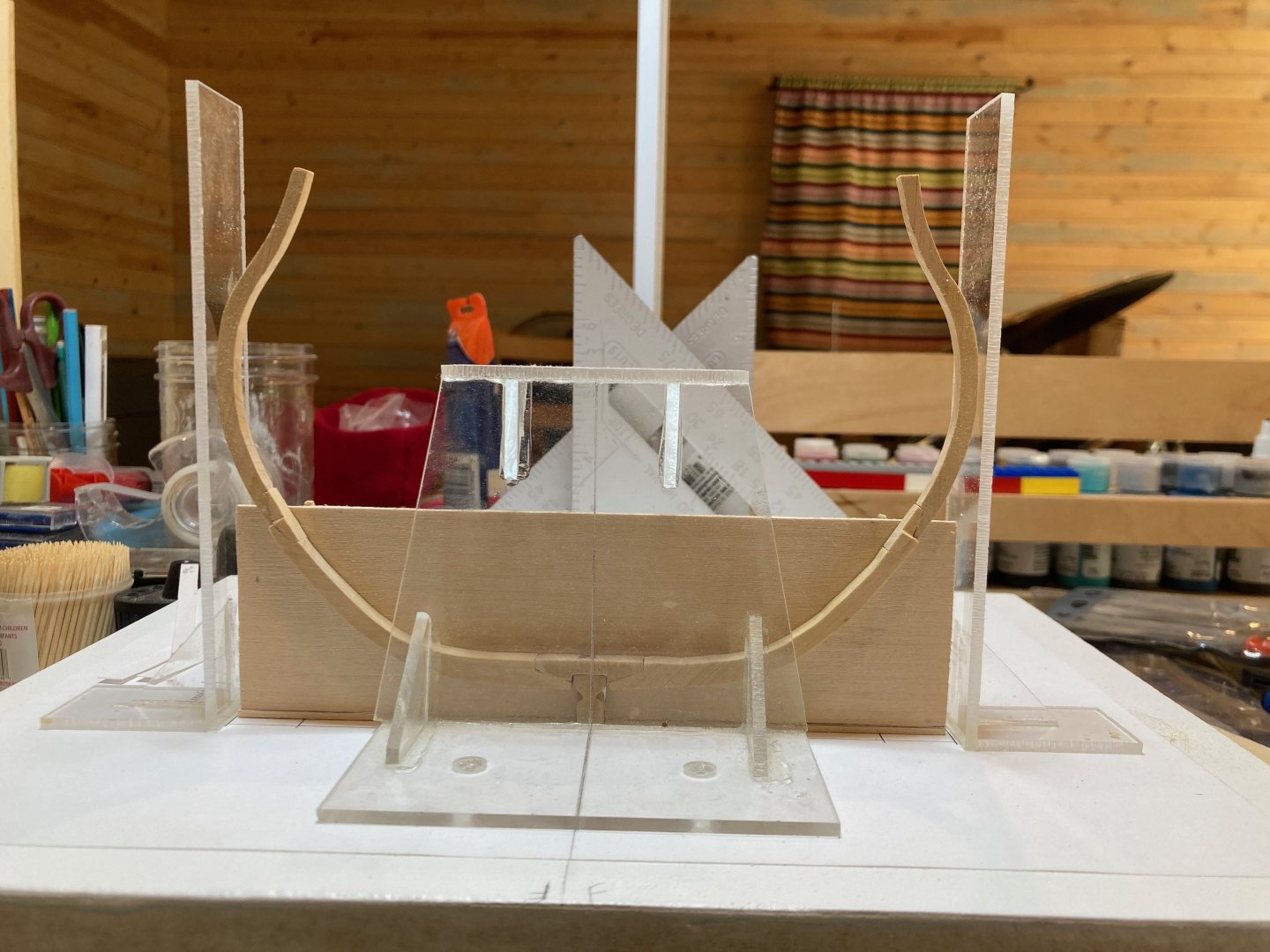
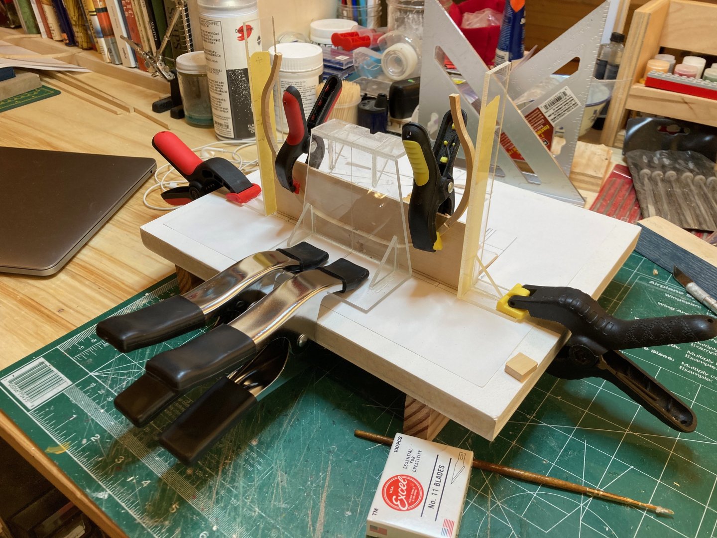
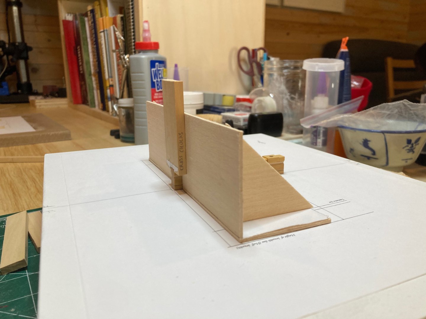
So I may have been pre-emptive, but I decided to raise the deadflat frame on the keel today. Doing so took quite a bit of finessing and was definitely aided by the deadflat 1 frame when it came to final positioning. The whole endeavour was slowed by the fact that I broke not one but both of the frames while adding the trunnels, and had to reset the futtocks and in one case re-make one of the chocks - which I did using the method suggested by Greg which worked way better for fit - still a bit of adjusting to do, but not as much as when I was just cutting them from the patterns on the frame drawings.... For mounting, the frame was merely glued to the keel assembly with PVA, which I will let cure for 24 hours before securing the seating with a length of brass rod - this will be invisible under the keelson, so I'm not going to treat it in any way, just use it for structural support. I lined up the frame along the reference lines on the lateral framing squares and clamped these in place. I then clamped the forward square along the centre line (I etched a centre line on the acrylic base and vertical support for certainty)and then clamped the frame to the aft framing square. Once this was done, I inserted some 2mm spacers (scrap basswood) between the two frames and used a length of 2mm basswood for a bracing piece at the top. This is only glued to the aft edge of the deadflat frame but clamped between the 2 frames to secure it. I was quite please not only with the seating of the frame, but with the alignment of the outside edges of these first two frames. I will be adding these horizontal braces to the tops of the frames as I go for structural support and to ensure symmetry and will saw the centre portions flush and sand down the remaining material flush with the frames when I fair the cross-section for planking. The bracing pieces you see further down the frame are not glued and will be removed once the glue is set and I'm ready to install deadflat 1, which I will do after completing frame 1 forward. Any comments, tips or feedback on this process are always appreciated. Thanks and bye for now hamilton


-
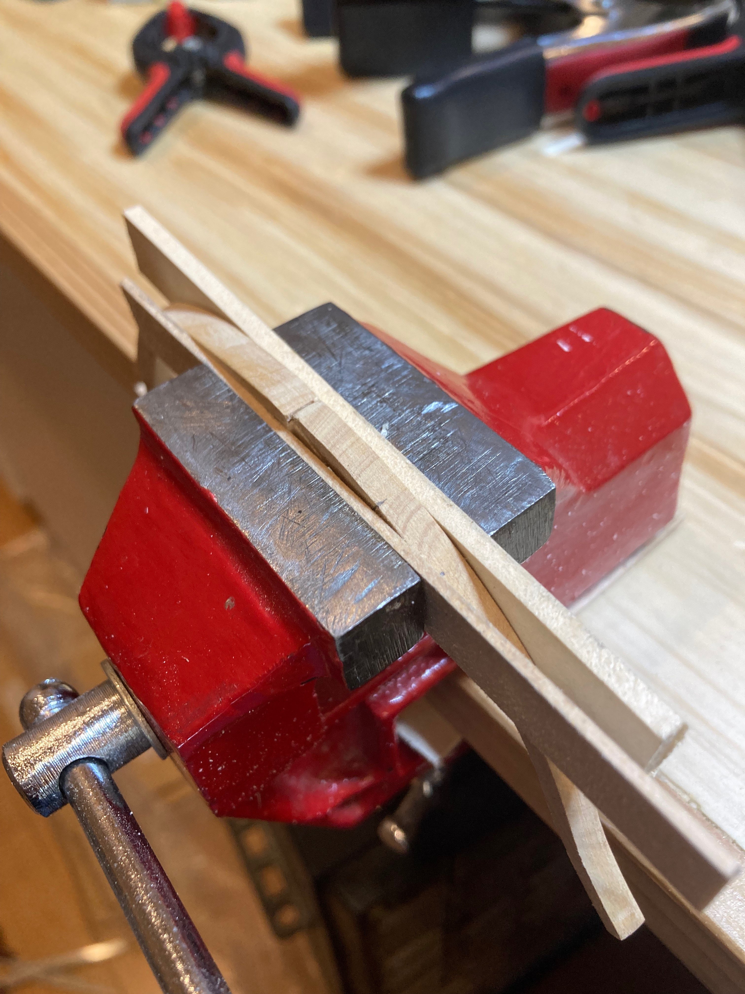
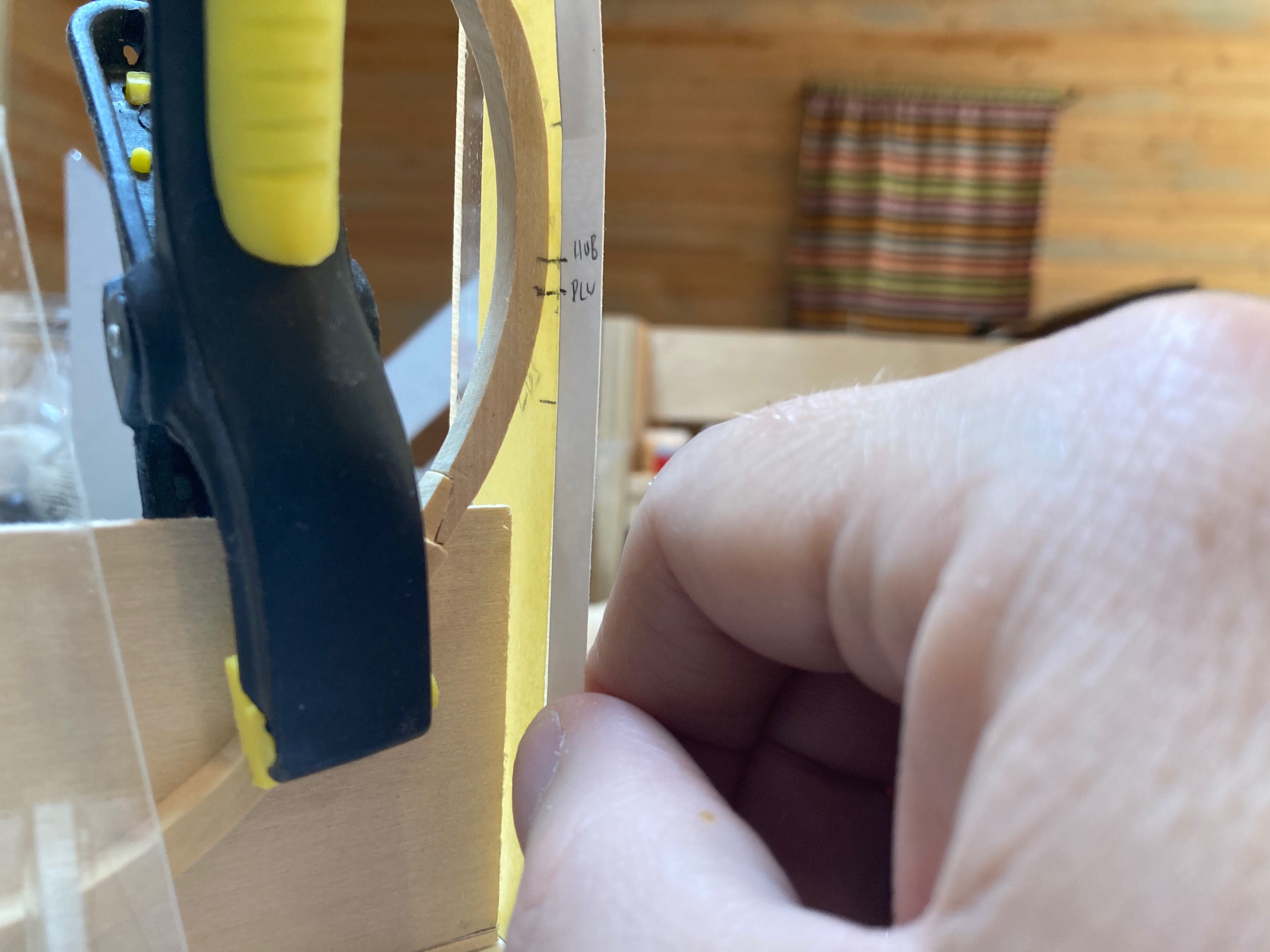
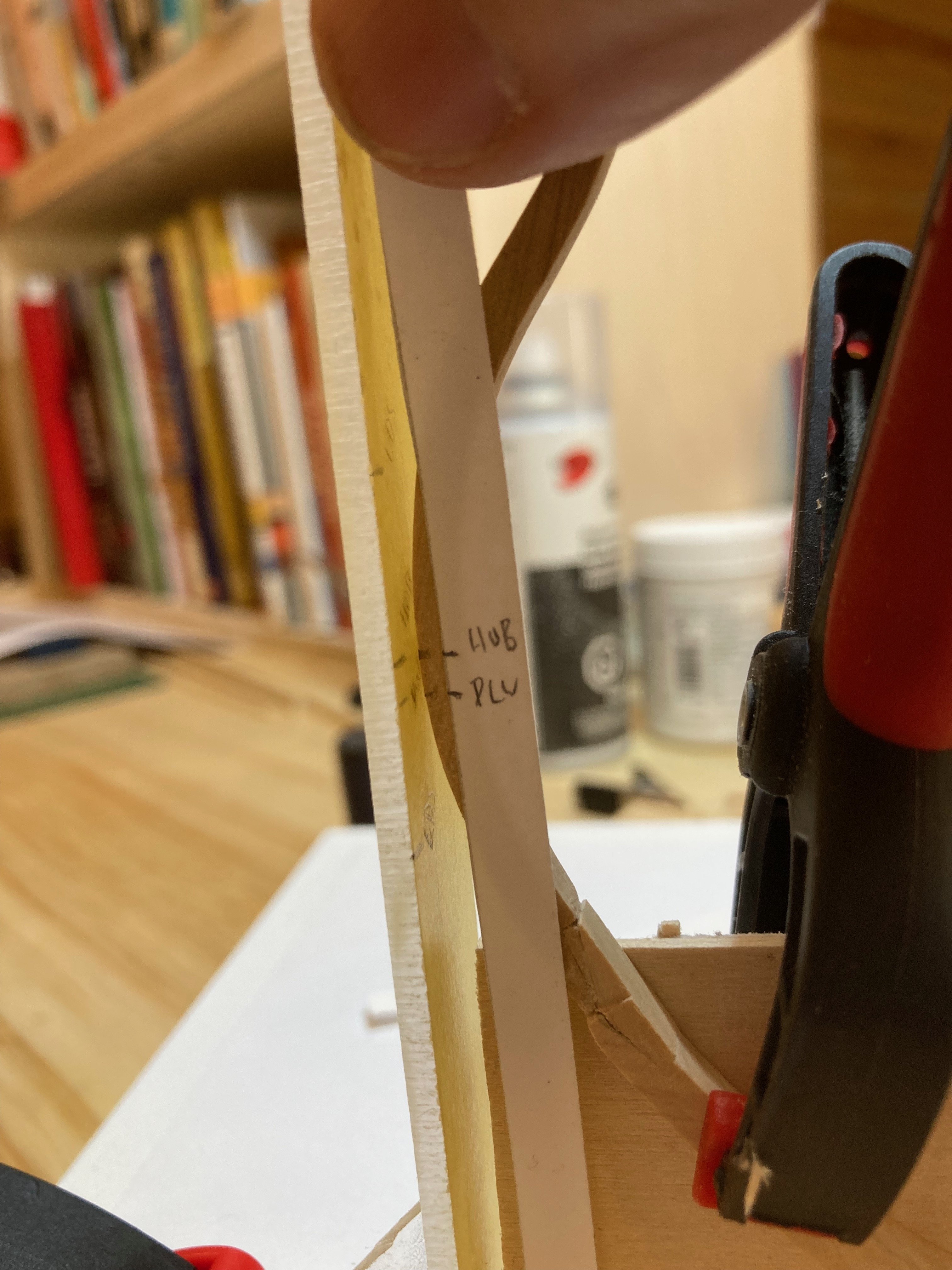
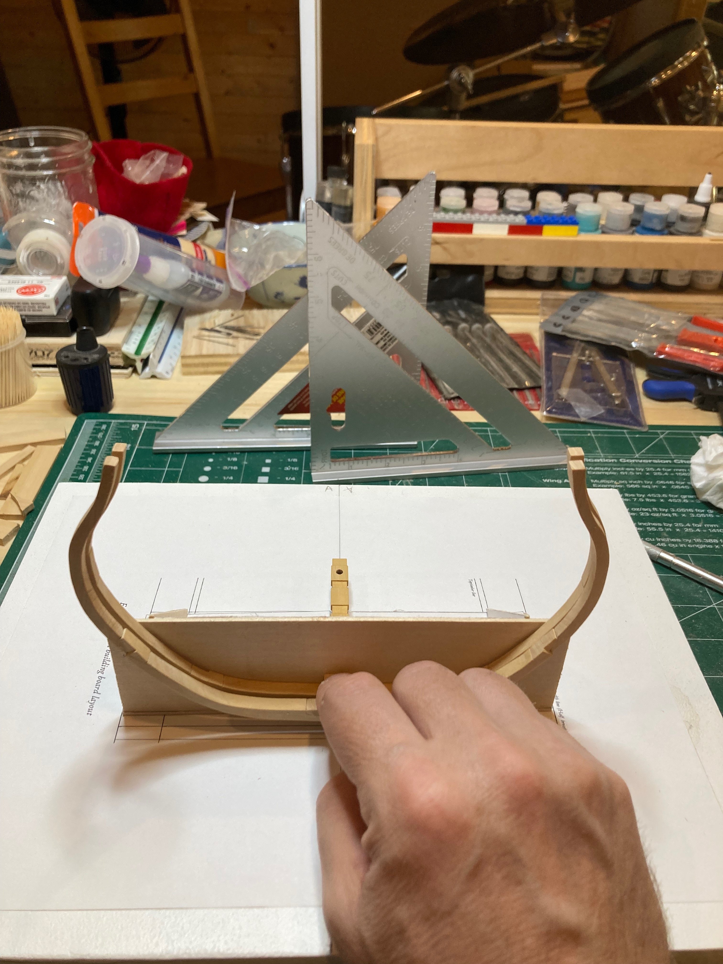
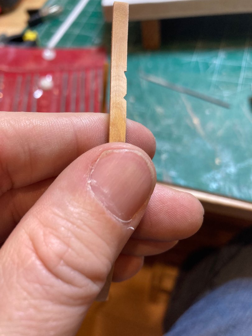
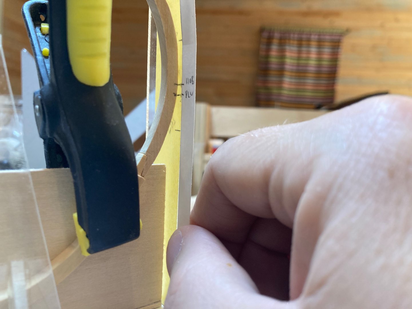
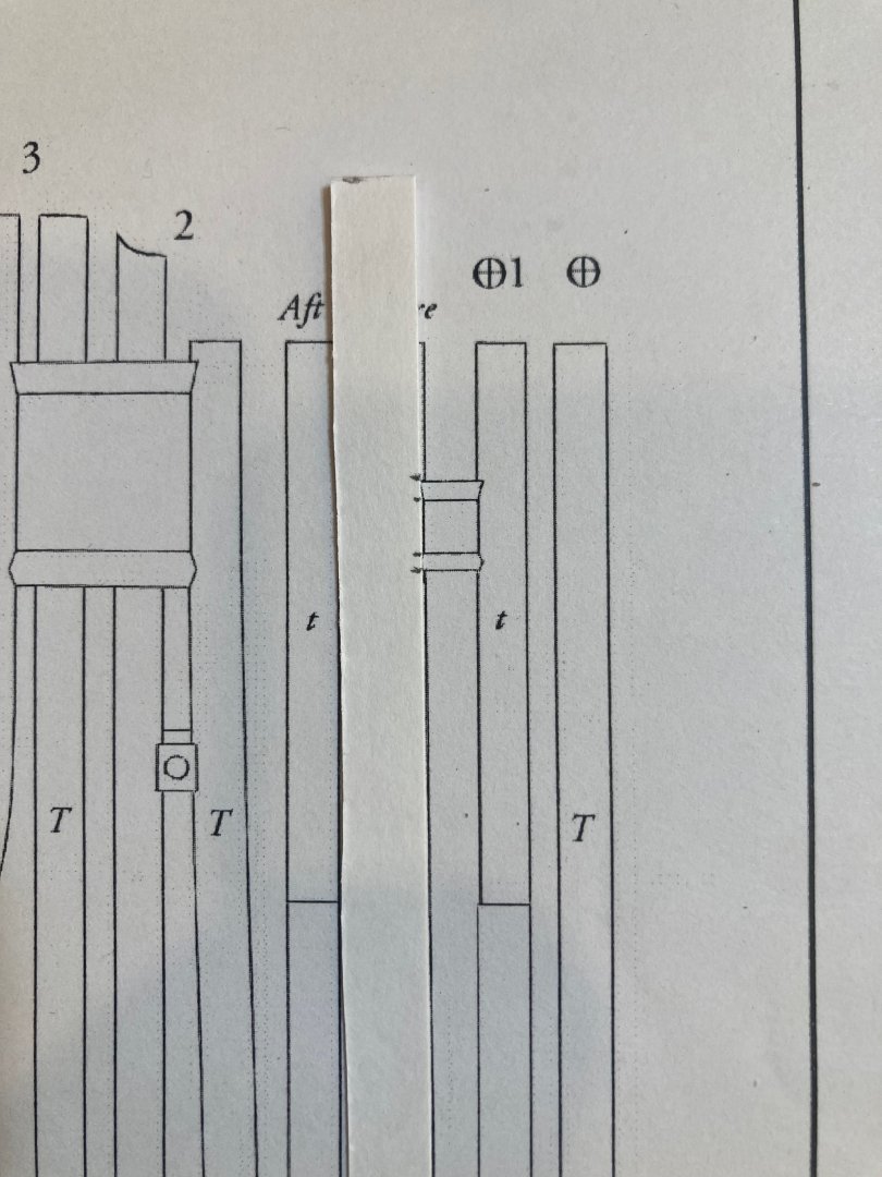
One last update for today. I used the markings on the tape strips attached to the right angle plates to mark out the lines on the front face of the deadflat frame. I then cut a tick strip and marked the lines on it from the profile drawing and checked against the marks on the frame. With a very small adjustment on the starboard side, the markings were nice, even & symmetrical. I then unclamped the frame and extended these marks across the face of the frame using a straight edge, and then extended the lines around the frame, so each line is marked out on all sides. I still need to add trunnels to the futtock joints, which should be interesting - the joints are such a tender spot that I'm not sure how to approach it in terms of supporting the frame so it doesn't break under even the controllable pressure of hand drilling....My current idea is to put the frame in my bench vice so the outside edge of the frame is just above the jaws and going for it from there....I have some cast-off futtocks that i made while practicing my scroll saw work so I might just glue up a couple of those just to see how it feels and how it goes....I guess I'm not in any rush! hamilton

-
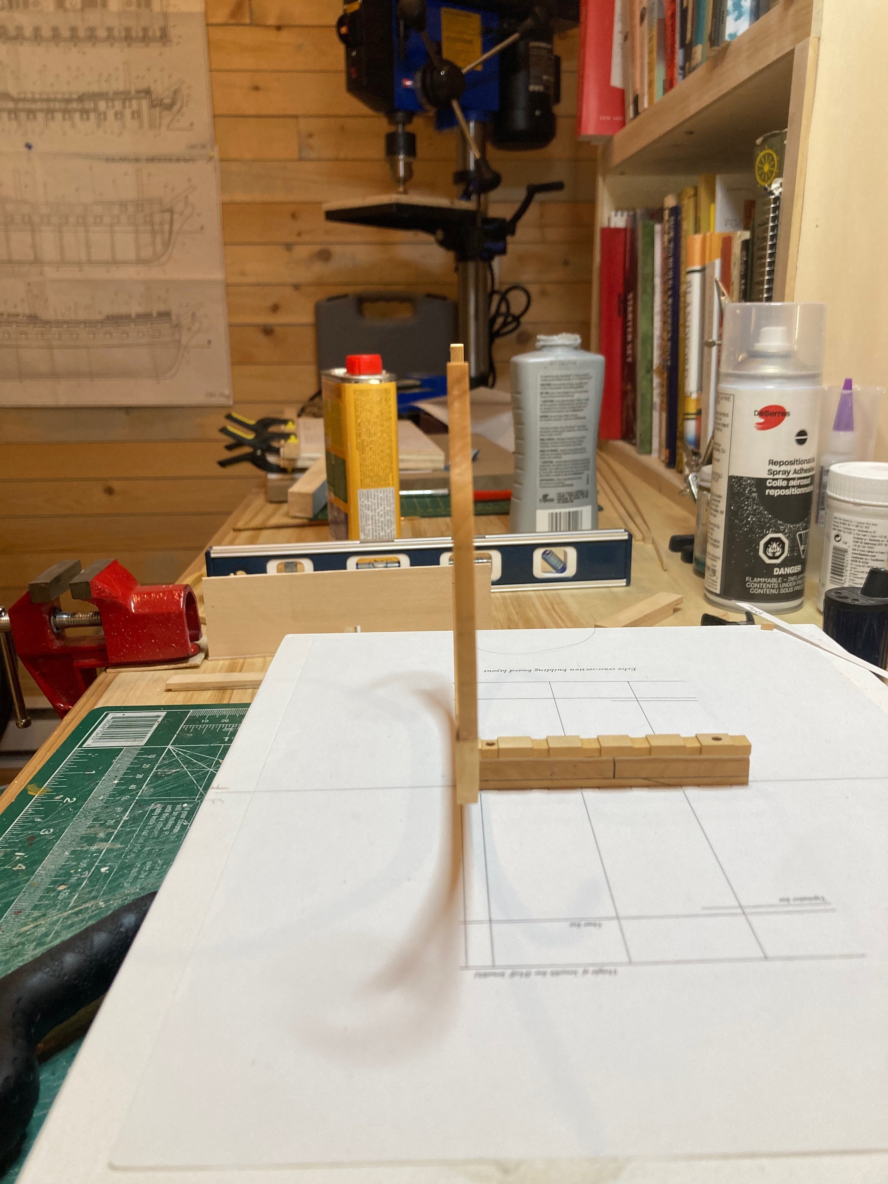
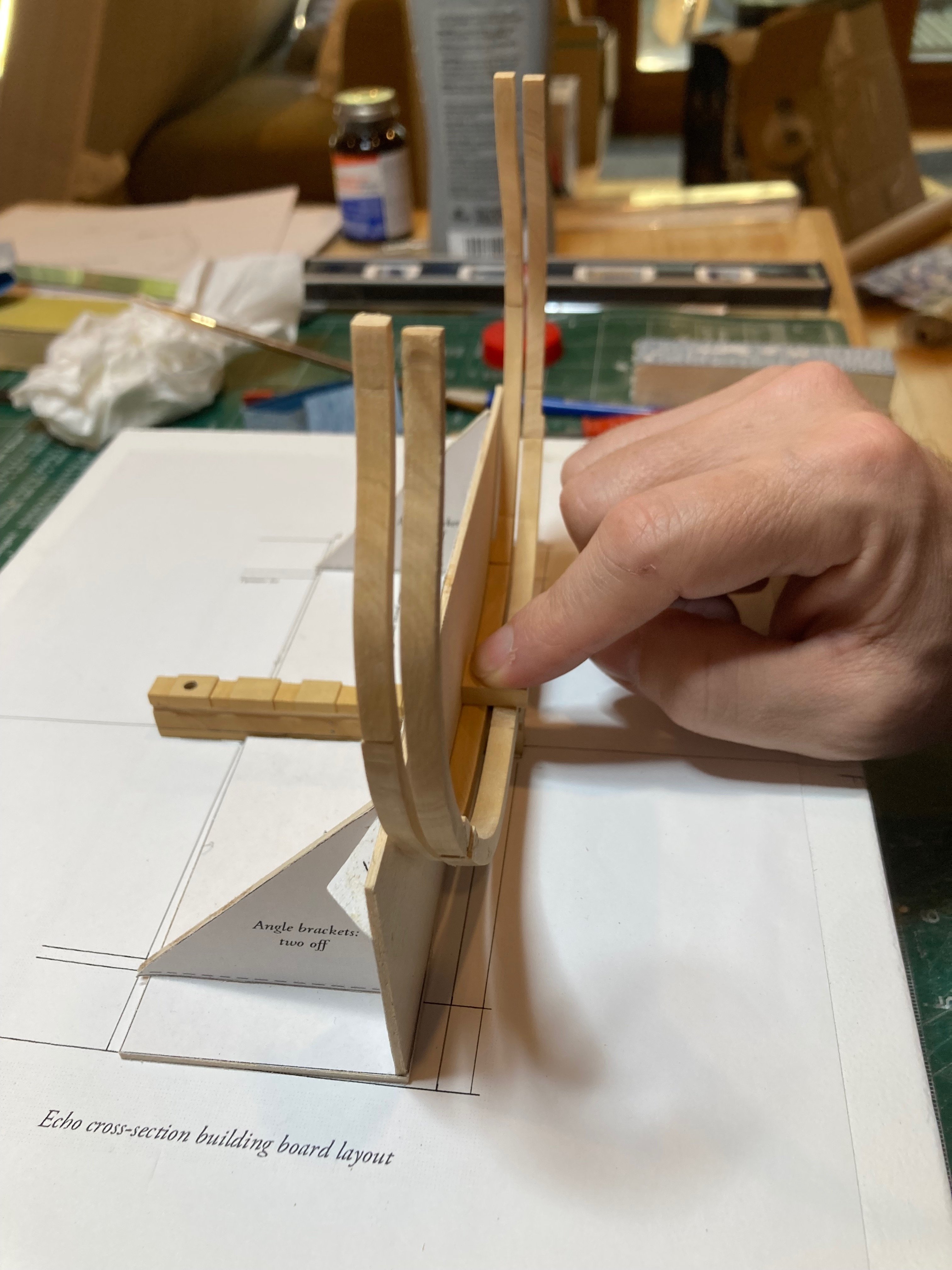
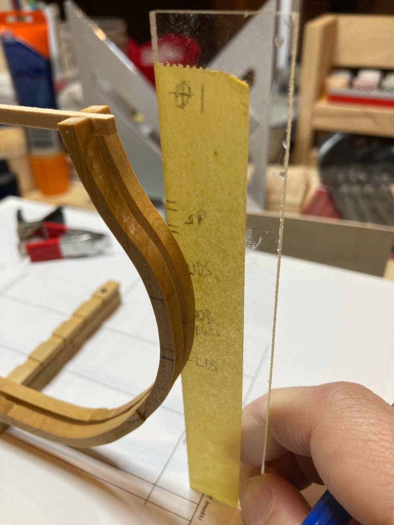
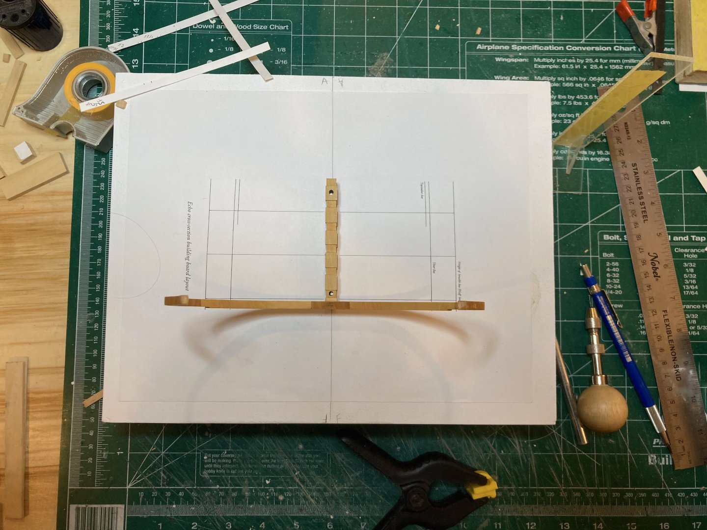
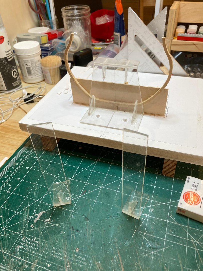
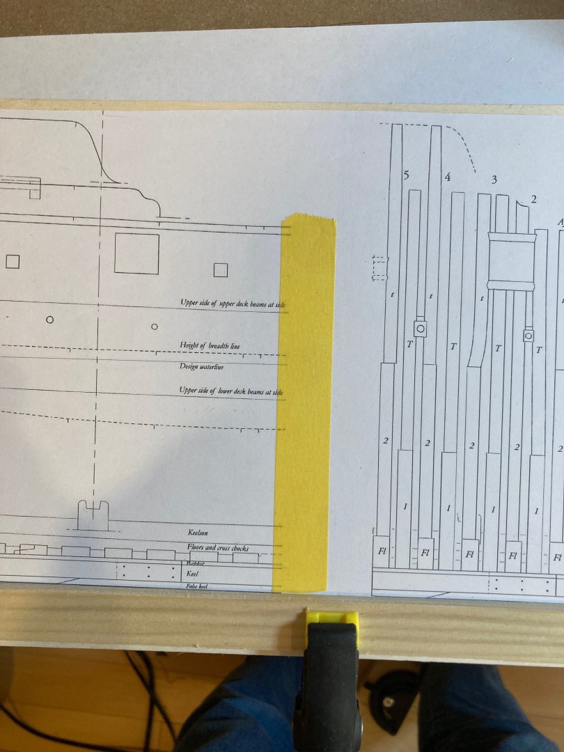
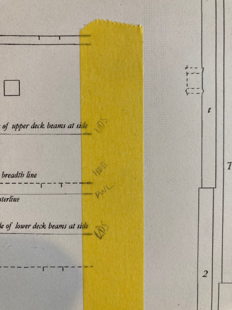
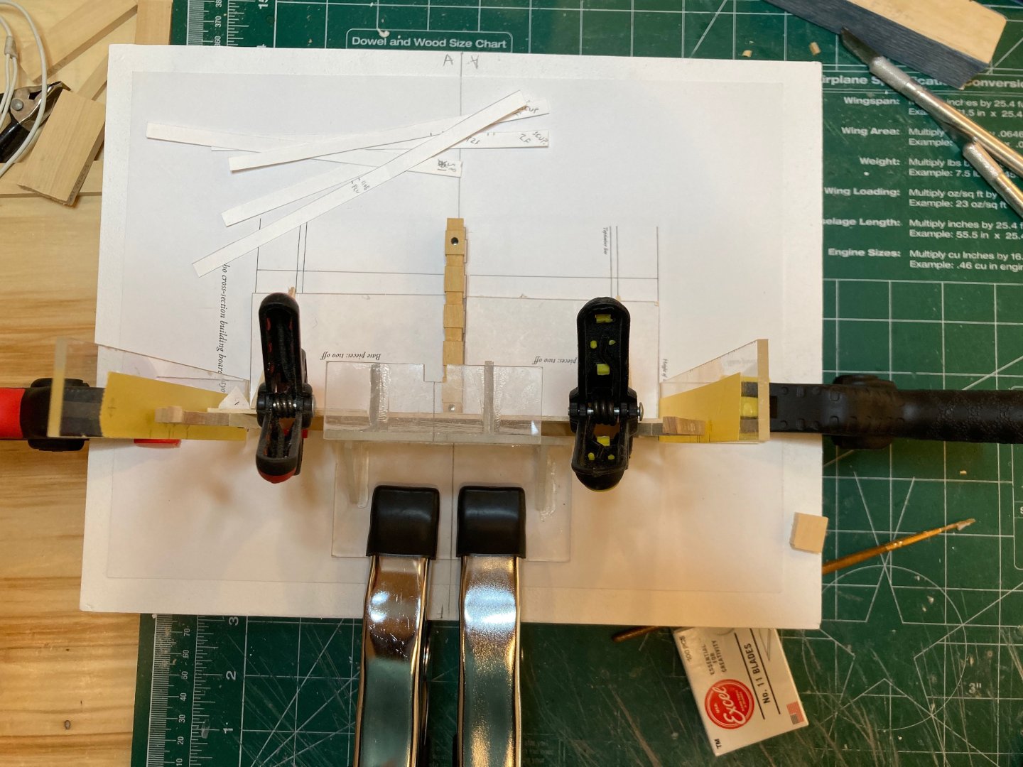
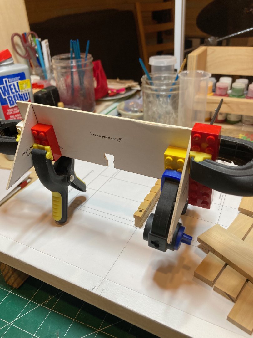
Thanks Alan - yes, this seemed like a much better approach than trying to line up tick strips. It'll be a little tricky as the model progresses, and I may need to modify the framing squares to allow me to continue using this method as I work aft - the framing square that I built from the Admiralty templates is too wide for me to be able to slide the acrylic squares in back of the frame for transferring marks. I'll see if I can puzzle this out over the weekend as I try to get my first frame raised. One thing I will definitely need to do is mark out the station lines as verticals on both the disposition of frame and profile drawings, so I'm sure I'm correctly laying the tape strips. This wasn't necessary for the deadflat frame as there is a little reference for it on the drawing itself, but it will be much better to mark them all out as verticals to ensure the reference lines are correct. In the meantime, I spent a bit of time last night testing the method and seeing if I could set up the deadflat frame with accuracy. Using the vertical measurement jig and some 1/2" masking tape (turned out I didn't have any more 1/4" stuff, which I think would be better), I took measures for the upper & lower deck beams at side, the height of breadth line and the design waterline. I then just peeled this tape off the jig and carefully lined it up with the edges of the square at the bottom and along one side - repeated for the port side square and that was that. The port and starboard squares were lined up with the height of breadth line on the drawing fixed to the building board and then clamped in place. In the photos below, I've set the frame up and clamped the fore and aft framing squares and the lateral squares. I found it useful then to take a tick strip with the lines marked out and used this to test the port & starboard symmetry of the frame and make minor adjustments to its positioning before final clamping. What you see in the final shots below is the frame set up on the building board ready to be marked out for the various lines noted above. The deadflat 1 frame needs also to be marked out for the sweep port notches on its aft face. In fact there are, I think, only 4 frames total that don't need to be notched out for sweep ports, gun ports and/or scuppers. A brief observation - the process of constructing frames has really re-oriented my focus and attention in modelling. The necessity to approach each component with care and thought for its relations is so much more on the surface of things than I've experience in my work on model kits, where I feel like I lag in conscientiousness here and there where the kit manufacturer has done the work for me....Even with my scratch Bluenose there were a couple of "auto-pilot" moments where I was leaning much more on the documentation supplied by MS for their kit, and where I felt I could fudge things without any overall bad effect. Here, there's no fudging things! It has to be right or it's not going to work - it's a lot of pressure, but it feels like there's a lot of learning happening too, which is fun. Here are some photos - I hope to have the first frame raised by the end of the weekend - I just need to mark it out, trunnel the joints, work on the keel notch to ease the fit, and it'll be ready to go......deep breath.... hamilton


-
A small update - not much time this past week for modelling, unfortunately, but I have a short break from work over the weekend, so hopefully I'll be able to make some progress. Today, I spent a very short time putting together a simple jig for taking vertical measurements - it's just the profile drawing adhered to a piece of 3/4" plywood with a batten clamped along the line marking the bottom of the keel. I made some tick strips out of card, but I think I will take a different approach to transferring these marks - I have a number of right angle plates that I made from 1/8" acrylic some time ago and the taller of these can be used to transfer vertical measures to the model - instead of using tick strips on the drawing, I will use 1/4" masking tape which can then be fixed to the right angle plate itself - perhaps a more stable way of transferring the measures, but we'll see how it goes - I'm going to try to mark and file out the notches for the sweep port sills and lintels this weekend using this method. hamilton

-
Beginner looking for advice on first kit
hamilton replied to O-Nurse's topic in New member Introductions
Yes, Ross, but the amortization case is relative to cash flow, so the logic might not work for everyone - if I don't have $500 to drop on a model kit, then it doesn't matter how long it takes me to build it. As you might be able to tell from my signature, I clearly have a hard time following what I call "logic" myself! In any case, not knowing exactly the financial situation of other modellers, I hesitate to make recommendations based on what I might be able to afford. Personally, I applaud the efforts of designers like Chuck and CAF who offer larger, more expensive builds in chapter form - this immediately makes the economic calculus of this hobby a little easier to work for more potential modellers and is a very welcome business innovation in the current economic climate. Your Diana looks great, by the way! hamilton -
Beginner looking for advice on first kit
hamilton replied to O-Nurse's topic in New member Introductions
Lots of good advice here - I'll chime in with an extension on Frank's advice above - this is not a cheap hobby and tools are as important as kits - given what you say about yourself above, I imagine you've got some decent tools - but modelling tools can get quite specialised on the tool front - your full sized table saw is a little too much for the kinds of jobs a miniature table saw gets put to in ship modelling, for example, and it's doubtful that you'll need to invest in a micro-lathe to turn your own canons or rail stanchions until you get right into the weeds of the craft. I built my first kit with little more than a dremel tool, some #10 and #11 exacto blades, a set of small stainless steel tweezers, a pin vice with a set of micro drill bits, a little saw and a ball peen hammer - all purchased on the cheap to begin with and then replaced with better quality stuff as I discovered that this is something I like doing and want to keep doing and learning about. With some of the beginner kits from Model Shipways (which I would recommend as first attempt) that's all you need and since the beginner kits are usually quite affordable you're not breaking the bank just to see if you're into the hobby or not. It's tempting to go for a fully rigged ship of the line or a big 19th century clipper, since they look so cool, especially in the hands of some the pros on here. But they will very rapidly overwhelm if you don't first develop a general feel for the craft and work your way up - starting small and joining this forum are two decisions you won't regret! hamilton -
Thanks OC Christian - I'm not sure...but I suppose I'll find out...and I'll try to be conscious of this as I go....thanks! hamilton
-
Thanks Greg for this clear explanation - your approach to the chocks makes a lot of sense - I have been using the drawings to make these to this point, so I'll try your technique. I've already got the mechanical 2mm lead holder and hard leads but maybe a new disc sander is in my future....Thanks again - this is very helpful! hamilton
-
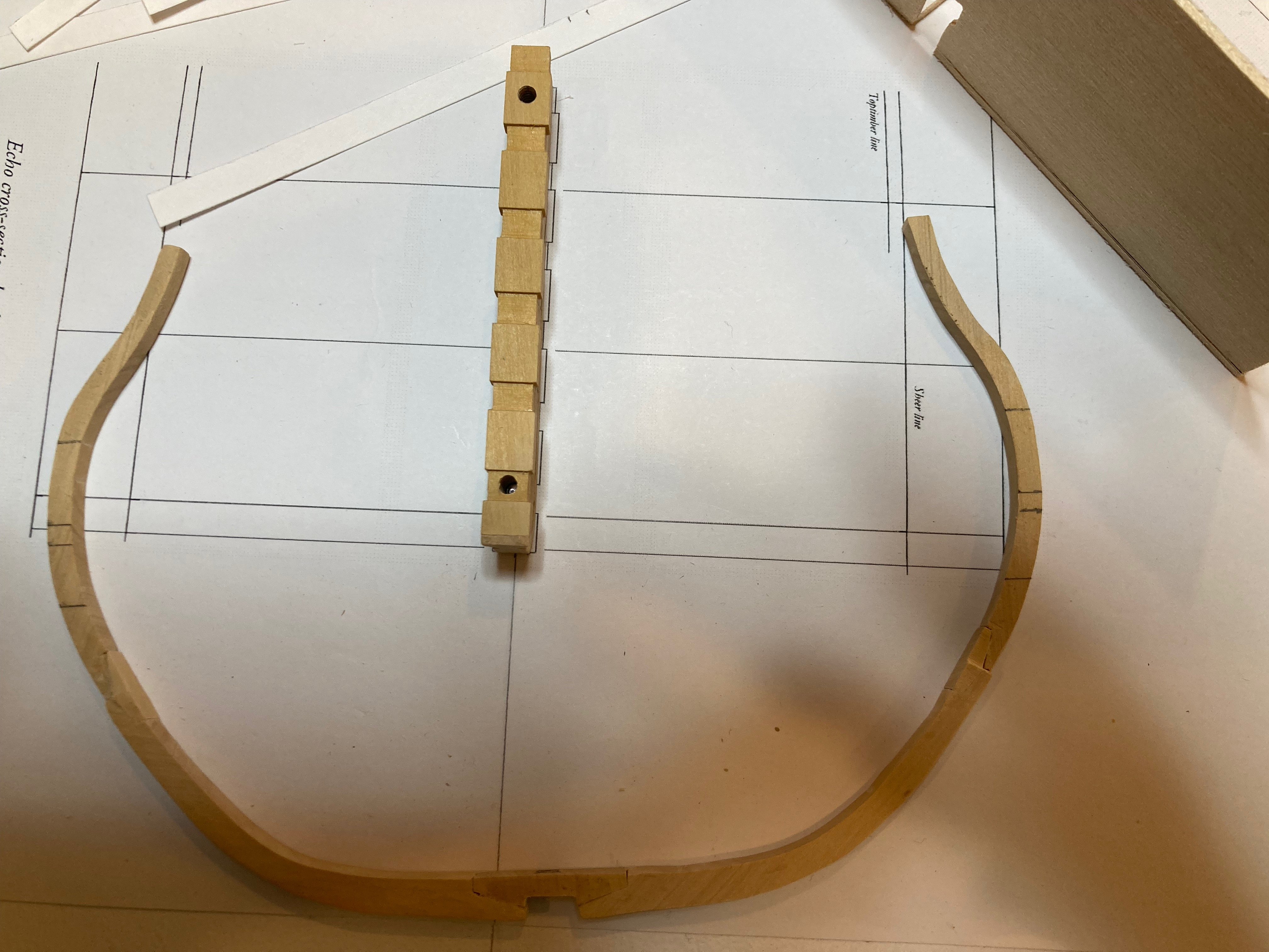
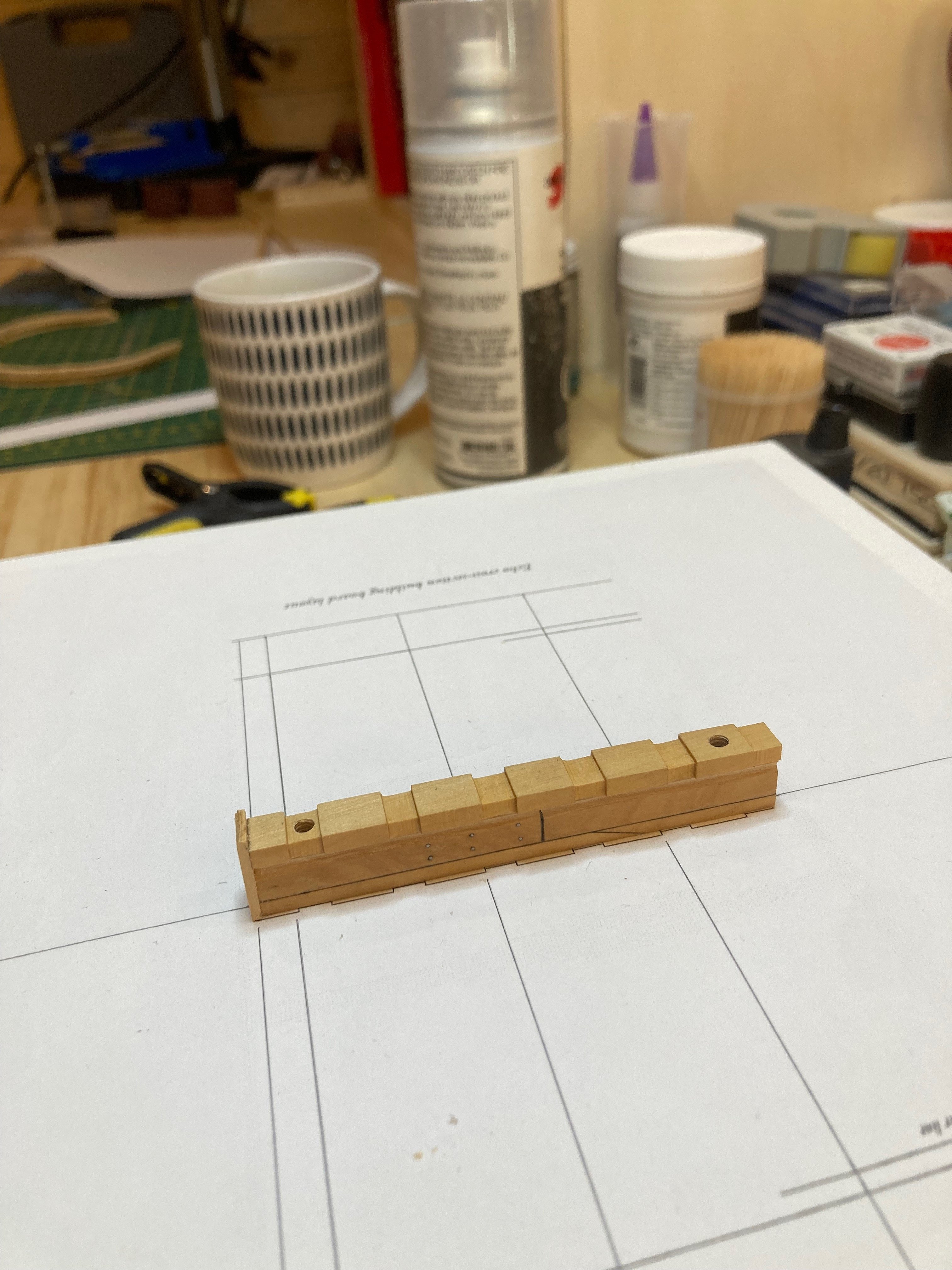
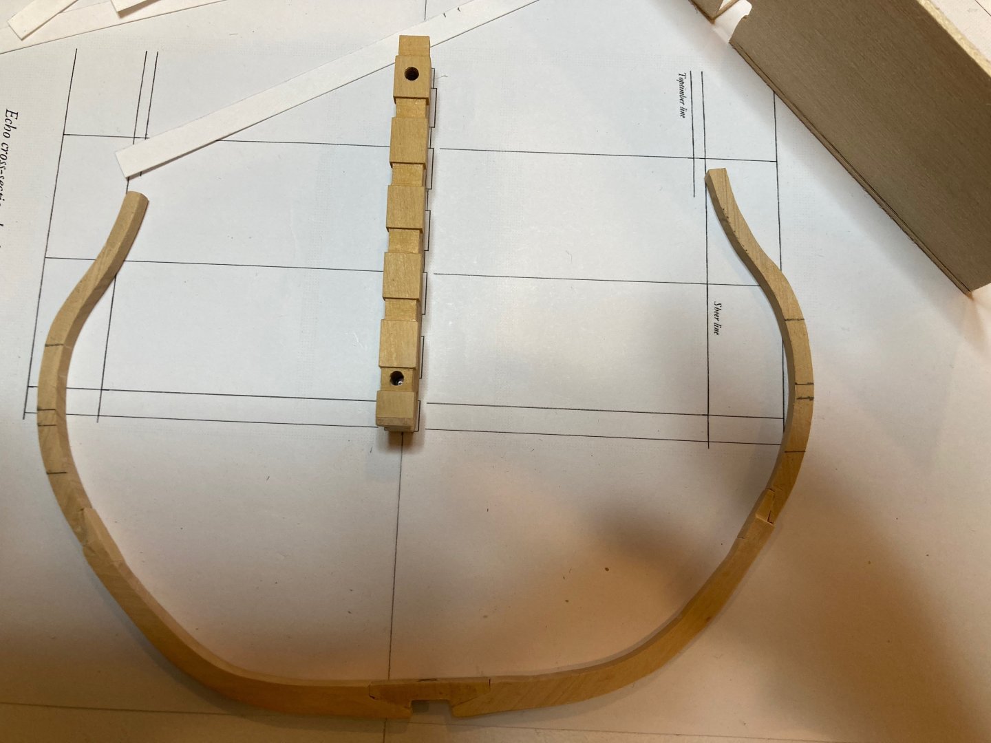
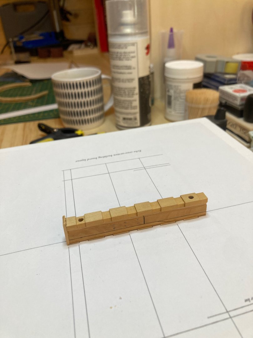
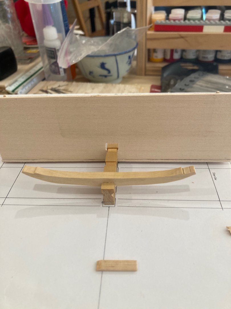
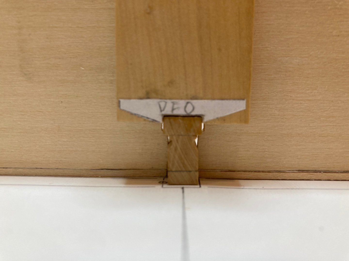
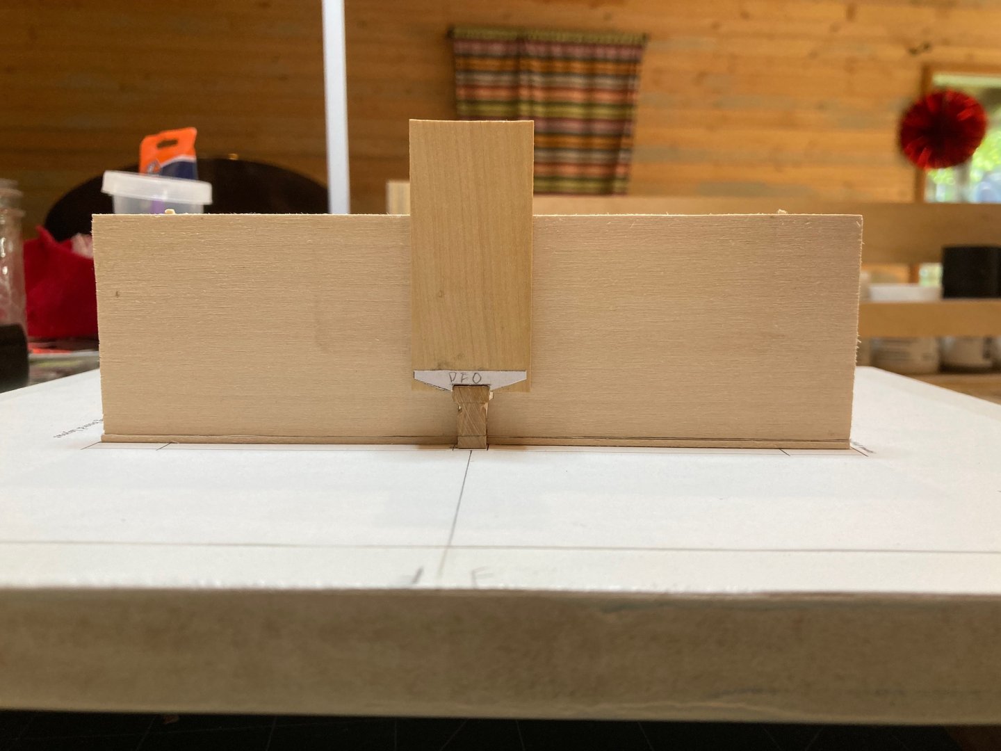
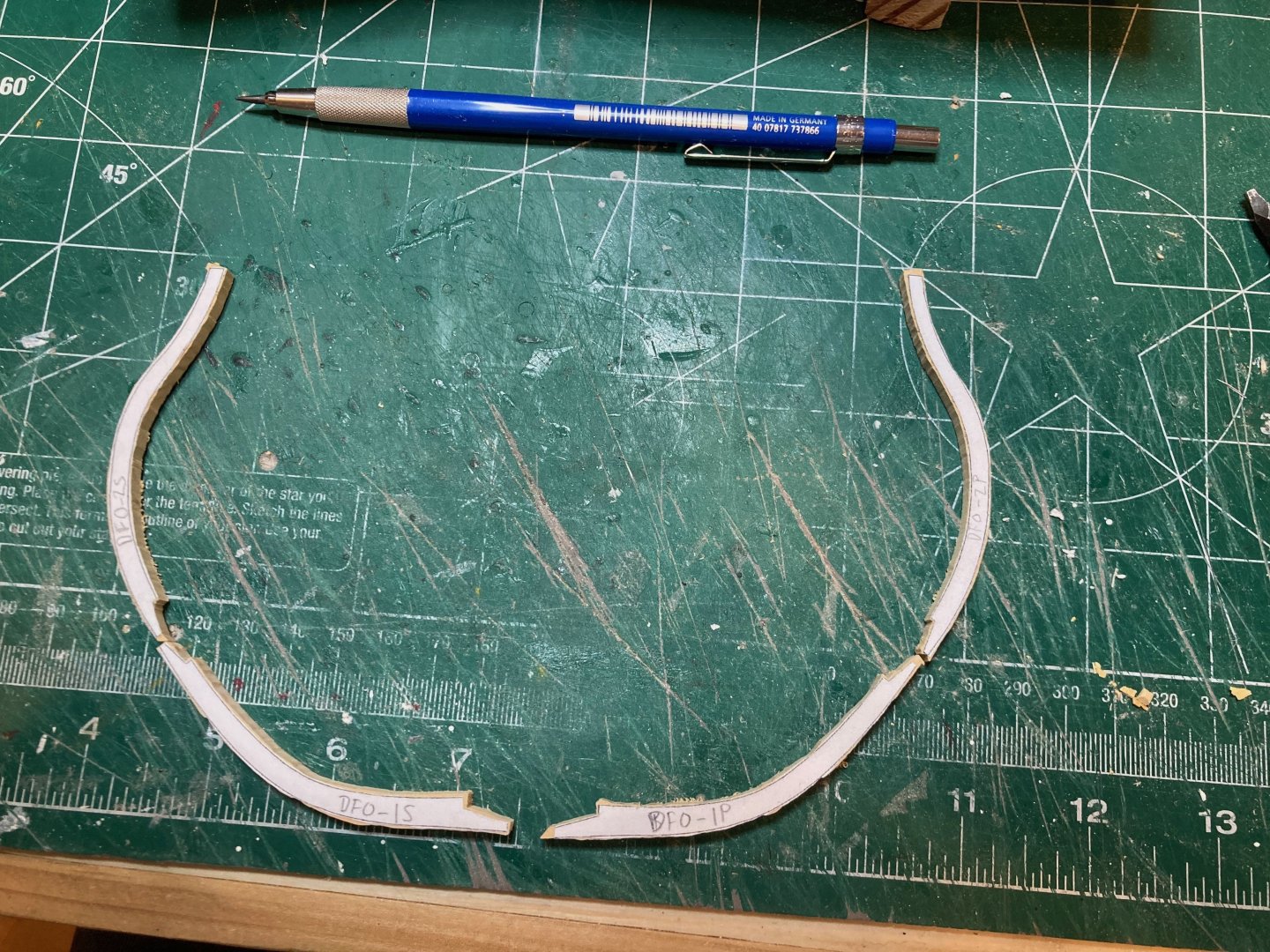
I've now constructed the first two frames - deadflat and deadflat 1. There is still a fair amount of cleaning up and refining to do, but for now I'm pretty happy with the results. The joints on deadflat 1 between the futtocks was pretty weak and I had to redo the chock to try to refine them, which was successful enough for the moment, but I really need to get a decent technique down for these joints so they are more secure....apart from "practice makes perfect" are there other things I should be doing to ensure better joints at the chocks? In any case, there is still work to be done on both frames - I need to refine their profiles along the molded dimension, thin them on the molded dimension towards the toptimbers, file out notches for the sweep port sills and lintels on the aft face of deadflat 1 and add trunnels at the joints. Given the need to align the notches for the sweep ports, I will wait to raise deadflat 1 until frame 1-forward is complete, so I can mark these features out at the same time on both. I also fixed the issue with the keel assembly noted above - I sliced off a short length of 1/16" boxwood from a thicker strip, fixed this to the end of the keel assembly and then shaped it with sanding blocks and files. Unfortunately I only have shots of the un-shaped extension attached to the assembly and not the finished piece - I'll see if I can show it more clearly in a future post. In the meantime, here are some photos. Enjoy and bye for now hamilton


-
I live in Vancouver, so the humidity would argue for the wood expanding....if I were in Scottsdale, maybe it would get all the moisture sucked out of it....this leaves only one possibility - modeller error!! I think I will take a minute or two and just add a 1/16" piece to the front and shape it to suit - not sure I'll be able to blend it very well but as you say Greg it's in a relatively unobtrusive spot.....framing is far more fun than I thought it would be!! But I've got to get my joinery down...... hamilton
-
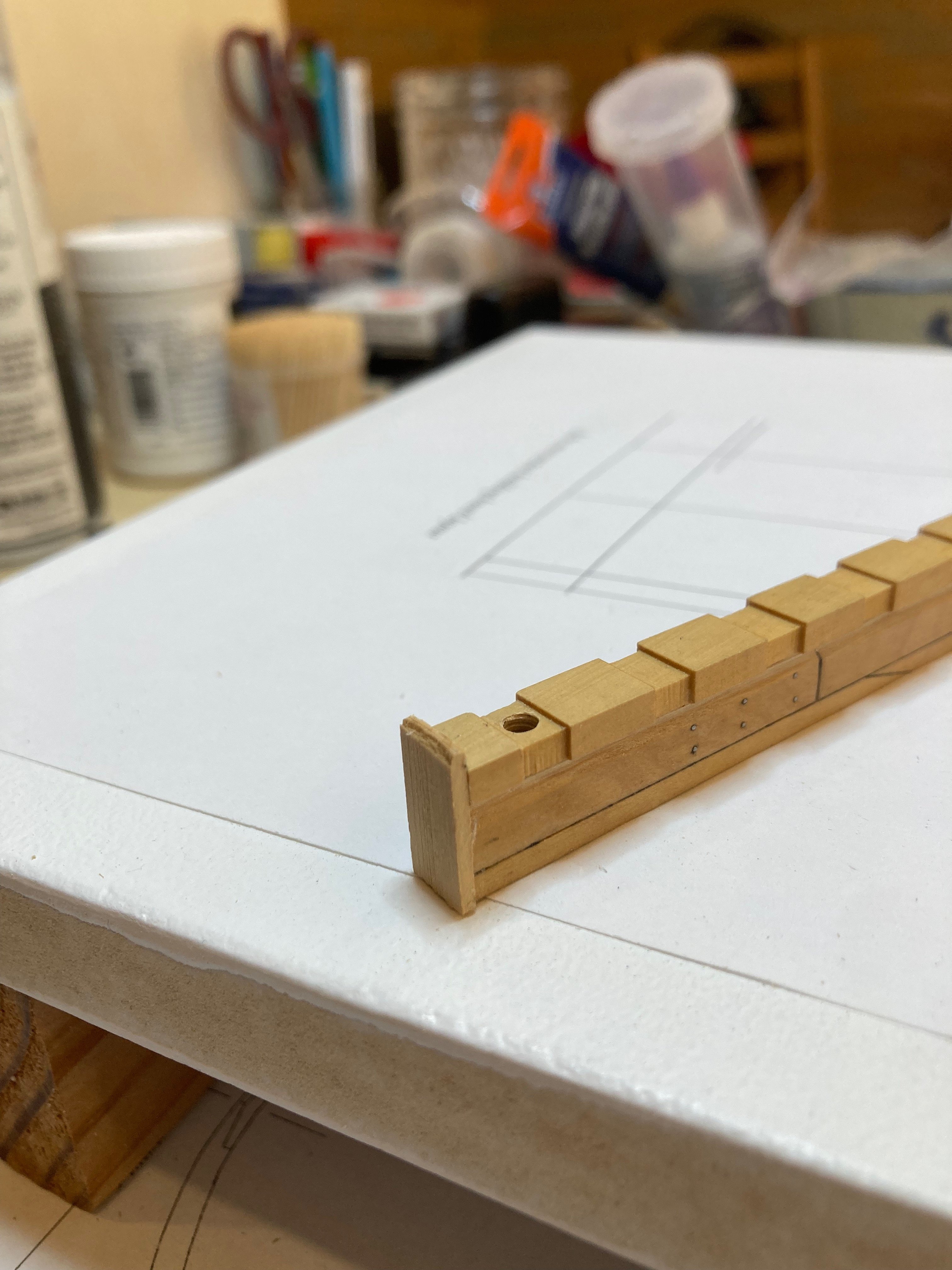
I'm just noticing something for the first time and kicking myself I didn't notice it before, since it is so obvious! You can see in the photos just posted that the keel assembly is short on the plan drawing - by maybe about 1/16"!! Half of me is tempted to simply attach a 1/16" thick strip of boxwood to this end and shape it to fit - though this will not look as good as it would if I just re-did the whole assembly......arghhh!! hamilton
-
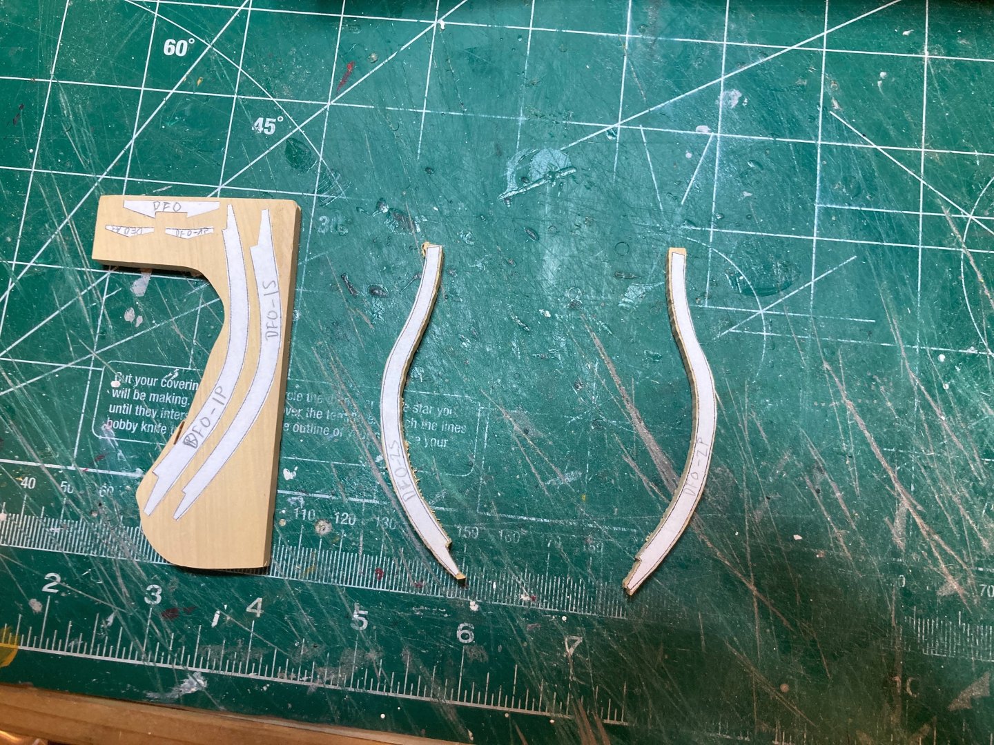
Continuing with the framing - I've now assembled, but not fully completed, the deadflat frame - it remains still to clean up the edges a little, trim down the portion of the chock that steps down from the first futtock to the toptimber, and add trunnels at the futtock joints. I will say that, though my joinery work leaves a lot to be desired (and indicates the need for more practice), I'm pretty pleased with the results. Of course, it's just one frame, so I have to be a bit reserved and wait to see how things shape up as keep going. I started working on the deadflat 1 frame today - making templates, cutting the components out on the scroll saw and doing some initial clean up of the parts. Once the glue has fully cured on the deadflat frame, I'll return to finish it up. Quick question for anyone who might know - is it best to wait to start raising the frames until all are constructed? I can't think of any advantage or disadvantage in raising them one at a time or all at once, but I wanted to ask just in case I might be missing something..... hamilton

-
Thanks for the tip Christian! This process is not intuitive for me, and I appreciate the guidance! hamilton
-
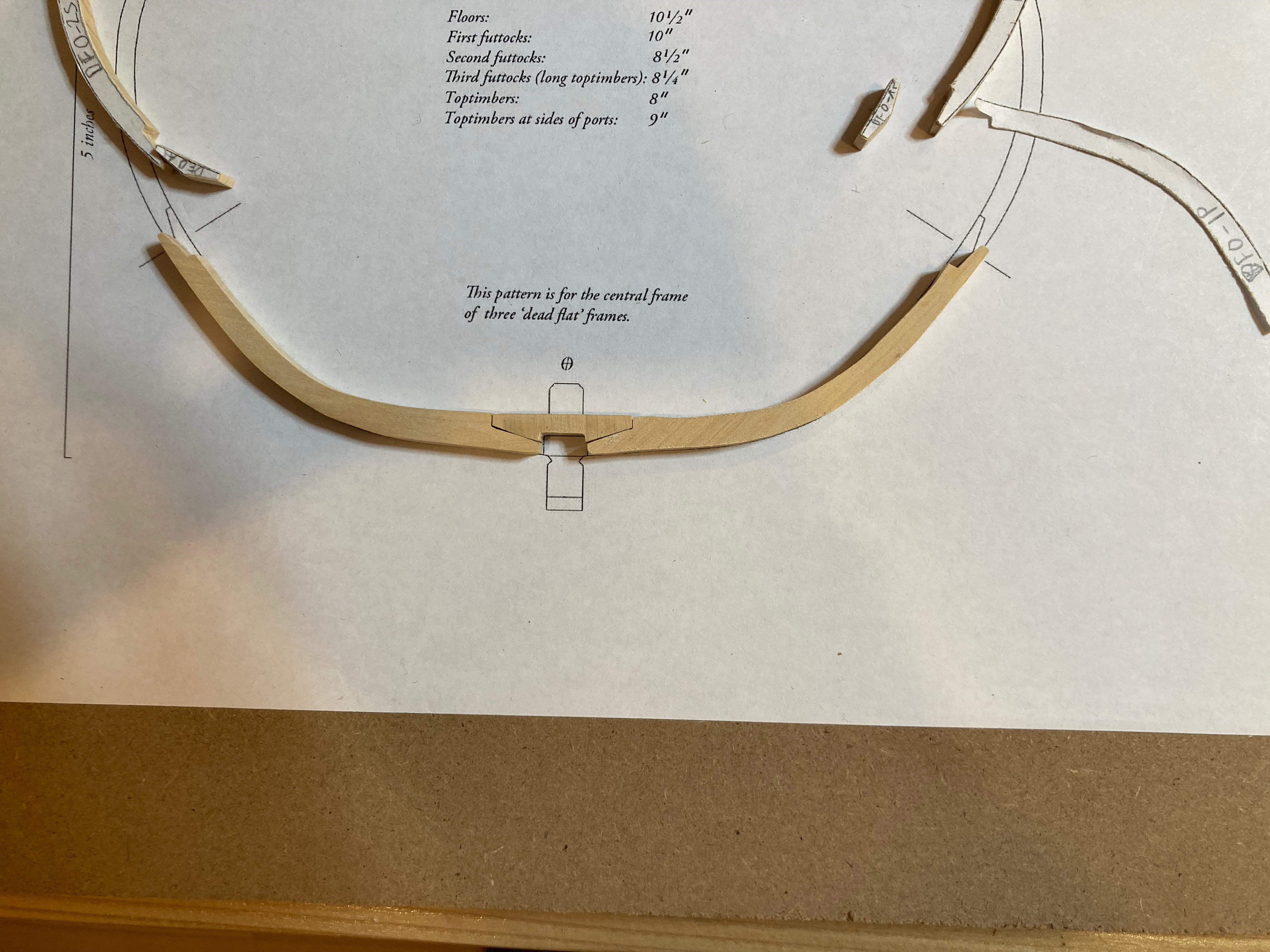
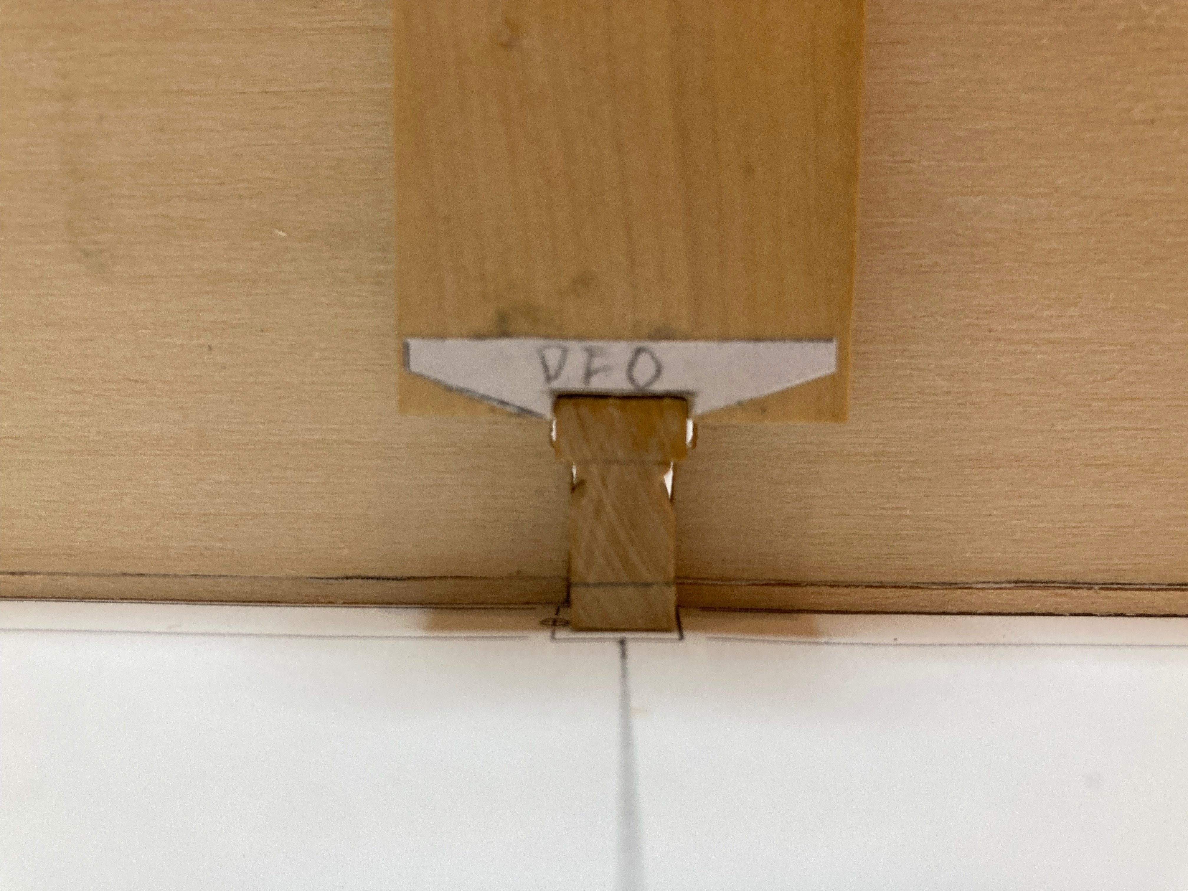
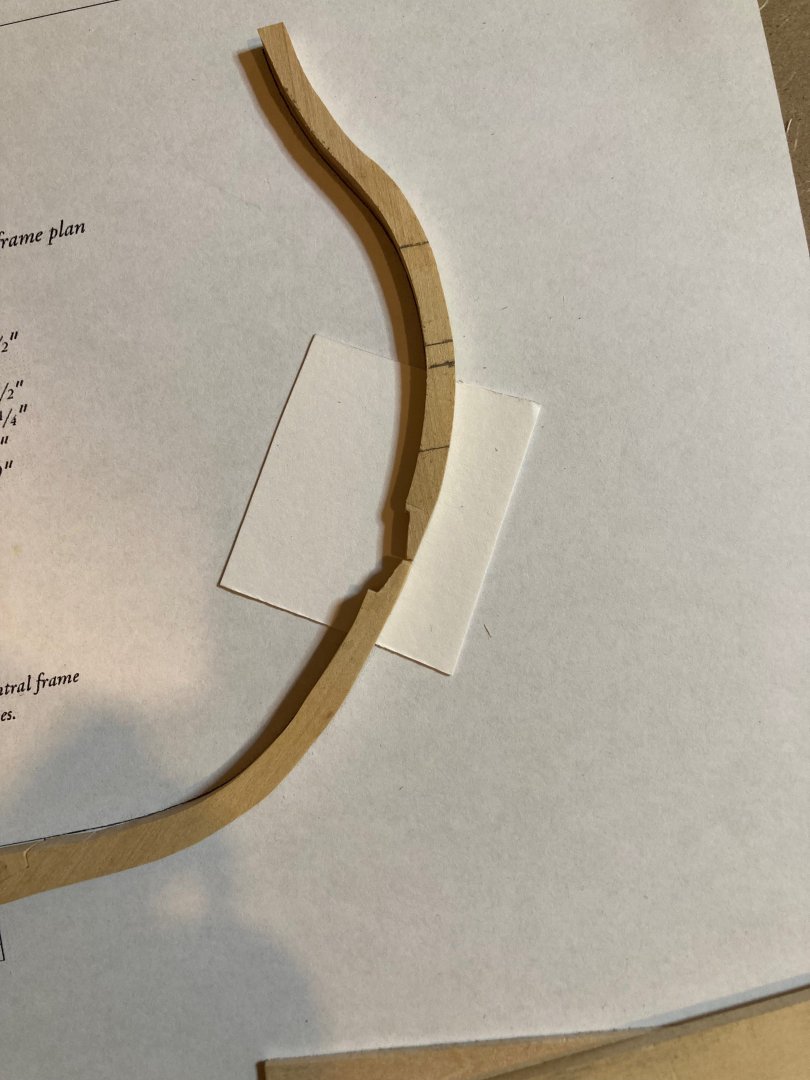
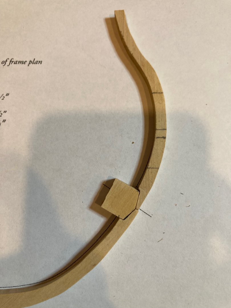
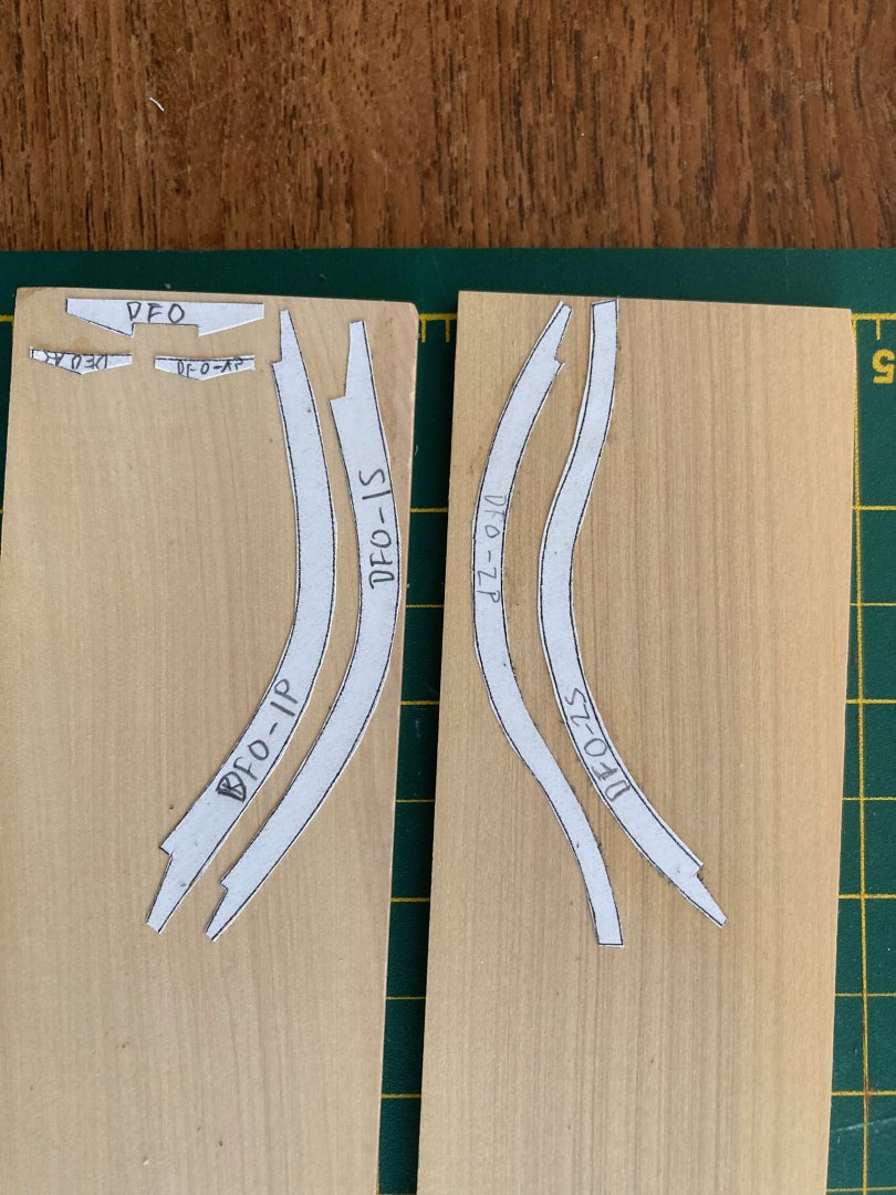
Minor update on the deadflat frame. The chocks and cross chock are now cut out and I think my approach to doing this (at least provisionally) works ok. As noted above, I made a few billets of boxwood for the cross chocks and the chocks, since I felt that it would be very hard for me to make these if I was just trying to cut them out of the larger sheets along with the futtocks. I position the template of the chock/cross chock at the end of the appropriate billets - in this case, they were all cut from 10" stock - with the angled side at 1 edge. I then use the disc sander to shave the angled portions down - not quite fully, so I can finish them off more carefully by hand with a sanding block. I then cut along the straight edge on the scroll saw to release them from the billet - I was worried that this would be really hard to achieve since the pieces are so small, but it actually proved not too difficult. Some light final finishing with sanding block and files and presto! I now only need to refine the futtocks and then get into the joinery....the kind of finnicky work that normally defeats my lazy and distracted nature, but that I'm determined to really get right! The final shot, below, shows the chocks loosely put together with the futtocks, and it shows I've got some ways still to go before I can finalise the assembly and raise the frame....but I'm enjoying this far more than I feared I might! Hopefully that feeling lasts!! hamilton

-
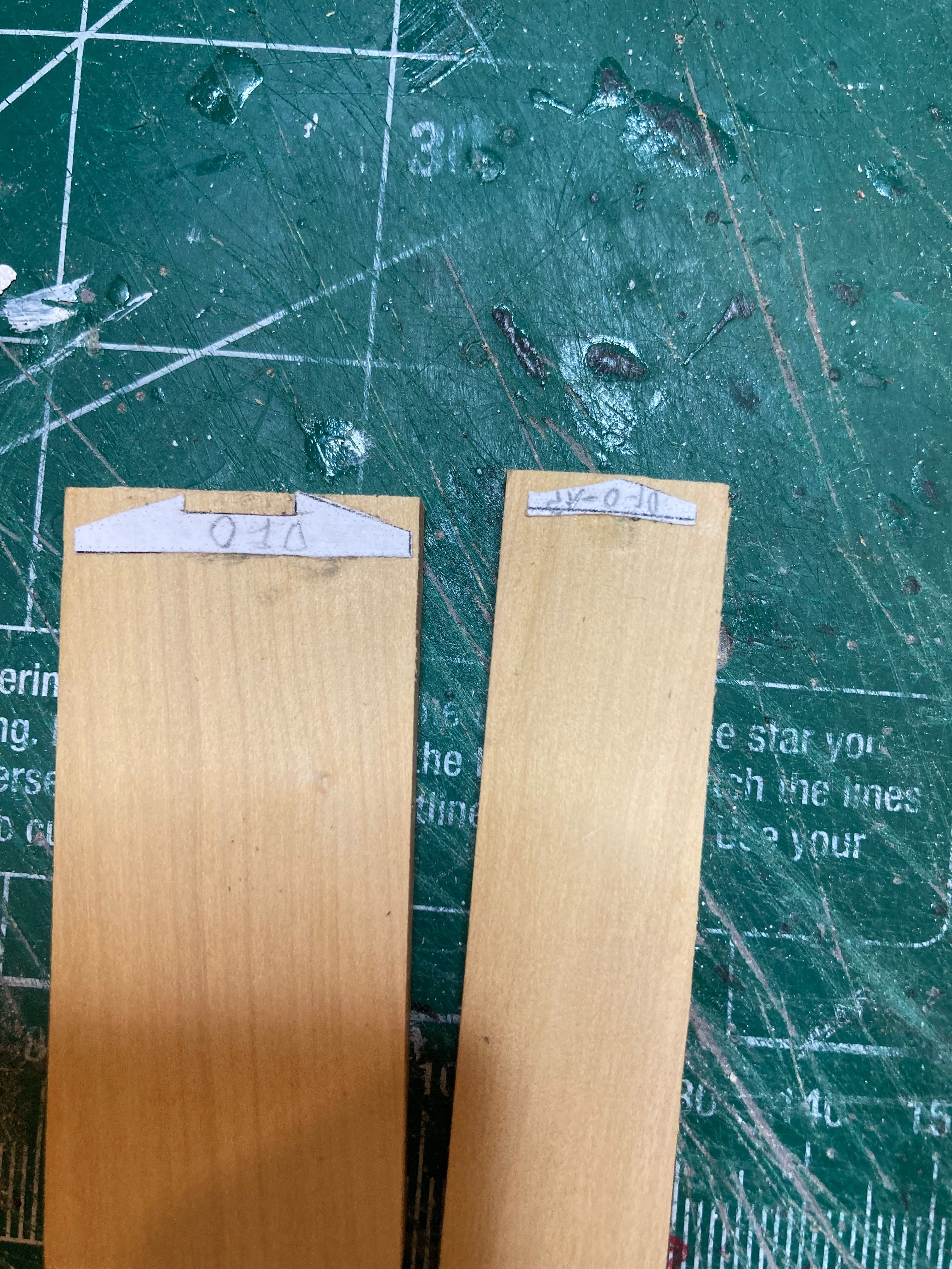
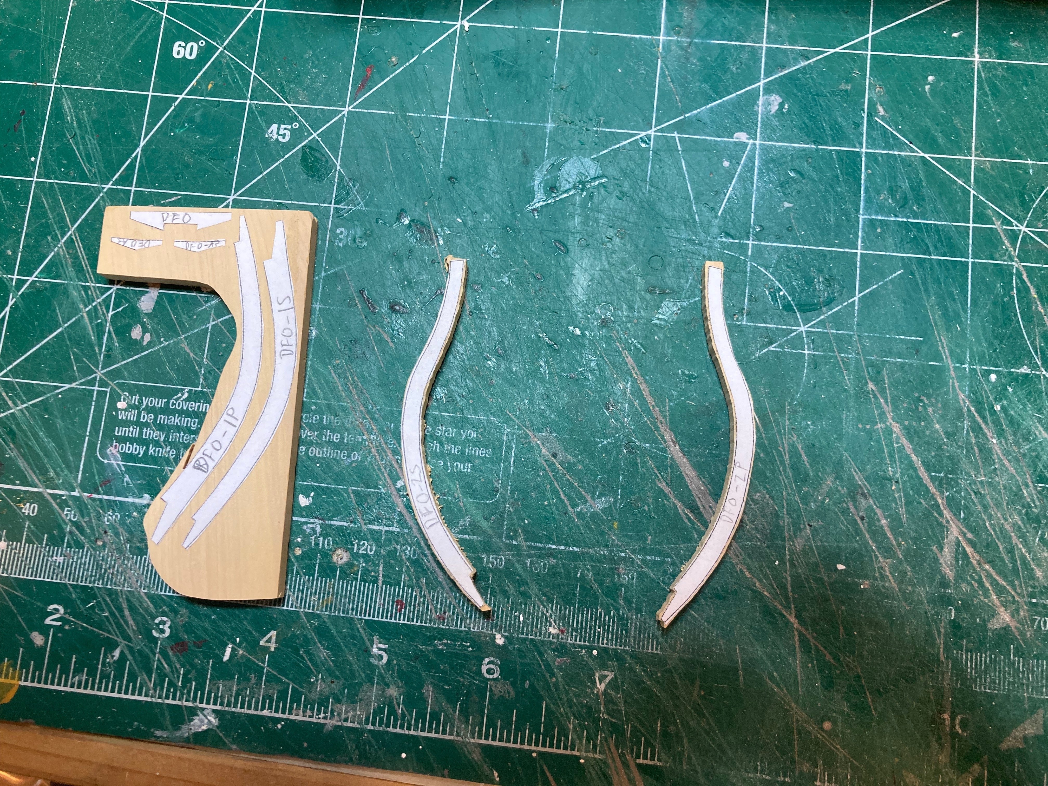
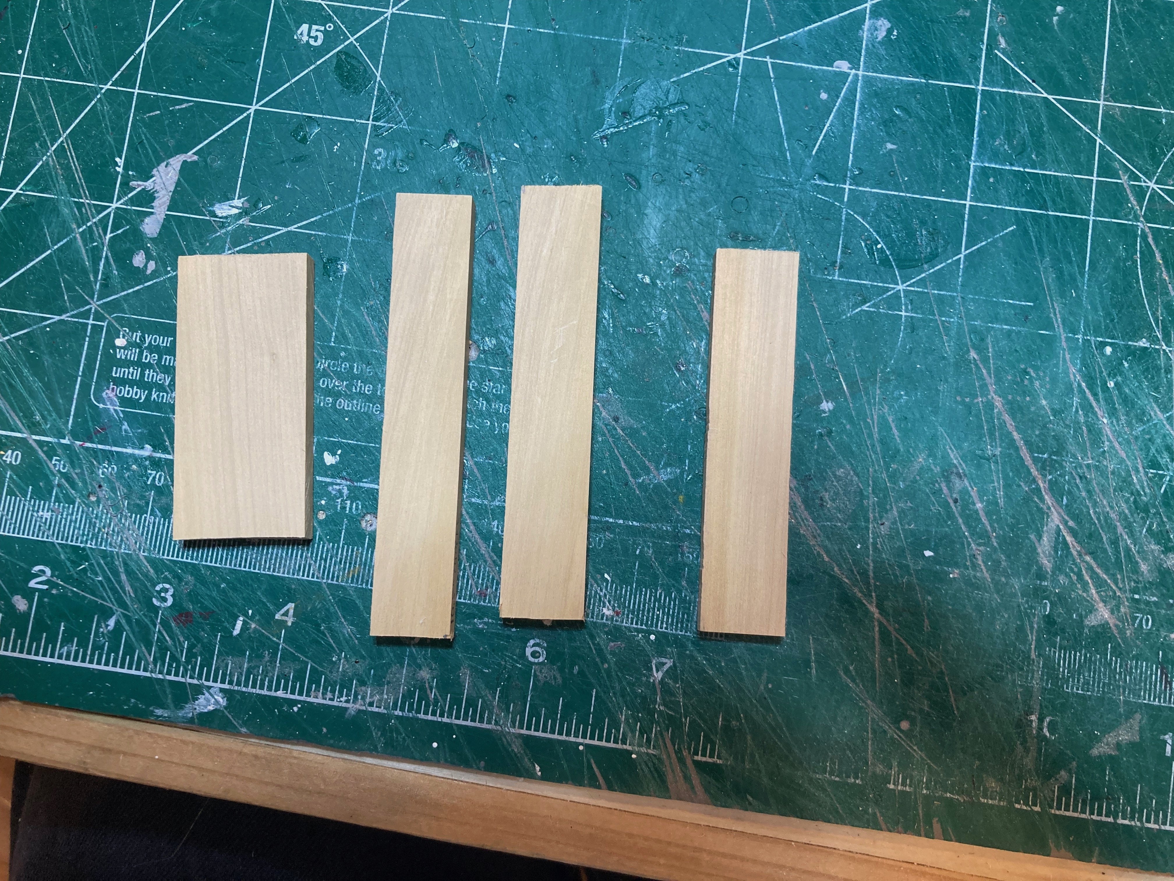
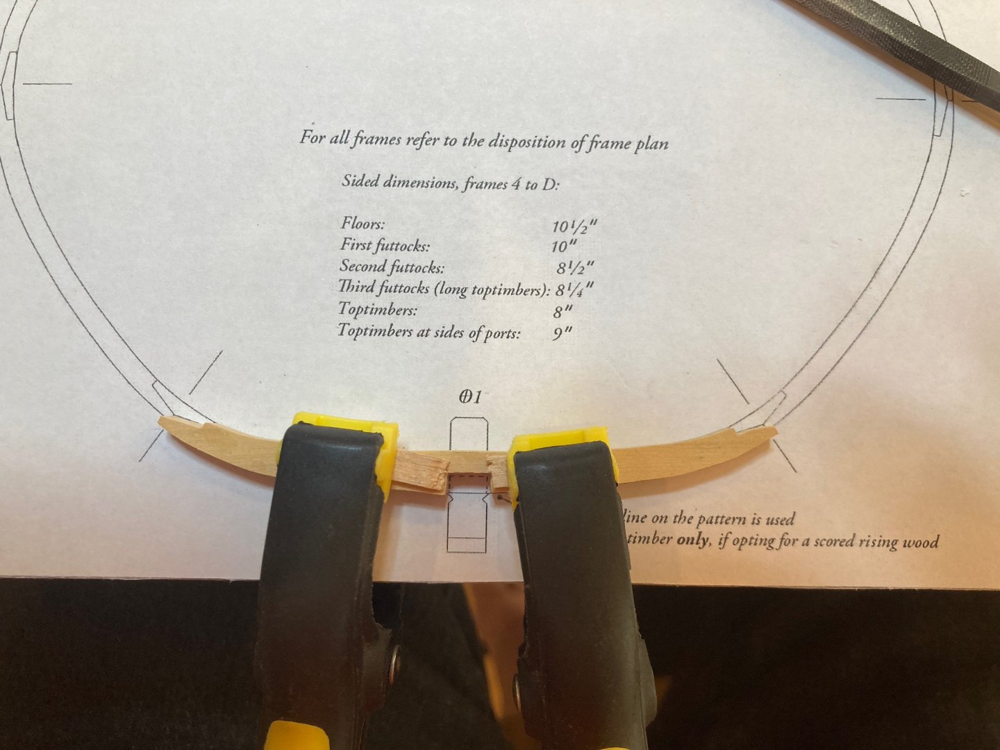
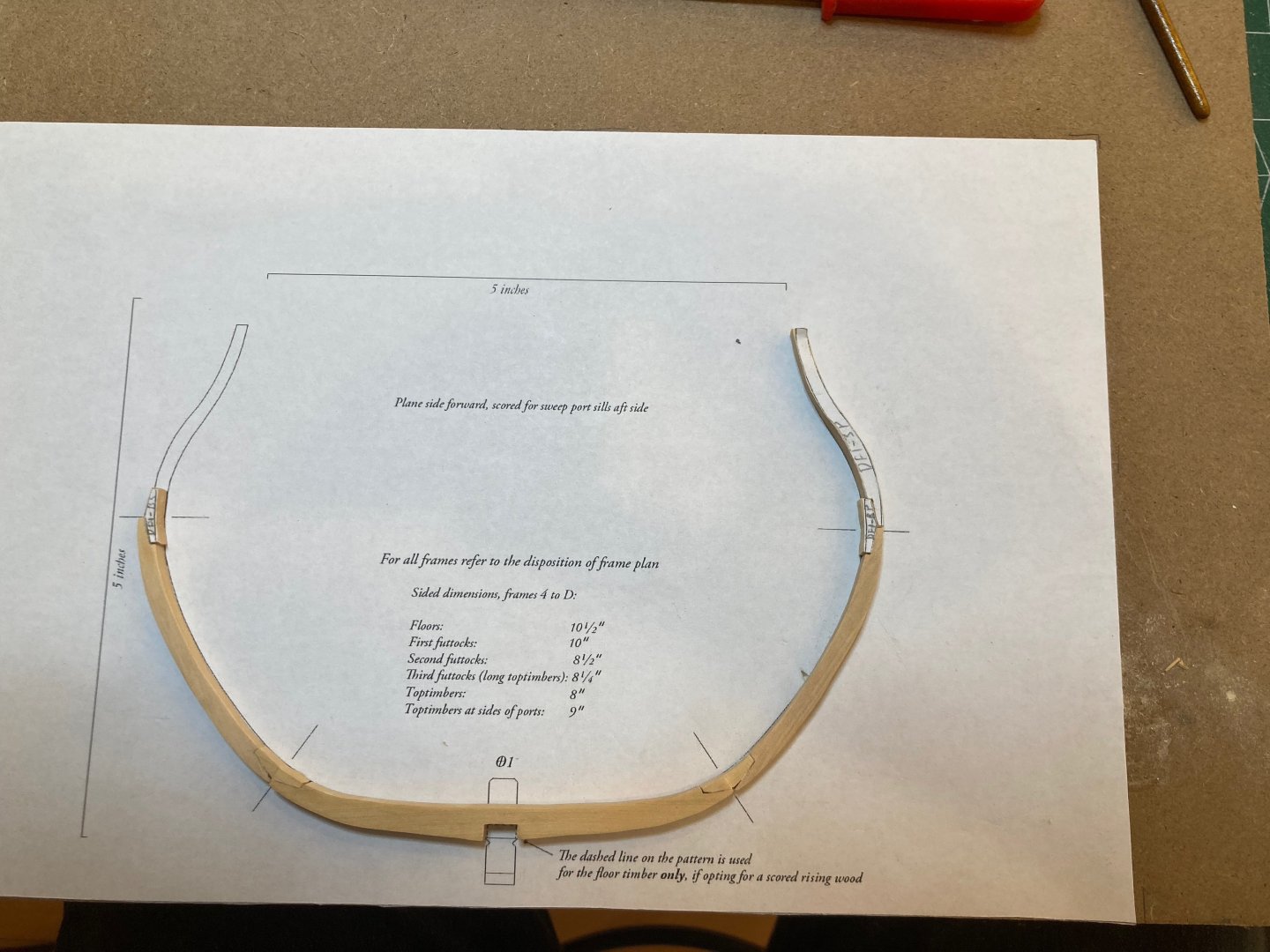
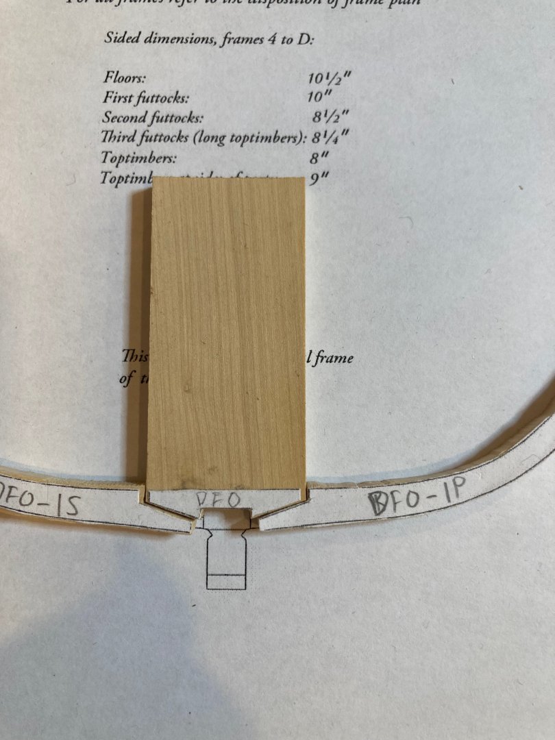
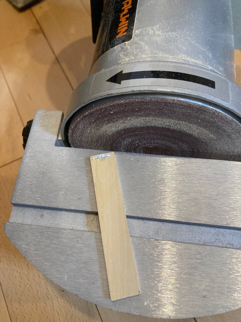
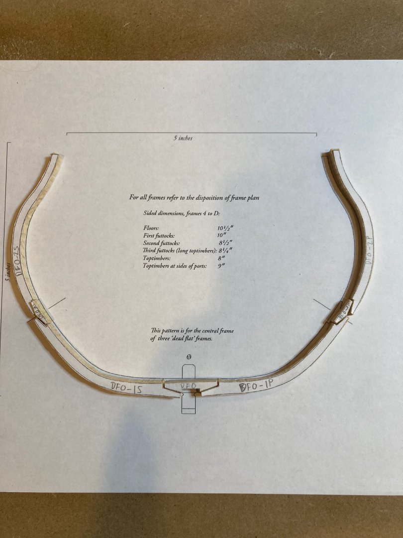
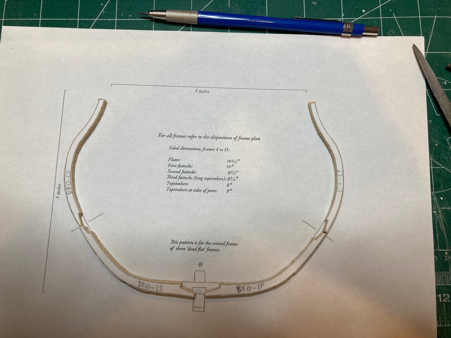
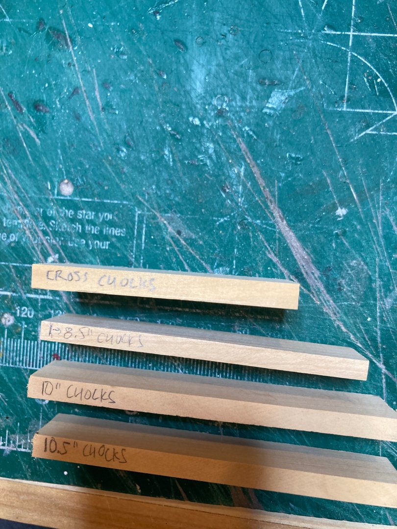
A bit more progress on Echo. I took some time over the weekend and studied the framing tables supplied by Admiralty for the cross-section, sorted through wood, made copies of the frame patterns and started work on the deadflat frame. I also made the framing square jig, the pattern for which is also included with the other documentation for this build - it is suggested to use heavy card for this, but having an ample supply of 1/16" basswood strip, I decided to use that. For the deadflat frame, I first cut out templates of the individual frame elements, but realised that cutting and refining the chocks and cross chocks might be done more precisely and efficiently if I made billets for this purpose. The chocks and crosschocks are made from different thicknesses of boxwood depending on their location - 10.5", 10" and 8.25". The cross chocks for the forward frames are all 10". So I made 4 billets - 1 10.5" x 5/8" x 3 1/4", 1 10" x 5/8" x 3 1/4", 1 8.25" x 5/8" x 2 1/4" and for the cross chocks 10" x 1 3/4" x 2 1/2". I cut these billets over long for the number of chocks required so I could use the excess as a handle to refine the angled portions of the chocks on my disc sander. The straight edge will be cut using a chisel and refined by hand. I have yet to refine the futtocks so the images below show them as I rough cut them on the bandsaw. Enjoy and bye for now! hamilton


-
Another (hopefully quick) question for you, @dvm27. I've been studying the document called "Echo Cross Section Frame Components", which provides tables giving info on the sided dimensions of frame components, and the drawing of the disposition of frame, and I think I must be missing something in relation to Frame 2 (Aft). On the Frame Components document, there is information given for the 3rd futtock (cut from 9" stock), but none given for the chock or second futtock - this is the case both port and starboard. If I read the table correctly, I'm to attach the 8" 3rd futtock of frame 2 to the 10.5" floor of frame 2 directly using a 10.5" chock - is this right? I know this frame is line with the gunport, so perhaps that explains things. But when I checked this against the disposition of frame drawing, I noticed that a) there are 2 measures given on the 2nd futtock - 8.5" in the lower part and 8" at the upper part - I assume this indicates a taper, rather than two futtocks, since there is no line dividing a 2nd & 3rd futtock as can be seen in the other aft frames.....is that right? Thanks for any clarification you can provide - I hope my explanation of the problem I'm having is clear..... hamilton