niwotwill
-
Posts
596 -
Joined
-
Last visited
5 Followers


About niwotwill

- Birthday 02/10/1942
Recent Profile Visitors
2,699 profile views


-
 CiscoH reacted to a post in a topic:
HM Cutter Cheerful 1806 by niwotwill - Syren Ship Model Company - scale 1:48
CiscoH reacted to a post in a topic:
HM Cutter Cheerful 1806 by niwotwill - Syren Ship Model Company - scale 1:48
-
Freebird reacted to a post in a topic:
HM Cutter Cheerful 1806 by niwotwill - Syren Ship Model Company - scale 1:48
-
davyboy reacted to a post in a topic:
HM Cutter Cheerful 1806 by niwotwill - Syren Ship Model Company - scale 1:48
-
KORTES reacted to a post in a topic:
HM Cutter Cheerful 1806 by niwotwill - Syren Ship Model Company - scale 1:48
-
KORTES reacted to a post in a topic:
HM Cutter Cheerful 1806 by niwotwill - Syren Ship Model Company - scale 1:48
-
Ryland Craze reacted to a post in a topic:
HM Cutter Cheerful 1806 by niwotwill - Syren Ship Model Company - scale 1:48
-
AJohnson reacted to a post in a topic:
HM Cutter Cheerful 1806 by niwotwill - Syren Ship Model Company - scale 1:48
-
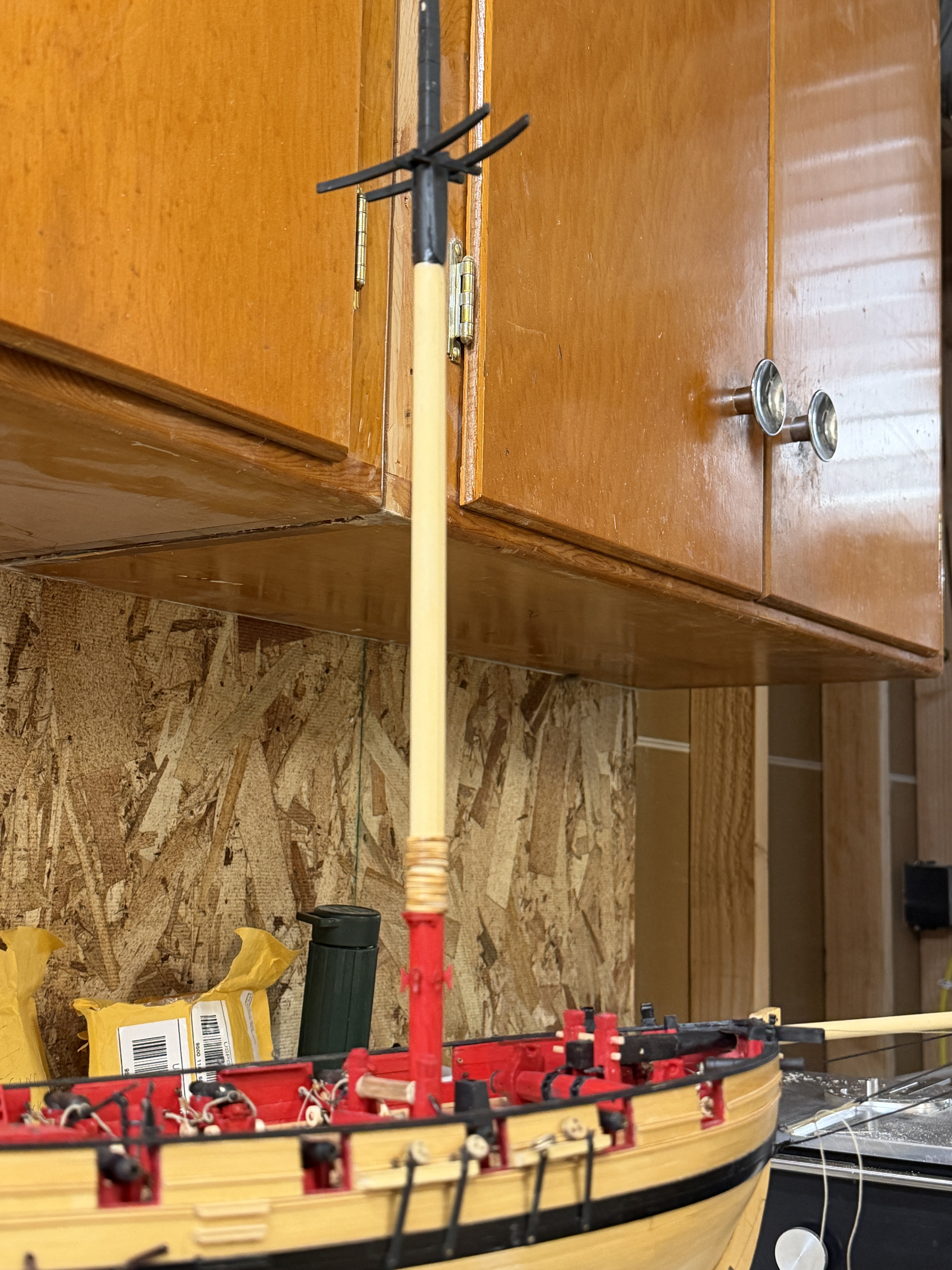
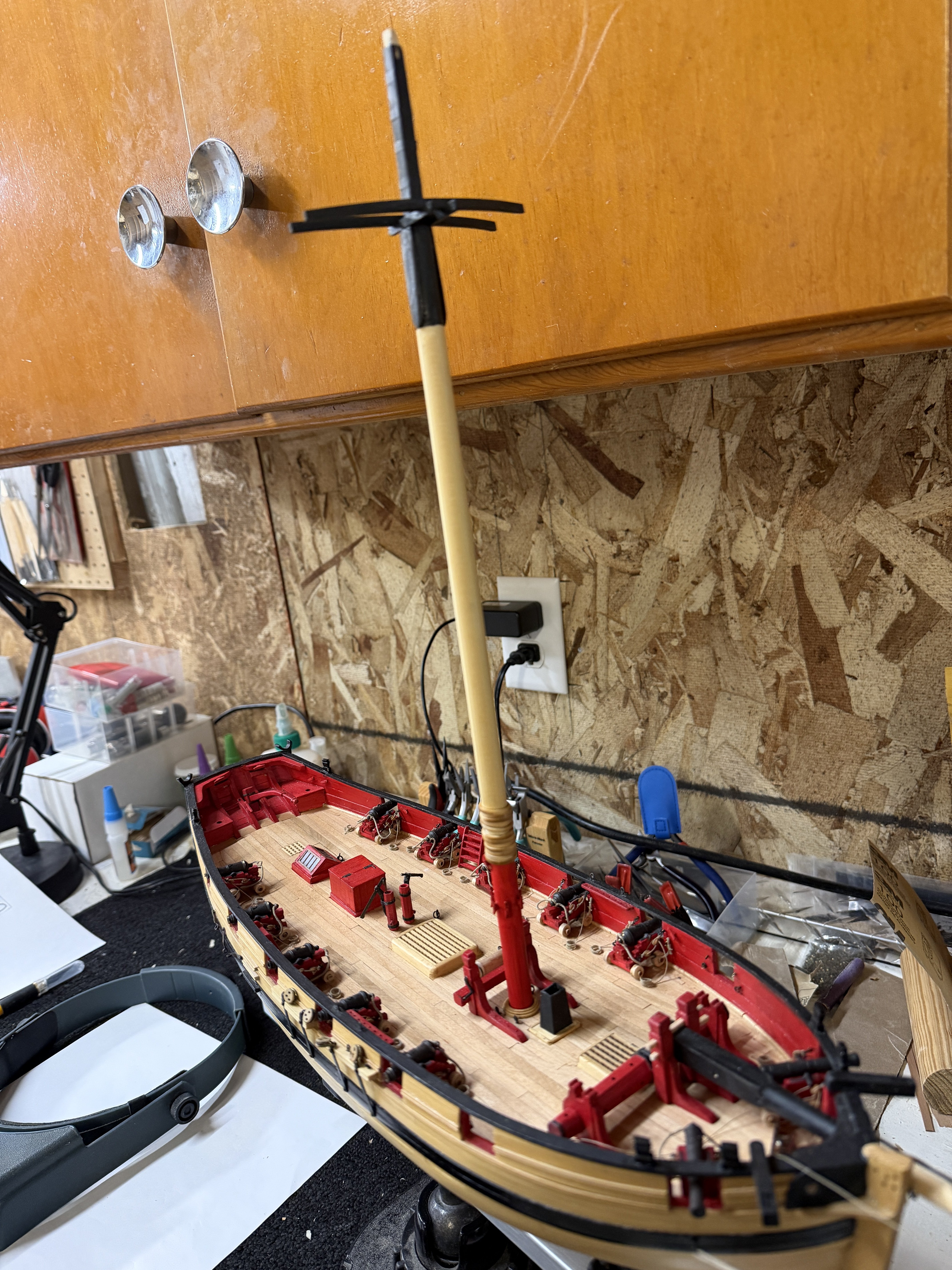
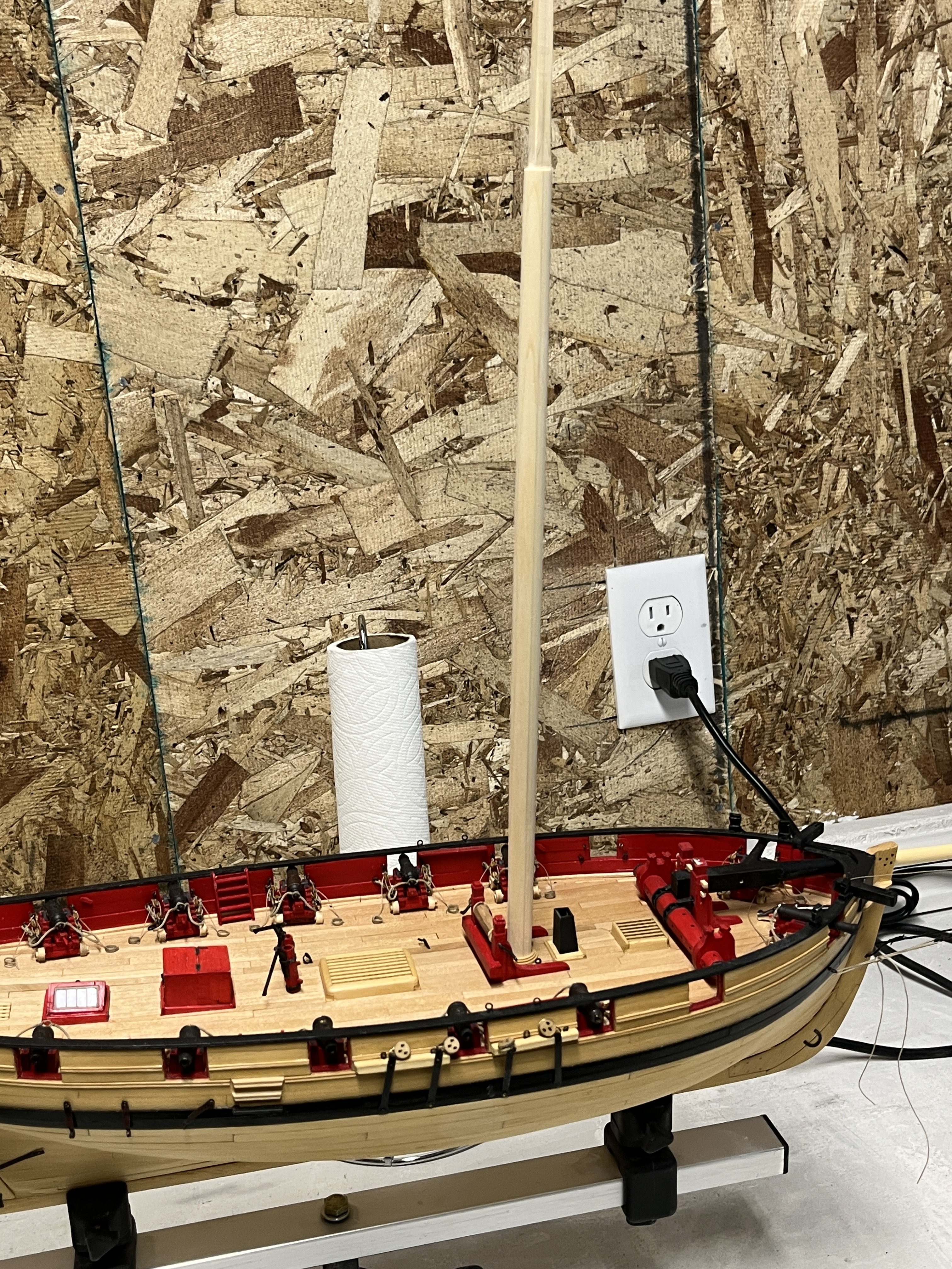
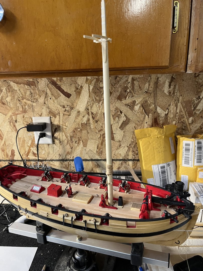
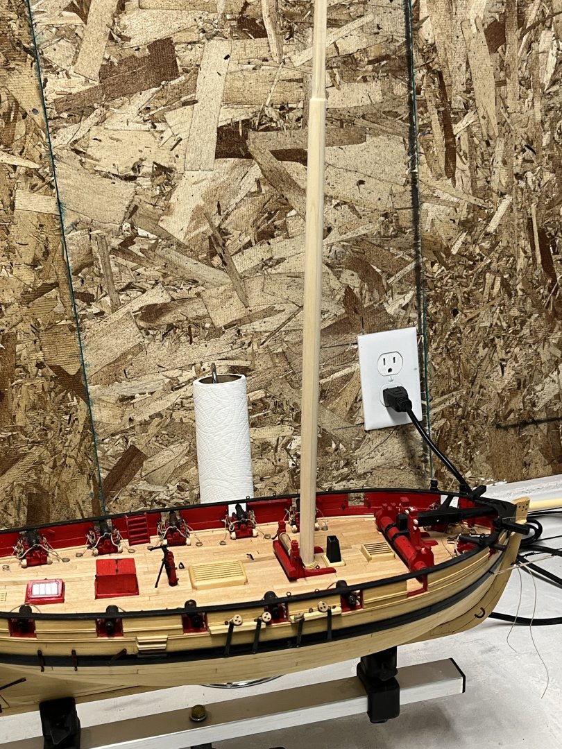
 Lower mast was completed last night so now on the to the upper mast and not much to report except how good it looks. No work today except for taking down the Christmas tree and decorations ending the season.

-
Freebird reacted to a post in a topic:
HM Cutter Cheerful 1806 by niwotwill - Syren Ship Model Company - scale 1:48
-
davyboy reacted to a post in a topic:
HM Cutter Cheerful 1806 by niwotwill - Syren Ship Model Company - scale 1:48
-
AJohnson reacted to a post in a topic:
HM Cutter Cheerful 1806 by niwotwill - Syren Ship Model Company - scale 1:48
-
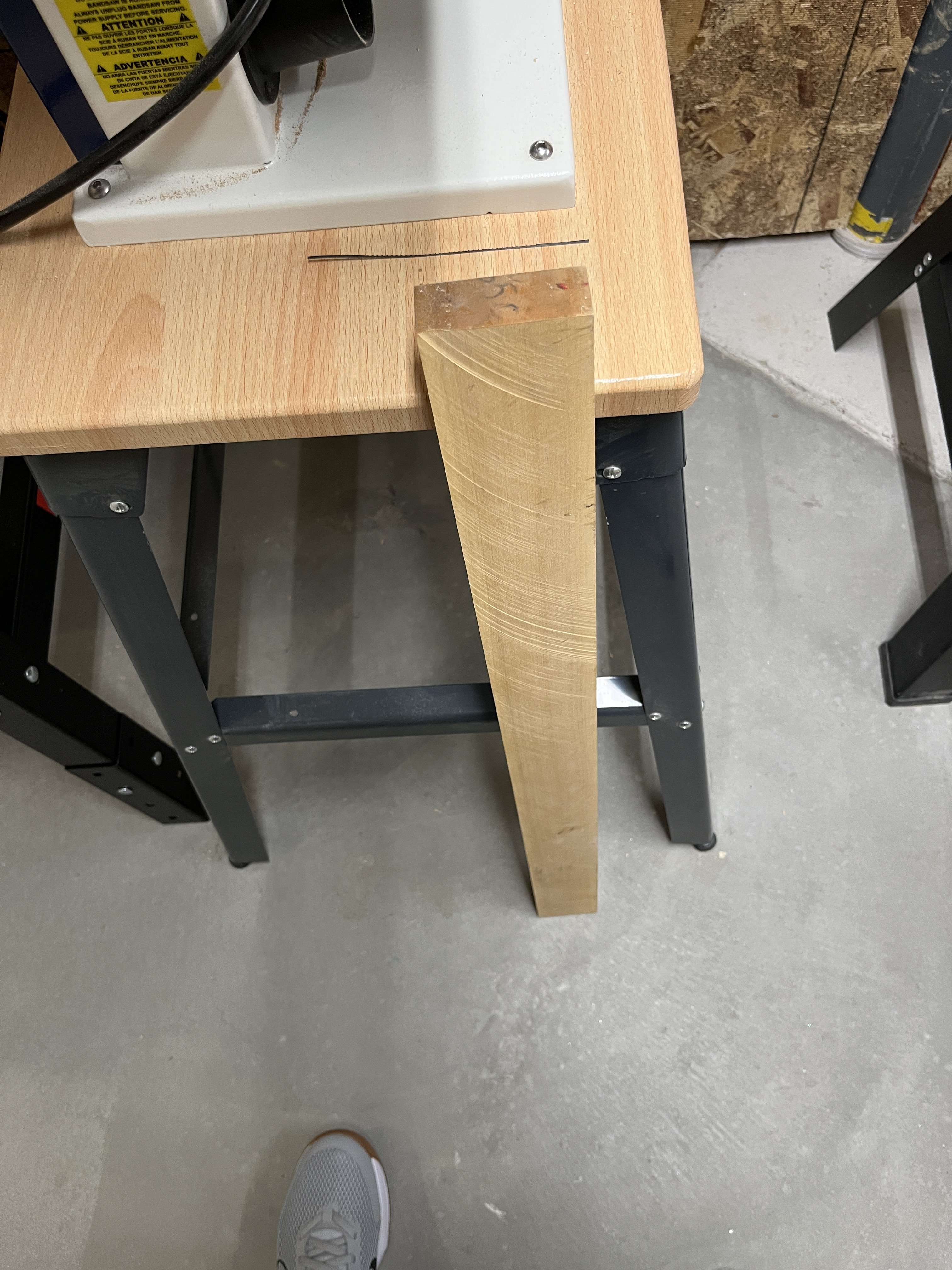
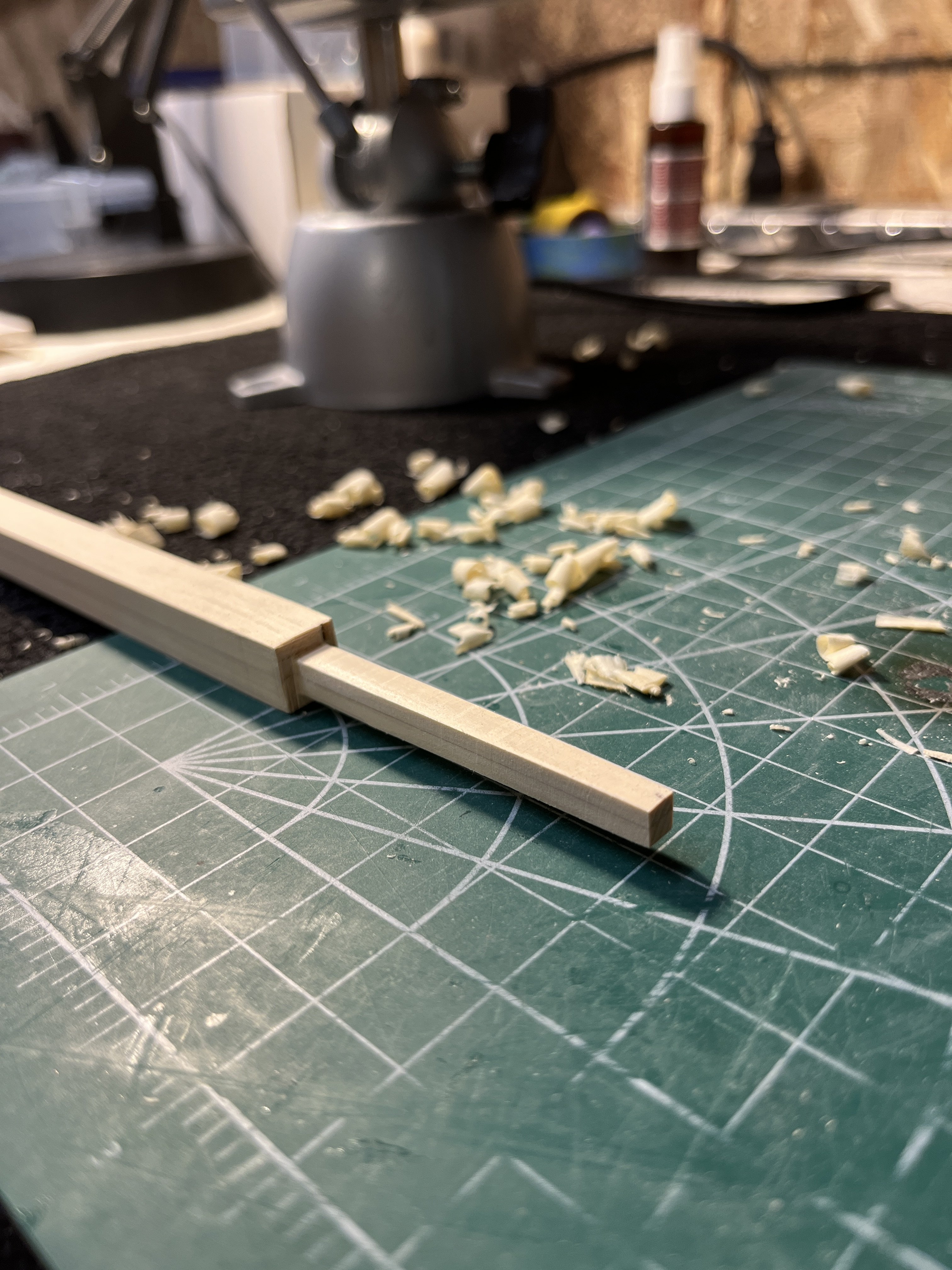
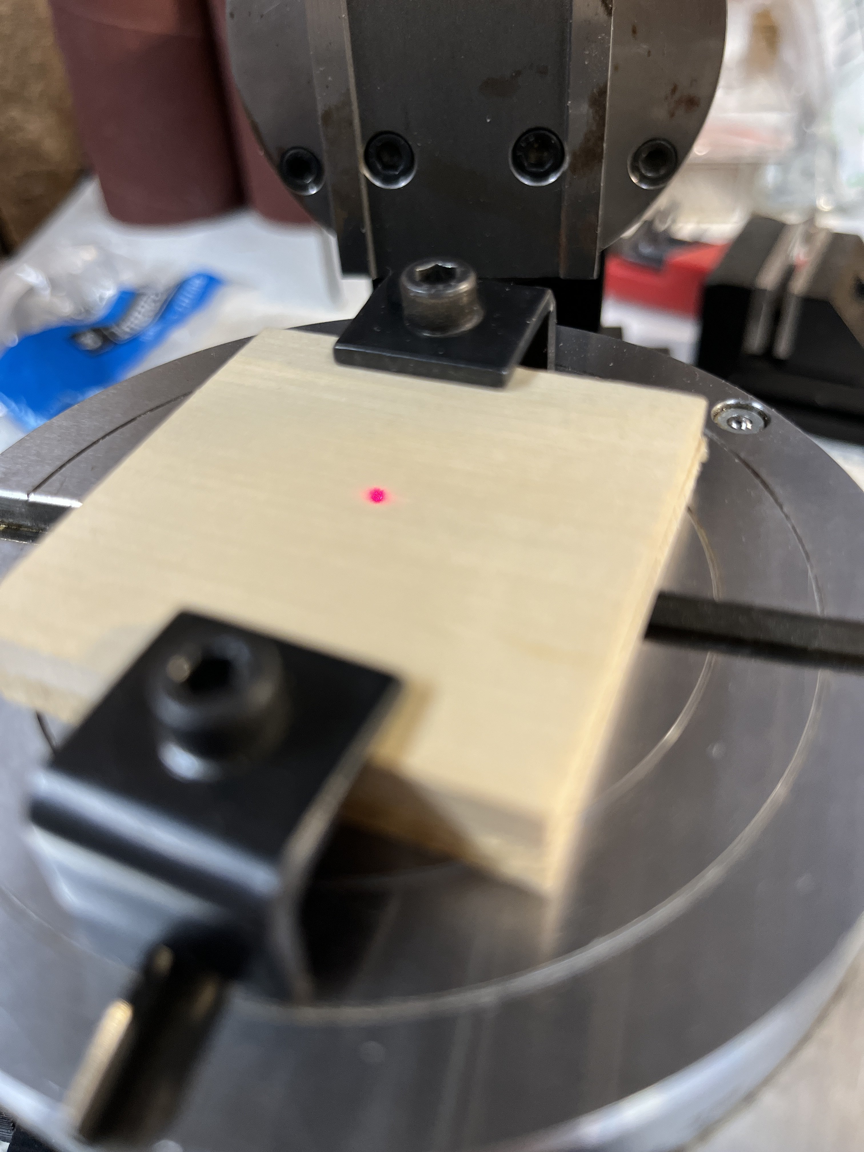
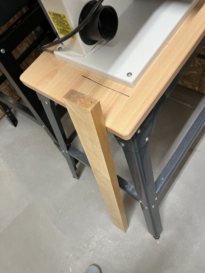
Now where was I? Oh yeah I needed to make the lower mast. Started out by finding I didn't have the wood. Needing a 5/16" thick AYC or boxwood which I didn't have left me two choices 1) ripping boxwood plank n wasting a large piece of wood for such a small part or glue two pieces of 5/16" together after ripping and cementing together making a 5/8" for the mast . Using the Byrnes sander making a piece 5/16" square r Ready for the square portion of mast Next using the 7/10/7 method to make an octagon ready for the lathe. using plane cutting to the marks and into the lathe into the finished mast


-
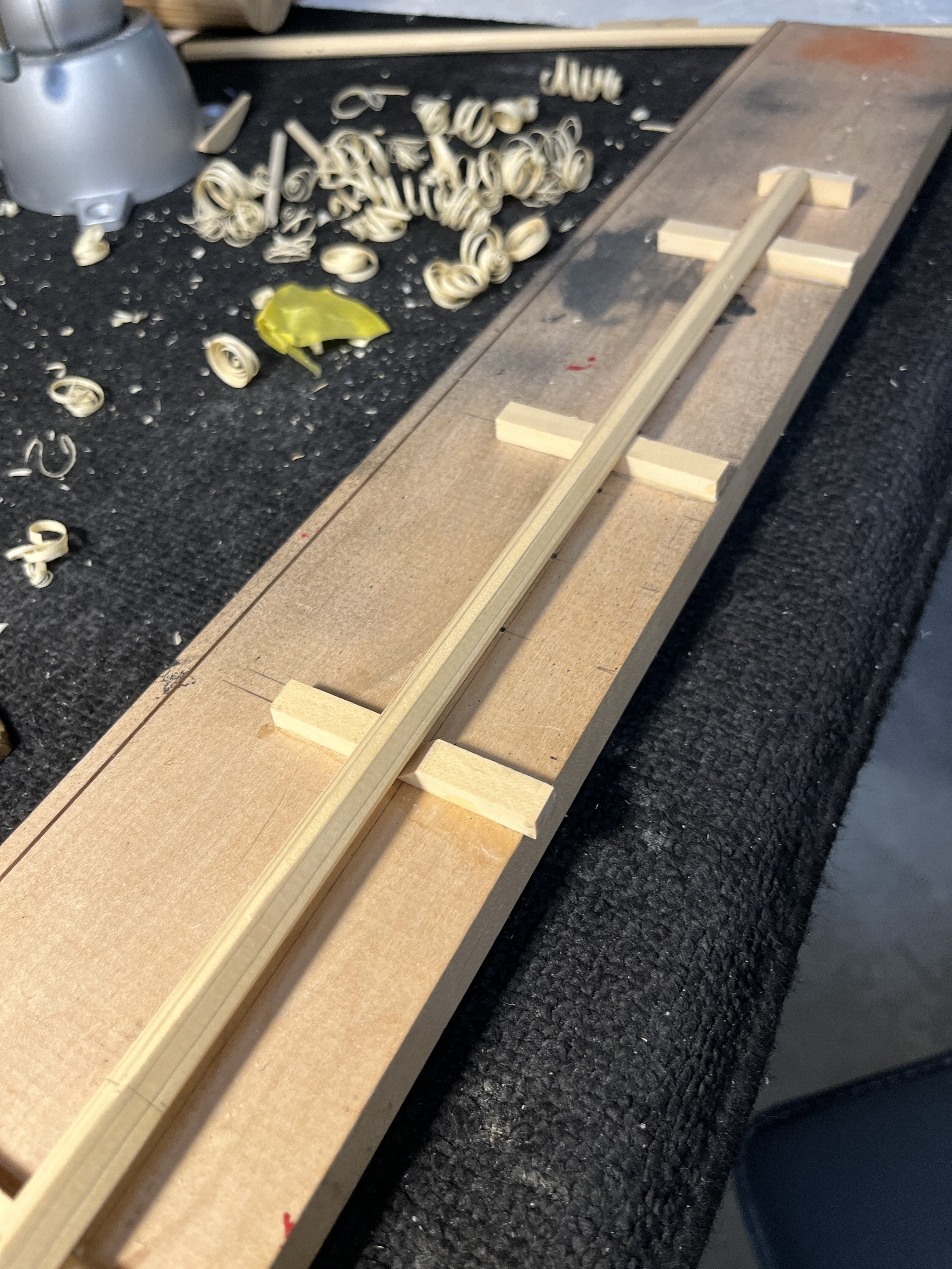
First batch of birthdays and holidays (Wife's on 10/22, Brothers on 12/6) behind me so now on to the Cheerful. Worked on the trees before the mast as I think it will be easier to make the mast fit the trees rather than trees fitting the mast. I copied the plans and glued to wood for part. Using the scroll saw cutting the image leaving enough too finish with the disk sander. (I'll put a new sandpaper) next using the oscillating spindle sander to finish the parts inner curve. Like other logs where the used a mill to cut the slots into the cross pieces, why with others success why reinvent the wheel, I did the same process. Using four pieces of material glued together so the protecting the inner pieces from chipping as the cutter existed. T The parts where assemblied on to of the plans image. I left the center cross piece long on purpose to file it close to the adjoining part. When the glue dries I sand the center flush to the sides. With to trees done I'll move on to the mast. Gulp


-
Just thanking everyone for following my Cheerful log with all the comments and likes.
-
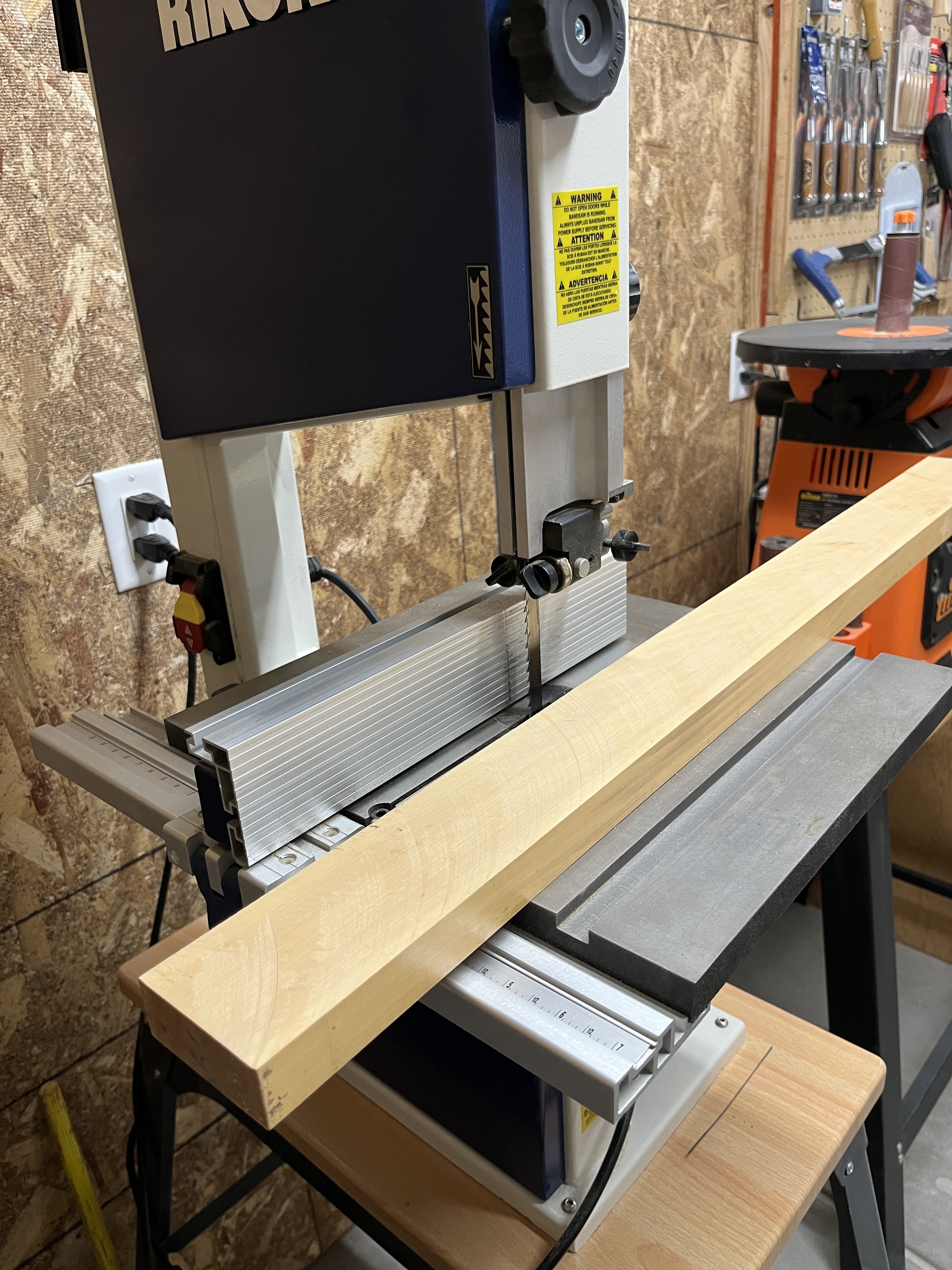
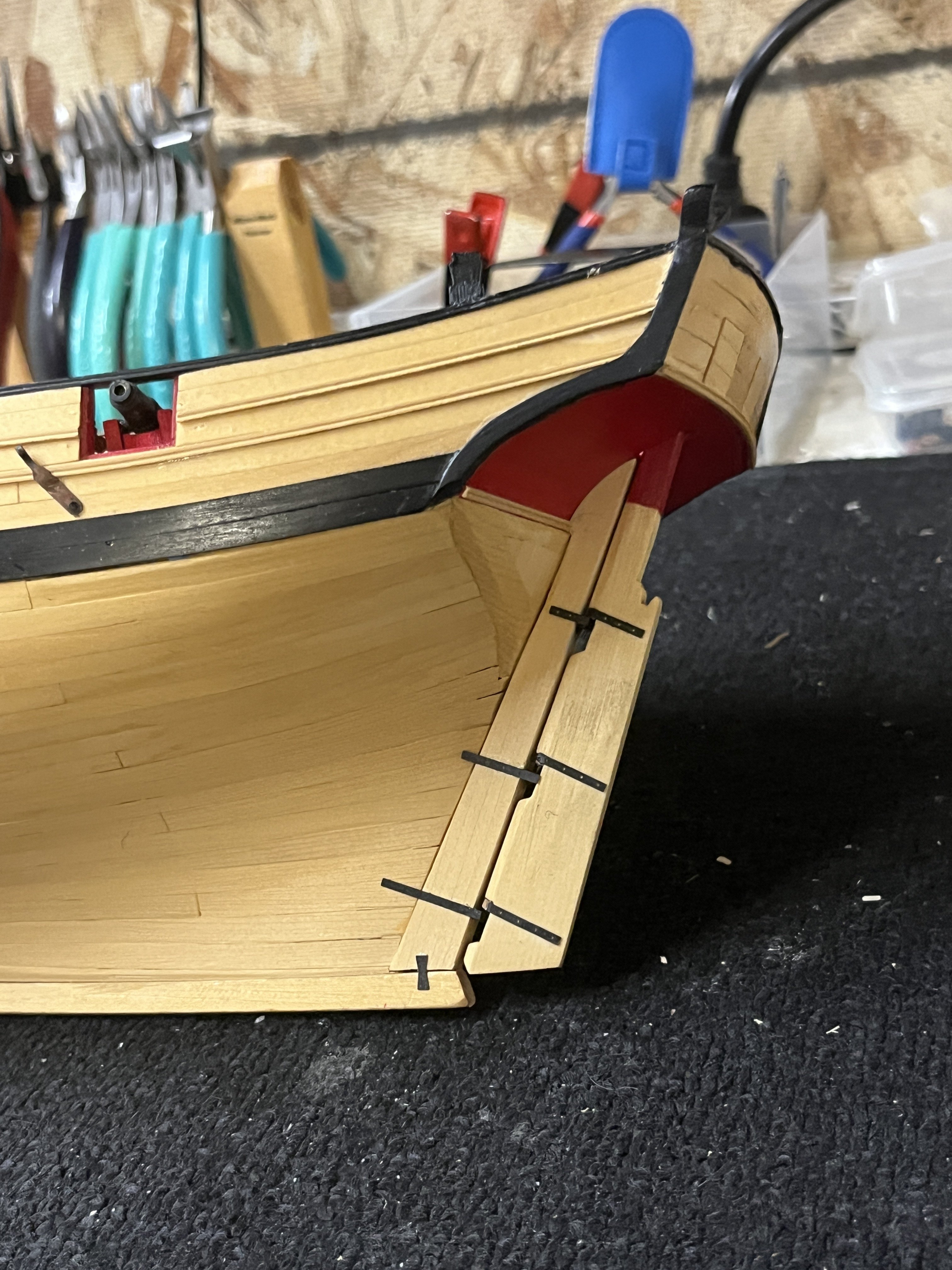
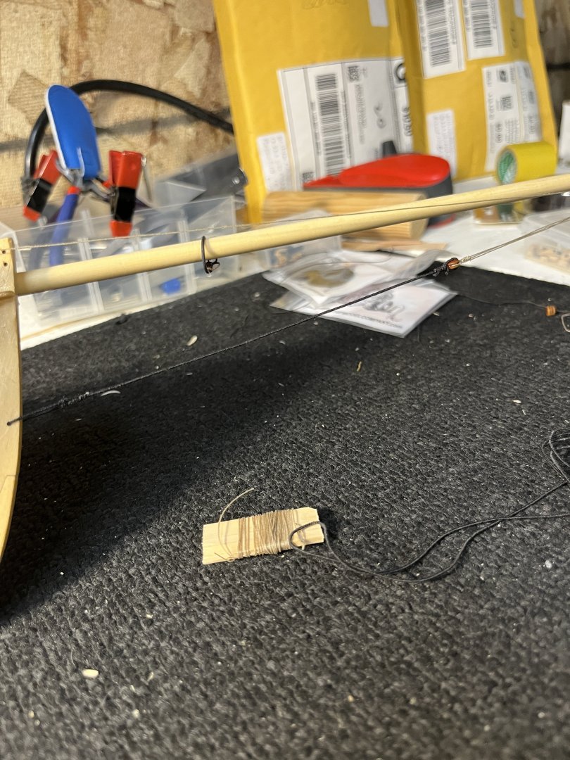
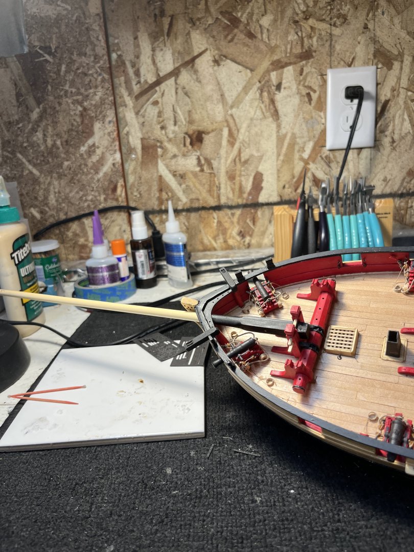
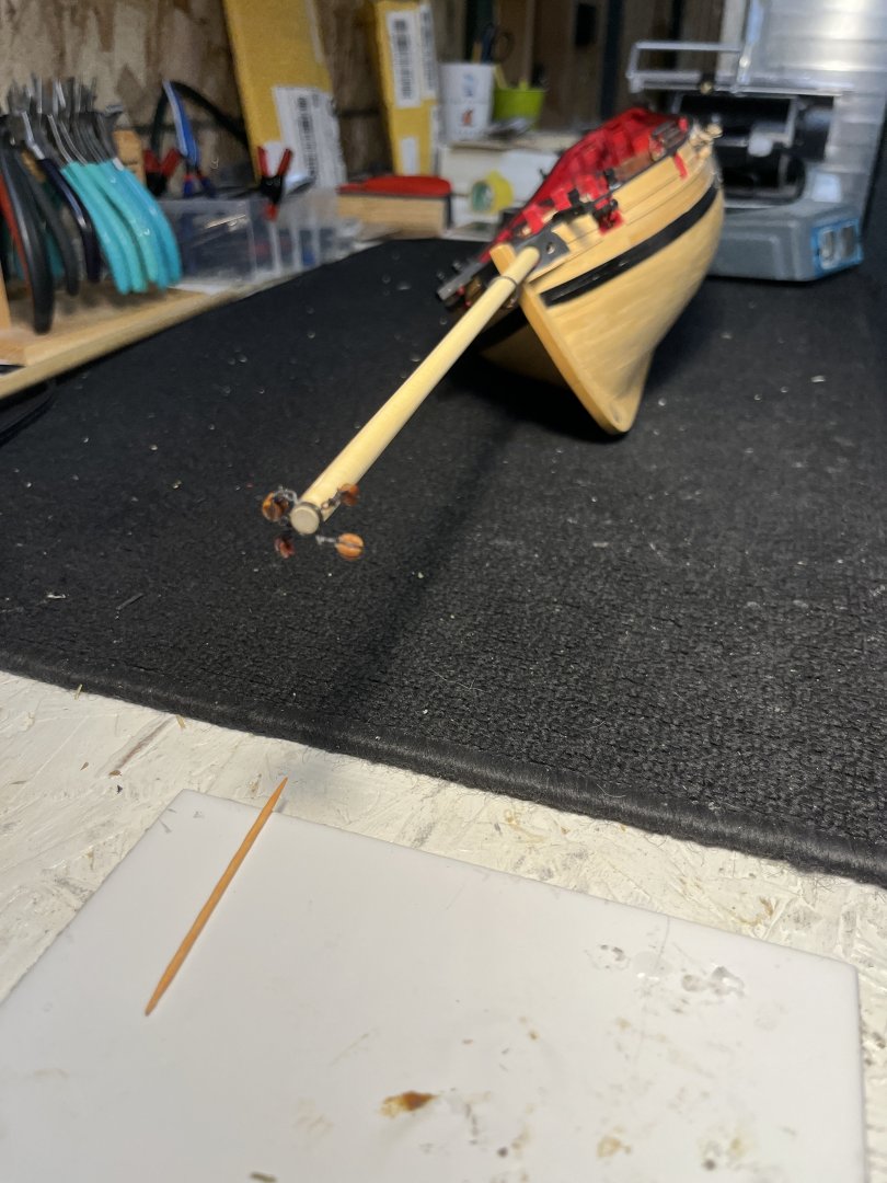
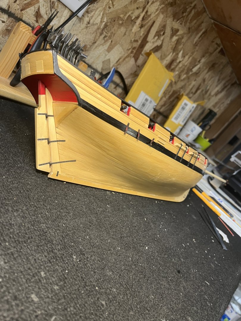
Finishing the bowsprit by adding the simulated sheave added at tip. Placed the bowsprit in my Proxxon lathe tapering from the square section to the tip. While in the lathe I filed tip with a small file. The metal (simulated) band was added to tip with 4 holes for the blocks. That all done I had to carefully finagle the blocks through the hole. Adding the bowstrip step and aligning such that the square rod could be pushed into the square hole. Now the posttion of the bowstrip and winch could be determined I glued them in position. This done I started the rigging process first the bobstay tackle and bobstay guys were rigged. Now with this done lets move on to lower main mast. I didn't have a piece of wood long enough so I have a slab of boxwood that I planned to use on 1776 Washington Galley later but that will be later. Next more about ripping the slab to make the beginning of the lower mast. Its been quite awhile since I ripped wood on my band saw so Its too late starting a long process so I leave it until were home from Thanksgiving with friends in Phoenix. I had bought several of these boxwood slabs from the Gilmorewood company in Portland, Oregon. Its hard to cut into a slab to used in another project for one mast but It is for a good use and I have more.


-
Thanks Glenn for the suggestions. Looking at the rigging of the boom I see why you suggested and why. Thanks to all who looked and commented on the Cheerful to date. Chapter 11 complete up to bowsprit and mast shape wood Bowsprit and mast rig bowsprit rip wood for the mast finish mast touch up paint use drafting compass to draw 7/1/7 lines on wood r Shaping after squaring and drilling holes Add metal band at the tip with four blocks seized to the rings file hole in bulwarks to fit the bowsprit touch up paint On to the mast


-
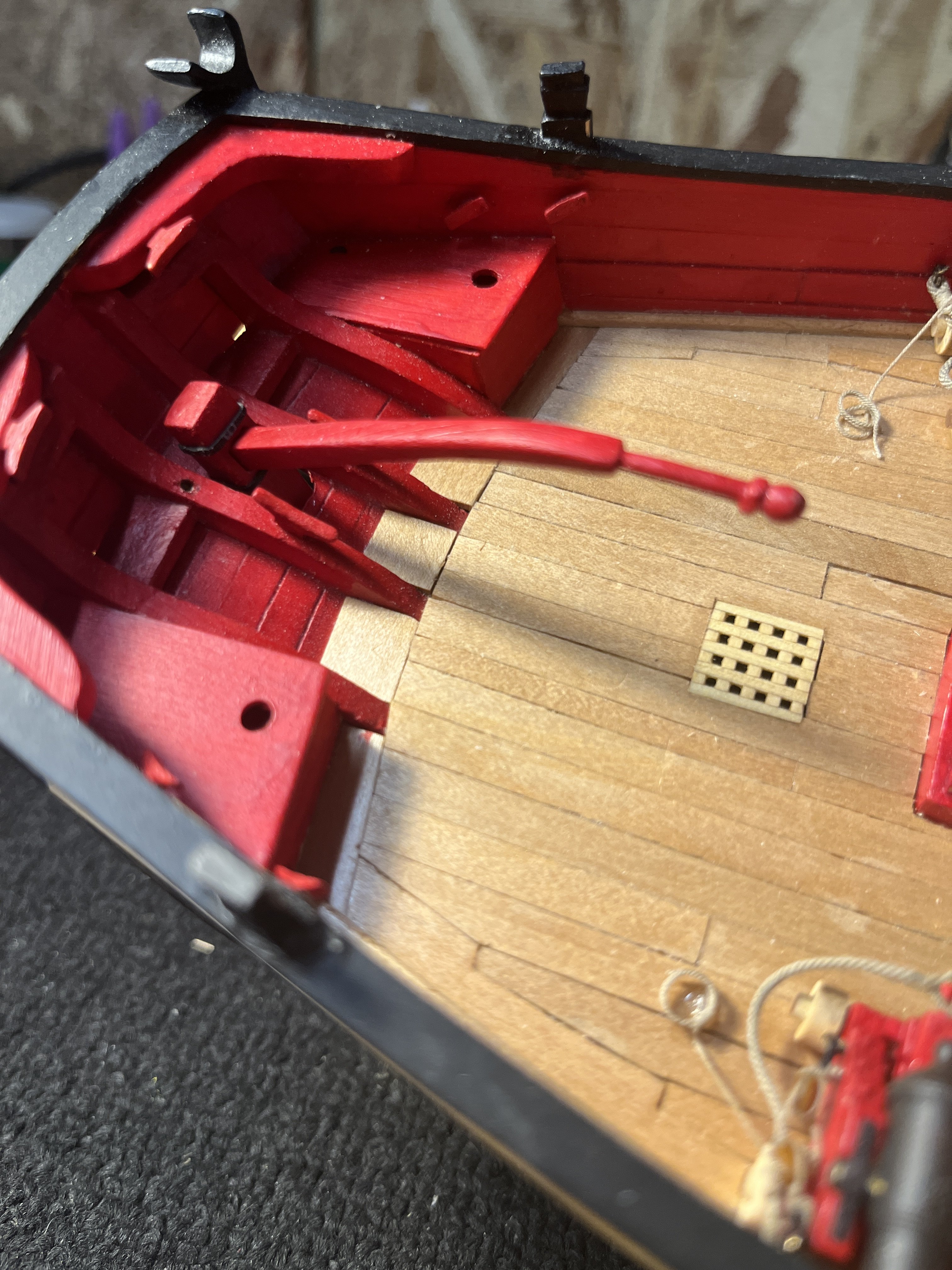
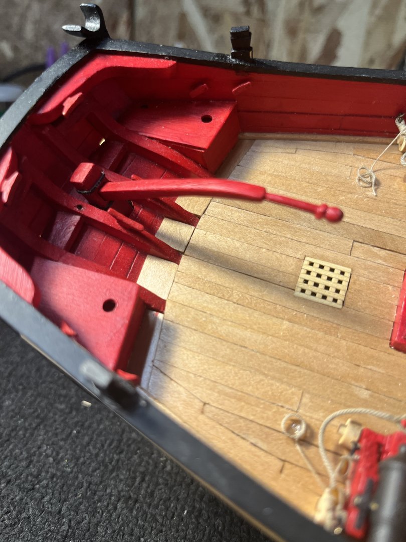
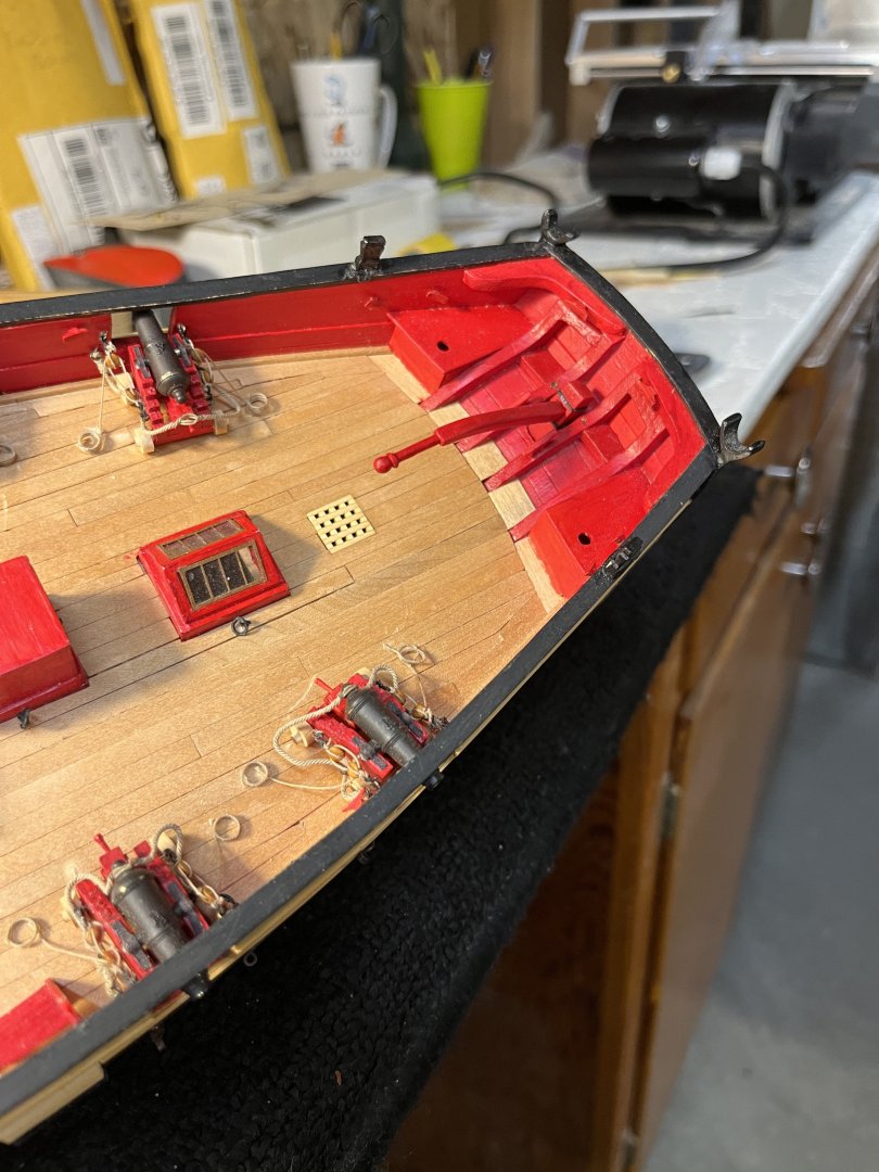
Chapter 11 consisted with the deck furniture previously recorded plus the rudder and tiller. The rudder had quite burn scar from laser cutting. Once the rudder was clean I followed the monograph with the side tapering. Thinking I would make the gungeons and pintles out of brass soon appeared to be more difficult than I had thought. All the curves on the hull were difficult to conform with the .015 brass. So back to the Syren kit for pintles and gungeons which was than I first thought. Going back looking at the pictures I noticed the nails were omitted. For another date after the mouth heals. Knowing that tiller would need to fit ahead rectangular hole I followed the suggestions in the monograph cutting a rectangular hole for tiller. The rudder and tiller were easier than many on the Cheerful. I panted and dusted the parts prior to gluing. Being carful noting glbarlow warning of parts not sticking due to many layers of wop. With the rudder hung it was time to make the tiller. Using 1/8" material and shaping the end so that it fits snuggly between the simulated metal bands on the rudders head. On another site I saw how a metal rod was used for gungeon alignment allowing free rudder movement after rudder pintle pins slipped into the gungeons.

-
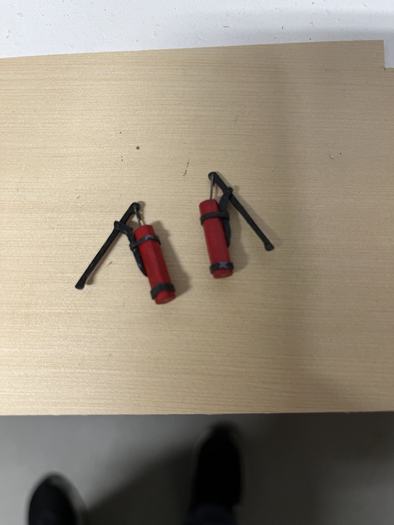
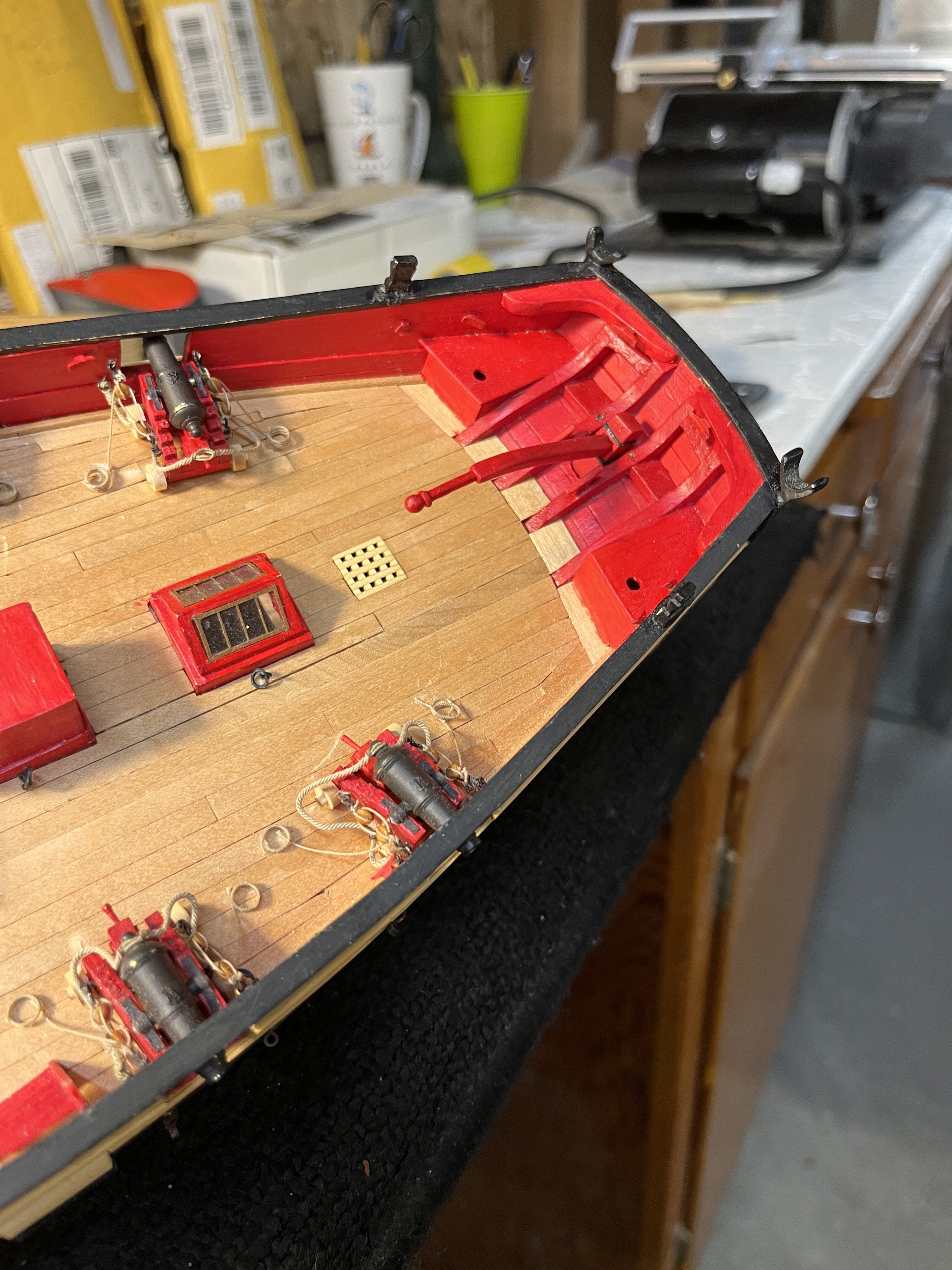
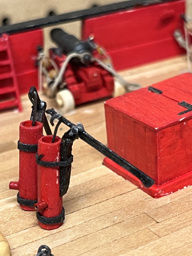
Nov 18th and the deck furniture made while on vacation June 2021. So to follow the build refer to sheet 2 of this log. The pumps made using Syren Model kits. I made the exhaust ports from brass tubing. You'll notice one of the pump handles broke when the plunger installed. Had to make a new handle and smaller wires. More Syren kits companion way, bowsprit, and winch. These kits are amazing not only in their quality but they give a very nice break for the slower tasks. Bowsprit completed but not glued to the deck. The winch completed but again not glued permanently . All of this brings me up todate with the postings. This gave me the time not to model as I've had the number 19 tooth removed in preparation for the bridge.
-
Today is Nov 18 and I completed the galley stack on July 6. The stack was made from a .015 thick piece of boxwood that had been planed from a .032 sheet boxwood. I originally thought a sheet of copper would be used in 4 pieces silver soldered together forming the stack. BUT the copper could not maintain a smooth shape from the soldering heat. Next pieces were cut from a brass sheet with the same results warping. Looking at the wood chimney didn't finish with sharp edges so more experimenting with the brass. The silver solder comes in an ejecting tube of soft, medium, and hard with corresponding heat. Now with 2 sides standing aligned and upright on a ceramic tile with a tiny dab of soft solder and the flame small enough to solder but not blow the sides over and flowed without warping. Now make the final sides closing the chimney. Sides 3 and 4 went without any issues and flowed the solder. All the sides were made from the plans and very carefully cut to maintain the edges. When I started making using very sharp jewelers snips. Its hard to see inside the chimney and I wish i'd put a light but two late now as it is glued ti the deck.
-
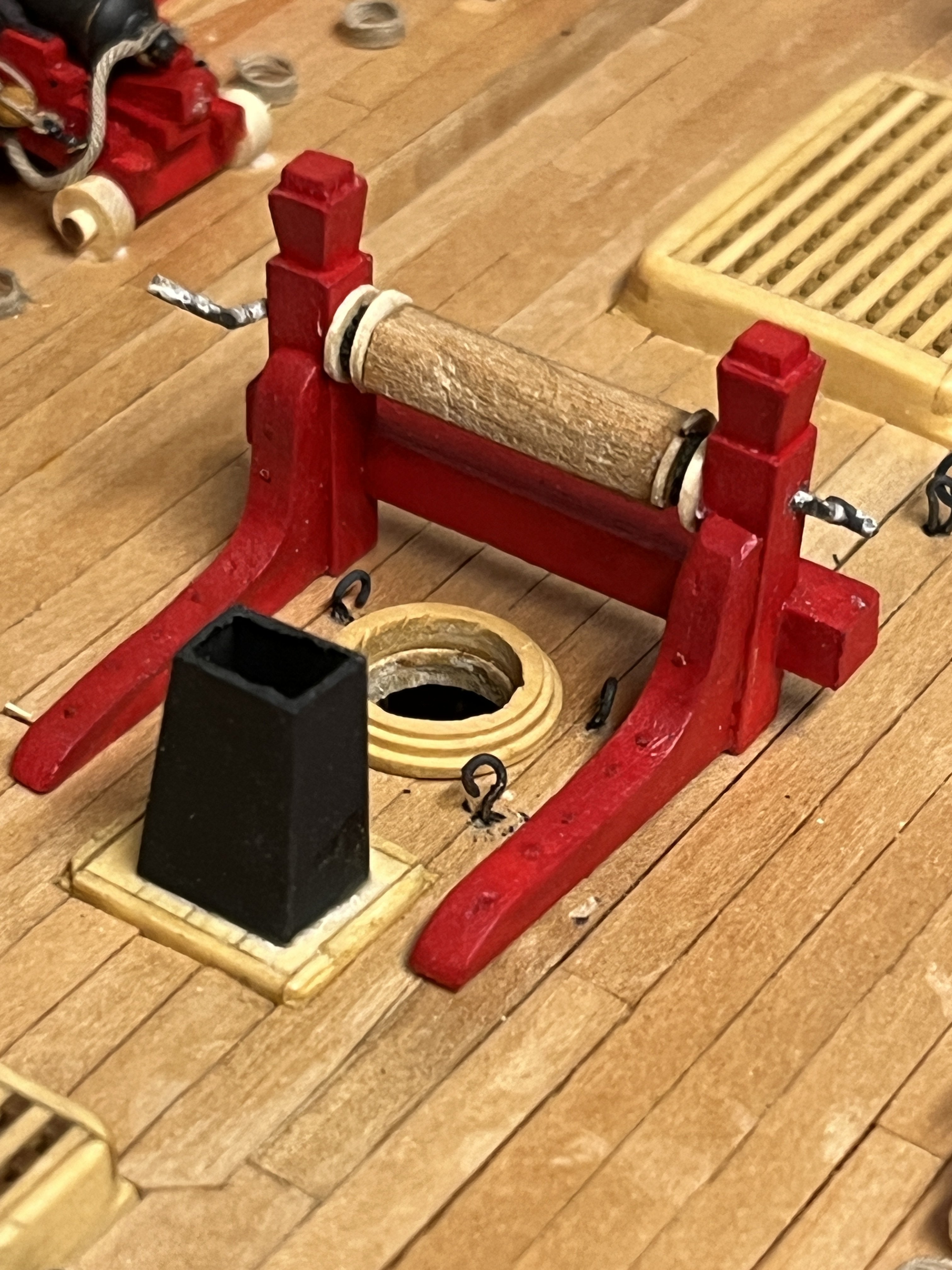
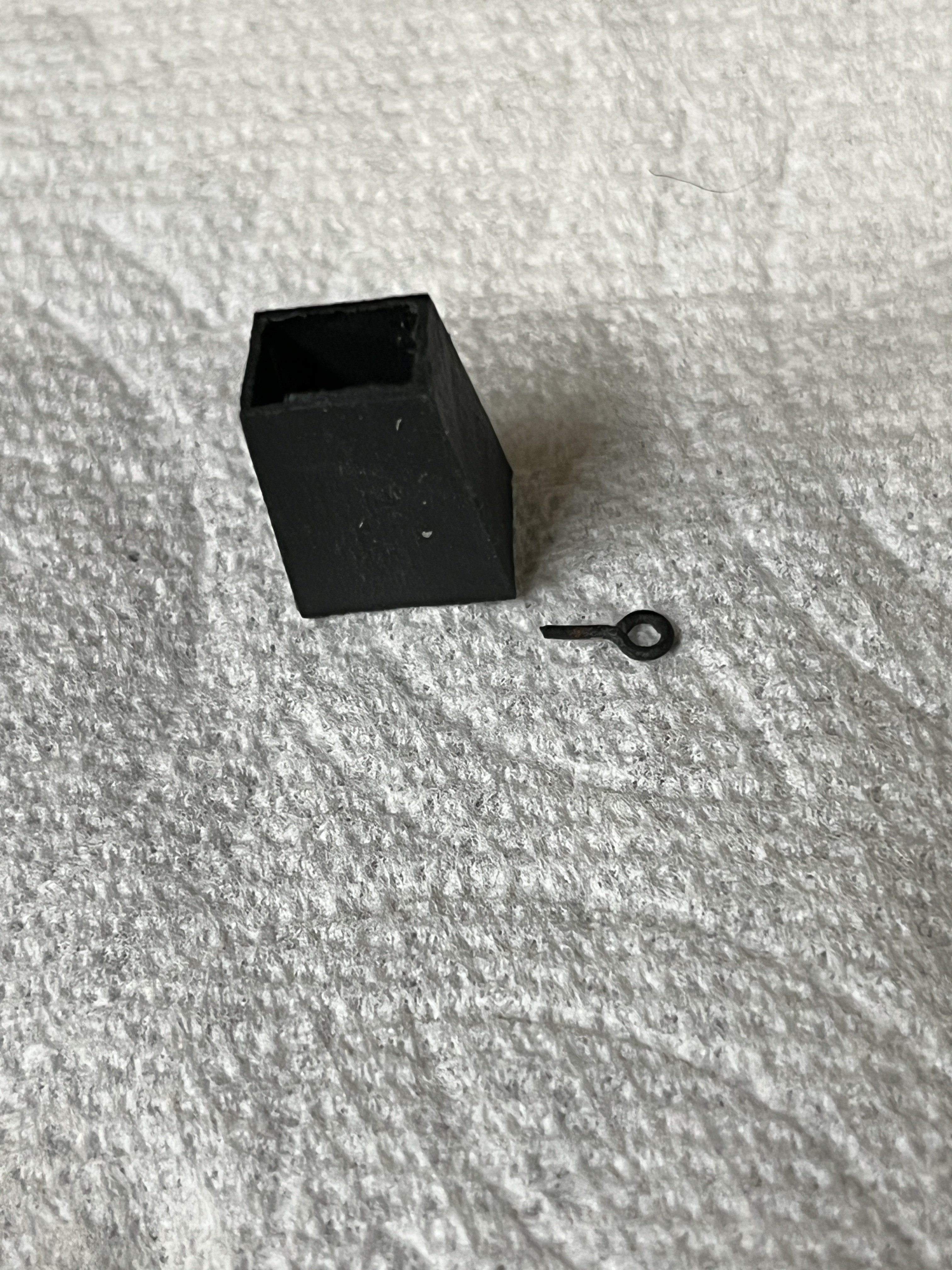
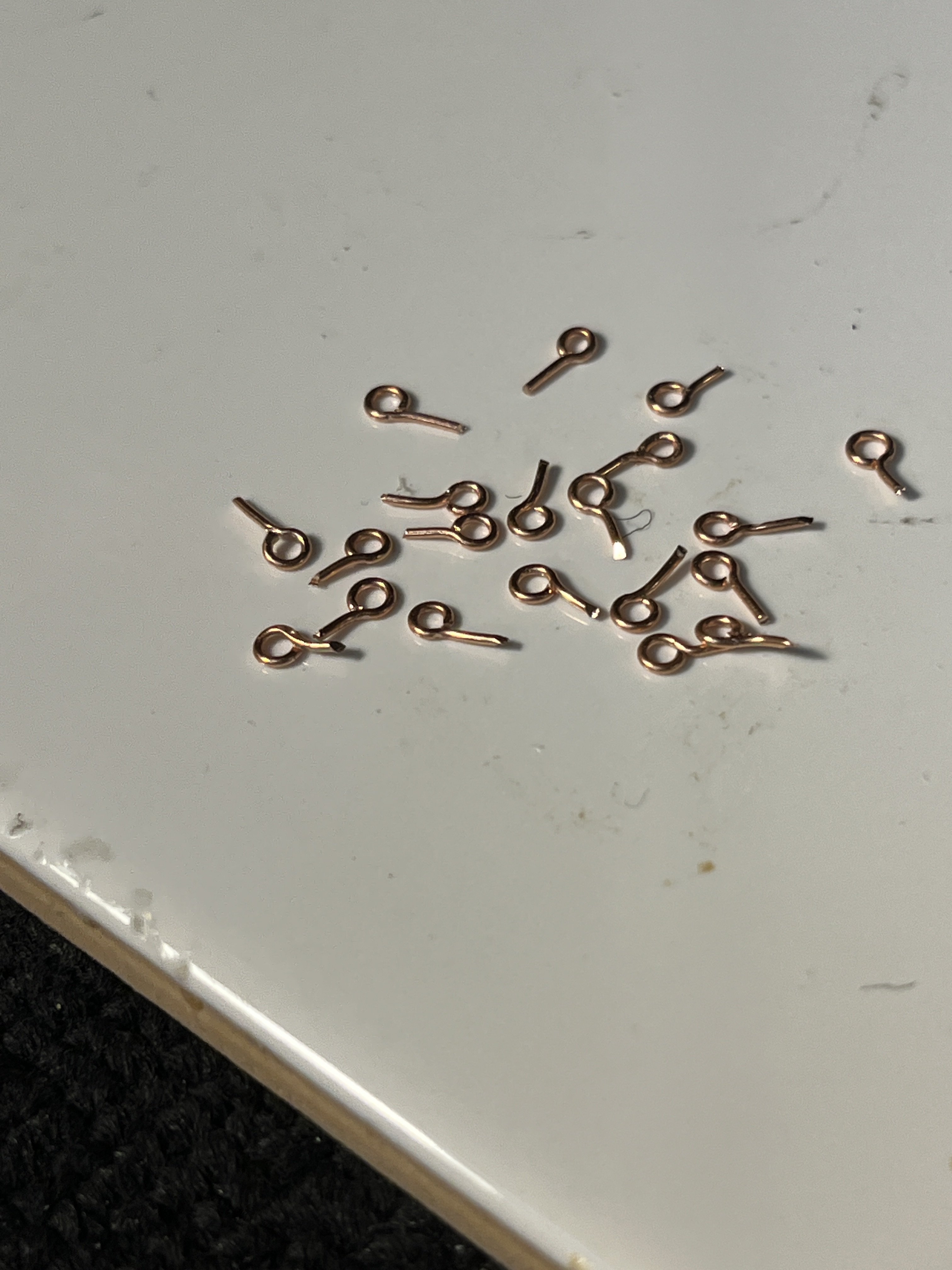
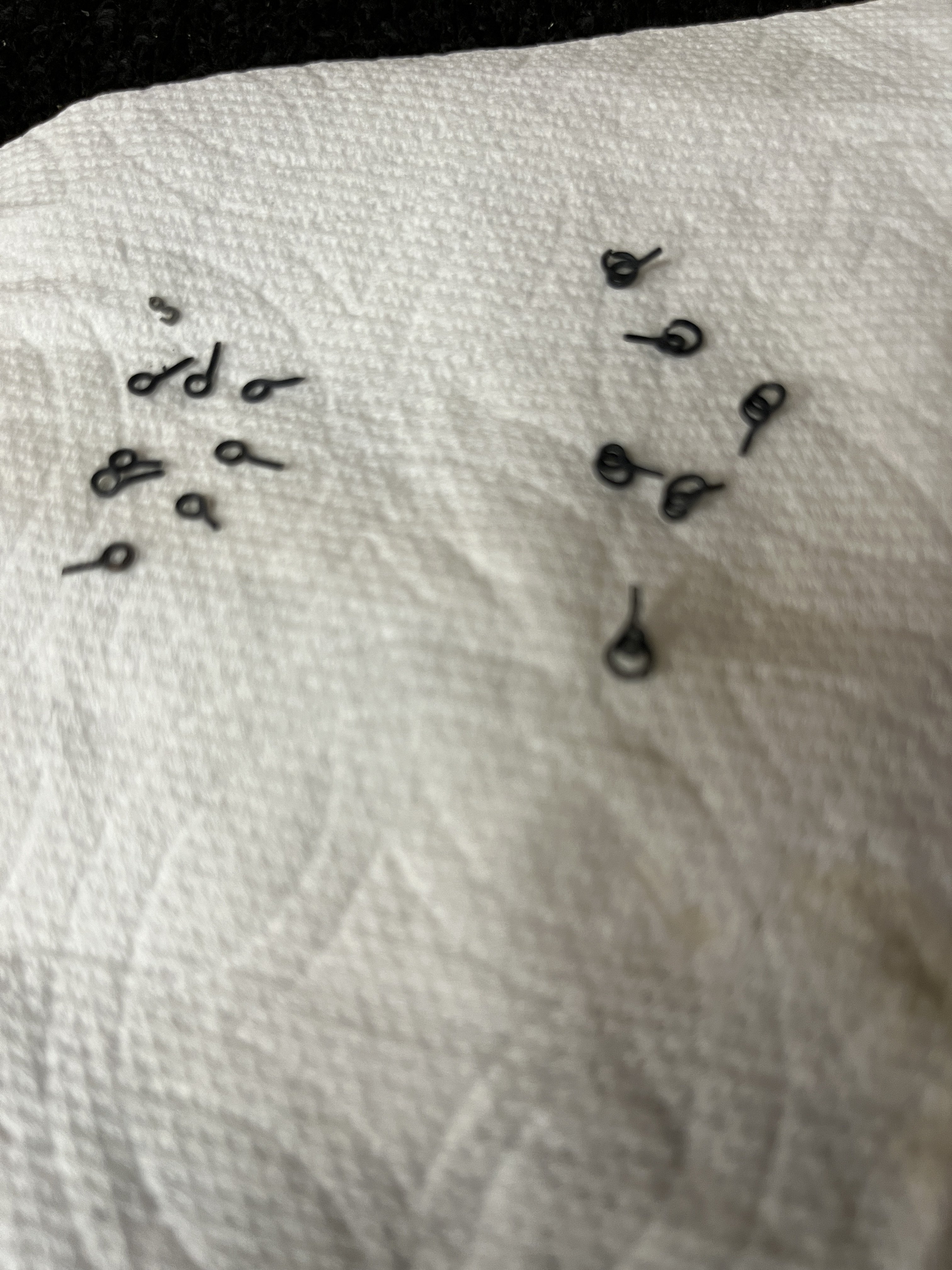
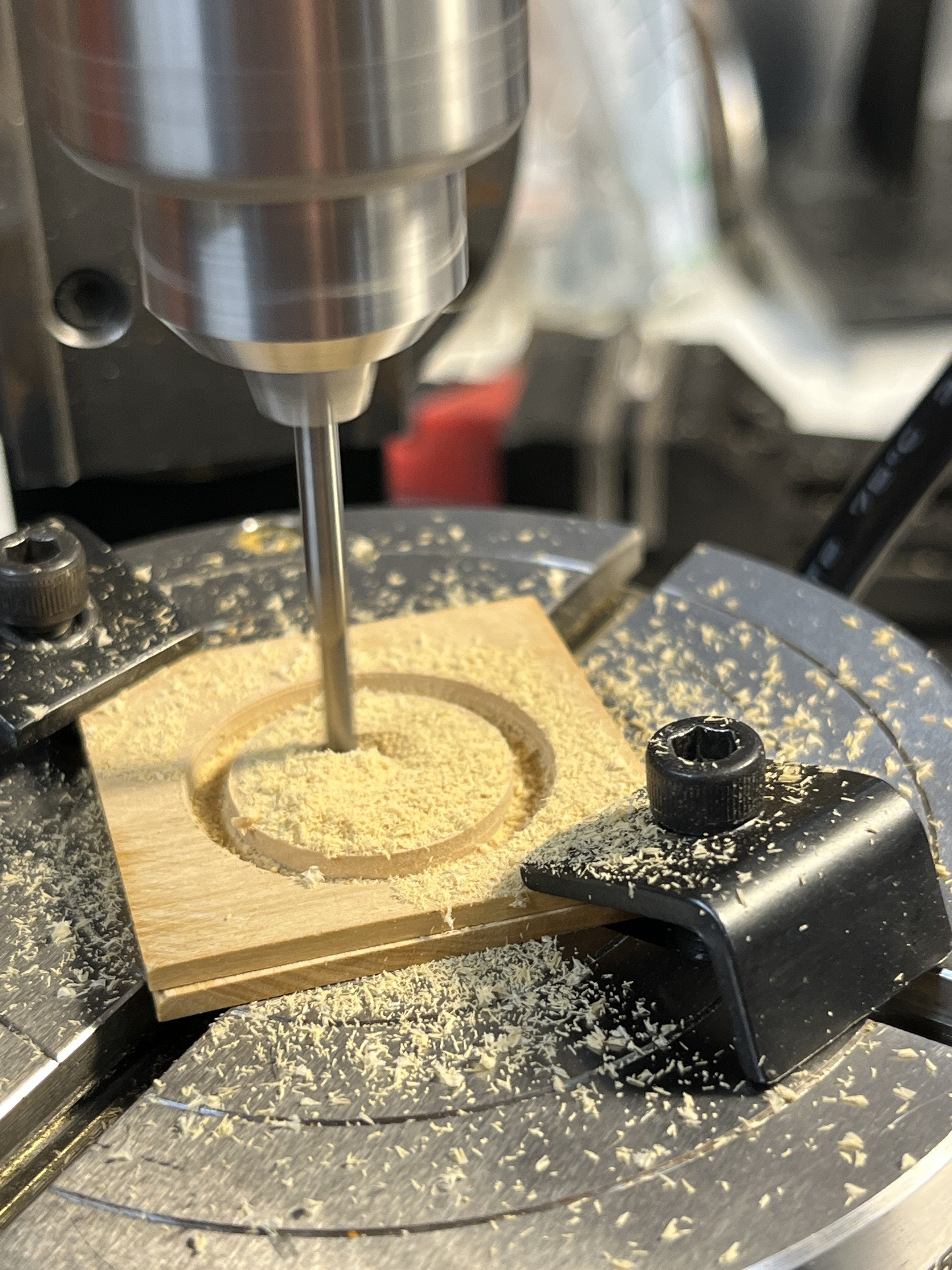
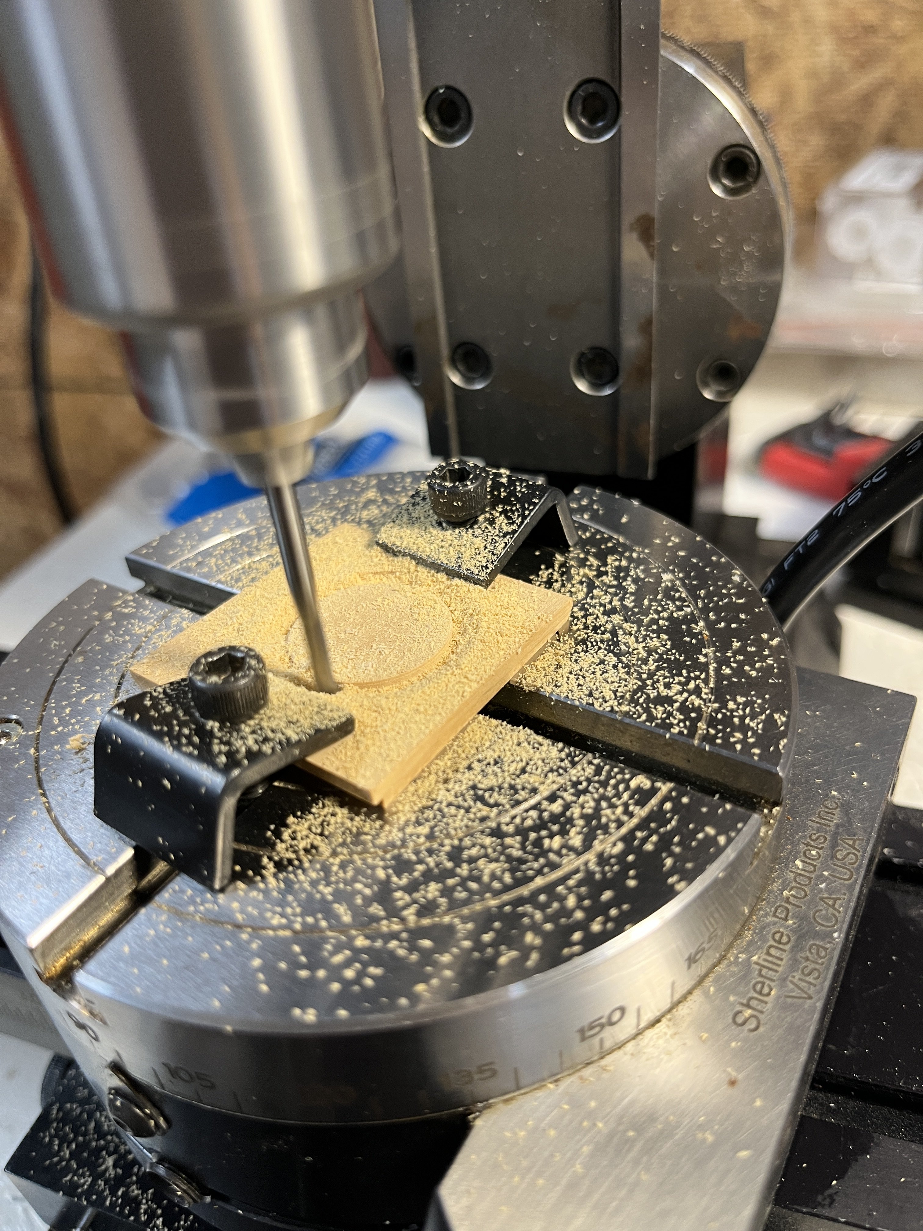
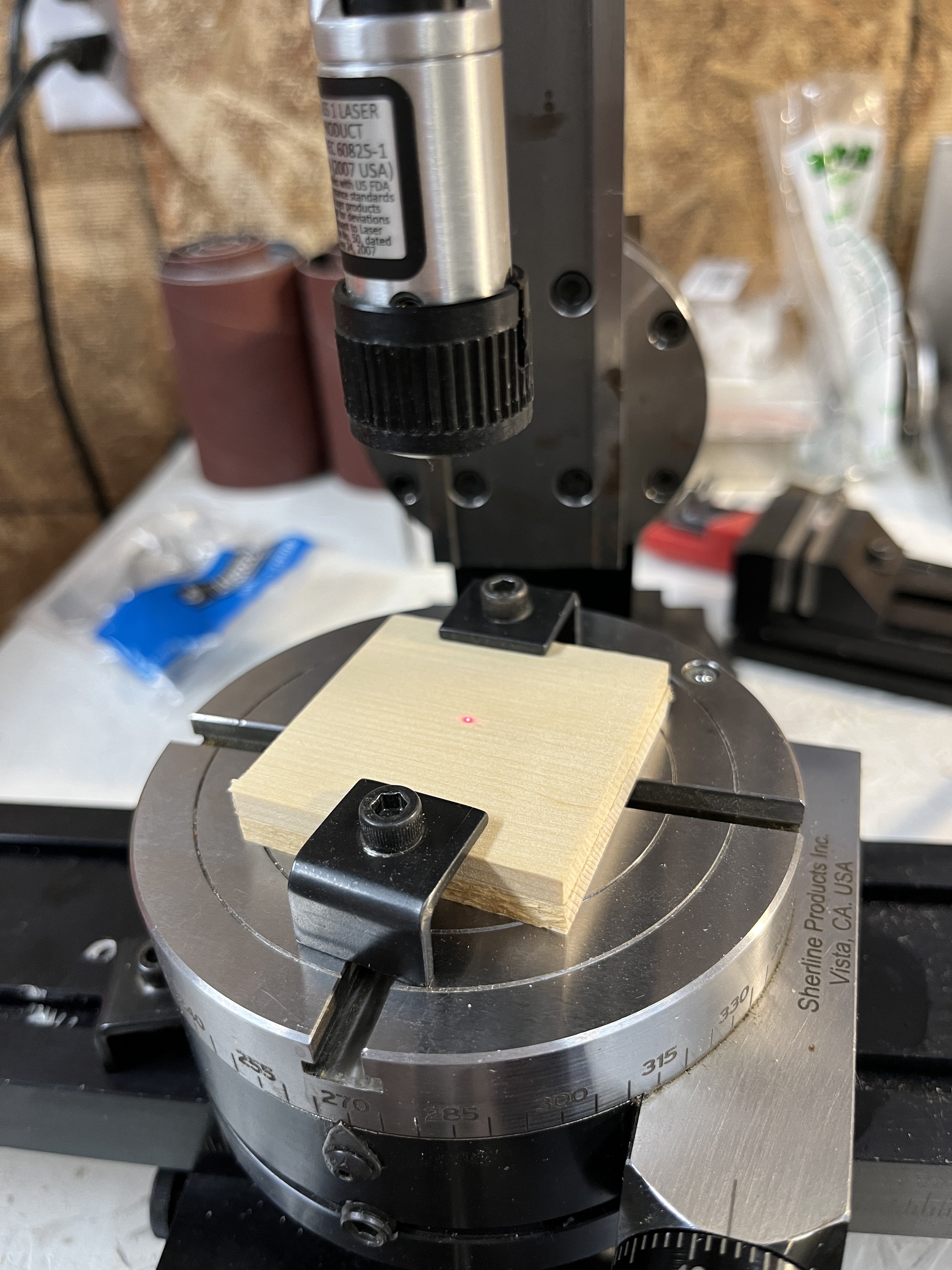
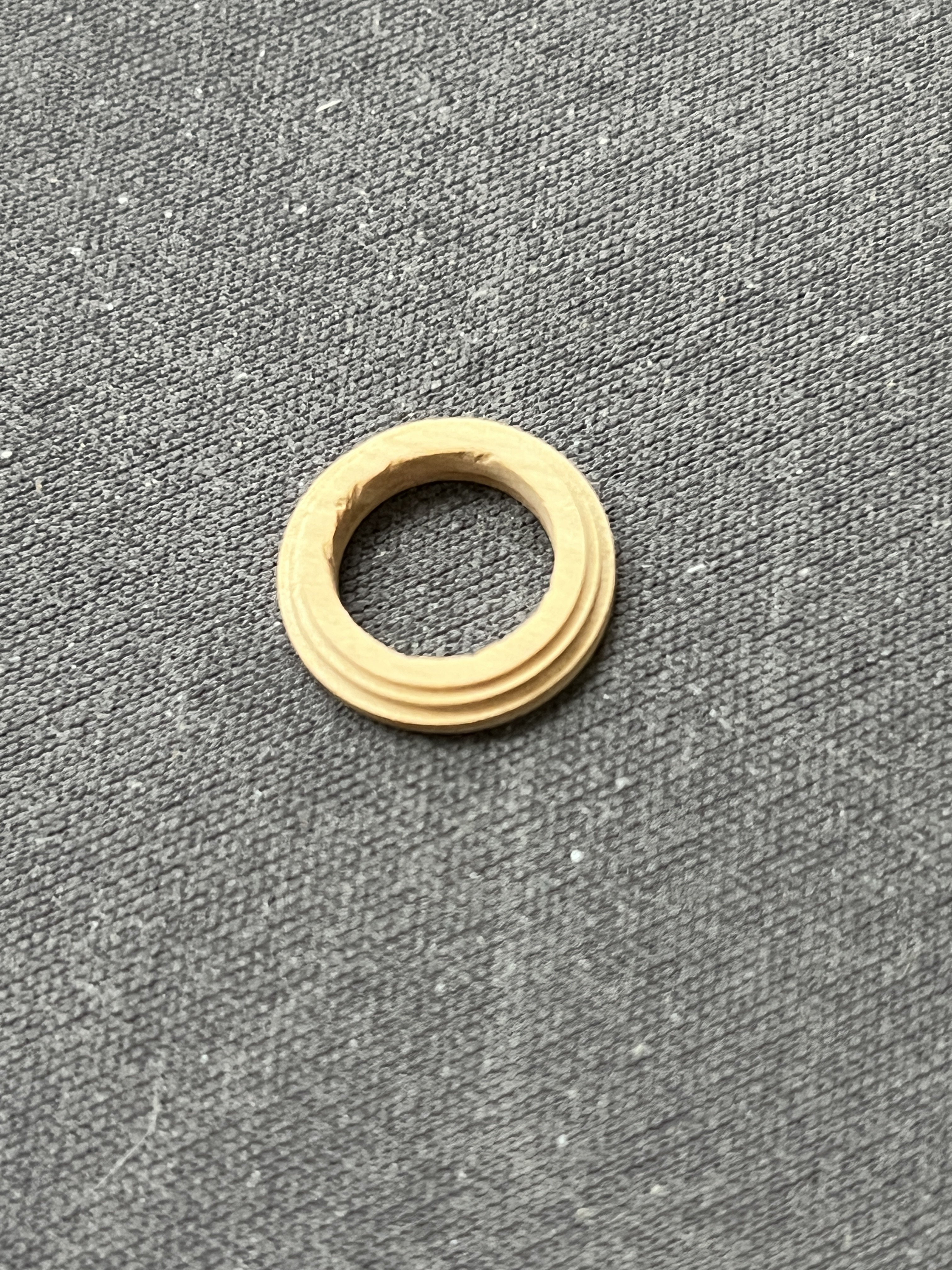
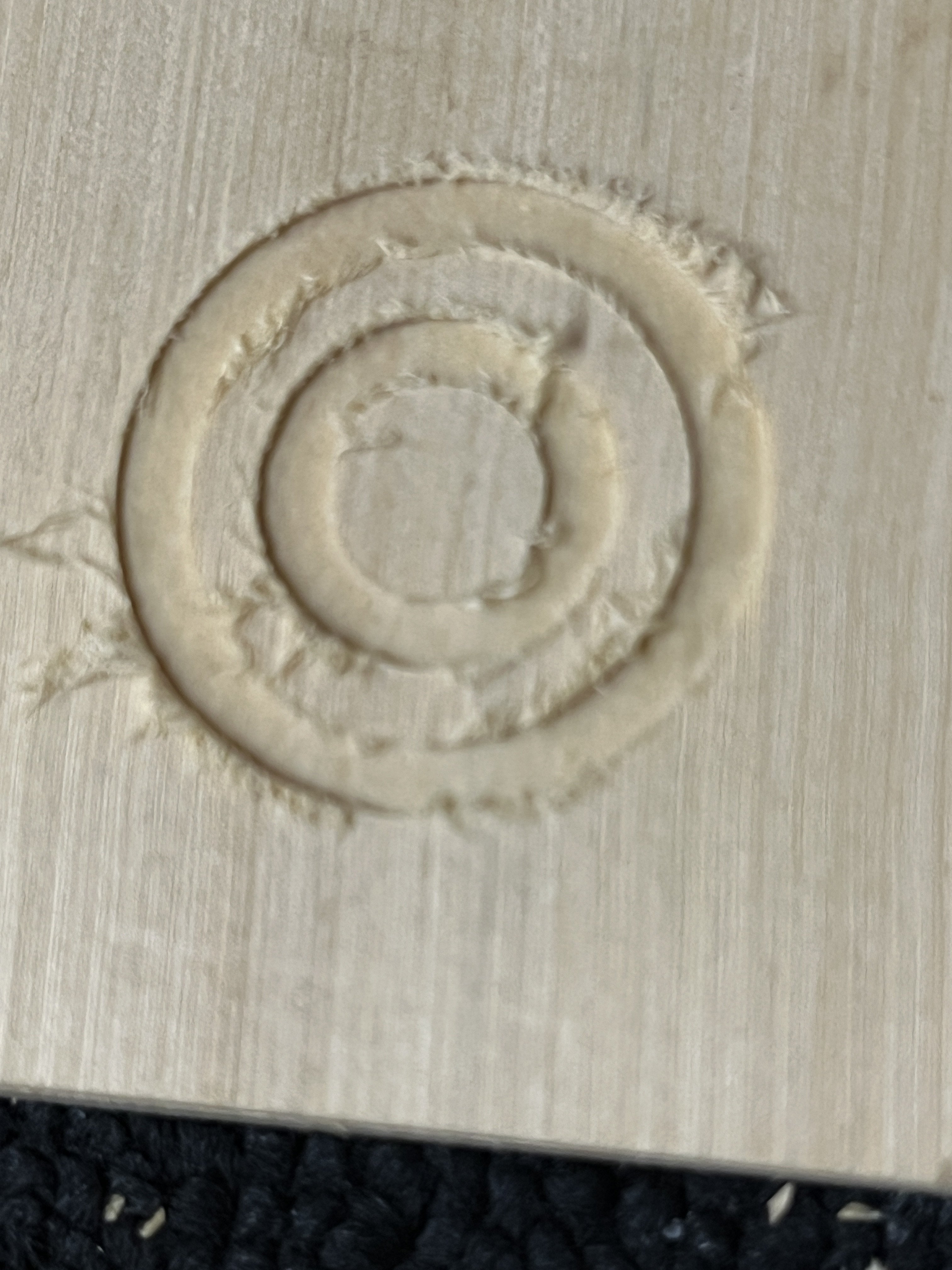
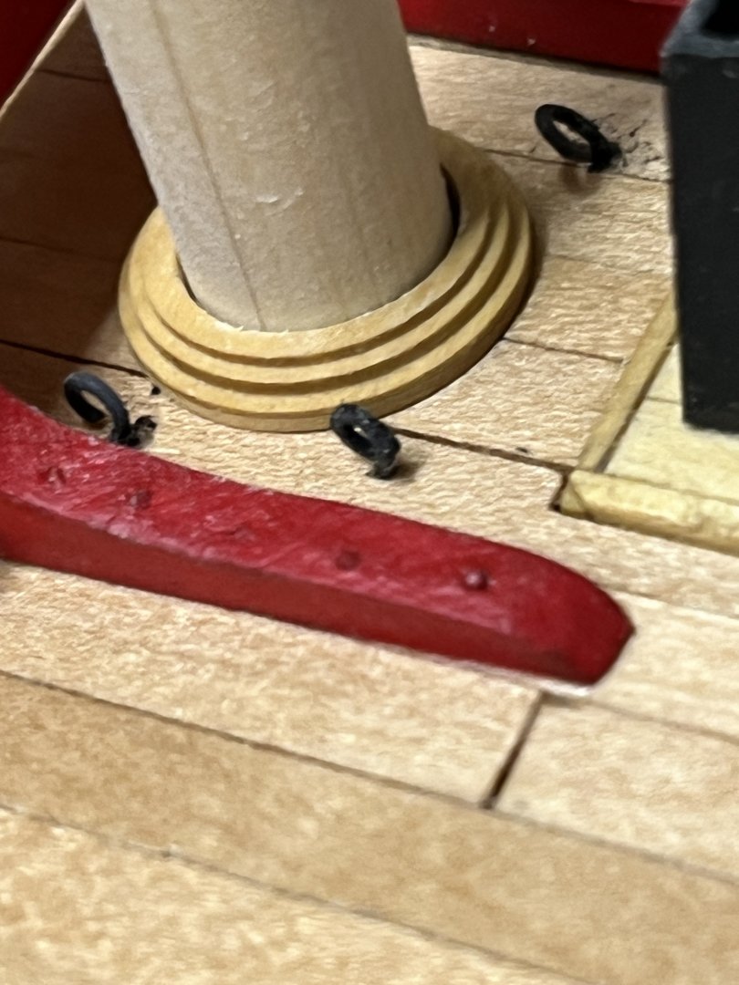
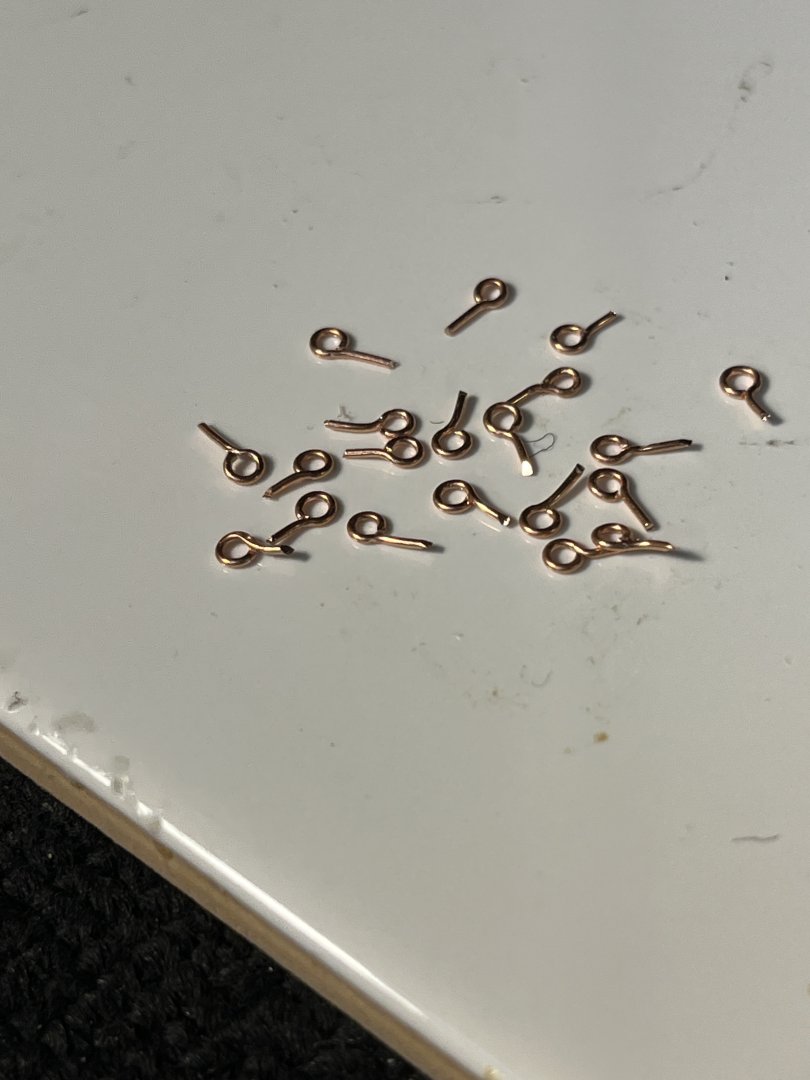
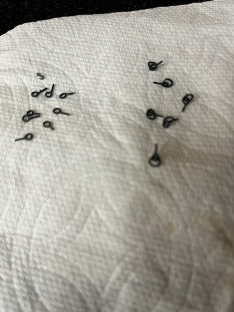
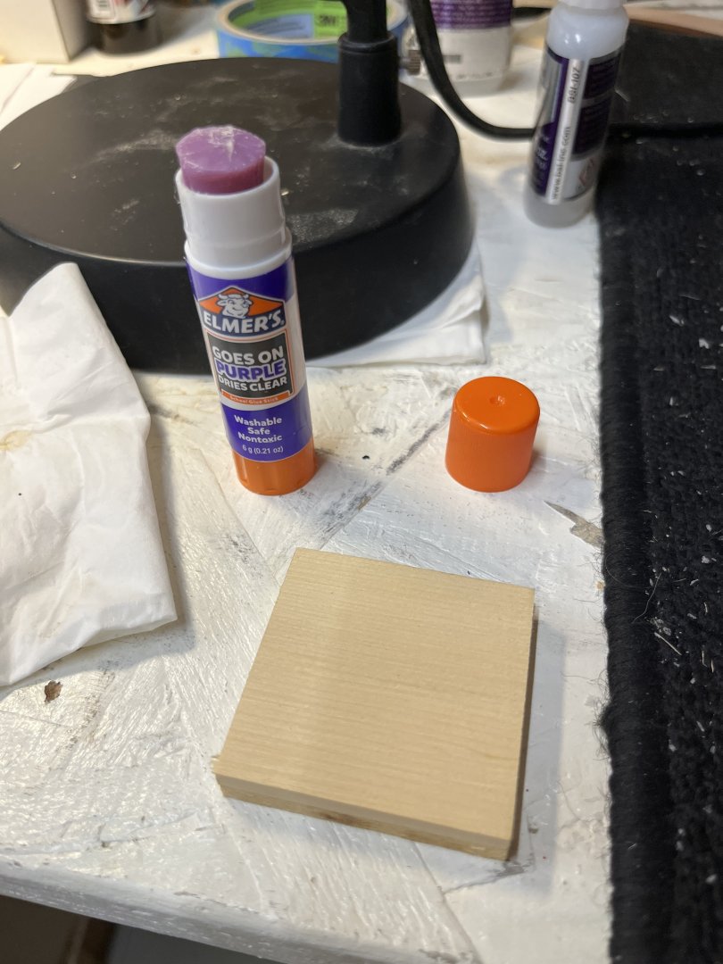
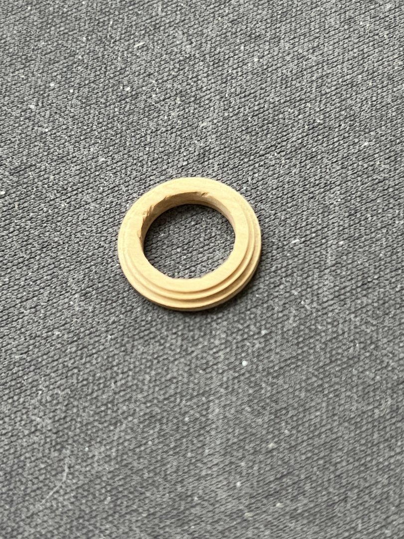
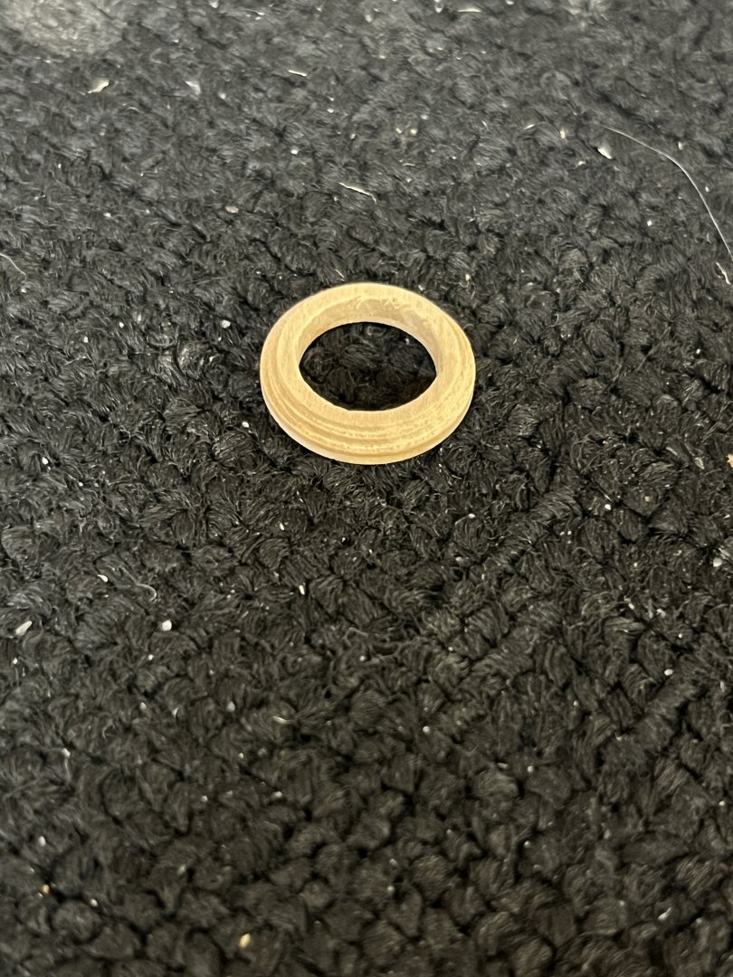
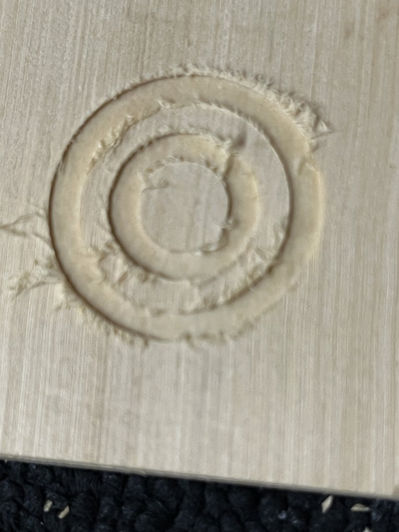
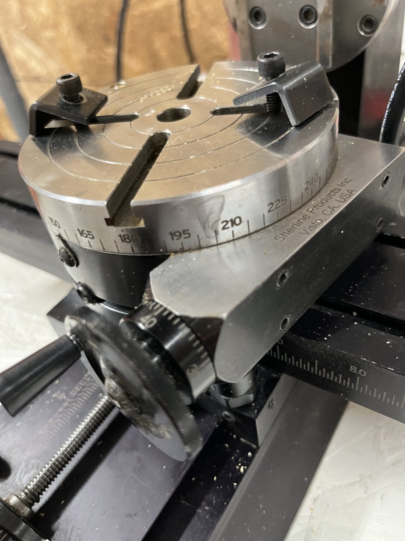
Good Morning on July 6 and it's been too long between working on the model and posts. I spent some time making the deck eyebolts using the same technique as before by silver soldering the rings closed. This afternoon will be spent plating the parts black and ready to put on deck. I had forgotten that in my notes the eyebolts had been etched and cleaned in the ultrasonic so that they were ready to plate. Sitting on towel to dry After looking at others methods to make the mast coat I decided to use my mill with the rotating table. My first attempt using Alaskan Blue Spruce was not successful as the softness of the wood just left fuzzy edges so out came boxwood. Using my rotating table mounted to the mill to cut the circles for the coat. I2mm boxwood wa used for the coat. The boxwood was not thick enough so I glued two pieces together with opposite grains for added strength. Using school glue as it makes a strong joint and can be easily remove with water. Mounted the wood was a simple process as you would on all mill beds. A 3mm end cutter was used to cut the circles. The hardest part was calculating the radii as 3mm is .118 so much drawing and calculating making sure I had the correct inside and outside diameter. Getting steps on the outside was simple after cutting down the depth and raise the cutter and with a smaller diameter. These are the finished mast coats, I made two for emergencies, prior to wipe on poly The little chips on the top will not be seen one I sand the mast coat to the correct height. Using my rotating table was a wonderful learning experience and I have many ideas of how to use the great tool in the future.


-
Martindale blades for Byrnes saw...
niwotwill replied to CPDDET's topic in Modeling tools and Workshop Equipment
Great information about how and where you got your bladed. With the two names listed I was unable to find how to contact them, could you explain how you were able to contact them? How many blades did you have to order? Thanks -
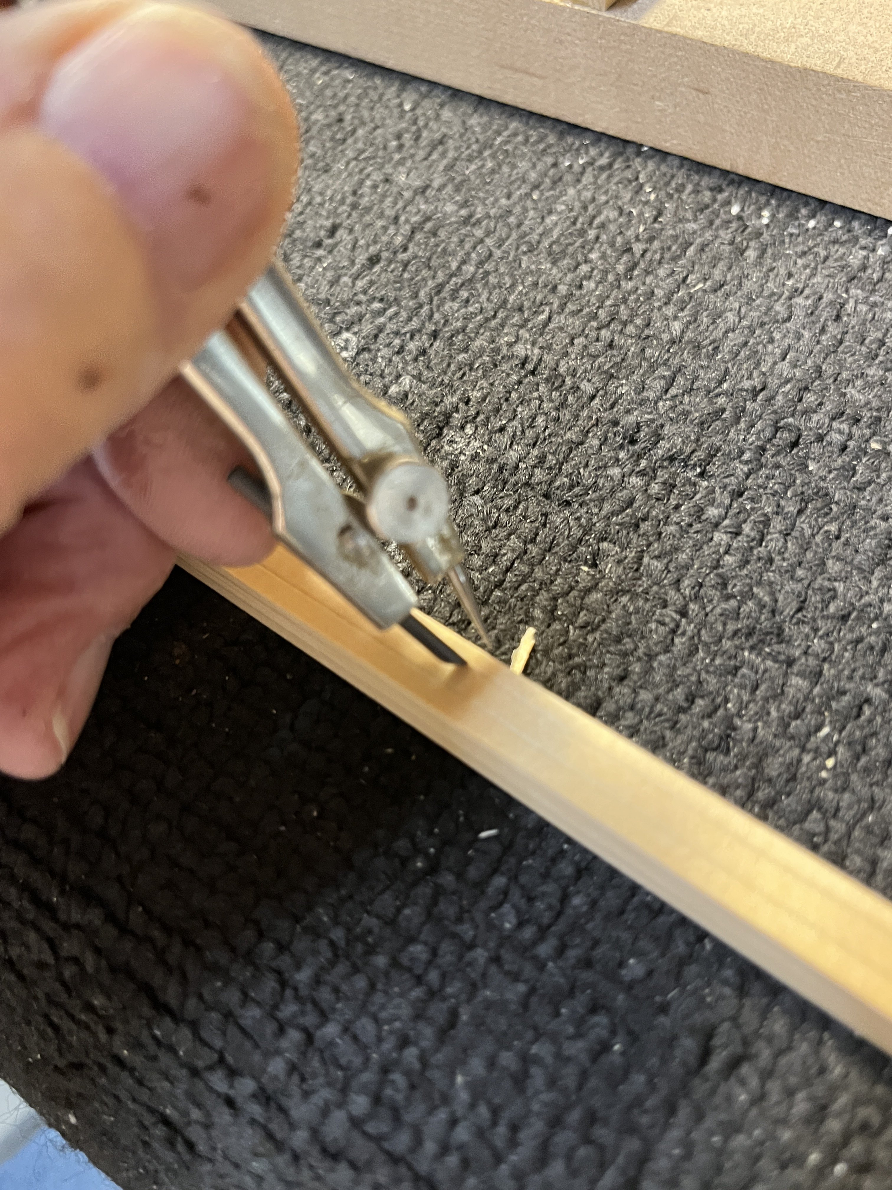
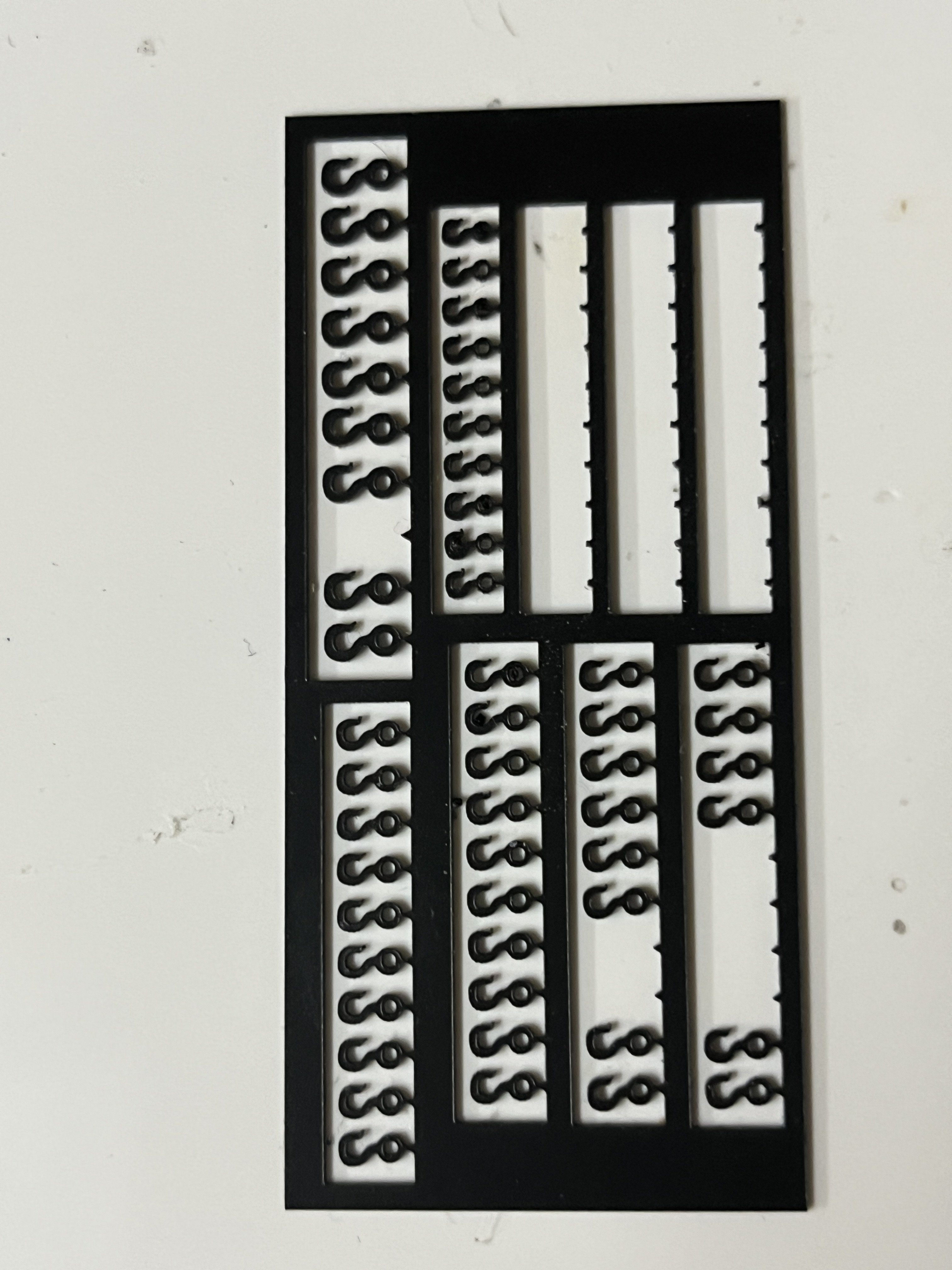
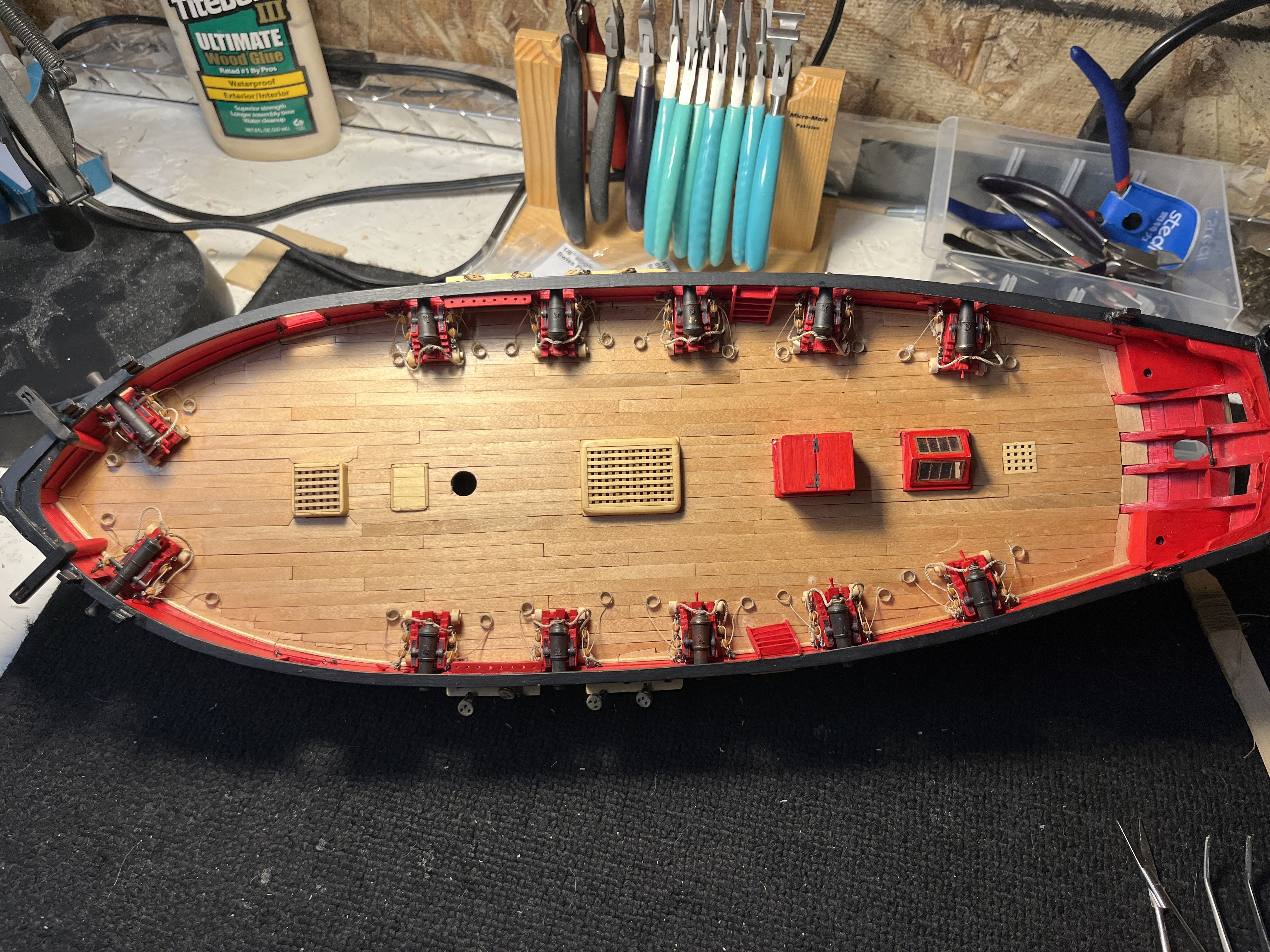
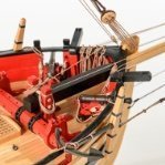
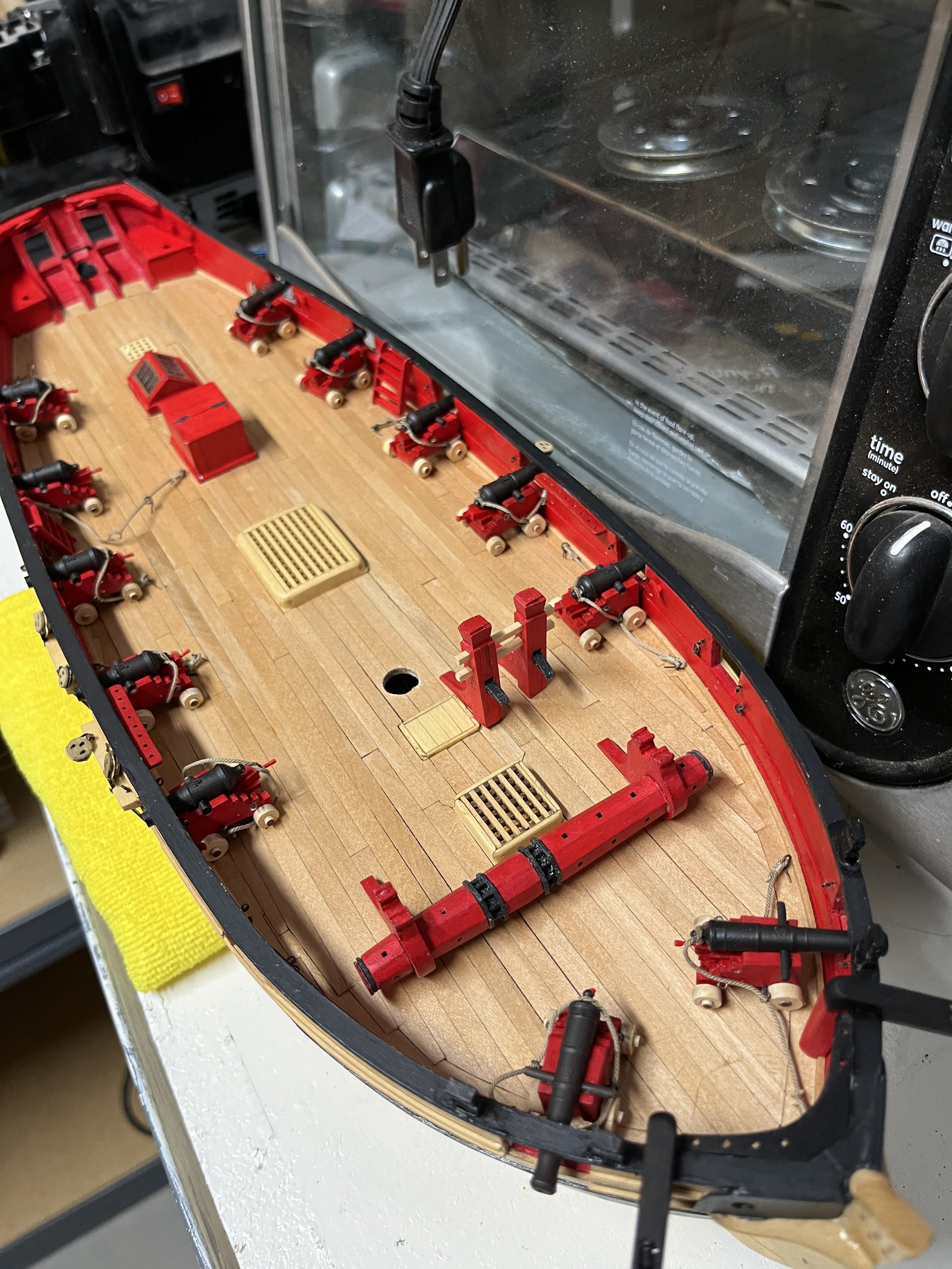
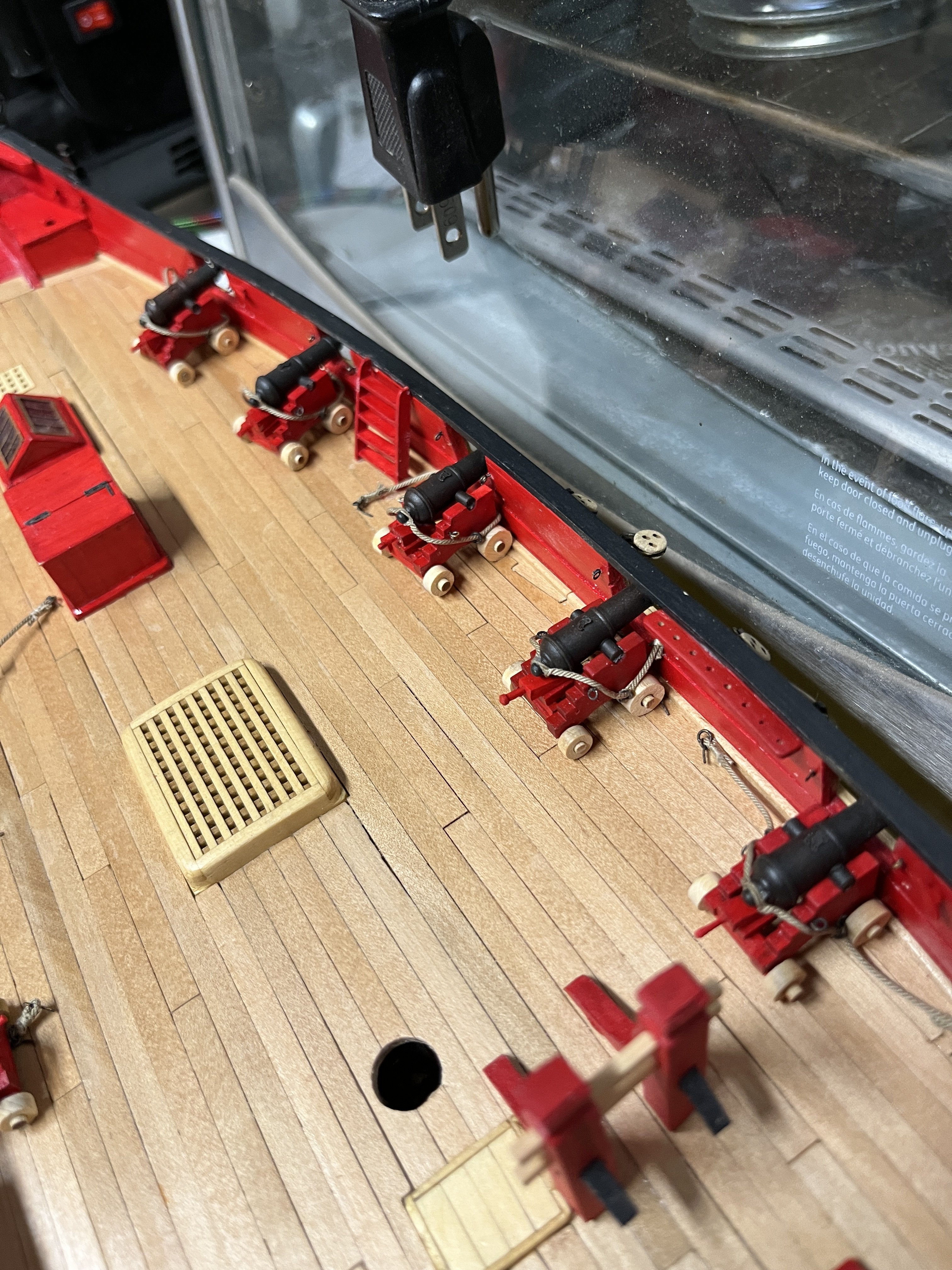
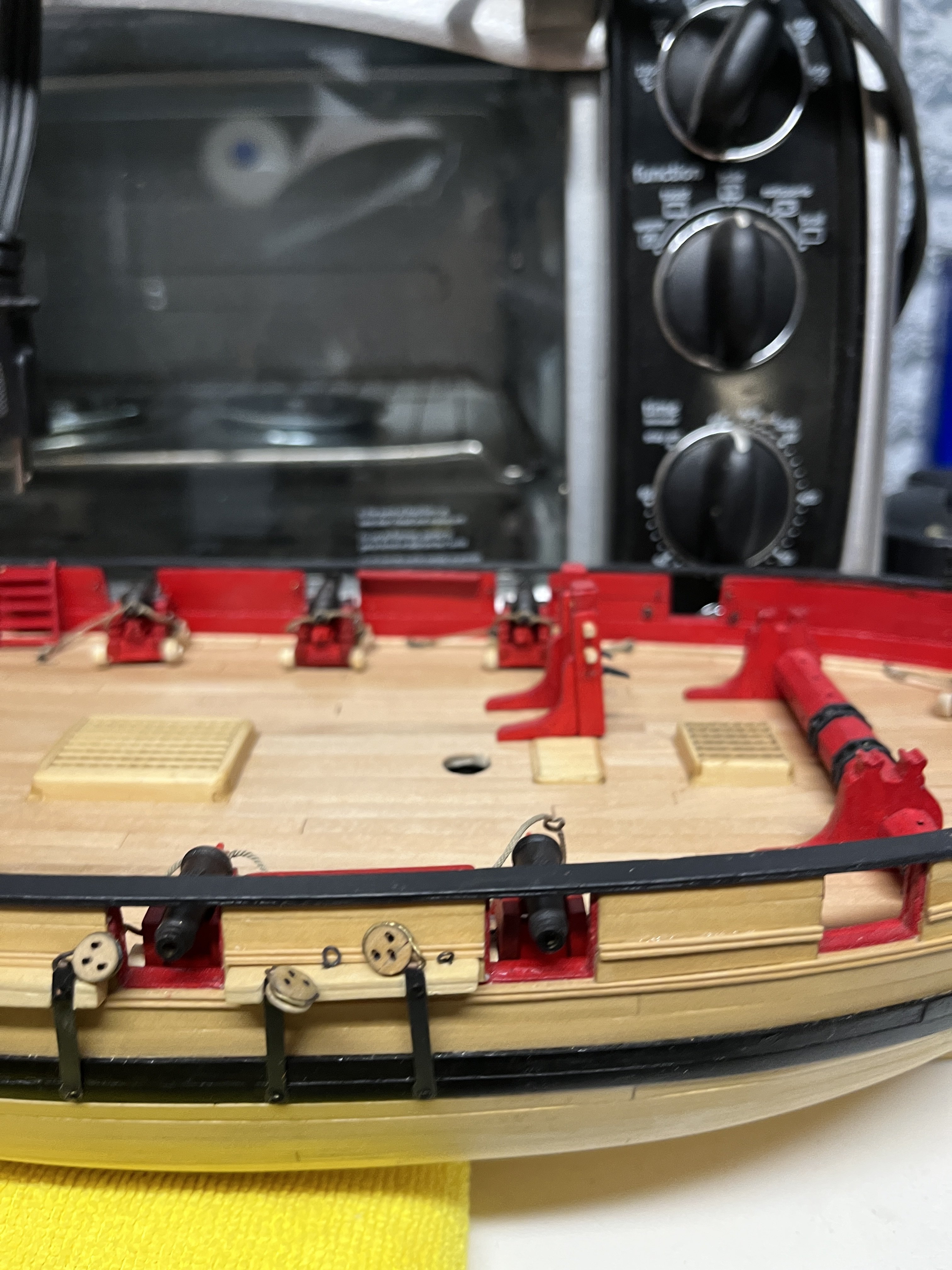
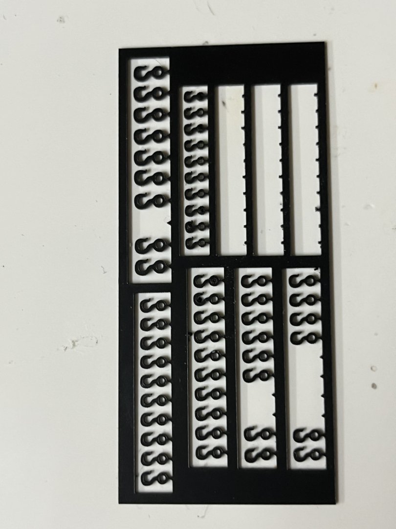
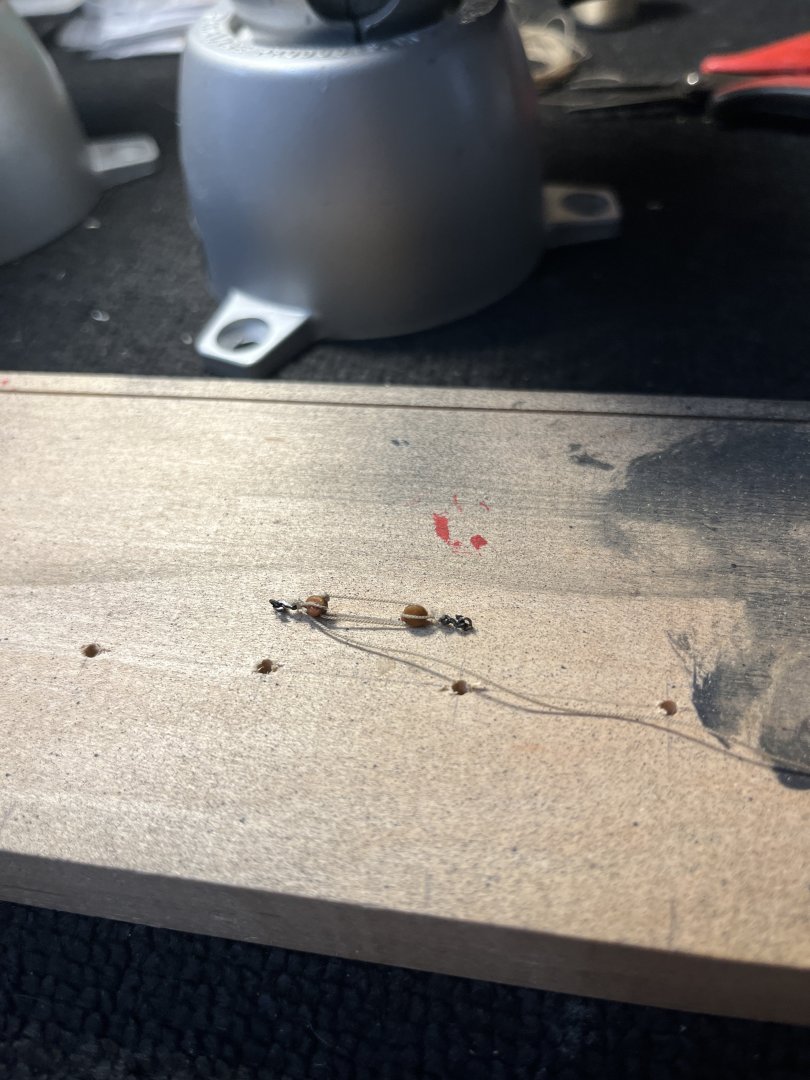
With the breech lines completed and the carriages glued to the deck it is now time to start the tackle. I used the 3d printed hooks from Syren Model Ship Company for the block hooks. The sheet of hooks had 3 sizes and I used the smallest which gave the visual proporations of hook to block. The 3d sheet gave the smallest hooks a visual thickness to the hook. A simple jig was made from a piece of wood that had been used for many purposes. The holes last used to paint the cannons with the jig and tackle visible the groove along the top was used to shape planks on plank on frame kits. The slot was quite unique to hold the plank while being planned to shape. This slot was make the thickness of the present blank. With the tackle made now it was time to rig the cannons. Again when a step seemed easy it proved not to be easy. Getting into the bulwark rings was very difficult requiring many sized and shape tweezers. The 3d hooks were fairly fragile and required the remake of several hook/blocks. Now with chapter 10 complete

-
Hello Glen
It's been awhile since I've checked in and need help. Mast coat is my next step and reading logs you mentioned @DelF as one to look at for help in you post #429 page 15. Could you forward the post where @DelF described his method?
Many thanks and your posts are amazing making great late night reading.
Willi
-
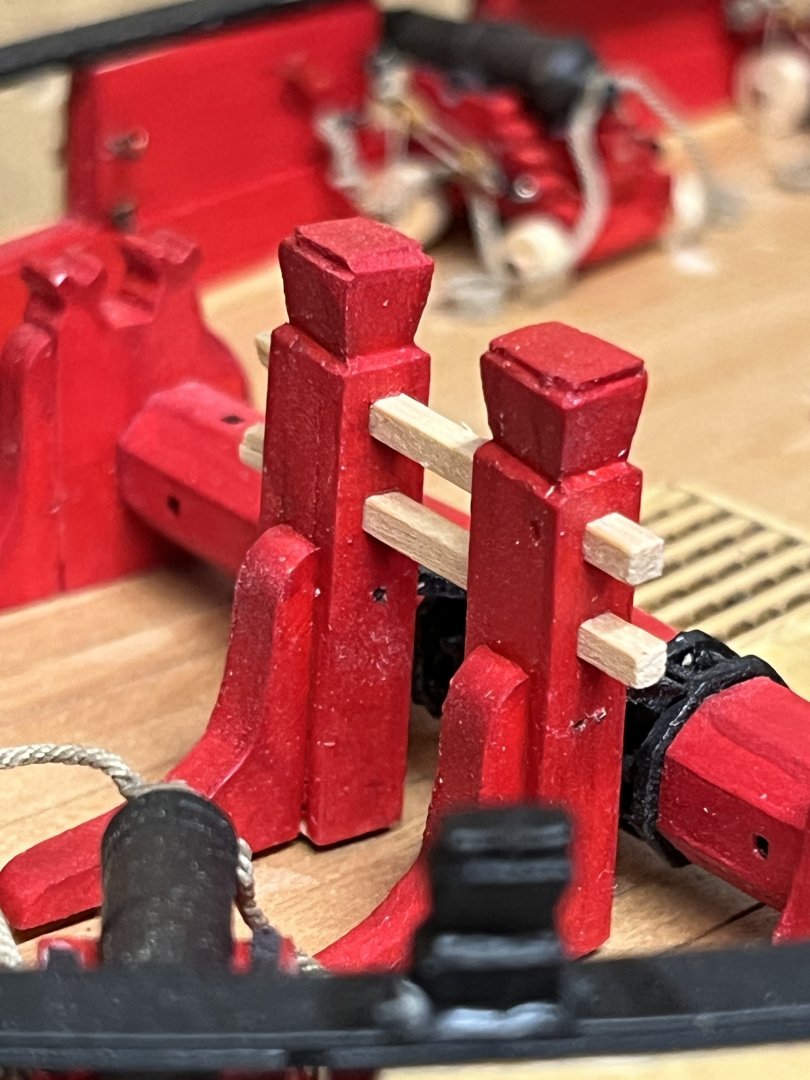
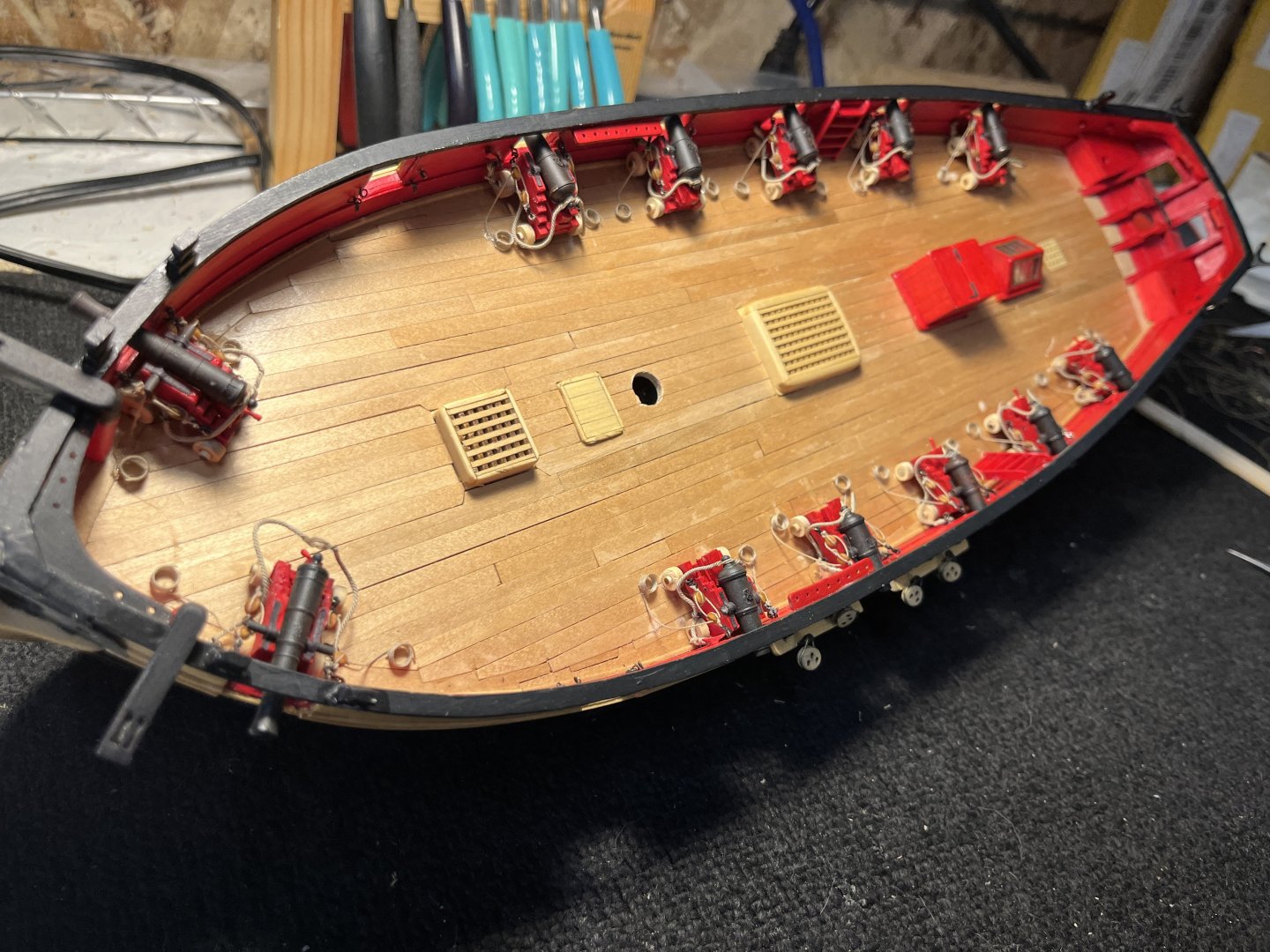
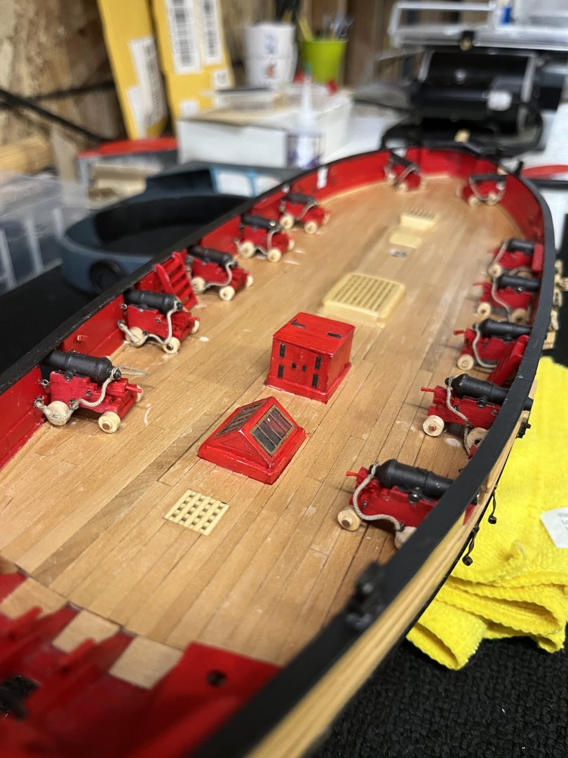
After much thought over the last few days I decided to leave the wheels in their natural color. I finally glued the carriages in positioGn on the deck and attached the breech lines to the bulwark. Getting the breech lines to hang/droop in a relaxed position is going to be a work in progress but they are starting. The next thing is to strop the blocks for the gun tackles.

-
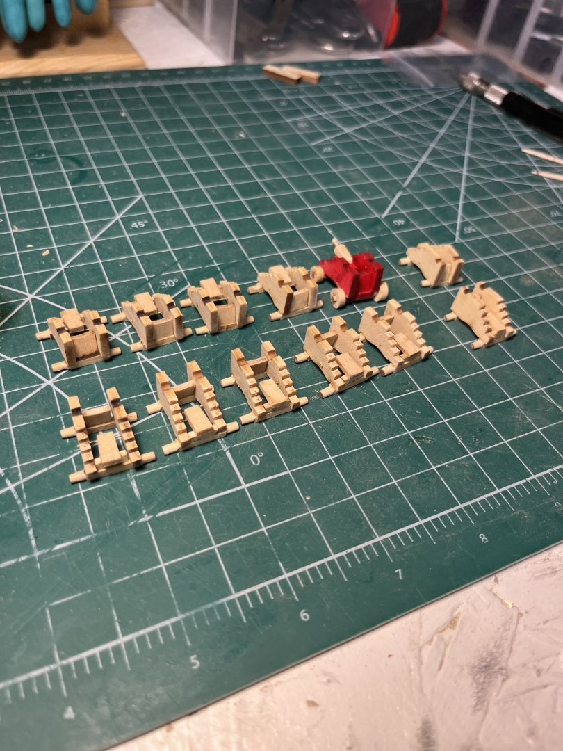
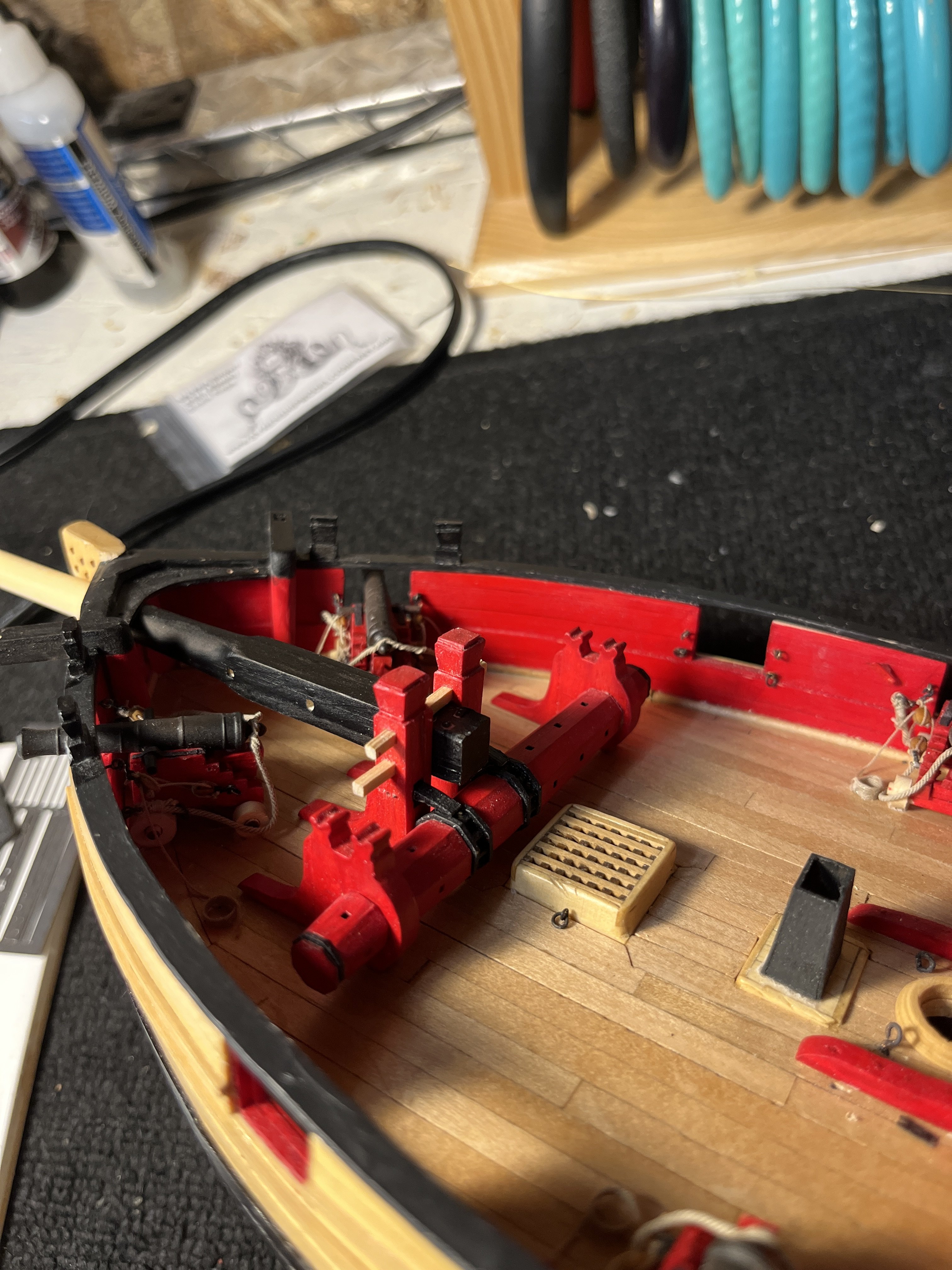
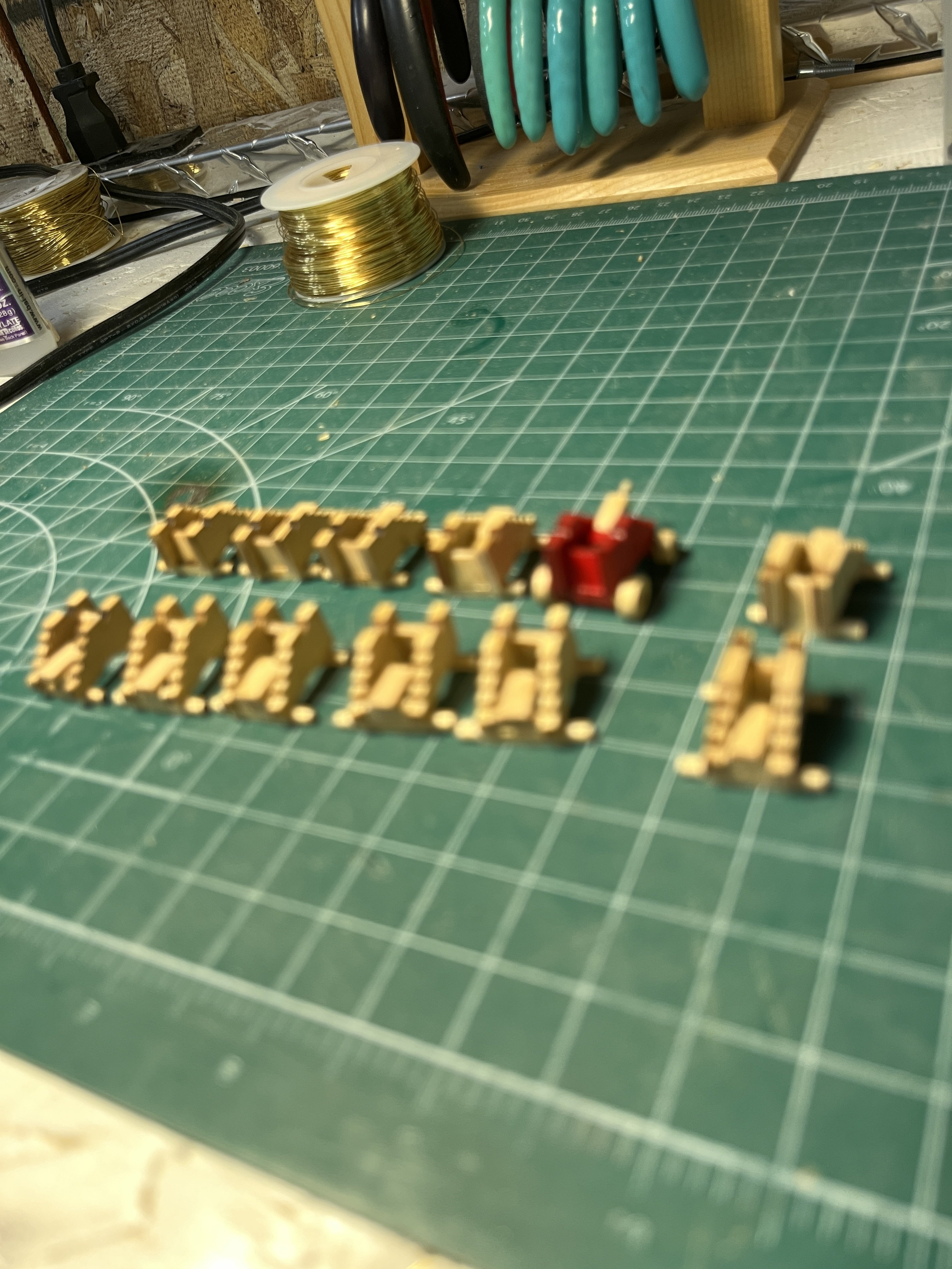
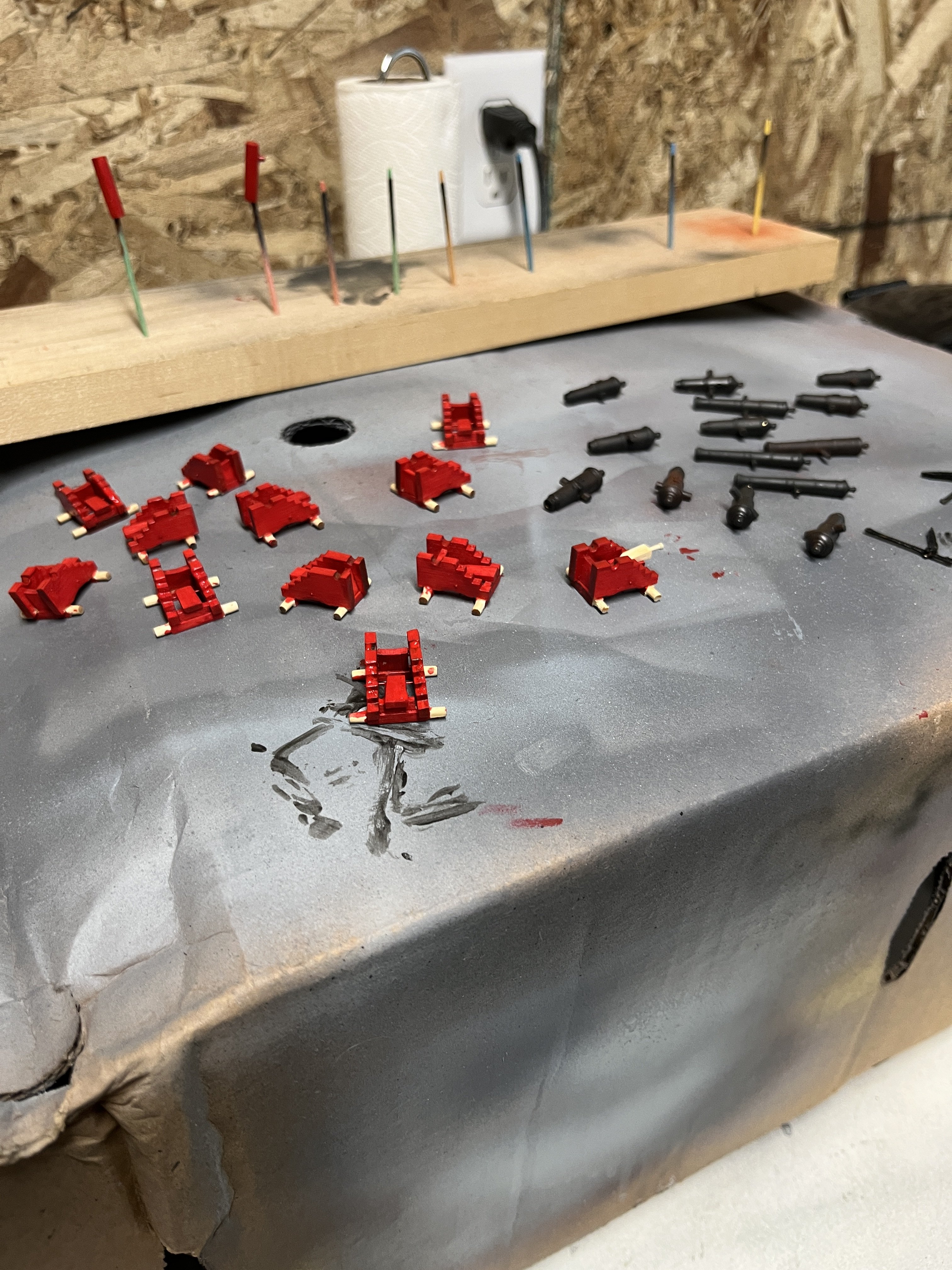
Had a slow period over the holidays and not much to show. I made the elm pumps and all the carriages along with the breech lines. carriages assembled ready for paint carriages and gun barrels painted elm pumps completed and I use 1/16" brass tubing for the discharge tubes leaving an exit hole although nobody will see the hole but I know its there. got the breech lines attached to the carriages and just placed the armanent for my pleasure I still have to make the attachment caps to sit atop the carriages. Also need to decide if the wheels should be painted and I might try staining a scrap piece of AYC a medium dark to dim the wheel brirness. Tomorrow I'll start the harnesses and glue the guns in place.