


shipmodel
-
Posts
936 -
Joined
-
Last visited
Reputation Activity
-

 shipmodel got a reaction from mtaylor in SS Kaiser Wilhelm der Grosse 1897 by Mirabell61 - FINISHED - scale 1:144 - POF - first German four stacker of the Norddeutscher Lloyd line
Hi Nils -
I thought that I had read through this log, but somehow I missed it. Seriously good work, my friend!
Spent an enjoyable two hours with it and found several ideas and techniques that will work their way into my own projects. It was fascinating to see how the techniques that we use are both similar and different because of the scales that we are working in.
I am now hooked into the log for instant updates.
Dan
-
 shipmodel got a reaction from popeye the sailor in SS Andrea Doria 1952 by shipmodel - FINISHED - 1/16" scale
Build log 7 – more bow details, boat deck
Thank you Greg and Nils. I'm not sure that the model merits three "wows" yet, but I will keep trying.
I continued the build by turning to some of the detail work that had been put off till more of the coarse work of building up the decks was done. These included the external anchor and the ship’s name. The plans and photos show that the anchor is set in a square depression with rounded corners that is shallowest at the upper edge and deeper at the bottom. The color separation line crosses it.
I made up a quick template from a plastic strip and scribed the tilted outline on both sides of the hull. With a flat-bottomed carving bit and a light touch I carefully removed plastic and wood until I had the depression that I wanted. The bottom was smoothed and a hole was drilled to take the mounting post of the anchor fitting. The depression was painted in black and white to match the hull, then the anchor and hawse pipe fitting was pinned and glued in place.
The name was another custom decal created in my computer. Photos of the ship show that the letters were raised brass, which I could not duplicate, but Photoshop let me select a gold tone for the letters with a narrow black shadow effect that makes them stand out.
For the draft marks at the waterline I located a decal set from Europe in 1:200 scale using the correct Roman numerals. These were applied vertically port and starboard near the bow and at the stern up the rudder post. Since the carrier was clear no edge painting was needed.
The Plimsol Line marking could not be sourced, so it was custom made. I researched a number of sites for the design and learned that there is different lettering depending on the country of registry of the ship. The “R” and “I” indicate an Italian ship. Because the symbols are white, and I don’t have a Cartograph printer, I had to use white decal film, so the black and red colors were also printed. It took a number of experiments to get the right shades. The best one was printed out, set in place, and the cut white edges hidden and feathered with paint.
On the bow working deck I made up the anchor machinery. I never could find a clear photo of these fittings on the Doria, but I did find one taken of them on a contemporary Italian Line ship, so I used those as the patterns. First the hawse pipe openings were located and drilled out about half an inch deep. The pipes were painted flat black before metal hawse lips were painted and installed.
The anchor chains run through chain brakes, then aft along a chute with raised sides, then around the anchor winch and down an elbow fitting to the chain locker below. A combination of several pieces of various metal fittings and scratch-made plastic elements, and an overall coat of grey paint, were needed to make it look like the photos. After pinning and gluing the winches down a set of margin planks were added to make them look built into the deck.
The spare stockless anchor rests against the forward wall of the deck house and is secured by a narrow strap.
The next deck up was the boat deck which turned out to have a surprise for me. When I stacked the rough decks and deckhouses to see how they fit, something didn’t look right. It took me about a week to realize that it was the boat deck. I had assumed that all of the decks were the same height, but the plans showed that the boat deck was some 2 feet taller. This then required a quick scramble to add another 1/8” sheet of basswood to the deckhouse. Lots of clamps were used to get a tight fit between the pieces.
All of the edges were shaped to final lines with a benchtop 6” sanding disc, which also insured that they were vertical. Notches were cut for doorways as indicated on the plans. These entryways now made sense, because they now had the room for short stairways to the doors leading to a raised floor.
The sheathing is 0.020” styrene sheet which is easily cut with a knife and straightedge. I find that cutting all the way through leaves a burr along one edge, so I scribe the line about halfway through and then bend and snap it the rest of the way. Very little cleanup is needed with a medium grit sanding block.
The sheathing is glued to the wood with medium thickness cyano. I lay a bead of it direct from the bottle onto the plastic, which I have indicated with the grey line. On the plastic it stays liquid until brought into contact with the wood, giving me enough time to position it carefully. I have to move quickly, but with a bit of practice it goes along pretty smoothly.
Most of the raised doorways only needed a small piece of HO scale plastic house siding to simulate steps, but a few had small landings. The platform was built of sheathed wood with photoetched railings and steps.
Handrails were made from 0.020” brass rod, which seems to be a bit straighter and stiffer than identical sized brass wire, while still being malleable enough to bend around curves. Pieces were cut to fit just short of the space between doorways or the end of a deckhouse section. The handrail supports are wire, for flexibility, but 0.016”. I first draw a horizontal line along the side of the deckhouse with a compass set to the scale equivalent of 42 inches from the deck.
Just below the line I drill holes for the supports at an angle, then insert the wire and clip it off leaving a stub which then holds the rail to the deckhouse wall. A drop of thin cyano is applied with a toothpick, which wicks into the hole and around the support and railing, securing everything. When all the supports for a section of railing are done and the glue dry, the stubs are clipped off as short as I can with a cuticle nipper from the cosmetics section of my local drugstore.
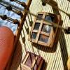
The location, pattern, and style of windows was taken from the photos and the appropriate decals applied to the deckhouse as before. Here is how the deckhouse looked before installation.
On top of the boat deckhouse was the deck piece for the next deck up, the Lido Deck. In this photo you can see the construction sequence. After the rough cut piece was refined slightly to fit exactly to match the lower decks, the decking paper was applied, making sure to line up the plank seams with the centerline. The edge of the paper was trimmed back to the edge of the wood then an edge strip of 0.125” styrene was put on. Openings for companionways were cut out and stairways were test fit. The Lido Deck house has been sheathed and its position is being adjusted.
At the bow end of the Boat Deck house the margin plank is being applied. Here you can see what a difference that simple strip of paper makes. Without it the house looks like it ‘floats’ a little above the deck. With it, the deckhouse settles down and becomes an integral part of the whole. At least to my eye. It also gives a nice, polished look to the edges of the stairway openings in the deck. To get it to take the curves, the strip was misted with water and allowed to relax before glue was applied. Working in small increments it was worked around the base of the deckhouse and along the companionway edges.
Here is some of the reason for all the test fittings of decks and deck houses. The sheathing has to flow seamlessly from around the Promenade Deck house up past the Boat Deck to the overhanging edge of the Lido Deck, and then around to form the free-standing bulwark at the forward face. I got them all to line up almost exactly, but some joints had to be filled with a little Squadron white putty and sanded flush. The difference in texture that you can see will be blended and smoothed with later coats of finish.
Toward the stern the same techniques have been used. The walls to the sides of the second class pool have multiple tight curves, but by heating the sheathing strips with a hair dryer they conformed without a lot of effort.
In the photo you can see the side of a grey strip overhanging the boat deck windows. It seems to be a narrow walkway area to service the lifeboats, their davits and winches. Some of the davit fittings are balanced on the edge to check alignment and fitting. I have no idea why the walkway ends without reaching the forward end of the Boat Deck, and is replaced with two short stools to support the forward davits, but that is how it looks on the plans and photos.
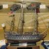
So here she is with the Boat Deck in place and most of its details done and with the Lido Deck under construction.
Construction in the shipyard is a bit slow at the moment, so the next installments should be out soon.
Dan
-
 shipmodel got a reaction from ScottRC in SS Andrea Doria 1952 by shipmodel - FINISHED - 1/16" scale
Build log 7 – more bow details, boat deck
Thank you Greg and Nils. I'm not sure that the model merits three "wows" yet, but I will keep trying.
I continued the build by turning to some of the detail work that had been put off till more of the coarse work of building up the decks was done. These included the external anchor and the ship’s name. The plans and photos show that the anchor is set in a square depression with rounded corners that is shallowest at the upper edge and deeper at the bottom. The color separation line crosses it.
I made up a quick template from a plastic strip and scribed the tilted outline on both sides of the hull. With a flat-bottomed carving bit and a light touch I carefully removed plastic and wood until I had the depression that I wanted. The bottom was smoothed and a hole was drilled to take the mounting post of the anchor fitting. The depression was painted in black and white to match the hull, then the anchor and hawse pipe fitting was pinned and glued in place.
The name was another custom decal created in my computer. Photos of the ship show that the letters were raised brass, which I could not duplicate, but Photoshop let me select a gold tone for the letters with a narrow black shadow effect that makes them stand out.
For the draft marks at the waterline I located a decal set from Europe in 1:200 scale using the correct Roman numerals. These were applied vertically port and starboard near the bow and at the stern up the rudder post. Since the carrier was clear no edge painting was needed.
The Plimsol Line marking could not be sourced, so it was custom made. I researched a number of sites for the design and learned that there is different lettering depending on the country of registry of the ship. The “R” and “I” indicate an Italian ship. Because the symbols are white, and I don’t have a Cartograph printer, I had to use white decal film, so the black and red colors were also printed. It took a number of experiments to get the right shades. The best one was printed out, set in place, and the cut white edges hidden and feathered with paint.
On the bow working deck I made up the anchor machinery. I never could find a clear photo of these fittings on the Doria, but I did find one taken of them on a contemporary Italian Line ship, so I used those as the patterns. First the hawse pipe openings were located and drilled out about half an inch deep. The pipes were painted flat black before metal hawse lips were painted and installed.
The anchor chains run through chain brakes, then aft along a chute with raised sides, then around the anchor winch and down an elbow fitting to the chain locker below. A combination of several pieces of various metal fittings and scratch-made plastic elements, and an overall coat of grey paint, were needed to make it look like the photos. After pinning and gluing the winches down a set of margin planks were added to make them look built into the deck.
The spare stockless anchor rests against the forward wall of the deck house and is secured by a narrow strap.
The next deck up was the boat deck which turned out to have a surprise for me. When I stacked the rough decks and deckhouses to see how they fit, something didn’t look right. It took me about a week to realize that it was the boat deck. I had assumed that all of the decks were the same height, but the plans showed that the boat deck was some 2 feet taller. This then required a quick scramble to add another 1/8” sheet of basswood to the deckhouse. Lots of clamps were used to get a tight fit between the pieces.
All of the edges were shaped to final lines with a benchtop 6” sanding disc, which also insured that they were vertical. Notches were cut for doorways as indicated on the plans. These entryways now made sense, because they now had the room for short stairways to the doors leading to a raised floor.
The sheathing is 0.020” styrene sheet which is easily cut with a knife and straightedge. I find that cutting all the way through leaves a burr along one edge, so I scribe the line about halfway through and then bend and snap it the rest of the way. Very little cleanup is needed with a medium grit sanding block.
The sheathing is glued to the wood with medium thickness cyano. I lay a bead of it direct from the bottle onto the plastic, which I have indicated with the grey line. On the plastic it stays liquid until brought into contact with the wood, giving me enough time to position it carefully. I have to move quickly, but with a bit of practice it goes along pretty smoothly.
Most of the raised doorways only needed a small piece of HO scale plastic house siding to simulate steps, but a few had small landings. The platform was built of sheathed wood with photoetched railings and steps.
Handrails were made from 0.020” brass rod, which seems to be a bit straighter and stiffer than identical sized brass wire, while still being malleable enough to bend around curves. Pieces were cut to fit just short of the space between doorways or the end of a deckhouse section. The handrail supports are wire, for flexibility, but 0.016”. I first draw a horizontal line along the side of the deckhouse with a compass set to the scale equivalent of 42 inches from the deck.
Just below the line I drill holes for the supports at an angle, then insert the wire and clip it off leaving a stub which then holds the rail to the deckhouse wall. A drop of thin cyano is applied with a toothpick, which wicks into the hole and around the support and railing, securing everything. When all the supports for a section of railing are done and the glue dry, the stubs are clipped off as short as I can with a cuticle nipper from the cosmetics section of my local drugstore.
The location, pattern, and style of windows was taken from the photos and the appropriate decals applied to the deckhouse as before. Here is how the deckhouse looked before installation.
On top of the boat deckhouse was the deck piece for the next deck up, the Lido Deck. In this photo you can see the construction sequence. After the rough cut piece was refined slightly to fit exactly to match the lower decks, the decking paper was applied, making sure to line up the plank seams with the centerline. The edge of the paper was trimmed back to the edge of the wood then an edge strip of 0.125” styrene was put on. Openings for companionways were cut out and stairways were test fit. The Lido Deck house has been sheathed and its position is being adjusted.
At the bow end of the Boat Deck house the margin plank is being applied. Here you can see what a difference that simple strip of paper makes. Without it the house looks like it ‘floats’ a little above the deck. With it, the deckhouse settles down and becomes an integral part of the whole. At least to my eye. It also gives a nice, polished look to the edges of the stairway openings in the deck. To get it to take the curves, the strip was misted with water and allowed to relax before glue was applied. Working in small increments it was worked around the base of the deckhouse and along the companionway edges.
Here is some of the reason for all the test fittings of decks and deck houses. The sheathing has to flow seamlessly from around the Promenade Deck house up past the Boat Deck to the overhanging edge of the Lido Deck, and then around to form the free-standing bulwark at the forward face. I got them all to line up almost exactly, but some joints had to be filled with a little Squadron white putty and sanded flush. The difference in texture that you can see will be blended and smoothed with later coats of finish.
Toward the stern the same techniques have been used. The walls to the sides of the second class pool have multiple tight curves, but by heating the sheathing strips with a hair dryer they conformed without a lot of effort.
In the photo you can see the side of a grey strip overhanging the boat deck windows. It seems to be a narrow walkway area to service the lifeboats, their davits and winches. Some of the davit fittings are balanced on the edge to check alignment and fitting. I have no idea why the walkway ends without reaching the forward end of the Boat Deck, and is replaced with two short stools to support the forward davits, but that is how it looks on the plans and photos.
So here she is with the Boat Deck in place and most of its details done and with the Lido Deck under construction.
Construction in the shipyard is a bit slow at the moment, so the next installments should be out soon.
Dan
-
 shipmodel got a reaction from Mirabell61 in SS Kaiser Wilhelm der Grosse 1897 by Mirabell61 - FINISHED - scale 1:144 - POF - first German four stacker of the Norddeutscher Lloyd line
Hi Nils -
I thought that I had read through this log, but somehow I missed it. Seriously good work, my friend!
Spent an enjoyable two hours with it and found several ideas and techniques that will work their way into my own projects. It was fascinating to see how the techniques that we use are both similar and different because of the scales that we are working in.
I am now hooked into the log for instant updates.
Dan
-
 shipmodel got a reaction from Omega1234 in SS Kaiser Wilhelm der Grosse 1897 by Mirabell61 - FINISHED - scale 1:144 - POF - first German four stacker of the Norddeutscher Lloyd line
Hi Nils -
I thought that I had read through this log, but somehow I missed it. Seriously good work, my friend!
Spent an enjoyable two hours with it and found several ideas and techniques that will work their way into my own projects. It was fascinating to see how the techniques that we use are both similar and different because of the scales that we are working in.
I am now hooked into the log for instant updates.
Dan
-
 shipmodel reacted to Mirabell61 in SS Kaiser Wilhelm der Grosse 1897 by Mirabell61 - FINISHED - scale 1:144 - POF - first German four stacker of the Norddeutscher Lloyd line
Thank you Denis,
I`m just working on the forecastle anchor / chain tubes (6 mm brass tubes), they will have to be faired and equipped wih flanges to sides and deck afterwards, but have to be dry fitted now in case some adjustments have to be made inside the ship.
The forecastle deck comprises 3 shaped parts....
The scetch (partial section) shows the arrangement of the other decks, at least how I intend to do them
Nils
Little update :
-
shipmodel reacted to Mirabell61 in SS Andrea Doria 1952 by shipmodel - FINISHED - 1/16" scale
excellent work Dan,
amazing your use of printing Details of the superstructure and positioning These per decals, all Looks very precise and well thought over. The combination of Wood, styrene, printed Sheets, and etched parts really open fine mini-scale possibilities. These techniques may be tempting for others....., thanks for sharing
Nils
-
 shipmodel got a reaction from ccoyle in SS Andrea Doria 1952 by shipmodel - FINISHED - 1/16" scale
Build log 7 – more bow details, boat deck
Thank you Greg and Nils. I'm not sure that the model merits three "wows" yet, but I will keep trying.
I continued the build by turning to some of the detail work that had been put off till more of the coarse work of building up the decks was done. These included the external anchor and the ship’s name. The plans and photos show that the anchor is set in a square depression with rounded corners that is shallowest at the upper edge and deeper at the bottom. The color separation line crosses it.
I made up a quick template from a plastic strip and scribed the tilted outline on both sides of the hull. With a flat-bottomed carving bit and a light touch I carefully removed plastic and wood until I had the depression that I wanted. The bottom was smoothed and a hole was drilled to take the mounting post of the anchor fitting. The depression was painted in black and white to match the hull, then the anchor and hawse pipe fitting was pinned and glued in place.
The name was another custom decal created in my computer. Photos of the ship show that the letters were raised brass, which I could not duplicate, but Photoshop let me select a gold tone for the letters with a narrow black shadow effect that makes them stand out.
For the draft marks at the waterline I located a decal set from Europe in 1:200 scale using the correct Roman numerals. These were applied vertically port and starboard near the bow and at the stern up the rudder post. Since the carrier was clear no edge painting was needed.
The Plimsol Line marking could not be sourced, so it was custom made. I researched a number of sites for the design and learned that there is different lettering depending on the country of registry of the ship. The “R” and “I” indicate an Italian ship. Because the symbols are white, and I don’t have a Cartograph printer, I had to use white decal film, so the black and red colors were also printed. It took a number of experiments to get the right shades. The best one was printed out, set in place, and the cut white edges hidden and feathered with paint.
On the bow working deck I made up the anchor machinery. I never could find a clear photo of these fittings on the Doria, but I did find one taken of them on a contemporary Italian Line ship, so I used those as the patterns. First the hawse pipe openings were located and drilled out about half an inch deep. The pipes were painted flat black before metal hawse lips were painted and installed.
The anchor chains run through chain brakes, then aft along a chute with raised sides, then around the anchor winch and down an elbow fitting to the chain locker below. A combination of several pieces of various metal fittings and scratch-made plastic elements, and an overall coat of grey paint, were needed to make it look like the photos. After pinning and gluing the winches down a set of margin planks were added to make them look built into the deck.
The spare stockless anchor rests against the forward wall of the deck house and is secured by a narrow strap.
The next deck up was the boat deck which turned out to have a surprise for me. When I stacked the rough decks and deckhouses to see how they fit, something didn’t look right. It took me about a week to realize that it was the boat deck. I had assumed that all of the decks were the same height, but the plans showed that the boat deck was some 2 feet taller. This then required a quick scramble to add another 1/8” sheet of basswood to the deckhouse. Lots of clamps were used to get a tight fit between the pieces.
All of the edges were shaped to final lines with a benchtop 6” sanding disc, which also insured that they were vertical. Notches were cut for doorways as indicated on the plans. These entryways now made sense, because they now had the room for short stairways to the doors leading to a raised floor.
The sheathing is 0.020” styrene sheet which is easily cut with a knife and straightedge. I find that cutting all the way through leaves a burr along one edge, so I scribe the line about halfway through and then bend and snap it the rest of the way. Very little cleanup is needed with a medium grit sanding block.
The sheathing is glued to the wood with medium thickness cyano. I lay a bead of it direct from the bottle onto the plastic, which I have indicated with the grey line. On the plastic it stays liquid until brought into contact with the wood, giving me enough time to position it carefully. I have to move quickly, but with a bit of practice it goes along pretty smoothly.
Most of the raised doorways only needed a small piece of HO scale plastic house siding to simulate steps, but a few had small landings. The platform was built of sheathed wood with photoetched railings and steps.
Handrails were made from 0.020” brass rod, which seems to be a bit straighter and stiffer than identical sized brass wire, while still being malleable enough to bend around curves. Pieces were cut to fit just short of the space between doorways or the end of a deckhouse section. The handrail supports are wire, for flexibility, but 0.016”. I first draw a horizontal line along the side of the deckhouse with a compass set to the scale equivalent of 42 inches from the deck.
Just below the line I drill holes for the supports at an angle, then insert the wire and clip it off leaving a stub which then holds the rail to the deckhouse wall. A drop of thin cyano is applied with a toothpick, which wicks into the hole and around the support and railing, securing everything. When all the supports for a section of railing are done and the glue dry, the stubs are clipped off as short as I can with a cuticle nipper from the cosmetics section of my local drugstore.
The location, pattern, and style of windows was taken from the photos and the appropriate decals applied to the deckhouse as before. Here is how the deckhouse looked before installation.
On top of the boat deckhouse was the deck piece for the next deck up, the Lido Deck. In this photo you can see the construction sequence. After the rough cut piece was refined slightly to fit exactly to match the lower decks, the decking paper was applied, making sure to line up the plank seams with the centerline. The edge of the paper was trimmed back to the edge of the wood then an edge strip of 0.125” styrene was put on. Openings for companionways were cut out and stairways were test fit. The Lido Deck house has been sheathed and its position is being adjusted.
At the bow end of the Boat Deck house the margin plank is being applied. Here you can see what a difference that simple strip of paper makes. Without it the house looks like it ‘floats’ a little above the deck. With it, the deckhouse settles down and becomes an integral part of the whole. At least to my eye. It also gives a nice, polished look to the edges of the stairway openings in the deck. To get it to take the curves, the strip was misted with water and allowed to relax before glue was applied. Working in small increments it was worked around the base of the deckhouse and along the companionway edges.
Here is some of the reason for all the test fittings of decks and deck houses. The sheathing has to flow seamlessly from around the Promenade Deck house up past the Boat Deck to the overhanging edge of the Lido Deck, and then around to form the free-standing bulwark at the forward face. I got them all to line up almost exactly, but some joints had to be filled with a little Squadron white putty and sanded flush. The difference in texture that you can see will be blended and smoothed with later coats of finish.
Toward the stern the same techniques have been used. The walls to the sides of the second class pool have multiple tight curves, but by heating the sheathing strips with a hair dryer they conformed without a lot of effort.
In the photo you can see the side of a grey strip overhanging the boat deck windows. It seems to be a narrow walkway area to service the lifeboats, their davits and winches. Some of the davit fittings are balanced on the edge to check alignment and fitting. I have no idea why the walkway ends without reaching the forward end of the Boat Deck, and is replaced with two short stools to support the forward davits, but that is how it looks on the plans and photos.
So here she is with the Boat Deck in place and most of its details done and with the Lido Deck under construction.
Construction in the shipyard is a bit slow at the moment, so the next installments should be out soon.
Dan
-
 shipmodel got a reaction from Leo-zd in SS Andrea Doria 1952 by shipmodel - FINISHED - 1/16" scale
Build log 7 – more bow details, boat deck
Thank you Greg and Nils. I'm not sure that the model merits three "wows" yet, but I will keep trying.
I continued the build by turning to some of the detail work that had been put off till more of the coarse work of building up the decks was done. These included the external anchor and the ship’s name. The plans and photos show that the anchor is set in a square depression with rounded corners that is shallowest at the upper edge and deeper at the bottom. The color separation line crosses it.
I made up a quick template from a plastic strip and scribed the tilted outline on both sides of the hull. With a flat-bottomed carving bit and a light touch I carefully removed plastic and wood until I had the depression that I wanted. The bottom was smoothed and a hole was drilled to take the mounting post of the anchor fitting. The depression was painted in black and white to match the hull, then the anchor and hawse pipe fitting was pinned and glued in place.
The name was another custom decal created in my computer. Photos of the ship show that the letters were raised brass, which I could not duplicate, but Photoshop let me select a gold tone for the letters with a narrow black shadow effect that makes them stand out.
For the draft marks at the waterline I located a decal set from Europe in 1:200 scale using the correct Roman numerals. These were applied vertically port and starboard near the bow and at the stern up the rudder post. Since the carrier was clear no edge painting was needed.
The Plimsol Line marking could not be sourced, so it was custom made. I researched a number of sites for the design and learned that there is different lettering depending on the country of registry of the ship. The “R” and “I” indicate an Italian ship. Because the symbols are white, and I don’t have a Cartograph printer, I had to use white decal film, so the black and red colors were also printed. It took a number of experiments to get the right shades. The best one was printed out, set in place, and the cut white edges hidden and feathered with paint.
On the bow working deck I made up the anchor machinery. I never could find a clear photo of these fittings on the Doria, but I did find one taken of them on a contemporary Italian Line ship, so I used those as the patterns. First the hawse pipe openings were located and drilled out about half an inch deep. The pipes were painted flat black before metal hawse lips were painted and installed.
The anchor chains run through chain brakes, then aft along a chute with raised sides, then around the anchor winch and down an elbow fitting to the chain locker below. A combination of several pieces of various metal fittings and scratch-made plastic elements, and an overall coat of grey paint, were needed to make it look like the photos. After pinning and gluing the winches down a set of margin planks were added to make them look built into the deck.
The spare stockless anchor rests against the forward wall of the deck house and is secured by a narrow strap.
The next deck up was the boat deck which turned out to have a surprise for me. When I stacked the rough decks and deckhouses to see how they fit, something didn’t look right. It took me about a week to realize that it was the boat deck. I had assumed that all of the decks were the same height, but the plans showed that the boat deck was some 2 feet taller. This then required a quick scramble to add another 1/8” sheet of basswood to the deckhouse. Lots of clamps were used to get a tight fit between the pieces.
All of the edges were shaped to final lines with a benchtop 6” sanding disc, which also insured that they were vertical. Notches were cut for doorways as indicated on the plans. These entryways now made sense, because they now had the room for short stairways to the doors leading to a raised floor.
The sheathing is 0.020” styrene sheet which is easily cut with a knife and straightedge. I find that cutting all the way through leaves a burr along one edge, so I scribe the line about halfway through and then bend and snap it the rest of the way. Very little cleanup is needed with a medium grit sanding block.
The sheathing is glued to the wood with medium thickness cyano. I lay a bead of it direct from the bottle onto the plastic, which I have indicated with the grey line. On the plastic it stays liquid until brought into contact with the wood, giving me enough time to position it carefully. I have to move quickly, but with a bit of practice it goes along pretty smoothly.
Most of the raised doorways only needed a small piece of HO scale plastic house siding to simulate steps, but a few had small landings. The platform was built of sheathed wood with photoetched railings and steps.
Handrails were made from 0.020” brass rod, which seems to be a bit straighter and stiffer than identical sized brass wire, while still being malleable enough to bend around curves. Pieces were cut to fit just short of the space between doorways or the end of a deckhouse section. The handrail supports are wire, for flexibility, but 0.016”. I first draw a horizontal line along the side of the deckhouse with a compass set to the scale equivalent of 42 inches from the deck.
Just below the line I drill holes for the supports at an angle, then insert the wire and clip it off leaving a stub which then holds the rail to the deckhouse wall. A drop of thin cyano is applied with a toothpick, which wicks into the hole and around the support and railing, securing everything. When all the supports for a section of railing are done and the glue dry, the stubs are clipped off as short as I can with a cuticle nipper from the cosmetics section of my local drugstore.
The location, pattern, and style of windows was taken from the photos and the appropriate decals applied to the deckhouse as before. Here is how the deckhouse looked before installation.
On top of the boat deckhouse was the deck piece for the next deck up, the Lido Deck. In this photo you can see the construction sequence. After the rough cut piece was refined slightly to fit exactly to match the lower decks, the decking paper was applied, making sure to line up the plank seams with the centerline. The edge of the paper was trimmed back to the edge of the wood then an edge strip of 0.125” styrene was put on. Openings for companionways were cut out and stairways were test fit. The Lido Deck house has been sheathed and its position is being adjusted.
At the bow end of the Boat Deck house the margin plank is being applied. Here you can see what a difference that simple strip of paper makes. Without it the house looks like it ‘floats’ a little above the deck. With it, the deckhouse settles down and becomes an integral part of the whole. At least to my eye. It also gives a nice, polished look to the edges of the stairway openings in the deck. To get it to take the curves, the strip was misted with water and allowed to relax before glue was applied. Working in small increments it was worked around the base of the deckhouse and along the companionway edges.
Here is some of the reason for all the test fittings of decks and deck houses. The sheathing has to flow seamlessly from around the Promenade Deck house up past the Boat Deck to the overhanging edge of the Lido Deck, and then around to form the free-standing bulwark at the forward face. I got them all to line up almost exactly, but some joints had to be filled with a little Squadron white putty and sanded flush. The difference in texture that you can see will be blended and smoothed with later coats of finish.
Toward the stern the same techniques have been used. The walls to the sides of the second class pool have multiple tight curves, but by heating the sheathing strips with a hair dryer they conformed without a lot of effort.
In the photo you can see the side of a grey strip overhanging the boat deck windows. It seems to be a narrow walkway area to service the lifeboats, their davits and winches. Some of the davit fittings are balanced on the edge to check alignment and fitting. I have no idea why the walkway ends without reaching the forward end of the Boat Deck, and is replaced with two short stools to support the forward davits, but that is how it looks on the plans and photos.
So here she is with the Boat Deck in place and most of its details done and with the Lido Deck under construction.
Construction in the shipyard is a bit slow at the moment, so the next installments should be out soon.
Dan
-
 shipmodel got a reaction from Canute in SS Andrea Doria 1952 by shipmodel - FINISHED - 1/16" scale
Build log 7 – more bow details, boat deck
Thank you Greg and Nils. I'm not sure that the model merits three "wows" yet, but I will keep trying.
I continued the build by turning to some of the detail work that had been put off till more of the coarse work of building up the decks was done. These included the external anchor and the ship’s name. The plans and photos show that the anchor is set in a square depression with rounded corners that is shallowest at the upper edge and deeper at the bottom. The color separation line crosses it.
I made up a quick template from a plastic strip and scribed the tilted outline on both sides of the hull. With a flat-bottomed carving bit and a light touch I carefully removed plastic and wood until I had the depression that I wanted. The bottom was smoothed and a hole was drilled to take the mounting post of the anchor fitting. The depression was painted in black and white to match the hull, then the anchor and hawse pipe fitting was pinned and glued in place.
The name was another custom decal created in my computer. Photos of the ship show that the letters were raised brass, which I could not duplicate, but Photoshop let me select a gold tone for the letters with a narrow black shadow effect that makes them stand out.
For the draft marks at the waterline I located a decal set from Europe in 1:200 scale using the correct Roman numerals. These were applied vertically port and starboard near the bow and at the stern up the rudder post. Since the carrier was clear no edge painting was needed.
The Plimsol Line marking could not be sourced, so it was custom made. I researched a number of sites for the design and learned that there is different lettering depending on the country of registry of the ship. The “R” and “I” indicate an Italian ship. Because the symbols are white, and I don’t have a Cartograph printer, I had to use white decal film, so the black and red colors were also printed. It took a number of experiments to get the right shades. The best one was printed out, set in place, and the cut white edges hidden and feathered with paint.
On the bow working deck I made up the anchor machinery. I never could find a clear photo of these fittings on the Doria, but I did find one taken of them on a contemporary Italian Line ship, so I used those as the patterns. First the hawse pipe openings were located and drilled out about half an inch deep. The pipes were painted flat black before metal hawse lips were painted and installed.
The anchor chains run through chain brakes, then aft along a chute with raised sides, then around the anchor winch and down an elbow fitting to the chain locker below. A combination of several pieces of various metal fittings and scratch-made plastic elements, and an overall coat of grey paint, were needed to make it look like the photos. After pinning and gluing the winches down a set of margin planks were added to make them look built into the deck.
The spare stockless anchor rests against the forward wall of the deck house and is secured by a narrow strap.
The next deck up was the boat deck which turned out to have a surprise for me. When I stacked the rough decks and deckhouses to see how they fit, something didn’t look right. It took me about a week to realize that it was the boat deck. I had assumed that all of the decks were the same height, but the plans showed that the boat deck was some 2 feet taller. This then required a quick scramble to add another 1/8” sheet of basswood to the deckhouse. Lots of clamps were used to get a tight fit between the pieces.
All of the edges were shaped to final lines with a benchtop 6” sanding disc, which also insured that they were vertical. Notches were cut for doorways as indicated on the plans. These entryways now made sense, because they now had the room for short stairways to the doors leading to a raised floor.
The sheathing is 0.020” styrene sheet which is easily cut with a knife and straightedge. I find that cutting all the way through leaves a burr along one edge, so I scribe the line about halfway through and then bend and snap it the rest of the way. Very little cleanup is needed with a medium grit sanding block.
The sheathing is glued to the wood with medium thickness cyano. I lay a bead of it direct from the bottle onto the plastic, which I have indicated with the grey line. On the plastic it stays liquid until brought into contact with the wood, giving me enough time to position it carefully. I have to move quickly, but with a bit of practice it goes along pretty smoothly.
Most of the raised doorways only needed a small piece of HO scale plastic house siding to simulate steps, but a few had small landings. The platform was built of sheathed wood with photoetched railings and steps.
Handrails were made from 0.020” brass rod, which seems to be a bit straighter and stiffer than identical sized brass wire, while still being malleable enough to bend around curves. Pieces were cut to fit just short of the space between doorways or the end of a deckhouse section. The handrail supports are wire, for flexibility, but 0.016”. I first draw a horizontal line along the side of the deckhouse with a compass set to the scale equivalent of 42 inches from the deck.
Just below the line I drill holes for the supports at an angle, then insert the wire and clip it off leaving a stub which then holds the rail to the deckhouse wall. A drop of thin cyano is applied with a toothpick, which wicks into the hole and around the support and railing, securing everything. When all the supports for a section of railing are done and the glue dry, the stubs are clipped off as short as I can with a cuticle nipper from the cosmetics section of my local drugstore.
The location, pattern, and style of windows was taken from the photos and the appropriate decals applied to the deckhouse as before. Here is how the deckhouse looked before installation.
On top of the boat deckhouse was the deck piece for the next deck up, the Lido Deck. In this photo you can see the construction sequence. After the rough cut piece was refined slightly to fit exactly to match the lower decks, the decking paper was applied, making sure to line up the plank seams with the centerline. The edge of the paper was trimmed back to the edge of the wood then an edge strip of 0.125” styrene was put on. Openings for companionways were cut out and stairways were test fit. The Lido Deck house has been sheathed and its position is being adjusted.
At the bow end of the Boat Deck house the margin plank is being applied. Here you can see what a difference that simple strip of paper makes. Without it the house looks like it ‘floats’ a little above the deck. With it, the deckhouse settles down and becomes an integral part of the whole. At least to my eye. It also gives a nice, polished look to the edges of the stairway openings in the deck. To get it to take the curves, the strip was misted with water and allowed to relax before glue was applied. Working in small increments it was worked around the base of the deckhouse and along the companionway edges.
Here is some of the reason for all the test fittings of decks and deck houses. The sheathing has to flow seamlessly from around the Promenade Deck house up past the Boat Deck to the overhanging edge of the Lido Deck, and then around to form the free-standing bulwark at the forward face. I got them all to line up almost exactly, but some joints had to be filled with a little Squadron white putty and sanded flush. The difference in texture that you can see will be blended and smoothed with later coats of finish.
Toward the stern the same techniques have been used. The walls to the sides of the second class pool have multiple tight curves, but by heating the sheathing strips with a hair dryer they conformed without a lot of effort.
In the photo you can see the side of a grey strip overhanging the boat deck windows. It seems to be a narrow walkway area to service the lifeboats, their davits and winches. Some of the davit fittings are balanced on the edge to check alignment and fitting. I have no idea why the walkway ends without reaching the forward end of the Boat Deck, and is replaced with two short stools to support the forward davits, but that is how it looks on the plans and photos.
So here she is with the Boat Deck in place and most of its details done and with the Lido Deck under construction.
Construction in the shipyard is a bit slow at the moment, so the next installments should be out soon.
Dan
-
 shipmodel got a reaction from usedtosail in SS Andrea Doria 1952 by shipmodel - FINISHED - 1/16" scale
Build log 7 – more bow details, boat deck
Thank you Greg and Nils. I'm not sure that the model merits three "wows" yet, but I will keep trying.
I continued the build by turning to some of the detail work that had been put off till more of the coarse work of building up the decks was done. These included the external anchor and the ship’s name. The plans and photos show that the anchor is set in a square depression with rounded corners that is shallowest at the upper edge and deeper at the bottom. The color separation line crosses it.
I made up a quick template from a plastic strip and scribed the tilted outline on both sides of the hull. With a flat-bottomed carving bit and a light touch I carefully removed plastic and wood until I had the depression that I wanted. The bottom was smoothed and a hole was drilled to take the mounting post of the anchor fitting. The depression was painted in black and white to match the hull, then the anchor and hawse pipe fitting was pinned and glued in place.
The name was another custom decal created in my computer. Photos of the ship show that the letters were raised brass, which I could not duplicate, but Photoshop let me select a gold tone for the letters with a narrow black shadow effect that makes them stand out.
For the draft marks at the waterline I located a decal set from Europe in 1:200 scale using the correct Roman numerals. These were applied vertically port and starboard near the bow and at the stern up the rudder post. Since the carrier was clear no edge painting was needed.
The Plimsol Line marking could not be sourced, so it was custom made. I researched a number of sites for the design and learned that there is different lettering depending on the country of registry of the ship. The “R” and “I” indicate an Italian ship. Because the symbols are white, and I don’t have a Cartograph printer, I had to use white decal film, so the black and red colors were also printed. It took a number of experiments to get the right shades. The best one was printed out, set in place, and the cut white edges hidden and feathered with paint.
On the bow working deck I made up the anchor machinery. I never could find a clear photo of these fittings on the Doria, but I did find one taken of them on a contemporary Italian Line ship, so I used those as the patterns. First the hawse pipe openings were located and drilled out about half an inch deep. The pipes were painted flat black before metal hawse lips were painted and installed.
The anchor chains run through chain brakes, then aft along a chute with raised sides, then around the anchor winch and down an elbow fitting to the chain locker below. A combination of several pieces of various metal fittings and scratch-made plastic elements, and an overall coat of grey paint, were needed to make it look like the photos. After pinning and gluing the winches down a set of margin planks were added to make them look built into the deck.
The spare stockless anchor rests against the forward wall of the deck house and is secured by a narrow strap.
The next deck up was the boat deck which turned out to have a surprise for me. When I stacked the rough decks and deckhouses to see how they fit, something didn’t look right. It took me about a week to realize that it was the boat deck. I had assumed that all of the decks were the same height, but the plans showed that the boat deck was some 2 feet taller. This then required a quick scramble to add another 1/8” sheet of basswood to the deckhouse. Lots of clamps were used to get a tight fit between the pieces.
All of the edges were shaped to final lines with a benchtop 6” sanding disc, which also insured that they were vertical. Notches were cut for doorways as indicated on the plans. These entryways now made sense, because they now had the room for short stairways to the doors leading to a raised floor.
The sheathing is 0.020” styrene sheet which is easily cut with a knife and straightedge. I find that cutting all the way through leaves a burr along one edge, so I scribe the line about halfway through and then bend and snap it the rest of the way. Very little cleanup is needed with a medium grit sanding block.
The sheathing is glued to the wood with medium thickness cyano. I lay a bead of it direct from the bottle onto the plastic, which I have indicated with the grey line. On the plastic it stays liquid until brought into contact with the wood, giving me enough time to position it carefully. I have to move quickly, but with a bit of practice it goes along pretty smoothly.
Most of the raised doorways only needed a small piece of HO scale plastic house siding to simulate steps, but a few had small landings. The platform was built of sheathed wood with photoetched railings and steps.
Handrails were made from 0.020” brass rod, which seems to be a bit straighter and stiffer than identical sized brass wire, while still being malleable enough to bend around curves. Pieces were cut to fit just short of the space between doorways or the end of a deckhouse section. The handrail supports are wire, for flexibility, but 0.016”. I first draw a horizontal line along the side of the deckhouse with a compass set to the scale equivalent of 42 inches from the deck.
Just below the line I drill holes for the supports at an angle, then insert the wire and clip it off leaving a stub which then holds the rail to the deckhouse wall. A drop of thin cyano is applied with a toothpick, which wicks into the hole and around the support and railing, securing everything. When all the supports for a section of railing are done and the glue dry, the stubs are clipped off as short as I can with a cuticle nipper from the cosmetics section of my local drugstore.
The location, pattern, and style of windows was taken from the photos and the appropriate decals applied to the deckhouse as before. Here is how the deckhouse looked before installation.
On top of the boat deckhouse was the deck piece for the next deck up, the Lido Deck. In this photo you can see the construction sequence. After the rough cut piece was refined slightly to fit exactly to match the lower decks, the decking paper was applied, making sure to line up the plank seams with the centerline. The edge of the paper was trimmed back to the edge of the wood then an edge strip of 0.125” styrene was put on. Openings for companionways were cut out and stairways were test fit. The Lido Deck house has been sheathed and its position is being adjusted.
At the bow end of the Boat Deck house the margin plank is being applied. Here you can see what a difference that simple strip of paper makes. Without it the house looks like it ‘floats’ a little above the deck. With it, the deckhouse settles down and becomes an integral part of the whole. At least to my eye. It also gives a nice, polished look to the edges of the stairway openings in the deck. To get it to take the curves, the strip was misted with water and allowed to relax before glue was applied. Working in small increments it was worked around the base of the deckhouse and along the companionway edges.
Here is some of the reason for all the test fittings of decks and deck houses. The sheathing has to flow seamlessly from around the Promenade Deck house up past the Boat Deck to the overhanging edge of the Lido Deck, and then around to form the free-standing bulwark at the forward face. I got them all to line up almost exactly, but some joints had to be filled with a little Squadron white putty and sanded flush. The difference in texture that you can see will be blended and smoothed with later coats of finish.
Toward the stern the same techniques have been used. The walls to the sides of the second class pool have multiple tight curves, but by heating the sheathing strips with a hair dryer they conformed without a lot of effort.
In the photo you can see the side of a grey strip overhanging the boat deck windows. It seems to be a narrow walkway area to service the lifeboats, their davits and winches. Some of the davit fittings are balanced on the edge to check alignment and fitting. I have no idea why the walkway ends without reaching the forward end of the Boat Deck, and is replaced with two short stools to support the forward davits, but that is how it looks on the plans and photos.
So here she is with the Boat Deck in place and most of its details done and with the Lido Deck under construction.
Construction in the shipyard is a bit slow at the moment, so the next installments should be out soon.
Dan
-
 shipmodel got a reaction from BenF89 in SS Andrea Doria 1952 by shipmodel - FINISHED - 1/16" scale
Build log 7 – more bow details, boat deck
Thank you Greg and Nils. I'm not sure that the model merits three "wows" yet, but I will keep trying.
I continued the build by turning to some of the detail work that had been put off till more of the coarse work of building up the decks was done. These included the external anchor and the ship’s name. The plans and photos show that the anchor is set in a square depression with rounded corners that is shallowest at the upper edge and deeper at the bottom. The color separation line crosses it.
I made up a quick template from a plastic strip and scribed the tilted outline on both sides of the hull. With a flat-bottomed carving bit and a light touch I carefully removed plastic and wood until I had the depression that I wanted. The bottom was smoothed and a hole was drilled to take the mounting post of the anchor fitting. The depression was painted in black and white to match the hull, then the anchor and hawse pipe fitting was pinned and glued in place.
The name was another custom decal created in my computer. Photos of the ship show that the letters were raised brass, which I could not duplicate, but Photoshop let me select a gold tone for the letters with a narrow black shadow effect that makes them stand out.
For the draft marks at the waterline I located a decal set from Europe in 1:200 scale using the correct Roman numerals. These were applied vertically port and starboard near the bow and at the stern up the rudder post. Since the carrier was clear no edge painting was needed.
The Plimsol Line marking could not be sourced, so it was custom made. I researched a number of sites for the design and learned that there is different lettering depending on the country of registry of the ship. The “R” and “I” indicate an Italian ship. Because the symbols are white, and I don’t have a Cartograph printer, I had to use white decal film, so the black and red colors were also printed. It took a number of experiments to get the right shades. The best one was printed out, set in place, and the cut white edges hidden and feathered with paint.
On the bow working deck I made up the anchor machinery. I never could find a clear photo of these fittings on the Doria, but I did find one taken of them on a contemporary Italian Line ship, so I used those as the patterns. First the hawse pipe openings were located and drilled out about half an inch deep. The pipes were painted flat black before metal hawse lips were painted and installed.
The anchor chains run through chain brakes, then aft along a chute with raised sides, then around the anchor winch and down an elbow fitting to the chain locker below. A combination of several pieces of various metal fittings and scratch-made plastic elements, and an overall coat of grey paint, were needed to make it look like the photos. After pinning and gluing the winches down a set of margin planks were added to make them look built into the deck.
The spare stockless anchor rests against the forward wall of the deck house and is secured by a narrow strap.
The next deck up was the boat deck which turned out to have a surprise for me. When I stacked the rough decks and deckhouses to see how they fit, something didn’t look right. It took me about a week to realize that it was the boat deck. I had assumed that all of the decks were the same height, but the plans showed that the boat deck was some 2 feet taller. This then required a quick scramble to add another 1/8” sheet of basswood to the deckhouse. Lots of clamps were used to get a tight fit between the pieces.
All of the edges were shaped to final lines with a benchtop 6” sanding disc, which also insured that they were vertical. Notches were cut for doorways as indicated on the plans. These entryways now made sense, because they now had the room for short stairways to the doors leading to a raised floor.
The sheathing is 0.020” styrene sheet which is easily cut with a knife and straightedge. I find that cutting all the way through leaves a burr along one edge, so I scribe the line about halfway through and then bend and snap it the rest of the way. Very little cleanup is needed with a medium grit sanding block.
The sheathing is glued to the wood with medium thickness cyano. I lay a bead of it direct from the bottle onto the plastic, which I have indicated with the grey line. On the plastic it stays liquid until brought into contact with the wood, giving me enough time to position it carefully. I have to move quickly, but with a bit of practice it goes along pretty smoothly.
Most of the raised doorways only needed a small piece of HO scale plastic house siding to simulate steps, but a few had small landings. The platform was built of sheathed wood with photoetched railings and steps.
Handrails were made from 0.020” brass rod, which seems to be a bit straighter and stiffer than identical sized brass wire, while still being malleable enough to bend around curves. Pieces were cut to fit just short of the space between doorways or the end of a deckhouse section. The handrail supports are wire, for flexibility, but 0.016”. I first draw a horizontal line along the side of the deckhouse with a compass set to the scale equivalent of 42 inches from the deck.
Just below the line I drill holes for the supports at an angle, then insert the wire and clip it off leaving a stub which then holds the rail to the deckhouse wall. A drop of thin cyano is applied with a toothpick, which wicks into the hole and around the support and railing, securing everything. When all the supports for a section of railing are done and the glue dry, the stubs are clipped off as short as I can with a cuticle nipper from the cosmetics section of my local drugstore.
The location, pattern, and style of windows was taken from the photos and the appropriate decals applied to the deckhouse as before. Here is how the deckhouse looked before installation.
On top of the boat deckhouse was the deck piece for the next deck up, the Lido Deck. In this photo you can see the construction sequence. After the rough cut piece was refined slightly to fit exactly to match the lower decks, the decking paper was applied, making sure to line up the plank seams with the centerline. The edge of the paper was trimmed back to the edge of the wood then an edge strip of 0.125” styrene was put on. Openings for companionways were cut out and stairways were test fit. The Lido Deck house has been sheathed and its position is being adjusted.
At the bow end of the Boat Deck house the margin plank is being applied. Here you can see what a difference that simple strip of paper makes. Without it the house looks like it ‘floats’ a little above the deck. With it, the deckhouse settles down and becomes an integral part of the whole. At least to my eye. It also gives a nice, polished look to the edges of the stairway openings in the deck. To get it to take the curves, the strip was misted with water and allowed to relax before glue was applied. Working in small increments it was worked around the base of the deckhouse and along the companionway edges.
Here is some of the reason for all the test fittings of decks and deck houses. The sheathing has to flow seamlessly from around the Promenade Deck house up past the Boat Deck to the overhanging edge of the Lido Deck, and then around to form the free-standing bulwark at the forward face. I got them all to line up almost exactly, but some joints had to be filled with a little Squadron white putty and sanded flush. The difference in texture that you can see will be blended and smoothed with later coats of finish.
Toward the stern the same techniques have been used. The walls to the sides of the second class pool have multiple tight curves, but by heating the sheathing strips with a hair dryer they conformed without a lot of effort.
In the photo you can see the side of a grey strip overhanging the boat deck windows. It seems to be a narrow walkway area to service the lifeboats, their davits and winches. Some of the davit fittings are balanced on the edge to check alignment and fitting. I have no idea why the walkway ends without reaching the forward end of the Boat Deck, and is replaced with two short stools to support the forward davits, but that is how it looks on the plans and photos.
So here she is with the Boat Deck in place and most of its details done and with the Lido Deck under construction.
Construction in the shipyard is a bit slow at the moment, so the next installments should be out soon.
Dan
-
 shipmodel got a reaction from IgorSky in SS Andrea Doria 1952 by shipmodel - FINISHED - 1/16" scale
Build log 7 – more bow details, boat deck
Thank you Greg and Nils. I'm not sure that the model merits three "wows" yet, but I will keep trying.
I continued the build by turning to some of the detail work that had been put off till more of the coarse work of building up the decks was done. These included the external anchor and the ship’s name. The plans and photos show that the anchor is set in a square depression with rounded corners that is shallowest at the upper edge and deeper at the bottom. The color separation line crosses it.
I made up a quick template from a plastic strip and scribed the tilted outline on both sides of the hull. With a flat-bottomed carving bit and a light touch I carefully removed plastic and wood until I had the depression that I wanted. The bottom was smoothed and a hole was drilled to take the mounting post of the anchor fitting. The depression was painted in black and white to match the hull, then the anchor and hawse pipe fitting was pinned and glued in place.
The name was another custom decal created in my computer. Photos of the ship show that the letters were raised brass, which I could not duplicate, but Photoshop let me select a gold tone for the letters with a narrow black shadow effect that makes them stand out.
For the draft marks at the waterline I located a decal set from Europe in 1:200 scale using the correct Roman numerals. These were applied vertically port and starboard near the bow and at the stern up the rudder post. Since the carrier was clear no edge painting was needed.
The Plimsol Line marking could not be sourced, so it was custom made. I researched a number of sites for the design and learned that there is different lettering depending on the country of registry of the ship. The “R” and “I” indicate an Italian ship. Because the symbols are white, and I don’t have a Cartograph printer, I had to use white decal film, so the black and red colors were also printed. It took a number of experiments to get the right shades. The best one was printed out, set in place, and the cut white edges hidden and feathered with paint.
On the bow working deck I made up the anchor machinery. I never could find a clear photo of these fittings on the Doria, but I did find one taken of them on a contemporary Italian Line ship, so I used those as the patterns. First the hawse pipe openings were located and drilled out about half an inch deep. The pipes were painted flat black before metal hawse lips were painted and installed.
The anchor chains run through chain brakes, then aft along a chute with raised sides, then around the anchor winch and down an elbow fitting to the chain locker below. A combination of several pieces of various metal fittings and scratch-made plastic elements, and an overall coat of grey paint, were needed to make it look like the photos. After pinning and gluing the winches down a set of margin planks were added to make them look built into the deck.
The spare stockless anchor rests against the forward wall of the deck house and is secured by a narrow strap.
The next deck up was the boat deck which turned out to have a surprise for me. When I stacked the rough decks and deckhouses to see how they fit, something didn’t look right. It took me about a week to realize that it was the boat deck. I had assumed that all of the decks were the same height, but the plans showed that the boat deck was some 2 feet taller. This then required a quick scramble to add another 1/8” sheet of basswood to the deckhouse. Lots of clamps were used to get a tight fit between the pieces.
All of the edges were shaped to final lines with a benchtop 6” sanding disc, which also insured that they were vertical. Notches were cut for doorways as indicated on the plans. These entryways now made sense, because they now had the room for short stairways to the doors leading to a raised floor.
The sheathing is 0.020” styrene sheet which is easily cut with a knife and straightedge. I find that cutting all the way through leaves a burr along one edge, so I scribe the line about halfway through and then bend and snap it the rest of the way. Very little cleanup is needed with a medium grit sanding block.
The sheathing is glued to the wood with medium thickness cyano. I lay a bead of it direct from the bottle onto the plastic, which I have indicated with the grey line. On the plastic it stays liquid until brought into contact with the wood, giving me enough time to position it carefully. I have to move quickly, but with a bit of practice it goes along pretty smoothly.
Most of the raised doorways only needed a small piece of HO scale plastic house siding to simulate steps, but a few had small landings. The platform was built of sheathed wood with photoetched railings and steps.
Handrails were made from 0.020” brass rod, which seems to be a bit straighter and stiffer than identical sized brass wire, while still being malleable enough to bend around curves. Pieces were cut to fit just short of the space between doorways or the end of a deckhouse section. The handrail supports are wire, for flexibility, but 0.016”. I first draw a horizontal line along the side of the deckhouse with a compass set to the scale equivalent of 42 inches from the deck.
Just below the line I drill holes for the supports at an angle, then insert the wire and clip it off leaving a stub which then holds the rail to the deckhouse wall. A drop of thin cyano is applied with a toothpick, which wicks into the hole and around the support and railing, securing everything. When all the supports for a section of railing are done and the glue dry, the stubs are clipped off as short as I can with a cuticle nipper from the cosmetics section of my local drugstore.
The location, pattern, and style of windows was taken from the photos and the appropriate decals applied to the deckhouse as before. Here is how the deckhouse looked before installation.
On top of the boat deckhouse was the deck piece for the next deck up, the Lido Deck. In this photo you can see the construction sequence. After the rough cut piece was refined slightly to fit exactly to match the lower decks, the decking paper was applied, making sure to line up the plank seams with the centerline. The edge of the paper was trimmed back to the edge of the wood then an edge strip of 0.125” styrene was put on. Openings for companionways were cut out and stairways were test fit. The Lido Deck house has been sheathed and its position is being adjusted.
At the bow end of the Boat Deck house the margin plank is being applied. Here you can see what a difference that simple strip of paper makes. Without it the house looks like it ‘floats’ a little above the deck. With it, the deckhouse settles down and becomes an integral part of the whole. At least to my eye. It also gives a nice, polished look to the edges of the stairway openings in the deck. To get it to take the curves, the strip was misted with water and allowed to relax before glue was applied. Working in small increments it was worked around the base of the deckhouse and along the companionway edges.
Here is some of the reason for all the test fittings of decks and deck houses. The sheathing has to flow seamlessly from around the Promenade Deck house up past the Boat Deck to the overhanging edge of the Lido Deck, and then around to form the free-standing bulwark at the forward face. I got them all to line up almost exactly, but some joints had to be filled with a little Squadron white putty and sanded flush. The difference in texture that you can see will be blended and smoothed with later coats of finish.
Toward the stern the same techniques have been used. The walls to the sides of the second class pool have multiple tight curves, but by heating the sheathing strips with a hair dryer they conformed without a lot of effort.
In the photo you can see the side of a grey strip overhanging the boat deck windows. It seems to be a narrow walkway area to service the lifeboats, their davits and winches. Some of the davit fittings are balanced on the edge to check alignment and fitting. I have no idea why the walkway ends without reaching the forward end of the Boat Deck, and is replaced with two short stools to support the forward davits, but that is how it looks on the plans and photos.
So here she is with the Boat Deck in place and most of its details done and with the Lido Deck under construction.
Construction in the shipyard is a bit slow at the moment, so the next installments should be out soon.
Dan
-
.thumb.jpg.f972a7a3919508afb706b45770613f6e.jpg) shipmodel got a reaction from Fred01 in SS Andrea Doria 1952 by shipmodel - FINISHED - 1/16" scale
shipmodel got a reaction from Fred01 in SS Andrea Doria 1952 by shipmodel - FINISHED - 1/16" scale
Build log 7 – more bow details, boat deck
Thank you Greg and Nils. I'm not sure that the model merits three "wows" yet, but I will keep trying.
I continued the build by turning to some of the detail work that had been put off till more of the coarse work of building up the decks was done. These included the external anchor and the ship’s name. The plans and photos show that the anchor is set in a square depression with rounded corners that is shallowest at the upper edge and deeper at the bottom. The color separation line crosses it.
I made up a quick template from a plastic strip and scribed the tilted outline on both sides of the hull. With a flat-bottomed carving bit and a light touch I carefully removed plastic and wood until I had the depression that I wanted. The bottom was smoothed and a hole was drilled to take the mounting post of the anchor fitting. The depression was painted in black and white to match the hull, then the anchor and hawse pipe fitting was pinned and glued in place.
The name was another custom decal created in my computer. Photos of the ship show that the letters were raised brass, which I could not duplicate, but Photoshop let me select a gold tone for the letters with a narrow black shadow effect that makes them stand out.
For the draft marks at the waterline I located a decal set from Europe in 1:200 scale using the correct Roman numerals. These were applied vertically port and starboard near the bow and at the stern up the rudder post. Since the carrier was clear no edge painting was needed.
The Plimsol Line marking could not be sourced, so it was custom made. I researched a number of sites for the design and learned that there is different lettering depending on the country of registry of the ship. The “R” and “I” indicate an Italian ship. Because the symbols are white, and I don’t have a Cartograph printer, I had to use white decal film, so the black and red colors were also printed. It took a number of experiments to get the right shades. The best one was printed out, set in place, and the cut white edges hidden and feathered with paint.
On the bow working deck I made up the anchor machinery. I never could find a clear photo of these fittings on the Doria, but I did find one taken of them on a contemporary Italian Line ship, so I used those as the patterns. First the hawse pipe openings were located and drilled out about half an inch deep. The pipes were painted flat black before metal hawse lips were painted and installed.
The anchor chains run through chain brakes, then aft along a chute with raised sides, then around the anchor winch and down an elbow fitting to the chain locker below. A combination of several pieces of various metal fittings and scratch-made plastic elements, and an overall coat of grey paint, were needed to make it look like the photos. After pinning and gluing the winches down a set of margin planks were added to make them look built into the deck.
The spare stockless anchor rests against the forward wall of the deck house and is secured by a narrow strap.
The next deck up was the boat deck which turned out to have a surprise for me. When I stacked the rough decks and deckhouses to see how they fit, something didn’t look right. It took me about a week to realize that it was the boat deck. I had assumed that all of the decks were the same height, but the plans showed that the boat deck was some 2 feet taller. This then required a quick scramble to add another 1/8” sheet of basswood to the deckhouse. Lots of clamps were used to get a tight fit between the pieces.
All of the edges were shaped to final lines with a benchtop 6” sanding disc, which also insured that they were vertical. Notches were cut for doorways as indicated on the plans. These entryways now made sense, because they now had the room for short stairways to the doors leading to a raised floor.
The sheathing is 0.020” styrene sheet which is easily cut with a knife and straightedge. I find that cutting all the way through leaves a burr along one edge, so I scribe the line about halfway through and then bend and snap it the rest of the way. Very little cleanup is needed with a medium grit sanding block.
The sheathing is glued to the wood with medium thickness cyano. I lay a bead of it direct from the bottle onto the plastic, which I have indicated with the grey line. On the plastic it stays liquid until brought into contact with the wood, giving me enough time to position it carefully. I have to move quickly, but with a bit of practice it goes along pretty smoothly.
Most of the raised doorways only needed a small piece of HO scale plastic house siding to simulate steps, but a few had small landings. The platform was built of sheathed wood with photoetched railings and steps.
Handrails were made from 0.020” brass rod, which seems to be a bit straighter and stiffer than identical sized brass wire, while still being malleable enough to bend around curves. Pieces were cut to fit just short of the space between doorways or the end of a deckhouse section. The handrail supports are wire, for flexibility, but 0.016”. I first draw a horizontal line along the side of the deckhouse with a compass set to the scale equivalent of 42 inches from the deck.
Just below the line I drill holes for the supports at an angle, then insert the wire and clip it off leaving a stub which then holds the rail to the deckhouse wall. A drop of thin cyano is applied with a toothpick, which wicks into the hole and around the support and railing, securing everything. When all the supports for a section of railing are done and the glue dry, the stubs are clipped off as short as I can with a cuticle nipper from the cosmetics section of my local drugstore.
The location, pattern, and style of windows was taken from the photos and the appropriate decals applied to the deckhouse as before. Here is how the deckhouse looked before installation.
On top of the boat deckhouse was the deck piece for the next deck up, the Lido Deck. In this photo you can see the construction sequence. After the rough cut piece was refined slightly to fit exactly to match the lower decks, the decking paper was applied, making sure to line up the plank seams with the centerline. The edge of the paper was trimmed back to the edge of the wood then an edge strip of 0.125” styrene was put on. Openings for companionways were cut out and stairways were test fit. The Lido Deck house has been sheathed and its position is being adjusted.
At the bow end of the Boat Deck house the margin plank is being applied. Here you can see what a difference that simple strip of paper makes. Without it the house looks like it ‘floats’ a little above the deck. With it, the deckhouse settles down and becomes an integral part of the whole. At least to my eye. It also gives a nice, polished look to the edges of the stairway openings in the deck. To get it to take the curves, the strip was misted with water and allowed to relax before glue was applied. Working in small increments it was worked around the base of the deckhouse and along the companionway edges.
Here is some of the reason for all the test fittings of decks and deck houses. The sheathing has to flow seamlessly from around the Promenade Deck house up past the Boat Deck to the overhanging edge of the Lido Deck, and then around to form the free-standing bulwark at the forward face. I got them all to line up almost exactly, but some joints had to be filled with a little Squadron white putty and sanded flush. The difference in texture that you can see will be blended and smoothed with later coats of finish.
Toward the stern the same techniques have been used. The walls to the sides of the second class pool have multiple tight curves, but by heating the sheathing strips with a hair dryer they conformed without a lot of effort.
In the photo you can see the side of a grey strip overhanging the boat deck windows. It seems to be a narrow walkway area to service the lifeboats, their davits and winches. Some of the davit fittings are balanced on the edge to check alignment and fitting. I have no idea why the walkway ends without reaching the forward end of the Boat Deck, and is replaced with two short stools to support the forward davits, but that is how it looks on the plans and photos.
So here she is with the Boat Deck in place and most of its details done and with the Lido Deck under construction.
Construction in the shipyard is a bit slow at the moment, so the next installments should be out soon.
Dan
-
 shipmodel got a reaction from Richard Griffith in Licorne 1755 by mtaylor - 3/16" scale - French Frigate - from Hahn plans - Version 2.0 - TERMINATED
Mobbsie, Peter -
Yes, the decorative way the wale is fashioned in French ships is related to anchor stowage. The French stiffened their longer, wider (compared to English designs) hulls by making their wales thicker and in several bands. Between the bands the hull planking was thinner, creating a step up to the wale. Where the anchor was hauled up for stowage the side point of the fluke could catch on it and rip up the wood. So at the bow the thinner middle planking was exchanged for thicker stuff that created a smooth surface for the fluke to slide on. Being French, where the thicker stuff ended, it was shaped in a stylish manner rather than just a functional end.
Here are two photos of the element from the QAR project
.
Hope that helps
Dan
-
shipmodel got a reaction from popeye the sailor in SS Andrea Doria 1952 by shipmodel - FINISHED - 1/16" scale
Build Log 6 – basic construction of the promenade deck
Thanks again to all for all the likes and comments. I will try to continue to be entertaining as well as informative.
Work continued on the bow area next. After a final sanding the perimeter of the bow was painted grey to represent the gutter that I see on almost all working decks. The fairlead fittings were cleaned up, painted and installed, then the deck was laid.
My decks are paper printed with the plank seams. Acid-free heavy stock from the art supply store, but still just paper. Some prefer wood sheets or scribed veneer, but paper is really just very thin wood and I find it easy to work with. Paper also gives me the ability to do some tricks that I can’t do any other way without a lot more effort. Trust me, I’ve tried.
I start with a drawing in my computer. Actually, I start with one horizontal line. This can be done with a drawing function in your favorite graphics program, or even in typing mode with a continuous underline, like we used to do with typewriters. This is then copied multiple times until the entire page is full of closely spaced parallel lines. I am working in Photoshop Elements, but Corel Draw or other similar program can do it. I believe that even a recent version of Microsoft Word can be set up to do it.
Once the lines are drawn the image is printed. It usually takes a few tries to get the right enlargement or reduction of the image and to get the spacing to print out properly. In the scale of 1:192 that I am working in I use a spacing of 1mm, or 0.040”, which scales up to just under 8”. This is a realistic width for a deck plank and seems to be about as small as they can get and still have the human eye distinguish them as separate planks. When I tried a closer spacing the deck just seemed to blur and the distinction was lost. All of these were test printed on plain typing paper on an Epson 410 home printer in basic mode. When everything was right the printer was set to its finest quality and about a dozen 8” x 10” sheets were run off. After letting the ink dry overnight the deck side of the sheet was given several coats of a spray matte finish to seal the ink and prevent smudging.
At the bow the open deck length was longer than the 10 inches of the deck sheets, so I had to use two pieces of my decking material. The joint between the two was located where it will be hidden under the breakwater, as can be seen in the first photo. The pieces were cut a little overlarge and a perimeter 1/8” wide in from the bulwarks was marked with a compass. The deck pieces were cut to that line and installed on the wooden subdeck.
I used to install the decking by painting on a coat of wallpaper-type water based glue, but I found that it had a tendency to distort the paper shape. More importantly, I could never completely eliminate bubbles, even with wetting the paper and letting it rest before installation. Now I use a solvent based spray glue which does not distort the paper shape, adheres quickly, and is easier to apply. Initial positioning has to be more careful, since it adheres so quickly, but once it is burnished down with a pad of paper towelling it stays down.
With the deck in place the bulwark details were added. Bulwark stringers and stanchions were cut from 0.030” square plastic rod and installed. Unless otherwise mentioned, all plastic to plastic joins are done with medium cyano. A caprail of 0.015” x 0.030” strip was applied to the top edge to finish the look and hide the ends of the stanchions. At the extreme bow it was curved by dipping the appropriate section into simmering water for a second or two, then bending and stretching it until it took the curve.
On the forward deck seven bollards and one small capstan were installed as indicated on the plans. Hawse holes, anchor brakes and winches and other details will be built and added later. Along the perimeter of the deck each side has a section of 5-bar railing with a wooden caprail at the top. This is photoetched by Gold Medal Models and will be discussed in further detail later.
To make sure that I was on the right course, all of the deck houses and decks were cut out according to the plans. The houses are ½” thick and the deck pieces are 3/32”, making each pair 9 ½ feet tall in scale, matching the plans. They were test fit repeatedly to judge relationships and to plan out where and how to make the plastic sheathing to cover them.
After living with them for a while I felt that the bow deck fittings all stood out more than I wanted when they were painted black. I decided to have them match the perimeter color, so grey was mixed and they were repainted in place.
The breakwater was cut and assembled from strips of styrene and tiny triangular supports. The deck house is basswood sheathed in 0.020” plastic. The front and sides were done first and sanded flush with the basswood, then the curved side/roof was wrapped over the top, trimmed and sanded. The doors are photoetched brass from Bluejacket. The clock is a slice of brass tube filled with a wooden dowel. The face was hand painted.
Then I gave each fitting, and the entire bow deck, a margin plank. This is the technique that I can do with paper deck material that I can’t easily do otherwise. I simply cut a strip from a decking sheet with a new, sharp blade. I got some that are specifically made for the art market to cut paper. They are thinner than regular X-acto blades which makes them too weak to work with wood, but they have an angled end that gives the tip some added support for precise paper cuts.
Although each fitting looks like it is completely surrounded by a margin plank, this is true only for the angled bollards and capstan. The ones that are square to the planking only have margin plank pieces at their ends. The eye perceives the side pieces even though they are not there.
From the reverse angle I could see that some of the bollards needed touching up with grey, as did the capstan, and that was done. I find that taking lots of photos and examining them carefully really improves my work.
You can see the almost completed forward end of the promenade deck. It incorporates several techniques which were used throughout the rest of the build. These include the plastic sheathing of the basswood substructure, the brass handrails, and the windows. I will cover the windows now and the others in later segments.
Most of the cabin windows are custom decals that were created in my computer then printed onto white decal film. Photoshop gives me the ability to make up squares, rectangles and lozenges filled with black color. The size can be easily adjusted to any dimension. Once I make up one that I like it is easy to duplicate it and line it up in pairs, triples, or any combination or number. I examined the photographs of the ship and the plans, making a list of the window units that I would need for the first several decks. These were then created and laid out in the computer before being printed out onto water-slide decal film.
Like the decking, the film was left to dry overnight and sprayed with matte finish. The window units were cut out carefully, dipped in water, and slid off the backing into place. Once in place they were further secured with a top coat of clear finish. You will see them in many of the photographs as the build continues.
The most eye-catching windows, however, are the tall ones that run all along the promenade deck. As the photos show, they set up in a pattern of three blocks of nine panes then a single set of six panes. The smaller sets have wider frames which cover the structural supports for the lifeboat davits immediately above.
I modeled this by laying out the panes in the computer and printing them out in segments that matched the repeating pattern. The black panes were printed onto white paper then affixed to the promenade deck structure. Plastic sheathing was added above and below the windows and the wide frames were pieced in using styrene strips of the appropriate width. The narrow frames were laid in, and some vertical supports were added on top. These supports do not show up on the plans, but are clearly evident in the photos of the ship.
At the stern the upper deck ends in a semi-enclosed walkway before opening up to become the fantail deck. Stanchions along the perimeter of the working deck support it. The salon deckhouse has doors, windows and handrails and is topped by the boat deck which contains the aft bridge wings and the pool for the third class passengers.
The model’s stanchions are brass rods fed through holes in the upper deck and into matching ones in the working deck below. They were painted white before the decking was added to the fantail. To made construction as easy as possible the decking was laid down overlarge, then trimmed to the perimeter before the edge was sheathed. The sheathing stands a little proud of the deck surface and creates a lip which will guide the photoetched railings later in the build.
Here, a little later in the build, you can see how these same techniques have been used to build up and detail each successive deck. The holes for the third and second class pools have been cut into the decks, as have the companionways which will later get photoetched stairways. The only new technique here is for the doors. Whether singly or in pairs they are printed onto art paper and glued in place. I am slightly unhappy with them and think that the next set will be a bit more detailed.
So here is where model was at the time. The decks and major structures for the upper and promenade decks were done. The rest of the decks were roughed out and stacked in place without being secured, ready for sheathing, decking, windows, doors and handrails. The smaller and finer details will be added to this growing structure.
Please feel free to ask for enlarged discussions if I have left something out or been too brief with my explanations.
Be well
Dan
-
shipmodel got a reaction from ccoyle in SS Andrea Doria 1952 by shipmodel - FINISHED - 1/16" scale
Build Log 6 – basic construction of the promenade deck
Thanks again to all for all the likes and comments. I will try to continue to be entertaining as well as informative.
Work continued on the bow area next. After a final sanding the perimeter of the bow was painted grey to represent the gutter that I see on almost all working decks. The fairlead fittings were cleaned up, painted and installed, then the deck was laid.
My decks are paper printed with the plank seams. Acid-free heavy stock from the art supply store, but still just paper. Some prefer wood sheets or scribed veneer, but paper is really just very thin wood and I find it easy to work with. Paper also gives me the ability to do some tricks that I can’t do any other way without a lot more effort. Trust me, I’ve tried.
I start with a drawing in my computer. Actually, I start with one horizontal line. This can be done with a drawing function in your favorite graphics program, or even in typing mode with a continuous underline, like we used to do with typewriters. This is then copied multiple times until the entire page is full of closely spaced parallel lines. I am working in Photoshop Elements, but Corel Draw or other similar program can do it. I believe that even a recent version of Microsoft Word can be set up to do it.
Once the lines are drawn the image is printed. It usually takes a few tries to get the right enlargement or reduction of the image and to get the spacing to print out properly. In the scale of 1:192 that I am working in I use a spacing of 1mm, or 0.040”, which scales up to just under 8”. This is a realistic width for a deck plank and seems to be about as small as they can get and still have the human eye distinguish them as separate planks. When I tried a closer spacing the deck just seemed to blur and the distinction was lost. All of these were test printed on plain typing paper on an Epson 410 home printer in basic mode. When everything was right the printer was set to its finest quality and about a dozen 8” x 10” sheets were run off. After letting the ink dry overnight the deck side of the sheet was given several coats of a spray matte finish to seal the ink and prevent smudging.
At the bow the open deck length was longer than the 10 inches of the deck sheets, so I had to use two pieces of my decking material. The joint between the two was located where it will be hidden under the breakwater, as can be seen in the first photo. The pieces were cut a little overlarge and a perimeter 1/8” wide in from the bulwarks was marked with a compass. The deck pieces were cut to that line and installed on the wooden subdeck.
I used to install the decking by painting on a coat of wallpaper-type water based glue, but I found that it had a tendency to distort the paper shape. More importantly, I could never completely eliminate bubbles, even with wetting the paper and letting it rest before installation. Now I use a solvent based spray glue which does not distort the paper shape, adheres quickly, and is easier to apply. Initial positioning has to be more careful, since it adheres so quickly, but once it is burnished down with a pad of paper towelling it stays down.
With the deck in place the bulwark details were added. Bulwark stringers and stanchions were cut from 0.030” square plastic rod and installed. Unless otherwise mentioned, all plastic to plastic joins are done with medium cyano. A caprail of 0.015” x 0.030” strip was applied to the top edge to finish the look and hide the ends of the stanchions. At the extreme bow it was curved by dipping the appropriate section into simmering water for a second or two, then bending and stretching it until it took the curve.
On the forward deck seven bollards and one small capstan were installed as indicated on the plans. Hawse holes, anchor brakes and winches and other details will be built and added later. Along the perimeter of the deck each side has a section of 5-bar railing with a wooden caprail at the top. This is photoetched by Gold Medal Models and will be discussed in further detail later.
To make sure that I was on the right course, all of the deck houses and decks were cut out according to the plans. The houses are ½” thick and the deck pieces are 3/32”, making each pair 9 ½ feet tall in scale, matching the plans. They were test fit repeatedly to judge relationships and to plan out where and how to make the plastic sheathing to cover them.
After living with them for a while I felt that the bow deck fittings all stood out more than I wanted when they were painted black. I decided to have them match the perimeter color, so grey was mixed and they were repainted in place.
The breakwater was cut and assembled from strips of styrene and tiny triangular supports. The deck house is basswood sheathed in 0.020” plastic. The front and sides were done first and sanded flush with the basswood, then the curved side/roof was wrapped over the top, trimmed and sanded. The doors are photoetched brass from Bluejacket. The clock is a slice of brass tube filled with a wooden dowel. The face was hand painted.
Then I gave each fitting, and the entire bow deck, a margin plank. This is the technique that I can do with paper deck material that I can’t easily do otherwise. I simply cut a strip from a decking sheet with a new, sharp blade. I got some that are specifically made for the art market to cut paper. They are thinner than regular X-acto blades which makes them too weak to work with wood, but they have an angled end that gives the tip some added support for precise paper cuts.
Although each fitting looks like it is completely surrounded by a margin plank, this is true only for the angled bollards and capstan. The ones that are square to the planking only have margin plank pieces at their ends. The eye perceives the side pieces even though they are not there.
From the reverse angle I could see that some of the bollards needed touching up with grey, as did the capstan, and that was done. I find that taking lots of photos and examining them carefully really improves my work.
You can see the almost completed forward end of the promenade deck. It incorporates several techniques which were used throughout the rest of the build. These include the plastic sheathing of the basswood substructure, the brass handrails, and the windows. I will cover the windows now and the others in later segments.
Most of the cabin windows are custom decals that were created in my computer then printed onto white decal film. Photoshop gives me the ability to make up squares, rectangles and lozenges filled with black color. The size can be easily adjusted to any dimension. Once I make up one that I like it is easy to duplicate it and line it up in pairs, triples, or any combination or number. I examined the photographs of the ship and the plans, making a list of the window units that I would need for the first several decks. These were then created and laid out in the computer before being printed out onto water-slide decal film.
Like the decking, the film was left to dry overnight and sprayed with matte finish. The window units were cut out carefully, dipped in water, and slid off the backing into place. Once in place they were further secured with a top coat of clear finish. You will see them in many of the photographs as the build continues.
The most eye-catching windows, however, are the tall ones that run all along the promenade deck. As the photos show, they set up in a pattern of three blocks of nine panes then a single set of six panes. The smaller sets have wider frames which cover the structural supports for the lifeboat davits immediately above.
I modeled this by laying out the panes in the computer and printing them out in segments that matched the repeating pattern. The black panes were printed onto white paper then affixed to the promenade deck structure. Plastic sheathing was added above and below the windows and the wide frames were pieced in using styrene strips of the appropriate width. The narrow frames were laid in, and some vertical supports were added on top. These supports do not show up on the plans, but are clearly evident in the photos of the ship.
At the stern the upper deck ends in a semi-enclosed walkway before opening up to become the fantail deck. Stanchions along the perimeter of the working deck support it. The salon deckhouse has doors, windows and handrails and is topped by the boat deck which contains the aft bridge wings and the pool for the third class passengers.
The model’s stanchions are brass rods fed through holes in the upper deck and into matching ones in the working deck below. They were painted white before the decking was added to the fantail. To made construction as easy as possible the decking was laid down overlarge, then trimmed to the perimeter before the edge was sheathed. The sheathing stands a little proud of the deck surface and creates a lip which will guide the photoetched railings later in the build.
Here, a little later in the build, you can see how these same techniques have been used to build up and detail each successive deck. The holes for the third and second class pools have been cut into the decks, as have the companionways which will later get photoetched stairways. The only new technique here is for the doors. Whether singly or in pairs they are printed onto art paper and glued in place. I am slightly unhappy with them and think that the next set will be a bit more detailed.
So here is where model was at the time. The decks and major structures for the upper and promenade decks were done. The rest of the decks were roughed out and stacked in place without being secured, ready for sheathing, decking, windows, doors and handrails. The smaller and finer details will be added to this growing structure.
Please feel free to ask for enlarged discussions if I have left something out or been too brief with my explanations.
Be well
Dan
-
shipmodel got a reaction from mtaylor in SS Andrea Doria 1952 by shipmodel - FINISHED - 1/16" scale
Hi Cristiano -
Thanks so much for the links. When the time comes I will order the plans from the Society. I did locate the photo gallery that you pointed me to and it will be a great help in getting the details right.
Thanks also for the compliments.
Be well
Dan
-
 shipmodel got a reaction from steamschooner in SS Andrea Doria 1952 by shipmodel - FINISHED - 1/16" scale
Build Log 6 – basic construction of the promenade deck
Thanks again to all for all the likes and comments. I will try to continue to be entertaining as well as informative.
Work continued on the bow area next. After a final sanding the perimeter of the bow was painted grey to represent the gutter that I see on almost all working decks. The fairlead fittings were cleaned up, painted and installed, then the deck was laid.
My decks are paper printed with the plank seams. Acid-free heavy stock from the art supply store, but still just paper. Some prefer wood sheets or scribed veneer, but paper is really just very thin wood and I find it easy to work with. Paper also gives me the ability to do some tricks that I can’t do any other way without a lot more effort. Trust me, I’ve tried.
I start with a drawing in my computer. Actually, I start with one horizontal line. This can be done with a drawing function in your favorite graphics program, or even in typing mode with a continuous underline, like we used to do with typewriters. This is then copied multiple times until the entire page is full of closely spaced parallel lines. I am working in Photoshop Elements, but Corel Draw or other similar program can do it. I believe that even a recent version of Microsoft Word can be set up to do it.
Once the lines are drawn the image is printed. It usually takes a few tries to get the right enlargement or reduction of the image and to get the spacing to print out properly. In the scale of 1:192 that I am working in I use a spacing of 1mm, or 0.040”, which scales up to just under 8”. This is a realistic width for a deck plank and seems to be about as small as they can get and still have the human eye distinguish them as separate planks. When I tried a closer spacing the deck just seemed to blur and the distinction was lost. All of these were test printed on plain typing paper on an Epson 410 home printer in basic mode. When everything was right the printer was set to its finest quality and about a dozen 8” x 10” sheets were run off. After letting the ink dry overnight the deck side of the sheet was given several coats of a spray matte finish to seal the ink and prevent smudging.
At the bow the open deck length was longer than the 10 inches of the deck sheets, so I had to use two pieces of my decking material. The joint between the two was located where it will be hidden under the breakwater, as can be seen in the first photo. The pieces were cut a little overlarge and a perimeter 1/8” wide in from the bulwarks was marked with a compass. The deck pieces were cut to that line and installed on the wooden subdeck.
I used to install the decking by painting on a coat of wallpaper-type water based glue, but I found that it had a tendency to distort the paper shape. More importantly, I could never completely eliminate bubbles, even with wetting the paper and letting it rest before installation. Now I use a solvent based spray glue which does not distort the paper shape, adheres quickly, and is easier to apply. Initial positioning has to be more careful, since it adheres so quickly, but once it is burnished down with a pad of paper towelling it stays down.
With the deck in place the bulwark details were added. Bulwark stringers and stanchions were cut from 0.030” square plastic rod and installed. Unless otherwise mentioned, all plastic to plastic joins are done with medium cyano. A caprail of 0.015” x 0.030” strip was applied to the top edge to finish the look and hide the ends of the stanchions. At the extreme bow it was curved by dipping the appropriate section into simmering water for a second or two, then bending and stretching it until it took the curve.
On the forward deck seven bollards and one small capstan were installed as indicated on the plans. Hawse holes, anchor brakes and winches and other details will be built and added later. Along the perimeter of the deck each side has a section of 5-bar railing with a wooden caprail at the top. This is photoetched by Gold Medal Models and will be discussed in further detail later.
To make sure that I was on the right course, all of the deck houses and decks were cut out according to the plans. The houses are ½” thick and the deck pieces are 3/32”, making each pair 9 ½ feet tall in scale, matching the plans. They were test fit repeatedly to judge relationships and to plan out where and how to make the plastic sheathing to cover them.
After living with them for a while I felt that the bow deck fittings all stood out more than I wanted when they were painted black. I decided to have them match the perimeter color, so grey was mixed and they were repainted in place.
The breakwater was cut and assembled from strips of styrene and tiny triangular supports. The deck house is basswood sheathed in 0.020” plastic. The front and sides were done first and sanded flush with the basswood, then the curved side/roof was wrapped over the top, trimmed and sanded. The doors are photoetched brass from Bluejacket. The clock is a slice of brass tube filled with a wooden dowel. The face was hand painted.
Then I gave each fitting, and the entire bow deck, a margin plank. This is the technique that I can do with paper deck material that I can’t easily do otherwise. I simply cut a strip from a decking sheet with a new, sharp blade. I got some that are specifically made for the art market to cut paper. They are thinner than regular X-acto blades which makes them too weak to work with wood, but they have an angled end that gives the tip some added support for precise paper cuts.
Although each fitting looks like it is completely surrounded by a margin plank, this is true only for the angled bollards and capstan. The ones that are square to the planking only have margin plank pieces at their ends. The eye perceives the side pieces even though they are not there.
From the reverse angle I could see that some of the bollards needed touching up with grey, as did the capstan, and that was done. I find that taking lots of photos and examining them carefully really improves my work.
You can see the almost completed forward end of the promenade deck. It incorporates several techniques which were used throughout the rest of the build. These include the plastic sheathing of the basswood substructure, the brass handrails, and the windows. I will cover the windows now and the others in later segments.
Most of the cabin windows are custom decals that were created in my computer then printed onto white decal film. Photoshop gives me the ability to make up squares, rectangles and lozenges filled with black color. The size can be easily adjusted to any dimension. Once I make up one that I like it is easy to duplicate it and line it up in pairs, triples, or any combination or number. I examined the photographs of the ship and the plans, making a list of the window units that I would need for the first several decks. These were then created and laid out in the computer before being printed out onto water-slide decal film.
Like the decking, the film was left to dry overnight and sprayed with matte finish. The window units were cut out carefully, dipped in water, and slid off the backing into place. Once in place they were further secured with a top coat of clear finish. You will see them in many of the photographs as the build continues.
The most eye-catching windows, however, are the tall ones that run all along the promenade deck. As the photos show, they set up in a pattern of three blocks of nine panes then a single set of six panes. The smaller sets have wider frames which cover the structural supports for the lifeboat davits immediately above.
I modeled this by laying out the panes in the computer and printing them out in segments that matched the repeating pattern. The black panes were printed onto white paper then affixed to the promenade deck structure. Plastic sheathing was added above and below the windows and the wide frames were pieced in using styrene strips of the appropriate width. The narrow frames were laid in, and some vertical supports were added on top. These supports do not show up on the plans, but are clearly evident in the photos of the ship.
At the stern the upper deck ends in a semi-enclosed walkway before opening up to become the fantail deck. Stanchions along the perimeter of the working deck support it. The salon deckhouse has doors, windows and handrails and is topped by the boat deck which contains the aft bridge wings and the pool for the third class passengers.
The model’s stanchions are brass rods fed through holes in the upper deck and into matching ones in the working deck below. They were painted white before the decking was added to the fantail. To made construction as easy as possible the decking was laid down overlarge, then trimmed to the perimeter before the edge was sheathed. The sheathing stands a little proud of the deck surface and creates a lip which will guide the photoetched railings later in the build.
Here, a little later in the build, you can see how these same techniques have been used to build up and detail each successive deck. The holes for the third and second class pools have been cut into the decks, as have the companionways which will later get photoetched stairways. The only new technique here is for the doors. Whether singly or in pairs they are printed onto art paper and glued in place. I am slightly unhappy with them and think that the next set will be a bit more detailed.
So here is where model was at the time. The decks and major structures for the upper and promenade decks were done. The rest of the decks were roughed out and stacked in place without being secured, ready for sheathing, decking, windows, doors and handrails. The smaller and finer details will be added to this growing structure.
Please feel free to ask for enlarged discussions if I have left something out or been too brief with my explanations.
Be well
Dan
-
shipmodel got a reaction from IgorSky in SS Andrea Doria 1952 by shipmodel - FINISHED - 1/16" scale
Build Log 6 – basic construction of the promenade deck
Thanks again to all for all the likes and comments. I will try to continue to be entertaining as well as informative.
Work continued on the bow area next. After a final sanding the perimeter of the bow was painted grey to represent the gutter that I see on almost all working decks. The fairlead fittings were cleaned up, painted and installed, then the deck was laid.
My decks are paper printed with the plank seams. Acid-free heavy stock from the art supply store, but still just paper. Some prefer wood sheets or scribed veneer, but paper is really just very thin wood and I find it easy to work with. Paper also gives me the ability to do some tricks that I can’t do any other way without a lot more effort. Trust me, I’ve tried.
I start with a drawing in my computer. Actually, I start with one horizontal line. This can be done with a drawing function in your favorite graphics program, or even in typing mode with a continuous underline, like we used to do with typewriters. This is then copied multiple times until the entire page is full of closely spaced parallel lines. I am working in Photoshop Elements, but Corel Draw or other similar program can do it. I believe that even a recent version of Microsoft Word can be set up to do it.
Once the lines are drawn the image is printed. It usually takes a few tries to get the right enlargement or reduction of the image and to get the spacing to print out properly. In the scale of 1:192 that I am working in I use a spacing of 1mm, or 0.040”, which scales up to just under 8”. This is a realistic width for a deck plank and seems to be about as small as they can get and still have the human eye distinguish them as separate planks. When I tried a closer spacing the deck just seemed to blur and the distinction was lost. All of these were test printed on plain typing paper on an Epson 410 home printer in basic mode. When everything was right the printer was set to its finest quality and about a dozen 8” x 10” sheets were run off. After letting the ink dry overnight the deck side of the sheet was given several coats of a spray matte finish to seal the ink and prevent smudging.
At the bow the open deck length was longer than the 10 inches of the deck sheets, so I had to use two pieces of my decking material. The joint between the two was located where it will be hidden under the breakwater, as can be seen in the first photo. The pieces were cut a little overlarge and a perimeter 1/8” wide in from the bulwarks was marked with a compass. The deck pieces were cut to that line and installed on the wooden subdeck.
I used to install the decking by painting on a coat of wallpaper-type water based glue, but I found that it had a tendency to distort the paper shape. More importantly, I could never completely eliminate bubbles, even with wetting the paper and letting it rest before installation. Now I use a solvent based spray glue which does not distort the paper shape, adheres quickly, and is easier to apply. Initial positioning has to be more careful, since it adheres so quickly, but once it is burnished down with a pad of paper towelling it stays down.
With the deck in place the bulwark details were added. Bulwark stringers and stanchions were cut from 0.030” square plastic rod and installed. Unless otherwise mentioned, all plastic to plastic joins are done with medium cyano. A caprail of 0.015” x 0.030” strip was applied to the top edge to finish the look and hide the ends of the stanchions. At the extreme bow it was curved by dipping the appropriate section into simmering water for a second or two, then bending and stretching it until it took the curve.
On the forward deck seven bollards and one small capstan were installed as indicated on the plans. Hawse holes, anchor brakes and winches and other details will be built and added later. Along the perimeter of the deck each side has a section of 5-bar railing with a wooden caprail at the top. This is photoetched by Gold Medal Models and will be discussed in further detail later.
To make sure that I was on the right course, all of the deck houses and decks were cut out according to the plans. The houses are ½” thick and the deck pieces are 3/32”, making each pair 9 ½ feet tall in scale, matching the plans. They were test fit repeatedly to judge relationships and to plan out where and how to make the plastic sheathing to cover them.
After living with them for a while I felt that the bow deck fittings all stood out more than I wanted when they were painted black. I decided to have them match the perimeter color, so grey was mixed and they were repainted in place.
The breakwater was cut and assembled from strips of styrene and tiny triangular supports. The deck house is basswood sheathed in 0.020” plastic. The front and sides were done first and sanded flush with the basswood, then the curved side/roof was wrapped over the top, trimmed and sanded. The doors are photoetched brass from Bluejacket. The clock is a slice of brass tube filled with a wooden dowel. The face was hand painted.
Then I gave each fitting, and the entire bow deck, a margin plank. This is the technique that I can do with paper deck material that I can’t easily do otherwise. I simply cut a strip from a decking sheet with a new, sharp blade. I got some that are specifically made for the art market to cut paper. They are thinner than regular X-acto blades which makes them too weak to work with wood, but they have an angled end that gives the tip some added support for precise paper cuts.
Although each fitting looks like it is completely surrounded by a margin plank, this is true only for the angled bollards and capstan. The ones that are square to the planking only have margin plank pieces at their ends. The eye perceives the side pieces even though they are not there.
From the reverse angle I could see that some of the bollards needed touching up with grey, as did the capstan, and that was done. I find that taking lots of photos and examining them carefully really improves my work.
You can see the almost completed forward end of the promenade deck. It incorporates several techniques which were used throughout the rest of the build. These include the plastic sheathing of the basswood substructure, the brass handrails, and the windows. I will cover the windows now and the others in later segments.
Most of the cabin windows are custom decals that were created in my computer then printed onto white decal film. Photoshop gives me the ability to make up squares, rectangles and lozenges filled with black color. The size can be easily adjusted to any dimension. Once I make up one that I like it is easy to duplicate it and line it up in pairs, triples, or any combination or number. I examined the photographs of the ship and the plans, making a list of the window units that I would need for the first several decks. These were then created and laid out in the computer before being printed out onto water-slide decal film.
Like the decking, the film was left to dry overnight and sprayed with matte finish. The window units were cut out carefully, dipped in water, and slid off the backing into place. Once in place they were further secured with a top coat of clear finish. You will see them in many of the photographs as the build continues.
The most eye-catching windows, however, are the tall ones that run all along the promenade deck. As the photos show, they set up in a pattern of three blocks of nine panes then a single set of six panes. The smaller sets have wider frames which cover the structural supports for the lifeboat davits immediately above.
I modeled this by laying out the panes in the computer and printing them out in segments that matched the repeating pattern. The black panes were printed onto white paper then affixed to the promenade deck structure. Plastic sheathing was added above and below the windows and the wide frames were pieced in using styrene strips of the appropriate width. The narrow frames were laid in, and some vertical supports were added on top. These supports do not show up on the plans, but are clearly evident in the photos of the ship.
At the stern the upper deck ends in a semi-enclosed walkway before opening up to become the fantail deck. Stanchions along the perimeter of the working deck support it. The salon deckhouse has doors, windows and handrails and is topped by the boat deck which contains the aft bridge wings and the pool for the third class passengers.
The model’s stanchions are brass rods fed through holes in the upper deck and into matching ones in the working deck below. They were painted white before the decking was added to the fantail. To made construction as easy as possible the decking was laid down overlarge, then trimmed to the perimeter before the edge was sheathed. The sheathing stands a little proud of the deck surface and creates a lip which will guide the photoetched railings later in the build.
Here, a little later in the build, you can see how these same techniques have been used to build up and detail each successive deck. The holes for the third and second class pools have been cut into the decks, as have the companionways which will later get photoetched stairways. The only new technique here is for the doors. Whether singly or in pairs they are printed onto art paper and glued in place. I am slightly unhappy with them and think that the next set will be a bit more detailed.
So here is where model was at the time. The decks and major structures for the upper and promenade decks were done. The rest of the decks were roughed out and stacked in place without being secured, ready for sheathing, decking, windows, doors and handrails. The smaller and finer details will be added to this growing structure.
Please feel free to ask for enlarged discussions if I have left something out or been too brief with my explanations.
Be well
Dan
-
shipmodel got a reaction from popeye the sailor in SS Andrea Doria 1952 by shipmodel - FINISHED - 1/16" scale
Build log 4 – finishing the lower hull
Thanks to all for the likes and comments. I was only five when the accident happened and I did not realize how memorable it was to so many of our community. I trust that I will do her justice.
Here is where the last segment left the model – all of the lifts for the lower hull have been laid up, then shaped until the hull was smooth and close to the final dimensions and curves.
From there it was simply a process of continued shaping and making educated estimates for how the curves would fair into each other. I had the longitudinal cross section plan so I could make templates for the bow and stern, and I did. But these were of limited usefulness since I did not have any station lines to guide the shaping of the rest of the hull. Nonetheless, I used the curves from the deck plans, the photographs I could locate, and my experience with other liner hulls to get a pretty close match. Sanding rods of various diameters and grits did the final shaping.
Once I was happy with the result, I sealed the surface with Minwax Wood Hardener. This product goes on as a thin clear liquid, but dries to a very hard solid. It is used to stabilize soft and rotted wood so new repairs will have something to grab onto. In modeling it makes a wood surface that will not move and is highly resistant to dings and dents. It is also a bear to shape, so I always get the part as close to final tolerances as possible before painting it on. It raises the grain a little, so once it was dry I gave the hull another sanding.
But the hardener does not fill grain or any voids between lifts. To do this I painted the model with a slurry of thinned plaster of paris.
Here it is on the stern while it was drying. While I could still see the black glue lines between the lift layers I took the opportunity to lay on a 1/16” vinyl tape at the waterline, just above the top of the third lift.
When the plaster was dry it was sanded with several finer and finer grits until the surface was completely smooth. At the bow the sharp entry is clearly seen, although I have left it a little thick to allow for final adjustments.
At the stern I have laid on a separate piece which housed the salon and stairways on the Foyer (Vestibule) deck. This has been faired to the outer hull, leaving open the area that will become the aft working deck for handling the stern lines.
From the side you can see how the wedge shaped lift is tilting up the deck house along the sheer. The tape for the waterline runs around the counter just above where the rudder will hang, as the plans show.
With the lower hull almost fully shaped I roughed out the next layer, the Upper Deck. It was started on a continuous sheet of 1/8” basswood that fit on the lower hull and took the curve of the sheer quite well. Then there was a ½” layer that extended almost all the way back along the length of the hull.
The thicker wood took some persuading to accept the sheer curve. It was wetted down with water on both sides before being clamped to the work surface amidships. Wedges were used to lift the bow and stern ends further than the sheer curve required. This was left to dry for several days, and even had to be repeated before it held the required curve after allowing for springback in the wood.
You can see how it lies on the lower hull snugly without clamps or other force. The aft deck house for the Upper Deck salon has been added as well.
The mating edges were shaped to each other, with a small allowance in the upper layer for the plastic sheathing to come. I also did the final shaping of the lower bow which would fair into the upper overhanging bulwarks. The upper section was set aside and the lower hull was primed with Krylon spray sandable gray primer. This exposed some additional roughness, which was sanded smooth before priming again. Then the hull was sanded and primed three more times. It can't be seen, but the tape is still there, marking the waterline for later.
The fit of the Upper Deck was tested again, this time with it painted white for contrast. It is starting to look like a hull at this point.
It was by looking at this photo that I realized I had made a pretty big mistake. Without any guide from a section plan I had left the curve from the flat bottom of the ship to the vertical side (the chine) too sharp. Although it was hardened, plastered, and primed I got out the power sander and rounded it till it matched the curve in the launching photo shown in build log segment 1. Sanding, hardening, plastering, and priming got those areas back matching the rest of the hull.
Now I could fashion and attach short bilge keels amidships on either side, as well as tapered propeller shaft housings secured by solid webs to the hull just forward of the rudder post.
The surface of the lower hull is highly complicated, although the elements are quite subtle. The major ones include the portholes, exterior doors, and the well for the anchor. But the first one to be addressed was the most subtle, the plating strakes. These do not show up at all in photographs of the ship after it was painted, but close examination of a number of construction photos convinced me that it was built with several strakes of in-and-out plates. These also looked to have been welded, since no rivet heads were evident.
These strakes followed the lines of the decks, which meant that the portholes followed the same lines. To get them located I had the exterior deck plan to work with. I knew that I would have to have separate plans for each side of the ship, so in Photoshop I mirrored the plan and flipped it vertically to make one plan that could be printed out.
This was printed and trimmed before being tested on the hull. It turned out that the curve of the hull meant that the plan had to be slightly lengthened to match the photos.
When I had it sized correctly I had the shop print out another one onto acid-free art paper which was a bit thicker than their usual stock. This was taped to the hull and the location of each of more than 700 portholes was set by piercing through the plan and into the hull with a sharp awl. Then the plan was sliced up and the three ‘out’ strakes were glued to the hull with pH neutral PVA glue.
When the strakes were dry, holes for the portholes were drilled with a battery-powered Dremel and filled with tiny brass eyelets. The exterior doors were photoetched brass items from Gold Medal Models and Bluejacket.
The porthole eyelets are the smallest I have been able to find. They are used as electrical connectors for dollhouse lighting systems, but work perfectly here. They come in packs of 110 for not a lot of money, so I buy 1100 at a time.
They measure 0.097” across the outer flange, or 18.6 inches in full scale. The opening tapers a bit, but visually appears to be about 0.056”, or just under 11 inches. This is more than close enough for me.
Here in the midships view you can see how the portholes line up along the plating strakes. After drilling out all of the holes I dabbed glue into each then inserted an eyelet using the tip of a modified wooden skewer. As you might imagine, this is a tedious and repetitive activity, like tying ratlines, but good music and occasional breaks for a sip of good libation goes a long way toward making it agreeable. I have to say that the final product is worth the effort.
At the stern here are the strakes, as well as the propeller shaft and the hinges for the rudder which have been cut into the rudder post. The spot where the primer has been sanded off reflects the ongoing process of examination, evaluation, and adjustment that will go on until the model finally leaves my hands.
At the bow the plating rises with the sheer. In the upper strake the well for the anchor has been cut out and the hull will be carved out in a shallow box as seen in the photos. This box extends up into the white upper works, but that is for later.
When everything was dry I gave the hull a final coat of primer and a long, thorough examination. After a few minor adjustments and an overall fine sanding, the lower hull was painted with Krylon enamel in a medium dark “Farm Equipment Red”. The waterline tape was removed and the red was masked off, then the upper portion was painted gloss Black.
White striping tapes were used to lay on the waterline and the upper sheer line decoration. I use the tapes because my hand is completely inadequate to paint, or even mask, such long lines with any consistency. The waterline is 1/16” wide, while the sheer line is 1/8”. I used Detail Master and Super Stripe tapes which are called pin-striping tapes for automobiles and their models. Using the tapes also allowed me to easily reposition the lines as needed, especially the sheer line which did not have the guide that the waterline had.
A few coats of clear gloss were laid on to protect the tapes and color coats and to even out any differences in sheen. The lower hull was now ready for the rudder and a few additional details before being mated to the upper works. I will get to that in the next segment.
Be well
Dan
-
 shipmodel got a reaction from Piet in SS Andrea Doria 1952 by shipmodel - FINISHED - 1/16" scale
Build Log 6 – basic construction of the promenade deck
Thanks again to all for all the likes and comments. I will try to continue to be entertaining as well as informative.
Work continued on the bow area next. After a final sanding the perimeter of the bow was painted grey to represent the gutter that I see on almost all working decks. The fairlead fittings were cleaned up, painted and installed, then the deck was laid.
My decks are paper printed with the plank seams. Acid-free heavy stock from the art supply store, but still just paper. Some prefer wood sheets or scribed veneer, but paper is really just very thin wood and I find it easy to work with. Paper also gives me the ability to do some tricks that I can’t do any other way without a lot more effort. Trust me, I’ve tried.
I start with a drawing in my computer. Actually, I start with one horizontal line. This can be done with a drawing function in your favorite graphics program, or even in typing mode with a continuous underline, like we used to do with typewriters. This is then copied multiple times until the entire page is full of closely spaced parallel lines. I am working in Photoshop Elements, but Corel Draw or other similar program can do it. I believe that even a recent version of Microsoft Word can be set up to do it.
Once the lines are drawn the image is printed. It usually takes a few tries to get the right enlargement or reduction of the image and to get the spacing to print out properly. In the scale of 1:192 that I am working in I use a spacing of 1mm, or 0.040”, which scales up to just under 8”. This is a realistic width for a deck plank and seems to be about as small as they can get and still have the human eye distinguish them as separate planks. When I tried a closer spacing the deck just seemed to blur and the distinction was lost. All of these were test printed on plain typing paper on an Epson 410 home printer in basic mode. When everything was right the printer was set to its finest quality and about a dozen 8” x 10” sheets were run off. After letting the ink dry overnight the deck side of the sheet was given several coats of a spray matte finish to seal the ink and prevent smudging.
At the bow the open deck length was longer than the 10 inches of the deck sheets, so I had to use two pieces of my decking material. The joint between the two was located where it will be hidden under the breakwater, as can be seen in the first photo. The pieces were cut a little overlarge and a perimeter 1/8” wide in from the bulwarks was marked with a compass. The deck pieces were cut to that line and installed on the wooden subdeck.
I used to install the decking by painting on a coat of wallpaper-type water based glue, but I found that it had a tendency to distort the paper shape. More importantly, I could never completely eliminate bubbles, even with wetting the paper and letting it rest before installation. Now I use a solvent based spray glue which does not distort the paper shape, adheres quickly, and is easier to apply. Initial positioning has to be more careful, since it adheres so quickly, but once it is burnished down with a pad of paper towelling it stays down.
With the deck in place the bulwark details were added. Bulwark stringers and stanchions were cut from 0.030” square plastic rod and installed. Unless otherwise mentioned, all plastic to plastic joins are done with medium cyano. A caprail of 0.015” x 0.030” strip was applied to the top edge to finish the look and hide the ends of the stanchions. At the extreme bow it was curved by dipping the appropriate section into simmering water for a second or two, then bending and stretching it until it took the curve.
On the forward deck seven bollards and one small capstan were installed as indicated on the plans. Hawse holes, anchor brakes and winches and other details will be built and added later. Along the perimeter of the deck each side has a section of 5-bar railing with a wooden caprail at the top. This is photoetched by Gold Medal Models and will be discussed in further detail later.
To make sure that I was on the right course, all of the deck houses and decks were cut out according to the plans. The houses are ½” thick and the deck pieces are 3/32”, making each pair 9 ½ feet tall in scale, matching the plans. They were test fit repeatedly to judge relationships and to plan out where and how to make the plastic sheathing to cover them.
After living with them for a while I felt that the bow deck fittings all stood out more than I wanted when they were painted black. I decided to have them match the perimeter color, so grey was mixed and they were repainted in place.
The breakwater was cut and assembled from strips of styrene and tiny triangular supports. The deck house is basswood sheathed in 0.020” plastic. The front and sides were done first and sanded flush with the basswood, then the curved side/roof was wrapped over the top, trimmed and sanded. The doors are photoetched brass from Bluejacket. The clock is a slice of brass tube filled with a wooden dowel. The face was hand painted.
Then I gave each fitting, and the entire bow deck, a margin plank. This is the technique that I can do with paper deck material that I can’t easily do otherwise. I simply cut a strip from a decking sheet with a new, sharp blade. I got some that are specifically made for the art market to cut paper. They are thinner than regular X-acto blades which makes them too weak to work with wood, but they have an angled end that gives the tip some added support for precise paper cuts.
Although each fitting looks like it is completely surrounded by a margin plank, this is true only for the angled bollards and capstan. The ones that are square to the planking only have margin plank pieces at their ends. The eye perceives the side pieces even though they are not there.
From the reverse angle I could see that some of the bollards needed touching up with grey, as did the capstan, and that was done. I find that taking lots of photos and examining them carefully really improves my work.
You can see the almost completed forward end of the promenade deck. It incorporates several techniques which were used throughout the rest of the build. These include the plastic sheathing of the basswood substructure, the brass handrails, and the windows. I will cover the windows now and the others in later segments.
Most of the cabin windows are custom decals that were created in my computer then printed onto white decal film. Photoshop gives me the ability to make up squares, rectangles and lozenges filled with black color. The size can be easily adjusted to any dimension. Once I make up one that I like it is easy to duplicate it and line it up in pairs, triples, or any combination or number. I examined the photographs of the ship and the plans, making a list of the window units that I would need for the first several decks. These were then created and laid out in the computer before being printed out onto water-slide decal film.
Like the decking, the film was left to dry overnight and sprayed with matte finish. The window units were cut out carefully, dipped in water, and slid off the backing into place. Once in place they were further secured with a top coat of clear finish. You will see them in many of the photographs as the build continues.
The most eye-catching windows, however, are the tall ones that run all along the promenade deck. As the photos show, they set up in a pattern of three blocks of nine panes then a single set of six panes. The smaller sets have wider frames which cover the structural supports for the lifeboat davits immediately above.
I modeled this by laying out the panes in the computer and printing them out in segments that matched the repeating pattern. The black panes were printed onto white paper then affixed to the promenade deck structure. Plastic sheathing was added above and below the windows and the wide frames were pieced in using styrene strips of the appropriate width. The narrow frames were laid in, and some vertical supports were added on top. These supports do not show up on the plans, but are clearly evident in the photos of the ship.
At the stern the upper deck ends in a semi-enclosed walkway before opening up to become the fantail deck. Stanchions along the perimeter of the working deck support it. The salon deckhouse has doors, windows and handrails and is topped by the boat deck which contains the aft bridge wings and the pool for the third class passengers.
The model’s stanchions are brass rods fed through holes in the upper deck and into matching ones in the working deck below. They were painted white before the decking was added to the fantail. To made construction as easy as possible the decking was laid down overlarge, then trimmed to the perimeter before the edge was sheathed. The sheathing stands a little proud of the deck surface and creates a lip which will guide the photoetched railings later in the build.
Here, a little later in the build, you can see how these same techniques have been used to build up and detail each successive deck. The holes for the third and second class pools have been cut into the decks, as have the companionways which will later get photoetched stairways. The only new technique here is for the doors. Whether singly or in pairs they are printed onto art paper and glued in place. I am slightly unhappy with them and think that the next set will be a bit more detailed.
So here is where model was at the time. The decks and major structures for the upper and promenade decks were done. The rest of the decks were roughed out and stacked in place without being secured, ready for sheathing, decking, windows, doors and handrails. The smaller and finer details will be added to this growing structure.
Please feel free to ask for enlarged discussions if I have left something out or been too brief with my explanations.
Be well
Dan
-
shipmodel got a reaction from BenF89 in SS Andrea Doria 1952 by shipmodel - FINISHED - 1/16" scale
Build Log 6 – basic construction of the promenade deck
Thanks again to all for all the likes and comments. I will try to continue to be entertaining as well as informative.
Work continued on the bow area next. After a final sanding the perimeter of the bow was painted grey to represent the gutter that I see on almost all working decks. The fairlead fittings were cleaned up, painted and installed, then the deck was laid.
My decks are paper printed with the plank seams. Acid-free heavy stock from the art supply store, but still just paper. Some prefer wood sheets or scribed veneer, but paper is really just very thin wood and I find it easy to work with. Paper also gives me the ability to do some tricks that I can’t do any other way without a lot more effort. Trust me, I’ve tried.
I start with a drawing in my computer. Actually, I start with one horizontal line. This can be done with a drawing function in your favorite graphics program, or even in typing mode with a continuous underline, like we used to do with typewriters. This is then copied multiple times until the entire page is full of closely spaced parallel lines. I am working in Photoshop Elements, but Corel Draw or other similar program can do it. I believe that even a recent version of Microsoft Word can be set up to do it.
Once the lines are drawn the image is printed. It usually takes a few tries to get the right enlargement or reduction of the image and to get the spacing to print out properly. In the scale of 1:192 that I am working in I use a spacing of 1mm, or 0.040”, which scales up to just under 8”. This is a realistic width for a deck plank and seems to be about as small as they can get and still have the human eye distinguish them as separate planks. When I tried a closer spacing the deck just seemed to blur and the distinction was lost. All of these were test printed on plain typing paper on an Epson 410 home printer in basic mode. When everything was right the printer was set to its finest quality and about a dozen 8” x 10” sheets were run off. After letting the ink dry overnight the deck side of the sheet was given several coats of a spray matte finish to seal the ink and prevent smudging.
At the bow the open deck length was longer than the 10 inches of the deck sheets, so I had to use two pieces of my decking material. The joint between the two was located where it will be hidden under the breakwater, as can be seen in the first photo. The pieces were cut a little overlarge and a perimeter 1/8” wide in from the bulwarks was marked with a compass. The deck pieces were cut to that line and installed on the wooden subdeck.
I used to install the decking by painting on a coat of wallpaper-type water based glue, but I found that it had a tendency to distort the paper shape. More importantly, I could never completely eliminate bubbles, even with wetting the paper and letting it rest before installation. Now I use a solvent based spray glue which does not distort the paper shape, adheres quickly, and is easier to apply. Initial positioning has to be more careful, since it adheres so quickly, but once it is burnished down with a pad of paper towelling it stays down.
With the deck in place the bulwark details were added. Bulwark stringers and stanchions were cut from 0.030” square plastic rod and installed. Unless otherwise mentioned, all plastic to plastic joins are done with medium cyano. A caprail of 0.015” x 0.030” strip was applied to the top edge to finish the look and hide the ends of the stanchions. At the extreme bow it was curved by dipping the appropriate section into simmering water for a second or two, then bending and stretching it until it took the curve.
On the forward deck seven bollards and one small capstan were installed as indicated on the plans. Hawse holes, anchor brakes and winches and other details will be built and added later. Along the perimeter of the deck each side has a section of 5-bar railing with a wooden caprail at the top. This is photoetched by Gold Medal Models and will be discussed in further detail later.
To make sure that I was on the right course, all of the deck houses and decks were cut out according to the plans. The houses are ½” thick and the deck pieces are 3/32”, making each pair 9 ½ feet tall in scale, matching the plans. They were test fit repeatedly to judge relationships and to plan out where and how to make the plastic sheathing to cover them.
After living with them for a while I felt that the bow deck fittings all stood out more than I wanted when they were painted black. I decided to have them match the perimeter color, so grey was mixed and they were repainted in place.
The breakwater was cut and assembled from strips of styrene and tiny triangular supports. The deck house is basswood sheathed in 0.020” plastic. The front and sides were done first and sanded flush with the basswood, then the curved side/roof was wrapped over the top, trimmed and sanded. The doors are photoetched brass from Bluejacket. The clock is a slice of brass tube filled with a wooden dowel. The face was hand painted.
Then I gave each fitting, and the entire bow deck, a margin plank. This is the technique that I can do with paper deck material that I can’t easily do otherwise. I simply cut a strip from a decking sheet with a new, sharp blade. I got some that are specifically made for the art market to cut paper. They are thinner than regular X-acto blades which makes them too weak to work with wood, but they have an angled end that gives the tip some added support for precise paper cuts.
Although each fitting looks like it is completely surrounded by a margin plank, this is true only for the angled bollards and capstan. The ones that are square to the planking only have margin plank pieces at their ends. The eye perceives the side pieces even though they are not there.
From the reverse angle I could see that some of the bollards needed touching up with grey, as did the capstan, and that was done. I find that taking lots of photos and examining them carefully really improves my work.
You can see the almost completed forward end of the promenade deck. It incorporates several techniques which were used throughout the rest of the build. These include the plastic sheathing of the basswood substructure, the brass handrails, and the windows. I will cover the windows now and the others in later segments.
Most of the cabin windows are custom decals that were created in my computer then printed onto white decal film. Photoshop gives me the ability to make up squares, rectangles and lozenges filled with black color. The size can be easily adjusted to any dimension. Once I make up one that I like it is easy to duplicate it and line it up in pairs, triples, or any combination or number. I examined the photographs of the ship and the plans, making a list of the window units that I would need for the first several decks. These were then created and laid out in the computer before being printed out onto water-slide decal film.
Like the decking, the film was left to dry overnight and sprayed with matte finish. The window units were cut out carefully, dipped in water, and slid off the backing into place. Once in place they were further secured with a top coat of clear finish. You will see them in many of the photographs as the build continues.
The most eye-catching windows, however, are the tall ones that run all along the promenade deck. As the photos show, they set up in a pattern of three blocks of nine panes then a single set of six panes. The smaller sets have wider frames which cover the structural supports for the lifeboat davits immediately above.
I modeled this by laying out the panes in the computer and printing them out in segments that matched the repeating pattern. The black panes were printed onto white paper then affixed to the promenade deck structure. Plastic sheathing was added above and below the windows and the wide frames were pieced in using styrene strips of the appropriate width. The narrow frames were laid in, and some vertical supports were added on top. These supports do not show up on the plans, but are clearly evident in the photos of the ship.
At the stern the upper deck ends in a semi-enclosed walkway before opening up to become the fantail deck. Stanchions along the perimeter of the working deck support it. The salon deckhouse has doors, windows and handrails and is topped by the boat deck which contains the aft bridge wings and the pool for the third class passengers.
The model’s stanchions are brass rods fed through holes in the upper deck and into matching ones in the working deck below. They were painted white before the decking was added to the fantail. To made construction as easy as possible the decking was laid down overlarge, then trimmed to the perimeter before the edge was sheathed. The sheathing stands a little proud of the deck surface and creates a lip which will guide the photoetched railings later in the build.
Here, a little later in the build, you can see how these same techniques have been used to build up and detail each successive deck. The holes for the third and second class pools have been cut into the decks, as have the companionways which will later get photoetched stairways. The only new technique here is for the doors. Whether singly or in pairs they are printed onto art paper and glued in place. I am slightly unhappy with them and think that the next set will be a bit more detailed.
So here is where model was at the time. The decks and major structures for the upper and promenade decks were done. The rest of the decks were roughed out and stacked in place without being secured, ready for sheathing, decking, windows, doors and handrails. The smaller and finer details will be added to this growing structure.
Please feel free to ask for enlarged discussions if I have left something out or been too brief with my explanations.
Be well
Dan
-
shipmodel got a reaction from mtaylor in SS Andrea Doria 1952 by shipmodel - FINISHED - 1/16" scale
Build Log 6 – basic construction of the promenade deck
Thanks again to all for all the likes and comments. I will try to continue to be entertaining as well as informative.
Work continued on the bow area next. After a final sanding the perimeter of the bow was painted grey to represent the gutter that I see on almost all working decks. The fairlead fittings were cleaned up, painted and installed, then the deck was laid.
My decks are paper printed with the plank seams. Acid-free heavy stock from the art supply store, but still just paper. Some prefer wood sheets or scribed veneer, but paper is really just very thin wood and I find it easy to work with. Paper also gives me the ability to do some tricks that I can’t do any other way without a lot more effort. Trust me, I’ve tried.
I start with a drawing in my computer. Actually, I start with one horizontal line. This can be done with a drawing function in your favorite graphics program, or even in typing mode with a continuous underline, like we used to do with typewriters. This is then copied multiple times until the entire page is full of closely spaced parallel lines. I am working in Photoshop Elements, but Corel Draw or other similar program can do it. I believe that even a recent version of Microsoft Word can be set up to do it.
Once the lines are drawn the image is printed. It usually takes a few tries to get the right enlargement or reduction of the image and to get the spacing to print out properly. In the scale of 1:192 that I am working in I use a spacing of 1mm, or 0.040”, which scales up to just under 8”. This is a realistic width for a deck plank and seems to be about as small as they can get and still have the human eye distinguish them as separate planks. When I tried a closer spacing the deck just seemed to blur and the distinction was lost. All of these were test printed on plain typing paper on an Epson 410 home printer in basic mode. When everything was right the printer was set to its finest quality and about a dozen 8” x 10” sheets were run off. After letting the ink dry overnight the deck side of the sheet was given several coats of a spray matte finish to seal the ink and prevent smudging.
At the bow the open deck length was longer than the 10 inches of the deck sheets, so I had to use two pieces of my decking material. The joint between the two was located where it will be hidden under the breakwater, as can be seen in the first photo. The pieces were cut a little overlarge and a perimeter 1/8” wide in from the bulwarks was marked with a compass. The deck pieces were cut to that line and installed on the wooden subdeck.
I used to install the decking by painting on a coat of wallpaper-type water based glue, but I found that it had a tendency to distort the paper shape. More importantly, I could never completely eliminate bubbles, even with wetting the paper and letting it rest before installation. Now I use a solvent based spray glue which does not distort the paper shape, adheres quickly, and is easier to apply. Initial positioning has to be more careful, since it adheres so quickly, but once it is burnished down with a pad of paper towelling it stays down.
With the deck in place the bulwark details were added. Bulwark stringers and stanchions were cut from 0.030” square plastic rod and installed. Unless otherwise mentioned, all plastic to plastic joins are done with medium cyano. A caprail of 0.015” x 0.030” strip was applied to the top edge to finish the look and hide the ends of the stanchions. At the extreme bow it was curved by dipping the appropriate section into simmering water for a second or two, then bending and stretching it until it took the curve.
On the forward deck seven bollards and one small capstan were installed as indicated on the plans. Hawse holes, anchor brakes and winches and other details will be built and added later. Along the perimeter of the deck each side has a section of 5-bar railing with a wooden caprail at the top. This is photoetched by Gold Medal Models and will be discussed in further detail later.
To make sure that I was on the right course, all of the deck houses and decks were cut out according to the plans. The houses are ½” thick and the deck pieces are 3/32”, making each pair 9 ½ feet tall in scale, matching the plans. They were test fit repeatedly to judge relationships and to plan out where and how to make the plastic sheathing to cover them.
After living with them for a while I felt that the bow deck fittings all stood out more than I wanted when they were painted black. I decided to have them match the perimeter color, so grey was mixed and they were repainted in place.
The breakwater was cut and assembled from strips of styrene and tiny triangular supports. The deck house is basswood sheathed in 0.020” plastic. The front and sides were done first and sanded flush with the basswood, then the curved side/roof was wrapped over the top, trimmed and sanded. The doors are photoetched brass from Bluejacket. The clock is a slice of brass tube filled with a wooden dowel. The face was hand painted.
Then I gave each fitting, and the entire bow deck, a margin plank. This is the technique that I can do with paper deck material that I can’t easily do otherwise. I simply cut a strip from a decking sheet with a new, sharp blade. I got some that are specifically made for the art market to cut paper. They are thinner than regular X-acto blades which makes them too weak to work with wood, but they have an angled end that gives the tip some added support for precise paper cuts.
Although each fitting looks like it is completely surrounded by a margin plank, this is true only for the angled bollards and capstan. The ones that are square to the planking only have margin plank pieces at their ends. The eye perceives the side pieces even though they are not there.
From the reverse angle I could see that some of the bollards needed touching up with grey, as did the capstan, and that was done. I find that taking lots of photos and examining them carefully really improves my work.
You can see the almost completed forward end of the promenade deck. It incorporates several techniques which were used throughout the rest of the build. These include the plastic sheathing of the basswood substructure, the brass handrails, and the windows. I will cover the windows now and the others in later segments.
Most of the cabin windows are custom decals that were created in my computer then printed onto white decal film. Photoshop gives me the ability to make up squares, rectangles and lozenges filled with black color. The size can be easily adjusted to any dimension. Once I make up one that I like it is easy to duplicate it and line it up in pairs, triples, or any combination or number. I examined the photographs of the ship and the plans, making a list of the window units that I would need for the first several decks. These were then created and laid out in the computer before being printed out onto water-slide decal film.
Like the decking, the film was left to dry overnight and sprayed with matte finish. The window units were cut out carefully, dipped in water, and slid off the backing into place. Once in place they were further secured with a top coat of clear finish. You will see them in many of the photographs as the build continues.
The most eye-catching windows, however, are the tall ones that run all along the promenade deck. As the photos show, they set up in a pattern of three blocks of nine panes then a single set of six panes. The smaller sets have wider frames which cover the structural supports for the lifeboat davits immediately above.
I modeled this by laying out the panes in the computer and printing them out in segments that matched the repeating pattern. The black panes were printed onto white paper then affixed to the promenade deck structure. Plastic sheathing was added above and below the windows and the wide frames were pieced in using styrene strips of the appropriate width. The narrow frames were laid in, and some vertical supports were added on top. These supports do not show up on the plans, but are clearly evident in the photos of the ship.
At the stern the upper deck ends in a semi-enclosed walkway before opening up to become the fantail deck. Stanchions along the perimeter of the working deck support it. The salon deckhouse has doors, windows and handrails and is topped by the boat deck which contains the aft bridge wings and the pool for the third class passengers.
The model’s stanchions are brass rods fed through holes in the upper deck and into matching ones in the working deck below. They were painted white before the decking was added to the fantail. To made construction as easy as possible the decking was laid down overlarge, then trimmed to the perimeter before the edge was sheathed. The sheathing stands a little proud of the deck surface and creates a lip which will guide the photoetched railings later in the build.
Here, a little later in the build, you can see how these same techniques have been used to build up and detail each successive deck. The holes for the third and second class pools have been cut into the decks, as have the companionways which will later get photoetched stairways. The only new technique here is for the doors. Whether singly or in pairs they are printed onto art paper and glued in place. I am slightly unhappy with them and think that the next set will be a bit more detailed.
So here is where model was at the time. The decks and major structures for the upper and promenade decks were done. The rest of the decks were roughed out and stacked in place without being secured, ready for sheathing, decking, windows, doors and handrails. The smaller and finer details will be added to this growing structure.
Please feel free to ask for enlarged discussions if I have left something out or been too brief with my explanations.
Be well
Dan
-
 shipmodel got a reaction from yvesvidal in SS Andrea Doria 1952 by shipmodel - FINISHED - 1/16" scale
Build Log 6 – basic construction of the promenade deck
Thanks again to all for all the likes and comments. I will try to continue to be entertaining as well as informative.
Work continued on the bow area next. After a final sanding the perimeter of the bow was painted grey to represent the gutter that I see on almost all working decks. The fairlead fittings were cleaned up, painted and installed, then the deck was laid.
My decks are paper printed with the plank seams. Acid-free heavy stock from the art supply store, but still just paper. Some prefer wood sheets or scribed veneer, but paper is really just very thin wood and I find it easy to work with. Paper also gives me the ability to do some tricks that I can’t do any other way without a lot more effort. Trust me, I’ve tried.
I start with a drawing in my computer. Actually, I start with one horizontal line. This can be done with a drawing function in your favorite graphics program, or even in typing mode with a continuous underline, like we used to do with typewriters. This is then copied multiple times until the entire page is full of closely spaced parallel lines. I am working in Photoshop Elements, but Corel Draw or other similar program can do it. I believe that even a recent version of Microsoft Word can be set up to do it.
Once the lines are drawn the image is printed. It usually takes a few tries to get the right enlargement or reduction of the image and to get the spacing to print out properly. In the scale of 1:192 that I am working in I use a spacing of 1mm, or 0.040”, which scales up to just under 8”. This is a realistic width for a deck plank and seems to be about as small as they can get and still have the human eye distinguish them as separate planks. When I tried a closer spacing the deck just seemed to blur and the distinction was lost. All of these were test printed on plain typing paper on an Epson 410 home printer in basic mode. When everything was right the printer was set to its finest quality and about a dozen 8” x 10” sheets were run off. After letting the ink dry overnight the deck side of the sheet was given several coats of a spray matte finish to seal the ink and prevent smudging.
At the bow the open deck length was longer than the 10 inches of the deck sheets, so I had to use two pieces of my decking material. The joint between the two was located where it will be hidden under the breakwater, as can be seen in the first photo. The pieces were cut a little overlarge and a perimeter 1/8” wide in from the bulwarks was marked with a compass. The deck pieces were cut to that line and installed on the wooden subdeck.
I used to install the decking by painting on a coat of wallpaper-type water based glue, but I found that it had a tendency to distort the paper shape. More importantly, I could never completely eliminate bubbles, even with wetting the paper and letting it rest before installation. Now I use a solvent based spray glue which does not distort the paper shape, adheres quickly, and is easier to apply. Initial positioning has to be more careful, since it adheres so quickly, but once it is burnished down with a pad of paper towelling it stays down.
With the deck in place the bulwark details were added. Bulwark stringers and stanchions were cut from 0.030” square plastic rod and installed. Unless otherwise mentioned, all plastic to plastic joins are done with medium cyano. A caprail of 0.015” x 0.030” strip was applied to the top edge to finish the look and hide the ends of the stanchions. At the extreme bow it was curved by dipping the appropriate section into simmering water for a second or two, then bending and stretching it until it took the curve.
On the forward deck seven bollards and one small capstan were installed as indicated on the plans. Hawse holes, anchor brakes and winches and other details will be built and added later. Along the perimeter of the deck each side has a section of 5-bar railing with a wooden caprail at the top. This is photoetched by Gold Medal Models and will be discussed in further detail later.
To make sure that I was on the right course, all of the deck houses and decks were cut out according to the plans. The houses are ½” thick and the deck pieces are 3/32”, making each pair 9 ½ feet tall in scale, matching the plans. They were test fit repeatedly to judge relationships and to plan out where and how to make the plastic sheathing to cover them.
After living with them for a while I felt that the bow deck fittings all stood out more than I wanted when they were painted black. I decided to have them match the perimeter color, so grey was mixed and they were repainted in place.
The breakwater was cut and assembled from strips of styrene and tiny triangular supports. The deck house is basswood sheathed in 0.020” plastic. The front and sides were done first and sanded flush with the basswood, then the curved side/roof was wrapped over the top, trimmed and sanded. The doors are photoetched brass from Bluejacket. The clock is a slice of brass tube filled with a wooden dowel. The face was hand painted.
Then I gave each fitting, and the entire bow deck, a margin plank. This is the technique that I can do with paper deck material that I can’t easily do otherwise. I simply cut a strip from a decking sheet with a new, sharp blade. I got some that are specifically made for the art market to cut paper. They are thinner than regular X-acto blades which makes them too weak to work with wood, but they have an angled end that gives the tip some added support for precise paper cuts.
Although each fitting looks like it is completely surrounded by a margin plank, this is true only for the angled bollards and capstan. The ones that are square to the planking only have margin plank pieces at their ends. The eye perceives the side pieces even though they are not there.
From the reverse angle I could see that some of the bollards needed touching up with grey, as did the capstan, and that was done. I find that taking lots of photos and examining them carefully really improves my work.
You can see the almost completed forward end of the promenade deck. It incorporates several techniques which were used throughout the rest of the build. These include the plastic sheathing of the basswood substructure, the brass handrails, and the windows. I will cover the windows now and the others in later segments.
Most of the cabin windows are custom decals that were created in my computer then printed onto white decal film. Photoshop gives me the ability to make up squares, rectangles and lozenges filled with black color. The size can be easily adjusted to any dimension. Once I make up one that I like it is easy to duplicate it and line it up in pairs, triples, or any combination or number. I examined the photographs of the ship and the plans, making a list of the window units that I would need for the first several decks. These were then created and laid out in the computer before being printed out onto water-slide decal film.
Like the decking, the film was left to dry overnight and sprayed with matte finish. The window units were cut out carefully, dipped in water, and slid off the backing into place. Once in place they were further secured with a top coat of clear finish. You will see them in many of the photographs as the build continues.
The most eye-catching windows, however, are the tall ones that run all along the promenade deck. As the photos show, they set up in a pattern of three blocks of nine panes then a single set of six panes. The smaller sets have wider frames which cover the structural supports for the lifeboat davits immediately above.
I modeled this by laying out the panes in the computer and printing them out in segments that matched the repeating pattern. The black panes were printed onto white paper then affixed to the promenade deck structure. Plastic sheathing was added above and below the windows and the wide frames were pieced in using styrene strips of the appropriate width. The narrow frames were laid in, and some vertical supports were added on top. These supports do not show up on the plans, but are clearly evident in the photos of the ship.
At the stern the upper deck ends in a semi-enclosed walkway before opening up to become the fantail deck. Stanchions along the perimeter of the working deck support it. The salon deckhouse has doors, windows and handrails and is topped by the boat deck which contains the aft bridge wings and the pool for the third class passengers.
The model’s stanchions are brass rods fed through holes in the upper deck and into matching ones in the working deck below. They were painted white before the decking was added to the fantail. To made construction as easy as possible the decking was laid down overlarge, then trimmed to the perimeter before the edge was sheathed. The sheathing stands a little proud of the deck surface and creates a lip which will guide the photoetched railings later in the build.
Here, a little later in the build, you can see how these same techniques have been used to build up and detail each successive deck. The holes for the third and second class pools have been cut into the decks, as have the companionways which will later get photoetched stairways. The only new technique here is for the doors. Whether singly or in pairs they are printed onto art paper and glued in place. I am slightly unhappy with them and think that the next set will be a bit more detailed.
So here is where model was at the time. The decks and major structures for the upper and promenade decks were done. The rest of the decks were roughed out and stacked in place without being secured, ready for sheathing, decking, windows, doors and handrails. The smaller and finer details will be added to this growing structure.
Please feel free to ask for enlarged discussions if I have left something out or been too brief with my explanations.
Be well
Dan