


shipmodel
-
Posts
908 -
Joined
-
Last visited
Reputation Activity
-

 shipmodel got a reaction from mtaylor in Queen Anne's Revenge 1710 by shipmodel - FINISHED - 1/36 scale
Mark -
Thanks so much for answering that question. I will have to look harder around the internet to see other examples of the bench. If you can point me to a site or two, that would be great.
I linked to your build log of La Licorne, which is much like the QAR and only a little earlier. I was sorry to see that you have abandoned the first version for a second, but I am sure that the next one will be up to your high standards. In the meanwhile, I hope that I can pick your brains again if I am stumped on a detail.
Dan
-
 shipmodel got a reaction from DORIS in Queen Anne's Revenge 1710 by shipmodel - FINISHED - 1/36 scale
The next deck fitting that I made was the quarterdeck companionway. On Budriot’s plans for Le Mercure it is a raised structure with hinged doors (#24) forward of the mizzen mast (#25) and aft of the watchkeeper's bench (#23). It houses the stairway that leads down to the gun deck and the captain’s cabin. As will be discussed later, I have followed the NMM plans of the Advice Prize for the overall structure rather than Le Mercure. This raises the captain’s cabin to the quarterdeck and eliminates the chicken coop (#27), the whipstaff slot (#26) and the cabinets (#28 and #29).
With the changed layout there is some question if the large companionway would still have been on deck if the captain would not be using it, or would it have been more of a simple open hatchway, perhaps with an open railing? The answer is unclear, but since there is some justification for retaining it, I am doing so.
Here are Budriot’s plans. I have followed them, except that the strap hinges on the roof have been modified a little to make them stronger.
Construction was pretty straightforward. A coaming was built with lap jointed corners in the same way that the hatch coamings were made. Three sides were fashioned with birch planks over a solid sheet to fit inside the coaming. Internal corners were strengthened with square stock and the external corners were dressed up with cherry veneer. A crosspiece was fitted and glued at the top edge of the structure to keep it all square. This is the stage of construction on the right.
On the left the two planked sections of the roof and the front doors have been added and the piece is complete, except for a final stain and finish. The bottom of the coaming has been left square unstill it is installed on the slanted and cambered quarterdeck.
Here is it from an oblique viewpoint so you can see all the details.
The construction techniques are fairly simple and incorporate a number that have been discussed in dealing with prior fittings and structures. The only new technique is for the hinges. I started with 1/16” brass strip (2” wide in scale) and bent one end around on itself using a needle-nosed wire bending pliers. You can get these from dental supply houses, or from your child’s orthodontist.
Once it is bent around on itself, it is tightened up as much as possible. Using this strip the smallest eye that I could form was about 0.028” i.d. I decided that this was acceptable in this scale.
The hinge strap was pre-drilled for 0.020” iron pins that will secure it to the wood. Here I have marked out the locations of the holes and the strap length for the door hinges.
After drilling, the hinge was parted off from the strip and chemically blackened. Here it is installed on the door. You can see the iron pins that go through the door and were clipped off short. The hinge sits on an “L” shaped piece of wire that goes into the doorpost.
The hinges for the roof were made in the same way, except that the straps are longer. Two matching hinges were installed facing each other and a pin was epoxied into the outer one with the inner one allowed to rotate freely.
Here is the completed companionway with Pirate Pete inspecting its quality.
And here it is with the doors ajar, ready for Pete to descend the stairs.
It was probably not necessary to make the doors operable, but it is one of those little details that keeps up my interest. I will know that it is there, even if the doors never move after it is displayed in the museum.
Be well
Dan
-
shipmodel got a reaction from DORIS in Queen Anne's Revenge 1710 by shipmodel - FINISHED - 1/36 scale
Thanks, Vic. Nicely stated, not understated at all. Thanks too for the likes.
This week I got some work done on the hull despite the snow.
The wooden plates of the upper hull have been cut and bent to the required shapes. The portion from the stern to the end of the waist is fairly flat, with a consistent 13 degree tumblehome. It was cut, fitted to the rabbet cut into the solid lower hull, and screwed in place. Temporary support blocks were fitted to the inside face which also support the dummy quarterdeck that you can see in the photos. The transom piece has been cut and temporarily fitted in place as well.
The bow section is much more complex. In place of the open bow deck with a flat beakhead bulkhead, the ship had a closed bow. At the waist it has the 13 degree tumblehome, but at the cathead it actually has an outward flare as if it were still open. Then when it comes around to the stem it is vertical. To accommodate these requirements, the foredeck corners are bumped out, making it less rounded and the deck overhangs the lower hull.
I derived the shape of the quarterdeck from the plans and cut a dummy deck. This was mounted at the correct height on a sturdy block and screwed into the solid lower hull on the centerline. Rough patterns were cut from cardstock and transferred to ¼” basswood, which was cut oversize at the top. Multiple dados 3/16” deep were cut across the pieces, closer together at the tight bend at the corner. The pieces were wet for an hour in a bucket of water, then forced into shape in the hull rabbet and against the dummy foredeck. They were screwed in place and the top line marked out above the foredeck. The pieces were removed and trimmed, then reinstalled and left to dry.
This is where you see it in the photos, with a dummy stem piece in place. Although I have never used this method of both kerf and wet bending together in a model hull, it seems to be working out pretty well.
Meanwhile, I continued with some of the deck pieces that will be needed. Here is the bench that sits on the quarterdeck for the captain’s convenience. I’ve never seen this before, but Budriot has it on the plans. If anyone has seen such a fitting, I would be very interested.
Here are his drawings.
And here is how the completed bench looks, with some of the components. The primary wood is birch, with cherry veneer for the accent work and arms.
The arms were built up of four layers of veneer stacked vertically. The outer layers of the horizontal pieces for the arm are sandwiched around two vertical pieces for the post. On the right is the arm piece shaped oversize to the desired curve. On the left it has been trimmed to shape.
Here is the first one completed from another angle.
And here are the finished pair with my scale figures for comparison.
I also set up for the four ladders which will connect the gun deck at the waist with the gangways between the quarterdeck and foredeck. They have only four treads but are wider at the base than at the top.
As you can see in the photo, my ladder technique is to make a long box from which separate ladders can be parted off individually. Two matching rectangular pieces for the stringers have dados cut across the grain. A web of veneer sheet woods are fit into these slots for the treads. The grain runs across from stringer to stringer.
Sorry, this enlargement did not come out too well, but you can see how the dados are cut halfway through the stringer material.
The ladder block was set up so everything was square or, rather, symmetrical until the glue hardened. A ladder was parted off on the band saw at the calculated angle, cleaned up, and finished. This angle might not be right, so I only made one to test. Whatever the ultimate angle, the rest of the block should be enough for at least the four needed for the first model.
I will need a pair of longer ladders from the quarterdeck up to the poop deck on top of the captain’s cabin, and a wider one from the quarterdeck companionway down to the gun deck. They will be made in much the same way.
The companionway itself will be next.
Be well
Dan
-
shipmodel got a reaction from mtaylor in Licorne 1755 by mtaylor - 3/16" scale - French Frigate - from Hahn plans - Version 2.0 - TERMINATED
Mark -
I'm back on board and ready to enjoy the journey as you heave the capstan, splice the mainbrace, pay the devil, and all that other nautical stuff.
Dan
-
shipmodel got a reaction from mtaylor in Licorne by mtaylor - 3/16" scale - POF - TERMINATED LOG
Mark -
I got to your log from your response to my question on the log of the QAR. Like all logs when I first find them, I started on page 1 and read forward to the current pages. I was very impressed with all the good work that went into the frames and interior deck details. I commisserated with all the others when you cut your fingers, and cheered, quietly, when you solved the knotty construction problems of the large pumps and the spiled planking.
So I was shocked to read on page 32 that you decided to abandon the model. So much great work. I know that it must have been a difficult decision, but if it is right for you, then it is all for the best. I hope you can save a lot of your detail work and sub-assemblies.
Best of success with Licorne v.2. Charting your progress from the Constellation and cross-section models to here, I am sure that it will be up to your high standards. I look forward to much pleasurable reading as she rises from the building board.
Dan
-
 shipmodel got a reaction from JesseLee in Queen Anne's Revenge 1710 by shipmodel - FINISHED - 1/36 scale
The next deck fitting that I made was the quarterdeck companionway. On Budriot’s plans for Le Mercure it is a raised structure with hinged doors (#24) forward of the mizzen mast (#25) and aft of the watchkeeper's bench (#23). It houses the stairway that leads down to the gun deck and the captain’s cabin. As will be discussed later, I have followed the NMM plans of the Advice Prize for the overall structure rather than Le Mercure. This raises the captain’s cabin to the quarterdeck and eliminates the chicken coop (#27), the whipstaff slot (#26) and the cabinets (#28 and #29).
With the changed layout there is some question if the large companionway would still have been on deck if the captain would not be using it, or would it have been more of a simple open hatchway, perhaps with an open railing? The answer is unclear, but since there is some justification for retaining it, I am doing so.
Here are Budriot’s plans. I have followed them, except that the strap hinges on the roof have been modified a little to make them stronger.
Construction was pretty straightforward. A coaming was built with lap jointed corners in the same way that the hatch coamings were made. Three sides were fashioned with birch planks over a solid sheet to fit inside the coaming. Internal corners were strengthened with square stock and the external corners were dressed up with cherry veneer. A crosspiece was fitted and glued at the top edge of the structure to keep it all square. This is the stage of construction on the right.
On the left the two planked sections of the roof and the front doors have been added and the piece is complete, except for a final stain and finish. The bottom of the coaming has been left square unstill it is installed on the slanted and cambered quarterdeck.
Here is it from an oblique viewpoint so you can see all the details.
The construction techniques are fairly simple and incorporate a number that have been discussed in dealing with prior fittings and structures. The only new technique is for the hinges. I started with 1/16” brass strip (2” wide in scale) and bent one end around on itself using a needle-nosed wire bending pliers. You can get these from dental supply houses, or from your child’s orthodontist.
Once it is bent around on itself, it is tightened up as much as possible. Using this strip the smallest eye that I could form was about 0.028” i.d. I decided that this was acceptable in this scale.
The hinge strap was pre-drilled for 0.020” iron pins that will secure it to the wood. Here I have marked out the locations of the holes and the strap length for the door hinges.
After drilling, the hinge was parted off from the strip and chemically blackened. Here it is installed on the door. You can see the iron pins that go through the door and were clipped off short. The hinge sits on an “L” shaped piece of wire that goes into the doorpost.
The hinges for the roof were made in the same way, except that the straps are longer. Two matching hinges were installed facing each other and a pin was epoxied into the outer one with the inner one allowed to rotate freely.
Here is the completed companionway with Pirate Pete inspecting its quality.
And here it is with the doors ajar, ready for Pete to descend the stairs.
It was probably not necessary to make the doors operable, but it is one of those little details that keeps up my interest. I will know that it is there, even if the doors never move after it is displayed in the museum.
Be well
Dan
-
 shipmodel got a reaction from Q A's Revenge in Queen Anne's Revenge 1710 by shipmodel - FINISHED - 1/36 scale
The next deck fitting that I made was the quarterdeck companionway. On Budriot’s plans for Le Mercure it is a raised structure with hinged doors (#24) forward of the mizzen mast (#25) and aft of the watchkeeper's bench (#23). It houses the stairway that leads down to the gun deck and the captain’s cabin. As will be discussed later, I have followed the NMM plans of the Advice Prize for the overall structure rather than Le Mercure. This raises the captain’s cabin to the quarterdeck and eliminates the chicken coop (#27), the whipstaff slot (#26) and the cabinets (#28 and #29).
With the changed layout there is some question if the large companionway would still have been on deck if the captain would not be using it, or would it have been more of a simple open hatchway, perhaps with an open railing? The answer is unclear, but since there is some justification for retaining it, I am doing so.
Here are Budriot’s plans. I have followed them, except that the strap hinges on the roof have been modified a little to make them stronger.
Construction was pretty straightforward. A coaming was built with lap jointed corners in the same way that the hatch coamings were made. Three sides were fashioned with birch planks over a solid sheet to fit inside the coaming. Internal corners were strengthened with square stock and the external corners were dressed up with cherry veneer. A crosspiece was fitted and glued at the top edge of the structure to keep it all square. This is the stage of construction on the right.
On the left the two planked sections of the roof and the front doors have been added and the piece is complete, except for a final stain and finish. The bottom of the coaming has been left square unstill it is installed on the slanted and cambered quarterdeck.
Here is it from an oblique viewpoint so you can see all the details.
The construction techniques are fairly simple and incorporate a number that have been discussed in dealing with prior fittings and structures. The only new technique is for the hinges. I started with 1/16” brass strip (2” wide in scale) and bent one end around on itself using a needle-nosed wire bending pliers. You can get these from dental supply houses, or from your child’s orthodontist.
Once it is bent around on itself, it is tightened up as much as possible. Using this strip the smallest eye that I could form was about 0.028” i.d. I decided that this was acceptable in this scale.
The hinge strap was pre-drilled for 0.020” iron pins that will secure it to the wood. Here I have marked out the locations of the holes and the strap length for the door hinges.
After drilling, the hinge was parted off from the strip and chemically blackened. Here it is installed on the door. You can see the iron pins that go through the door and were clipped off short. The hinge sits on an “L” shaped piece of wire that goes into the doorpost.
The hinges for the roof were made in the same way, except that the straps are longer. Two matching hinges were installed facing each other and a pin was epoxied into the outer one with the inner one allowed to rotate freely.
Here is the completed companionway with Pirate Pete inspecting its quality.
And here it is with the doors ajar, ready for Pete to descend the stairs.
It was probably not necessary to make the doors operable, but it is one of those little details that keeps up my interest. I will know that it is there, even if the doors never move after it is displayed in the museum.
Be well
Dan
-
 shipmodel got a reaction from harvey1847 in Licorne by mtaylor - 3/16" scale - POF - TERMINATED LOG
Mark -
I got to your log from your response to my question on the log of the QAR. Like all logs when I first find them, I started on page 1 and read forward to the current pages. I was very impressed with all the good work that went into the frames and interior deck details. I commisserated with all the others when you cut your fingers, and cheered, quietly, when you solved the knotty construction problems of the large pumps and the spiled planking.
So I was shocked to read on page 32 that you decided to abandon the model. So much great work. I know that it must have been a difficult decision, but if it is right for you, then it is all for the best. I hope you can save a lot of your detail work and sub-assemblies.
Best of success with Licorne v.2. Charting your progress from the Constellation and cross-section models to here, I am sure that it will be up to your high standards. I look forward to much pleasurable reading as she rises from the building board.
Dan
-
 shipmodel got a reaction from dvm27 in Queen Anne's Revenge 1710 by shipmodel - FINISHED - 1/36 scale
The next deck fitting that I made was the quarterdeck companionway. On Budriot’s plans for Le Mercure it is a raised structure with hinged doors (#24) forward of the mizzen mast (#25) and aft of the watchkeeper's bench (#23). It houses the stairway that leads down to the gun deck and the captain’s cabin. As will be discussed later, I have followed the NMM plans of the Advice Prize for the overall structure rather than Le Mercure. This raises the captain’s cabin to the quarterdeck and eliminates the chicken coop (#27), the whipstaff slot (#26) and the cabinets (#28 and #29).
With the changed layout there is some question if the large companionway would still have been on deck if the captain would not be using it, or would it have been more of a simple open hatchway, perhaps with an open railing? The answer is unclear, but since there is some justification for retaining it, I am doing so.
Here are Budriot’s plans. I have followed them, except that the strap hinges on the roof have been modified a little to make them stronger.
Construction was pretty straightforward. A coaming was built with lap jointed corners in the same way that the hatch coamings were made. Three sides were fashioned with birch planks over a solid sheet to fit inside the coaming. Internal corners were strengthened with square stock and the external corners were dressed up with cherry veneer. A crosspiece was fitted and glued at the top edge of the structure to keep it all square. This is the stage of construction on the right.
On the left the two planked sections of the roof and the front doors have been added and the piece is complete, except for a final stain and finish. The bottom of the coaming has been left square unstill it is installed on the slanted and cambered quarterdeck.
Here is it from an oblique viewpoint so you can see all the details.
The construction techniques are fairly simple and incorporate a number that have been discussed in dealing with prior fittings and structures. The only new technique is for the hinges. I started with 1/16” brass strip (2” wide in scale) and bent one end around on itself using a needle-nosed wire bending pliers. You can get these from dental supply houses, or from your child’s orthodontist.
Once it is bent around on itself, it is tightened up as much as possible. Using this strip the smallest eye that I could form was about 0.028” i.d. I decided that this was acceptable in this scale.
The hinge strap was pre-drilled for 0.020” iron pins that will secure it to the wood. Here I have marked out the locations of the holes and the strap length for the door hinges.
After drilling, the hinge was parted off from the strip and chemically blackened. Here it is installed on the door. You can see the iron pins that go through the door and were clipped off short. The hinge sits on an “L” shaped piece of wire that goes into the doorpost.
The hinges for the roof were made in the same way, except that the straps are longer. Two matching hinges were installed facing each other and a pin was epoxied into the outer one with the inner one allowed to rotate freely.
Here is the completed companionway with Pirate Pete inspecting its quality.
And here it is with the doors ajar, ready for Pete to descend the stairs.
It was probably not necessary to make the doors operable, but it is one of those little details that keeps up my interest. I will know that it is there, even if the doors never move after it is displayed in the museum.
Be well
Dan
-
 shipmodel got a reaction from avsjerome2003 in Queen Anne's Revenge 1710 by shipmodel - FINISHED - 1/36 scale
Mark -
Thanks so much for answering that question. I will have to look harder around the internet to see other examples of the bench. If you can point me to a site or two, that would be great.
I linked to your build log of La Licorne, which is much like the QAR and only a little earlier. I was sorry to see that you have abandoned the first version for a second, but I am sure that the next one will be up to your high standards. In the meanwhile, I hope that I can pick your brains again if I am stumped on a detail.
Dan
-
shipmodel got a reaction from JesseLee in Queen Anne's Revenge 1710 by shipmodel - FINISHED - 1/36 scale
Thanks, Vic. Nicely stated, not understated at all. Thanks too for the likes.
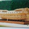
This week I got some work done on the hull despite the snow.
The wooden plates of the upper hull have been cut and bent to the required shapes. The portion from the stern to the end of the waist is fairly flat, with a consistent 13 degree tumblehome. It was cut, fitted to the rabbet cut into the solid lower hull, and screwed in place. Temporary support blocks were fitted to the inside face which also support the dummy quarterdeck that you can see in the photos. The transom piece has been cut and temporarily fitted in place as well.
The bow section is much more complex. In place of the open bow deck with a flat beakhead bulkhead, the ship had a closed bow. At the waist it has the 13 degree tumblehome, but at the cathead it actually has an outward flare as if it were still open. Then when it comes around to the stem it is vertical. To accommodate these requirements, the foredeck corners are bumped out, making it less rounded and the deck overhangs the lower hull.
I derived the shape of the quarterdeck from the plans and cut a dummy deck. This was mounted at the correct height on a sturdy block and screwed into the solid lower hull on the centerline. Rough patterns were cut from cardstock and transferred to ¼” basswood, which was cut oversize at the top. Multiple dados 3/16” deep were cut across the pieces, closer together at the tight bend at the corner. The pieces were wet for an hour in a bucket of water, then forced into shape in the hull rabbet and against the dummy foredeck. They were screwed in place and the top line marked out above the foredeck. The pieces were removed and trimmed, then reinstalled and left to dry.
This is where you see it in the photos, with a dummy stem piece in place. Although I have never used this method of both kerf and wet bending together in a model hull, it seems to be working out pretty well.
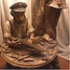
Meanwhile, I continued with some of the deck pieces that will be needed. Here is the bench that sits on the quarterdeck for the captain’s convenience. I’ve never seen this before, but Budriot has it on the plans. If anyone has seen such a fitting, I would be very interested.
Here are his drawings.
And here is how the completed bench looks, with some of the components. The primary wood is birch, with cherry veneer for the accent work and arms.
The arms were built up of four layers of veneer stacked vertically. The outer layers of the horizontal pieces for the arm are sandwiched around two vertical pieces for the post. On the right is the arm piece shaped oversize to the desired curve. On the left it has been trimmed to shape.
Here is the first one completed from another angle.
And here are the finished pair with my scale figures for comparison.
I also set up for the four ladders which will connect the gun deck at the waist with the gangways between the quarterdeck and foredeck. They have only four treads but are wider at the base than at the top.
As you can see in the photo, my ladder technique is to make a long box from which separate ladders can be parted off individually. Two matching rectangular pieces for the stringers have dados cut across the grain. A web of veneer sheet woods are fit into these slots for the treads. The grain runs across from stringer to stringer.
Sorry, this enlargement did not come out too well, but you can see how the dados are cut halfway through the stringer material.
The ladder block was set up so everything was square or, rather, symmetrical until the glue hardened. A ladder was parted off on the band saw at the calculated angle, cleaned up, and finished. This angle might not be right, so I only made one to test. Whatever the ultimate angle, the rest of the block should be enough for at least the four needed for the first model.
I will need a pair of longer ladders from the quarterdeck up to the poop deck on top of the captain’s cabin, and a wider one from the quarterdeck companionway down to the gun deck. They will be made in much the same way.
The companionway itself will be next.
Be well
Dan
-
 shipmodel got a reaction from CaptainSteve in Licorne by mtaylor - 3/16" scale - POF - TERMINATED LOG
Mark -
I got to your log from your response to my question on the log of the QAR. Like all logs when I first find them, I started on page 1 and read forward to the current pages. I was very impressed with all the good work that went into the frames and interior deck details. I commisserated with all the others when you cut your fingers, and cheered, quietly, when you solved the knotty construction problems of the large pumps and the spiled planking.
So I was shocked to read on page 32 that you decided to abandon the model. So much great work. I know that it must have been a difficult decision, but if it is right for you, then it is all for the best. I hope you can save a lot of your detail work and sub-assemblies.
Best of success with Licorne v.2. Charting your progress from the Constellation and cross-section models to here, I am sure that it will be up to your high standards. I look forward to much pleasurable reading as she rises from the building board.
Dan
-
 shipmodel got a reaction from mij in Queen Anne's Revenge 1710 by shipmodel - FINISHED - 1/36 scale
Thanks, Vic. Nicely stated, not understated at all. Thanks too for the likes.
This week I got some work done on the hull despite the snow.
The wooden plates of the upper hull have been cut and bent to the required shapes. The portion from the stern to the end of the waist is fairly flat, with a consistent 13 degree tumblehome. It was cut, fitted to the rabbet cut into the solid lower hull, and screwed in place. Temporary support blocks were fitted to the inside face which also support the dummy quarterdeck that you can see in the photos. The transom piece has been cut and temporarily fitted in place as well.
The bow section is much more complex. In place of the open bow deck with a flat beakhead bulkhead, the ship had a closed bow. At the waist it has the 13 degree tumblehome, but at the cathead it actually has an outward flare as if it were still open. Then when it comes around to the stem it is vertical. To accommodate these requirements, the foredeck corners are bumped out, making it less rounded and the deck overhangs the lower hull.
I derived the shape of the quarterdeck from the plans and cut a dummy deck. This was mounted at the correct height on a sturdy block and screwed into the solid lower hull on the centerline. Rough patterns were cut from cardstock and transferred to ¼” basswood, which was cut oversize at the top. Multiple dados 3/16” deep were cut across the pieces, closer together at the tight bend at the corner. The pieces were wet for an hour in a bucket of water, then forced into shape in the hull rabbet and against the dummy foredeck. They were screwed in place and the top line marked out above the foredeck. The pieces were removed and trimmed, then reinstalled and left to dry.
This is where you see it in the photos, with a dummy stem piece in place. Although I have never used this method of both kerf and wet bending together in a model hull, it seems to be working out pretty well.
Meanwhile, I continued with some of the deck pieces that will be needed. Here is the bench that sits on the quarterdeck for the captain’s convenience. I’ve never seen this before, but Budriot has it on the plans. If anyone has seen such a fitting, I would be very interested.
Here are his drawings.
And here is how the completed bench looks, with some of the components. The primary wood is birch, with cherry veneer for the accent work and arms.
The arms were built up of four layers of veneer stacked vertically. The outer layers of the horizontal pieces for the arm are sandwiched around two vertical pieces for the post. On the right is the arm piece shaped oversize to the desired curve. On the left it has been trimmed to shape.
Here is the first one completed from another angle.
And here are the finished pair with my scale figures for comparison.
I also set up for the four ladders which will connect the gun deck at the waist with the gangways between the quarterdeck and foredeck. They have only four treads but are wider at the base than at the top.
As you can see in the photo, my ladder technique is to make a long box from which separate ladders can be parted off individually. Two matching rectangular pieces for the stringers have dados cut across the grain. A web of veneer sheet woods are fit into these slots for the treads. The grain runs across from stringer to stringer.
Sorry, this enlargement did not come out too well, but you can see how the dados are cut halfway through the stringer material.
The ladder block was set up so everything was square or, rather, symmetrical until the glue hardened. A ladder was parted off on the band saw at the calculated angle, cleaned up, and finished. This angle might not be right, so I only made one to test. Whatever the ultimate angle, the rest of the block should be enough for at least the four needed for the first model.
I will need a pair of longer ladders from the quarterdeck up to the poop deck on top of the captain’s cabin, and a wider one from the quarterdeck companionway down to the gun deck. They will be made in much the same way.
The companionway itself will be next.
Be well
Dan
-
shipmodel got a reaction from dvm27 in Queen Anne's Revenge 1710 by shipmodel - FINISHED - 1/36 scale
Thanks, Vic. Nicely stated, not understated at all. Thanks too for the likes.
This week I got some work done on the hull despite the snow.
The wooden plates of the upper hull have been cut and bent to the required shapes. The portion from the stern to the end of the waist is fairly flat, with a consistent 13 degree tumblehome. It was cut, fitted to the rabbet cut into the solid lower hull, and screwed in place. Temporary support blocks were fitted to the inside face which also support the dummy quarterdeck that you can see in the photos. The transom piece has been cut and temporarily fitted in place as well.
The bow section is much more complex. In place of the open bow deck with a flat beakhead bulkhead, the ship had a closed bow. At the waist it has the 13 degree tumblehome, but at the cathead it actually has an outward flare as if it were still open. Then when it comes around to the stem it is vertical. To accommodate these requirements, the foredeck corners are bumped out, making it less rounded and the deck overhangs the lower hull.
I derived the shape of the quarterdeck from the plans and cut a dummy deck. This was mounted at the correct height on a sturdy block and screwed into the solid lower hull on the centerline. Rough patterns were cut from cardstock and transferred to ¼” basswood, which was cut oversize at the top. Multiple dados 3/16” deep were cut across the pieces, closer together at the tight bend at the corner. The pieces were wet for an hour in a bucket of water, then forced into shape in the hull rabbet and against the dummy foredeck. They were screwed in place and the top line marked out above the foredeck. The pieces were removed and trimmed, then reinstalled and left to dry.
This is where you see it in the photos, with a dummy stem piece in place. Although I have never used this method of both kerf and wet bending together in a model hull, it seems to be working out pretty well.
Meanwhile, I continued with some of the deck pieces that will be needed. Here is the bench that sits on the quarterdeck for the captain’s convenience. I’ve never seen this before, but Budriot has it on the plans. If anyone has seen such a fitting, I would be very interested.
Here are his drawings.
And here is how the completed bench looks, with some of the components. The primary wood is birch, with cherry veneer for the accent work and arms.
The arms were built up of four layers of veneer stacked vertically. The outer layers of the horizontal pieces for the arm are sandwiched around two vertical pieces for the post. On the right is the arm piece shaped oversize to the desired curve. On the left it has been trimmed to shape.
Here is the first one completed from another angle.
And here are the finished pair with my scale figures for comparison.
I also set up for the four ladders which will connect the gun deck at the waist with the gangways between the quarterdeck and foredeck. They have only four treads but are wider at the base than at the top.
As you can see in the photo, my ladder technique is to make a long box from which separate ladders can be parted off individually. Two matching rectangular pieces for the stringers have dados cut across the grain. A web of veneer sheet woods are fit into these slots for the treads. The grain runs across from stringer to stringer.
Sorry, this enlargement did not come out too well, but you can see how the dados are cut halfway through the stringer material.
The ladder block was set up so everything was square or, rather, symmetrical until the glue hardened. A ladder was parted off on the band saw at the calculated angle, cleaned up, and finished. This angle might not be right, so I only made one to test. Whatever the ultimate angle, the rest of the block should be enough for at least the four needed for the first model.
I will need a pair of longer ladders from the quarterdeck up to the poop deck on top of the captain’s cabin, and a wider one from the quarterdeck companionway down to the gun deck. They will be made in much the same way.
The companionway itself will be next.
Be well
Dan
-
 shipmodel got a reaction from CiscoH in Queen Anne's Revenge 1710 by shipmodel - FINISHED - 1/36 scale
Hello again –
I got some time during the football games to write up the next installment. I hope you enjoy it.
With the grating sheets made, I made the coamings. My method here also relies on the table saw and uses no measuring with a ruler. This time it is based on the specific grating to be framed. I make the coaming to fit the grating rather than the other way around. I get a much tighter fit that way.
Here is a piece of grating that has been cut from a sheet. The edges have been sanded flush and it has received a first finish coat to protect it from any glue stains. It looks square, but it is slightly longer than it is wide.
As mentioned, the grating material is poplar. For contrast I selected cherry for the coaming and cut stock 1/8” x ¼”. Four pieces of coaming stock were cut longer than each side of the grating piece. They will be joined with half lap joints at the corners.
The table saw blade height is set so cuts made from the top and bottom of the coaming stock just meet in the middle.
One end of each piece has a half lap cut into it. The length does not matter as long as it is longer than the thickness of the coaming stock. First, the shoulder was cut using the rip fence as a depth stop.
Then the lap was made by making multiple passes moving away from the fence to nibble away the unwanted wood.
A spacer strip was located that was wider but shallower than the lap that was cut.
Using the spacer and the grating piece the fence was set for the shorter sides.
A sacrificial stick supports the coaming piece as the shoulder for the second half lap is cut.
The coaming piece was turned around and the unwanted wood from the second lap was nibbled away.
The matching short piece was done, then the saw was reset and the longer pieces were done in the same manner.
Using the grating piece itself to hold the pieces square, they were test fit, adjusted as needed, assembled and glued. When the glue was dry, support pieces were glued to the inside edges. Doing only two sides is enough. If you want the grating to be removable just make sure that the supports are glued only to the coaming. Here I have glued the grating in place permanently.
The corners were trimmed, the piece was turned over and sanded smooth, and all edges and corners were eased. The bottom edges are left raw and will be sanded to the curve of the deck when installed. The piece was finished with matte varnish.
And here is the set of three for one of the QAR models. In the insert the lap joint is clearly visible. The joints were also treenailed for strength. Two diagonal corners of each coaming were drilled but not filled. During assembly longer treenails will go through them and into the deck for security. A length of treenail stock is packed with the set ready for final assembly.
As you can tell from the brevity of the text, this all goes quite quickly with a some practice. All of the work making the six hatches and gratings took only a little more than a day. Doing the photographing and writing these build log entries took longer.
I hope that this was instructive and provides another technique to add to your tool box.
Be well
Dan
-
 shipmodel got a reaction from popash42 in Queen Anne's Revenge 1710 by shipmodel - FINISHED - 1/36 scale
Hi all, and thanks for the comments and likes.
The next set of independent pieces to be made were the three hatches with gratings. One two-part one goes on the quarterdeck, while the other two go on the gun deck under the boat in the waist. My method for making gratings is a bit unusual in that it there is little or no measuring done with a ruler or calipers. Everything is done relative to the thickness of the saw blade that is used. I developed this method because I only have a Preac saw. A milling machine might make the whole process easier, but I work with what I have.
The first thing is to set up the saw to make square section sticks of wood whose dimension will be about 2 inches in the scale being used. This then has to match the thickness of a saw blade that you have. For the small grating I used a slitting saw blade that was 0.032” thick.
To set the saw I sandwiched that blade between a second blade and the rip fence. The fence is snugged up and locked down. The cutting blade does not have to be the same thickness, although in this case it was since I have two blades of that same thickness.
[These first nine photos are in black and white because they are taken from another presentation on making much smaller gratings].
Several sticks 0.032” square were cut from a sheet of hardwood. Only a few are needed. Then the blade that matches the sticks is mounted in the saw, if it is not already there. Two of the sticks are sandwiched between the blade and the fence which is snugged tight and locked down.
One stick is removed and a short section of the other is held firmly against the fence and tacked in place with extra thin cyano. Care is taken to see that the fence is not glued to the table.
The fence is removed, leaving a guide strip parallel to the blade and one blade thickness to the right.
A rectangular piece of hardwood sheet is selected and held against the guide strip and the miter guage. The blade height is set up to cut just a tiny bit deeper than halfway through the sheet.
The wood is run over the blade, cutting a channel one blade thickness from the end.
The wood is flipped over and the slot that was just cut is placed on top of the guide strip.
The wood is run through again, cutting a second channel two thicknesses to the left of the first channel.
The balance of the sheet is cut in the same way, making a series of channels parallel to each other and spaced two blade widths apart.
Here is the grating sheet for the QAR. At my scale I needed sticks and channels that were about 0.055”. I took one of the 0.032” blades and stacked it together with a 0.023” blade, making a 0.055” dado blade.
Actually, for the small grating I used Portia Takakjian’s technique. This involves cutting lots of square sticks as well as cutting cross channels across the first ones. The cross channels are filled with the sticks and everything is glued together. When dry the solid back of the sheet is ground off with a sanding drum. This works well for a small grating, but the wider blade did not cut as cleanly so I kept getting tearout. Also, I needed more than 25 square inches of grating and did not look forward to grinding off so much wood.
Instead, I removed the guide strip and set the saw to cut 0.55” using the blades as spacers again. Strips were parted off the sheet until the material was used up. I call them toothed strips for obvious reasons.
Three quarters of the toothed strips were cut into thirds and interlocked with the remaining long strips.
This created a grating sheet about 2 ½ by 7 ½ inches. This was only enough to make the gratings for one of the models, so a second grating sheet was made in the same way.
From the sheets I cut out sections for the grating sizes that I needed, sanded the edges flush and gave them a coat of slightly darkened matte finish to protect them from glue stains when the coamings get built around them.
Overall, this method worked well for me, and I will try it in smaller scales in the future. A tip of the hat to Charlie Files, inventor of the Preac, wherever you are.
I will have the log of making the coamings in a few days. Until then, be well.
Dan
-
 shipmodel got a reaction from aykutansin in Queen Anne's Revenge 1710 by shipmodel - FINISHED - 1/36 scale
Thanks, Vic. Nicely stated, not understated at all. Thanks too for the likes.
This week I got some work done on the hull despite the snow.
The wooden plates of the upper hull have been cut and bent to the required shapes. The portion from the stern to the end of the waist is fairly flat, with a consistent 13 degree tumblehome. It was cut, fitted to the rabbet cut into the solid lower hull, and screwed in place. Temporary support blocks were fitted to the inside face which also support the dummy quarterdeck that you can see in the photos. The transom piece has been cut and temporarily fitted in place as well.
The bow section is much more complex. In place of the open bow deck with a flat beakhead bulkhead, the ship had a closed bow. At the waist it has the 13 degree tumblehome, but at the cathead it actually has an outward flare as if it were still open. Then when it comes around to the stem it is vertical. To accommodate these requirements, the foredeck corners are bumped out, making it less rounded and the deck overhangs the lower hull.
I derived the shape of the quarterdeck from the plans and cut a dummy deck. This was mounted at the correct height on a sturdy block and screwed into the solid lower hull on the centerline. Rough patterns were cut from cardstock and transferred to ¼” basswood, which was cut oversize at the top. Multiple dados 3/16” deep were cut across the pieces, closer together at the tight bend at the corner. The pieces were wet for an hour in a bucket of water, then forced into shape in the hull rabbet and against the dummy foredeck. They were screwed in place and the top line marked out above the foredeck. The pieces were removed and trimmed, then reinstalled and left to dry.
This is where you see it in the photos, with a dummy stem piece in place. Although I have never used this method of both kerf and wet bending together in a model hull, it seems to be working out pretty well.
Meanwhile, I continued with some of the deck pieces that will be needed. Here is the bench that sits on the quarterdeck for the captain’s convenience. I’ve never seen this before, but Budriot has it on the plans. If anyone has seen such a fitting, I would be very interested.
Here are his drawings.
And here is how the completed bench looks, with some of the components. The primary wood is birch, with cherry veneer for the accent work and arms.
The arms were built up of four layers of veneer stacked vertically. The outer layers of the horizontal pieces for the arm are sandwiched around two vertical pieces for the post. On the right is the arm piece shaped oversize to the desired curve. On the left it has been trimmed to shape.
Here is the first one completed from another angle.
And here are the finished pair with my scale figures for comparison.
I also set up for the four ladders which will connect the gun deck at the waist with the gangways between the quarterdeck and foredeck. They have only four treads but are wider at the base than at the top.
As you can see in the photo, my ladder technique is to make a long box from which separate ladders can be parted off individually. Two matching rectangular pieces for the stringers have dados cut across the grain. A web of veneer sheet woods are fit into these slots for the treads. The grain runs across from stringer to stringer.
Sorry, this enlargement did not come out too well, but you can see how the dados are cut halfway through the stringer material.
The ladder block was set up so everything was square or, rather, symmetrical until the glue hardened. A ladder was parted off on the band saw at the calculated angle, cleaned up, and finished. This angle might not be right, so I only made one to test. Whatever the ultimate angle, the rest of the block should be enough for at least the four needed for the first model.
I will need a pair of longer ladders from the quarterdeck up to the poop deck on top of the captain’s cabin, and a wider one from the quarterdeck companionway down to the gun deck. They will be made in much the same way.
The companionway itself will be next.
Be well
Dan
-
shipmodel got a reaction from Q A's Revenge in Queen Anne's Revenge 1710 by shipmodel - FINISHED - 1/36 scale
Thanks, Vic. Nicely stated, not understated at all. Thanks too for the likes.
This week I got some work done on the hull despite the snow.
The wooden plates of the upper hull have been cut and bent to the required shapes. The portion from the stern to the end of the waist is fairly flat, with a consistent 13 degree tumblehome. It was cut, fitted to the rabbet cut into the solid lower hull, and screwed in place. Temporary support blocks were fitted to the inside face which also support the dummy quarterdeck that you can see in the photos. The transom piece has been cut and temporarily fitted in place as well.
The bow section is much more complex. In place of the open bow deck with a flat beakhead bulkhead, the ship had a closed bow. At the waist it has the 13 degree tumblehome, but at the cathead it actually has an outward flare as if it were still open. Then when it comes around to the stem it is vertical. To accommodate these requirements, the foredeck corners are bumped out, making it less rounded and the deck overhangs the lower hull.
I derived the shape of the quarterdeck from the plans and cut a dummy deck. This was mounted at the correct height on a sturdy block and screwed into the solid lower hull on the centerline. Rough patterns were cut from cardstock and transferred to ¼” basswood, which was cut oversize at the top. Multiple dados 3/16” deep were cut across the pieces, closer together at the tight bend at the corner. The pieces were wet for an hour in a bucket of water, then forced into shape in the hull rabbet and against the dummy foredeck. They were screwed in place and the top line marked out above the foredeck. The pieces were removed and trimmed, then reinstalled and left to dry.
This is where you see it in the photos, with a dummy stem piece in place. Although I have never used this method of both kerf and wet bending together in a model hull, it seems to be working out pretty well.
Meanwhile, I continued with some of the deck pieces that will be needed. Here is the bench that sits on the quarterdeck for the captain’s convenience. I’ve never seen this before, but Budriot has it on the plans. If anyone has seen such a fitting, I would be very interested.
Here are his drawings.
And here is how the completed bench looks, with some of the components. The primary wood is birch, with cherry veneer for the accent work and arms.
The arms were built up of four layers of veneer stacked vertically. The outer layers of the horizontal pieces for the arm are sandwiched around two vertical pieces for the post. On the right is the arm piece shaped oversize to the desired curve. On the left it has been trimmed to shape.
Here is the first one completed from another angle.
And here are the finished pair with my scale figures for comparison.
I also set up for the four ladders which will connect the gun deck at the waist with the gangways between the quarterdeck and foredeck. They have only four treads but are wider at the base than at the top.
As you can see in the photo, my ladder technique is to make a long box from which separate ladders can be parted off individually. Two matching rectangular pieces for the stringers have dados cut across the grain. A web of veneer sheet woods are fit into these slots for the treads. The grain runs across from stringer to stringer.
Sorry, this enlargement did not come out too well, but you can see how the dados are cut halfway through the stringer material.
The ladder block was set up so everything was square or, rather, symmetrical until the glue hardened. A ladder was parted off on the band saw at the calculated angle, cleaned up, and finished. This angle might not be right, so I only made one to test. Whatever the ultimate angle, the rest of the block should be enough for at least the four needed for the first model.
I will need a pair of longer ladders from the quarterdeck up to the poop deck on top of the captain’s cabin, and a wider one from the quarterdeck companionway down to the gun deck. They will be made in much the same way.
The companionway itself will be next.
Be well
Dan
-
 shipmodel got a reaction from dgbot in Queen Anne's Revenge 1710 by shipmodel - FINISHED - 1/36 scale
Thanks, Vic. Nicely stated, not understated at all. Thanks too for the likes.
This week I got some work done on the hull despite the snow.
The wooden plates of the upper hull have been cut and bent to the required shapes. The portion from the stern to the end of the waist is fairly flat, with a consistent 13 degree tumblehome. It was cut, fitted to the rabbet cut into the solid lower hull, and screwed in place. Temporary support blocks were fitted to the inside face which also support the dummy quarterdeck that you can see in the photos. The transom piece has been cut and temporarily fitted in place as well.
The bow section is much more complex. In place of the open bow deck with a flat beakhead bulkhead, the ship had a closed bow. At the waist it has the 13 degree tumblehome, but at the cathead it actually has an outward flare as if it were still open. Then when it comes around to the stem it is vertical. To accommodate these requirements, the foredeck corners are bumped out, making it less rounded and the deck overhangs the lower hull.
I derived the shape of the quarterdeck from the plans and cut a dummy deck. This was mounted at the correct height on a sturdy block and screwed into the solid lower hull on the centerline. Rough patterns were cut from cardstock and transferred to ¼” basswood, which was cut oversize at the top. Multiple dados 3/16” deep were cut across the pieces, closer together at the tight bend at the corner. The pieces were wet for an hour in a bucket of water, then forced into shape in the hull rabbet and against the dummy foredeck. They were screwed in place and the top line marked out above the foredeck. The pieces were removed and trimmed, then reinstalled and left to dry.
This is where you see it in the photos, with a dummy stem piece in place. Although I have never used this method of both kerf and wet bending together in a model hull, it seems to be working out pretty well.
Meanwhile, I continued with some of the deck pieces that will be needed. Here is the bench that sits on the quarterdeck for the captain’s convenience. I’ve never seen this before, but Budriot has it on the plans. If anyone has seen such a fitting, I would be very interested.
Here are his drawings.
And here is how the completed bench looks, with some of the components. The primary wood is birch, with cherry veneer for the accent work and arms.
The arms were built up of four layers of veneer stacked vertically. The outer layers of the horizontal pieces for the arm are sandwiched around two vertical pieces for the post. On the right is the arm piece shaped oversize to the desired curve. On the left it has been trimmed to shape.
Here is the first one completed from another angle.
And here are the finished pair with my scale figures for comparison.
I also set up for the four ladders which will connect the gun deck at the waist with the gangways between the quarterdeck and foredeck. They have only four treads but are wider at the base than at the top.
As you can see in the photo, my ladder technique is to make a long box from which separate ladders can be parted off individually. Two matching rectangular pieces for the stringers have dados cut across the grain. A web of veneer sheet woods are fit into these slots for the treads. The grain runs across from stringer to stringer.
Sorry, this enlargement did not come out too well, but you can see how the dados are cut halfway through the stringer material.
The ladder block was set up so everything was square or, rather, symmetrical until the glue hardened. A ladder was parted off on the band saw at the calculated angle, cleaned up, and finished. This angle might not be right, so I only made one to test. Whatever the ultimate angle, the rest of the block should be enough for at least the four needed for the first model.
I will need a pair of longer ladders from the quarterdeck up to the poop deck on top of the captain’s cabin, and a wider one from the quarterdeck companionway down to the gun deck. They will be made in much the same way.
The companionway itself will be next.
Be well
Dan
-
 shipmodel got a reaction from WackoWolf in Queen Anne's Revenge 1710 by shipmodel - FINISHED - 1/36 scale
Thanks, Vic. Nicely stated, not understated at all. Thanks too for the likes.
This week I got some work done on the hull despite the snow.
The wooden plates of the upper hull have been cut and bent to the required shapes. The portion from the stern to the end of the waist is fairly flat, with a consistent 13 degree tumblehome. It was cut, fitted to the rabbet cut into the solid lower hull, and screwed in place. Temporary support blocks were fitted to the inside face which also support the dummy quarterdeck that you can see in the photos. The transom piece has been cut and temporarily fitted in place as well.
The bow section is much more complex. In place of the open bow deck with a flat beakhead bulkhead, the ship had a closed bow. At the waist it has the 13 degree tumblehome, but at the cathead it actually has an outward flare as if it were still open. Then when it comes around to the stem it is vertical. To accommodate these requirements, the foredeck corners are bumped out, making it less rounded and the deck overhangs the lower hull.
I derived the shape of the quarterdeck from the plans and cut a dummy deck. This was mounted at the correct height on a sturdy block and screwed into the solid lower hull on the centerline. Rough patterns were cut from cardstock and transferred to ¼” basswood, which was cut oversize at the top. Multiple dados 3/16” deep were cut across the pieces, closer together at the tight bend at the corner. The pieces were wet for an hour in a bucket of water, then forced into shape in the hull rabbet and against the dummy foredeck. They were screwed in place and the top line marked out above the foredeck. The pieces were removed and trimmed, then reinstalled and left to dry.
This is where you see it in the photos, with a dummy stem piece in place. Although I have never used this method of both kerf and wet bending together in a model hull, it seems to be working out pretty well.
Meanwhile, I continued with some of the deck pieces that will be needed. Here is the bench that sits on the quarterdeck for the captain’s convenience. I’ve never seen this before, but Budriot has it on the plans. If anyone has seen such a fitting, I would be very interested.
Here are his drawings.
And here is how the completed bench looks, with some of the components. The primary wood is birch, with cherry veneer for the accent work and arms.
The arms were built up of four layers of veneer stacked vertically. The outer layers of the horizontal pieces for the arm are sandwiched around two vertical pieces for the post. On the right is the arm piece shaped oversize to the desired curve. On the left it has been trimmed to shape.
Here is the first one completed from another angle.
And here are the finished pair with my scale figures for comparison.
I also set up for the four ladders which will connect the gun deck at the waist with the gangways between the quarterdeck and foredeck. They have only four treads but are wider at the base than at the top.
As you can see in the photo, my ladder technique is to make a long box from which separate ladders can be parted off individually. Two matching rectangular pieces for the stringers have dados cut across the grain. A web of veneer sheet woods are fit into these slots for the treads. The grain runs across from stringer to stringer.
Sorry, this enlargement did not come out too well, but you can see how the dados are cut halfway through the stringer material.
The ladder block was set up so everything was square or, rather, symmetrical until the glue hardened. A ladder was parted off on the band saw at the calculated angle, cleaned up, and finished. This angle might not be right, so I only made one to test. Whatever the ultimate angle, the rest of the block should be enough for at least the four needed for the first model.
I will need a pair of longer ladders from the quarterdeck up to the poop deck on top of the captain’s cabin, and a wider one from the quarterdeck companionway down to the gun deck. They will be made in much the same way.
The companionway itself will be next.
Be well
Dan
-
shipmodel got a reaction from popash42 in Queen Anne's Revenge 1710 by shipmodel - FINISHED - 1/36 scale
Hello again –
I got some time during the football games to write up the next installment. I hope you enjoy it.
With the grating sheets made, I made the coamings. My method here also relies on the table saw and uses no measuring with a ruler. This time it is based on the specific grating to be framed. I make the coaming to fit the grating rather than the other way around. I get a much tighter fit that way.
Here is a piece of grating that has been cut from a sheet. The edges have been sanded flush and it has received a first finish coat to protect it from any glue stains. It looks square, but it is slightly longer than it is wide.
As mentioned, the grating material is poplar. For contrast I selected cherry for the coaming and cut stock 1/8” x ¼”. Four pieces of coaming stock were cut longer than each side of the grating piece. They will be joined with half lap joints at the corners.
The table saw blade height is set so cuts made from the top and bottom of the coaming stock just meet in the middle.
One end of each piece has a half lap cut into it. The length does not matter as long as it is longer than the thickness of the coaming stock. First, the shoulder was cut using the rip fence as a depth stop.
Then the lap was made by making multiple passes moving away from the fence to nibble away the unwanted wood.
A spacer strip was located that was wider but shallower than the lap that was cut.
Using the spacer and the grating piece the fence was set for the shorter sides.
A sacrificial stick supports the coaming piece as the shoulder for the second half lap is cut.
The coaming piece was turned around and the unwanted wood from the second lap was nibbled away.
The matching short piece was done, then the saw was reset and the longer pieces were done in the same manner.
Using the grating piece itself to hold the pieces square, they were test fit, adjusted as needed, assembled and glued. When the glue was dry, support pieces were glued to the inside edges. Doing only two sides is enough. If you want the grating to be removable just make sure that the supports are glued only to the coaming. Here I have glued the grating in place permanently.
The corners were trimmed, the piece was turned over and sanded smooth, and all edges and corners were eased. The bottom edges are left raw and will be sanded to the curve of the deck when installed. The piece was finished with matte varnish.
And here is the set of three for one of the QAR models. In the insert the lap joint is clearly visible. The joints were also treenailed for strength. Two diagonal corners of each coaming were drilled but not filled. During assembly longer treenails will go through them and into the deck for security. A length of treenail stock is packed with the set ready for final assembly.
As you can tell from the brevity of the text, this all goes quite quickly with a some practice. All of the work making the six hatches and gratings took only a little more than a day. Doing the photographing and writing these build log entries took longer.
I hope that this was instructive and provides another technique to add to your tool box.
Be well
Dan
-
 shipmodel got a reaction from Archi in Queen Anne's Revenge 1710 by shipmodel - FINISHED - 1/36 scale
Hi all, and thanks for the comments and likes.
The next set of independent pieces to be made were the three hatches with gratings. One two-part one goes on the quarterdeck, while the other two go on the gun deck under the boat in the waist. My method for making gratings is a bit unusual in that it there is little or no measuring done with a ruler or calipers. Everything is done relative to the thickness of the saw blade that is used. I developed this method because I only have a Preac saw. A milling machine might make the whole process easier, but I work with what I have.
The first thing is to set up the saw to make square section sticks of wood whose dimension will be about 2 inches in the scale being used. This then has to match the thickness of a saw blade that you have. For the small grating I used a slitting saw blade that was 0.032” thick.
To set the saw I sandwiched that blade between a second blade and the rip fence. The fence is snugged up and locked down. The cutting blade does not have to be the same thickness, although in this case it was since I have two blades of that same thickness.
[These first nine photos are in black and white because they are taken from another presentation on making much smaller gratings].
Several sticks 0.032” square were cut from a sheet of hardwood. Only a few are needed. Then the blade that matches the sticks is mounted in the saw, if it is not already there. Two of the sticks are sandwiched between the blade and the fence which is snugged tight and locked down.
One stick is removed and a short section of the other is held firmly against the fence and tacked in place with extra thin cyano. Care is taken to see that the fence is not glued to the table.
The fence is removed, leaving a guide strip parallel to the blade and one blade thickness to the right.
A rectangular piece of hardwood sheet is selected and held against the guide strip and the miter guage. The blade height is set up to cut just a tiny bit deeper than halfway through the sheet.
The wood is run over the blade, cutting a channel one blade thickness from the end.
The wood is flipped over and the slot that was just cut is placed on top of the guide strip.
The wood is run through again, cutting a second channel two thicknesses to the left of the first channel.
The balance of the sheet is cut in the same way, making a series of channels parallel to each other and spaced two blade widths apart.
Here is the grating sheet for the QAR. At my scale I needed sticks and channels that were about 0.055”. I took one of the 0.032” blades and stacked it together with a 0.023” blade, making a 0.055” dado blade.
Actually, for the small grating I used Portia Takakjian’s technique. This involves cutting lots of square sticks as well as cutting cross channels across the first ones. The cross channels are filled with the sticks and everything is glued together. When dry the solid back of the sheet is ground off with a sanding drum. This works well for a small grating, but the wider blade did not cut as cleanly so I kept getting tearout. Also, I needed more than 25 square inches of grating and did not look forward to grinding off so much wood.
Instead, I removed the guide strip and set the saw to cut 0.55” using the blades as spacers again. Strips were parted off the sheet until the material was used up. I call them toothed strips for obvious reasons.
Three quarters of the toothed strips were cut into thirds and interlocked with the remaining long strips.
This created a grating sheet about 2 ½ by 7 ½ inches. This was only enough to make the gratings for one of the models, so a second grating sheet was made in the same way.
From the sheets I cut out sections for the grating sizes that I needed, sanded the edges flush and gave them a coat of slightly darkened matte finish to protect them from glue stains when the coamings get built around them.
Overall, this method worked well for me, and I will try it in smaller scales in the future. A tip of the hat to Charlie Files, inventor of the Preac, wherever you are.
I will have the log of making the coamings in a few days. Until then, be well.
Dan
-
 shipmodel got a reaction from BareHook in Queen Anne's Revenge 1710 by shipmodel - FINISHED - 1/36 scale
Thanks, Vic. Nicely stated, not understated at all. Thanks too for the likes.
This week I got some work done on the hull despite the snow.
The wooden plates of the upper hull have been cut and bent to the required shapes. The portion from the stern to the end of the waist is fairly flat, with a consistent 13 degree tumblehome. It was cut, fitted to the rabbet cut into the solid lower hull, and screwed in place. Temporary support blocks were fitted to the inside face which also support the dummy quarterdeck that you can see in the photos. The transom piece has been cut and temporarily fitted in place as well.
The bow section is much more complex. In place of the open bow deck with a flat beakhead bulkhead, the ship had a closed bow. At the waist it has the 13 degree tumblehome, but at the cathead it actually has an outward flare as if it were still open. Then when it comes around to the stem it is vertical. To accommodate these requirements, the foredeck corners are bumped out, making it less rounded and the deck overhangs the lower hull.
I derived the shape of the quarterdeck from the plans and cut a dummy deck. This was mounted at the correct height on a sturdy block and screwed into the solid lower hull on the centerline. Rough patterns were cut from cardstock and transferred to ¼” basswood, which was cut oversize at the top. Multiple dados 3/16” deep were cut across the pieces, closer together at the tight bend at the corner. The pieces were wet for an hour in a bucket of water, then forced into shape in the hull rabbet and against the dummy foredeck. They were screwed in place and the top line marked out above the foredeck. The pieces were removed and trimmed, then reinstalled and left to dry.
This is where you see it in the photos, with a dummy stem piece in place. Although I have never used this method of both kerf and wet bending together in a model hull, it seems to be working out pretty well.
Meanwhile, I continued with some of the deck pieces that will be needed. Here is the bench that sits on the quarterdeck for the captain’s convenience. I’ve never seen this before, but Budriot has it on the plans. If anyone has seen such a fitting, I would be very interested.
Here are his drawings.
And here is how the completed bench looks, with some of the components. The primary wood is birch, with cherry veneer for the accent work and arms.
The arms were built up of four layers of veneer stacked vertically. The outer layers of the horizontal pieces for the arm are sandwiched around two vertical pieces for the post. On the right is the arm piece shaped oversize to the desired curve. On the left it has been trimmed to shape.
Here is the first one completed from another angle.
And here are the finished pair with my scale figures for comparison.
I also set up for the four ladders which will connect the gun deck at the waist with the gangways between the quarterdeck and foredeck. They have only four treads but are wider at the base than at the top.
As you can see in the photo, my ladder technique is to make a long box from which separate ladders can be parted off individually. Two matching rectangular pieces for the stringers have dados cut across the grain. A web of veneer sheet woods are fit into these slots for the treads. The grain runs across from stringer to stringer.
Sorry, this enlargement did not come out too well, but you can see how the dados are cut halfway through the stringer material.
The ladder block was set up so everything was square or, rather, symmetrical until the glue hardened. A ladder was parted off on the band saw at the calculated angle, cleaned up, and finished. This angle might not be right, so I only made one to test. Whatever the ultimate angle, the rest of the block should be enough for at least the four needed for the first model.
I will need a pair of longer ladders from the quarterdeck up to the poop deck on top of the captain’s cabin, and a wider one from the quarterdeck companionway down to the gun deck. They will be made in much the same way.
The companionway itself will be next.
Be well
Dan
-
 shipmodel got a reaction from tarbrush in Queen Anne's Revenge 1710 by shipmodel - FINISHED - 1/36 scale
Thanks, Vic. Nicely stated, not understated at all. Thanks too for the likes.
This week I got some work done on the hull despite the snow.
The wooden plates of the upper hull have been cut and bent to the required shapes. The portion from the stern to the end of the waist is fairly flat, with a consistent 13 degree tumblehome. It was cut, fitted to the rabbet cut into the solid lower hull, and screwed in place. Temporary support blocks were fitted to the inside face which also support the dummy quarterdeck that you can see in the photos. The transom piece has been cut and temporarily fitted in place as well.
The bow section is much more complex. In place of the open bow deck with a flat beakhead bulkhead, the ship had a closed bow. At the waist it has the 13 degree tumblehome, but at the cathead it actually has an outward flare as if it were still open. Then when it comes around to the stem it is vertical. To accommodate these requirements, the foredeck corners are bumped out, making it less rounded and the deck overhangs the lower hull.
I derived the shape of the quarterdeck from the plans and cut a dummy deck. This was mounted at the correct height on a sturdy block and screwed into the solid lower hull on the centerline. Rough patterns were cut from cardstock and transferred to ¼” basswood, which was cut oversize at the top. Multiple dados 3/16” deep were cut across the pieces, closer together at the tight bend at the corner. The pieces were wet for an hour in a bucket of water, then forced into shape in the hull rabbet and against the dummy foredeck. They were screwed in place and the top line marked out above the foredeck. The pieces were removed and trimmed, then reinstalled and left to dry.
This is where you see it in the photos, with a dummy stem piece in place. Although I have never used this method of both kerf and wet bending together in a model hull, it seems to be working out pretty well.
Meanwhile, I continued with some of the deck pieces that will be needed. Here is the bench that sits on the quarterdeck for the captain’s convenience. I’ve never seen this before, but Budriot has it on the plans. If anyone has seen such a fitting, I would be very interested.
Here are his drawings.
And here is how the completed bench looks, with some of the components. The primary wood is birch, with cherry veneer for the accent work and arms.
The arms were built up of four layers of veneer stacked vertically. The outer layers of the horizontal pieces for the arm are sandwiched around two vertical pieces for the post. On the right is the arm piece shaped oversize to the desired curve. On the left it has been trimmed to shape.
Here is the first one completed from another angle.
And here are the finished pair with my scale figures for comparison.
I also set up for the four ladders which will connect the gun deck at the waist with the gangways between the quarterdeck and foredeck. They have only four treads but are wider at the base than at the top.
As you can see in the photo, my ladder technique is to make a long box from which separate ladders can be parted off individually. Two matching rectangular pieces for the stringers have dados cut across the grain. A web of veneer sheet woods are fit into these slots for the treads. The grain runs across from stringer to stringer.
Sorry, this enlargement did not come out too well, but you can see how the dados are cut halfway through the stringer material.
The ladder block was set up so everything was square or, rather, symmetrical until the glue hardened. A ladder was parted off on the band saw at the calculated angle, cleaned up, and finished. This angle might not be right, so I only made one to test. Whatever the ultimate angle, the rest of the block should be enough for at least the four needed for the first model.
I will need a pair of longer ladders from the quarterdeck up to the poop deck on top of the captain’s cabin, and a wider one from the quarterdeck companionway down to the gun deck. They will be made in much the same way.
The companionway itself will be next.
Be well
Dan
-
 shipmodel got a reaction from aviaamator in Queen Anne's Revenge 1710 by shipmodel - FINISHED - 1/36 scale
Hi all, and thanks for the comments and likes.
The next set of independent pieces to be made were the three hatches with gratings. One two-part one goes on the quarterdeck, while the other two go on the gun deck under the boat in the waist. My method for making gratings is a bit unusual in that it there is little or no measuring done with a ruler or calipers. Everything is done relative to the thickness of the saw blade that is used. I developed this method because I only have a Preac saw. A milling machine might make the whole process easier, but I work with what I have.
The first thing is to set up the saw to make square section sticks of wood whose dimension will be about 2 inches in the scale being used. This then has to match the thickness of a saw blade that you have. For the small grating I used a slitting saw blade that was 0.032” thick.
To set the saw I sandwiched that blade between a second blade and the rip fence. The fence is snugged up and locked down. The cutting blade does not have to be the same thickness, although in this case it was since I have two blades of that same thickness.
[These first nine photos are in black and white because they are taken from another presentation on making much smaller gratings].
Several sticks 0.032” square were cut from a sheet of hardwood. Only a few are needed. Then the blade that matches the sticks is mounted in the saw, if it is not already there. Two of the sticks are sandwiched between the blade and the fence which is snugged tight and locked down.
One stick is removed and a short section of the other is held firmly against the fence and tacked in place with extra thin cyano. Care is taken to see that the fence is not glued to the table.
The fence is removed, leaving a guide strip parallel to the blade and one blade thickness to the right.
A rectangular piece of hardwood sheet is selected and held against the guide strip and the miter guage. The blade height is set up to cut just a tiny bit deeper than halfway through the sheet.
The wood is run over the blade, cutting a channel one blade thickness from the end.
The wood is flipped over and the slot that was just cut is placed on top of the guide strip.
The wood is run through again, cutting a second channel two thicknesses to the left of the first channel.
The balance of the sheet is cut in the same way, making a series of channels parallel to each other and spaced two blade widths apart.
Here is the grating sheet for the QAR. At my scale I needed sticks and channels that were about 0.055”. I took one of the 0.032” blades and stacked it together with a 0.023” blade, making a 0.055” dado blade.
Actually, for the small grating I used Portia Takakjian’s technique. This involves cutting lots of square sticks as well as cutting cross channels across the first ones. The cross channels are filled with the sticks and everything is glued together. When dry the solid back of the sheet is ground off with a sanding drum. This works well for a small grating, but the wider blade did not cut as cleanly so I kept getting tearout. Also, I needed more than 25 square inches of grating and did not look forward to grinding off so much wood.
Instead, I removed the guide strip and set the saw to cut 0.55” using the blades as spacers again. Strips were parted off the sheet until the material was used up. I call them toothed strips for obvious reasons.
Three quarters of the toothed strips were cut into thirds and interlocked with the remaining long strips.
This created a grating sheet about 2 ½ by 7 ½ inches. This was only enough to make the gratings for one of the models, so a second grating sheet was made in the same way.
From the sheets I cut out sections for the grating sizes that I needed, sanded the edges flush and gave them a coat of slightly darkened matte finish to protect them from glue stains when the coamings get built around them.
Overall, this method worked well for me, and I will try it in smaller scales in the future. A tip of the hat to Charlie Files, inventor of the Preac, wherever you are.
I will have the log of making the coamings in a few days. Until then, be well.
Dan