
robert952
-
Posts
922 -
Joined
-
Last visited
Content Type
Profiles
Forums
Gallery
Events
Everything posted by robert952
-
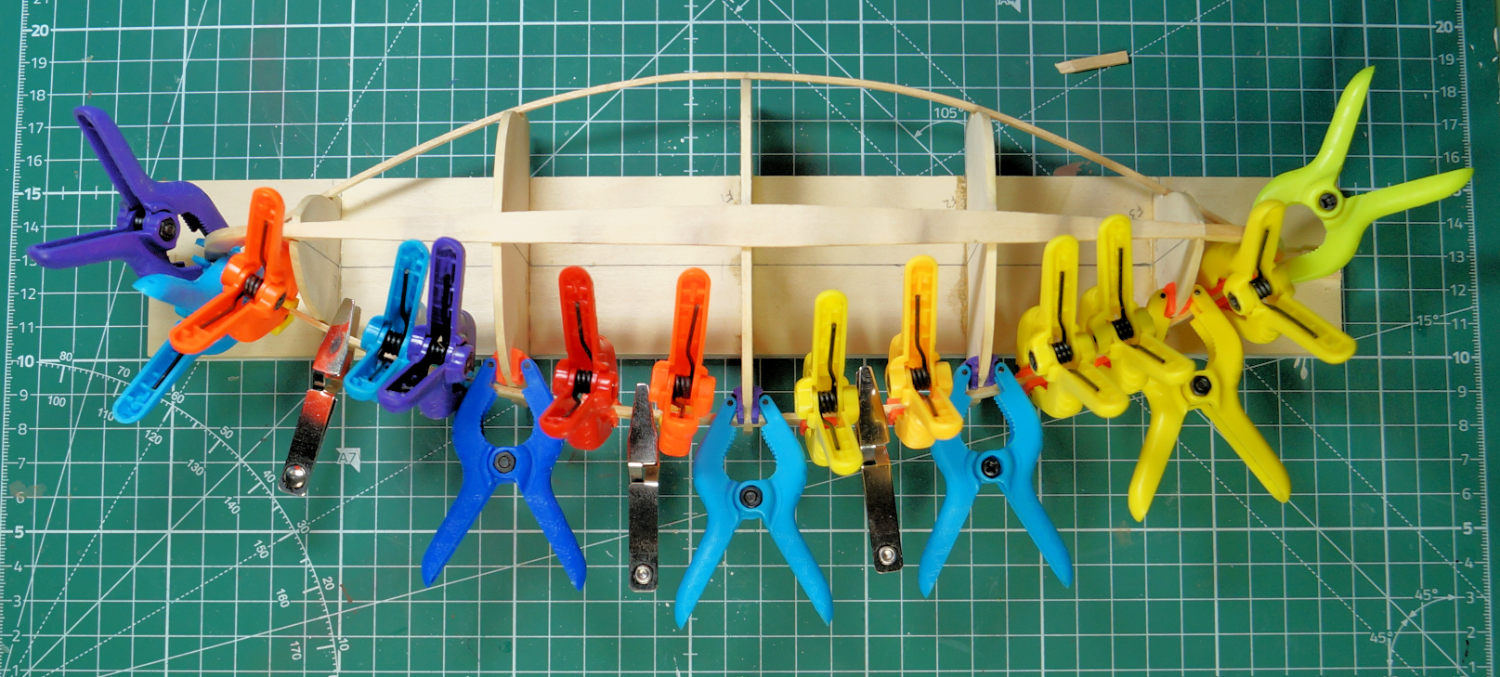
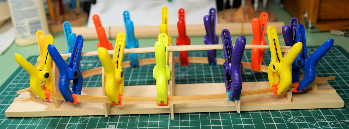
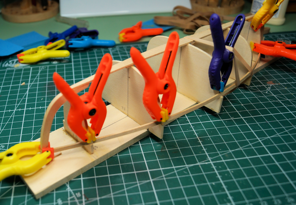
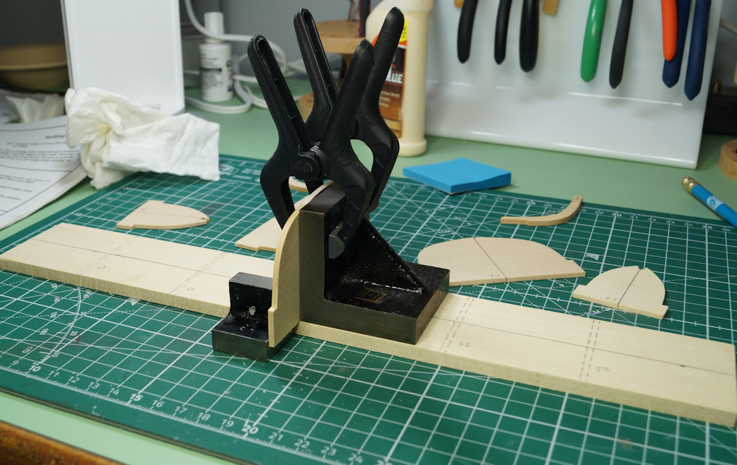
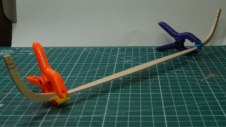
 First two planks assembled. As I said above, I decided to shape the planks around the bulkheads rather than use 'brute force.' The instructions do not discuss any method for soaking the planks before bending. They show the planks pressed into position. I think shaping the wood reduces or even eliminate stress where the planks meet the stem posts. I read various articles and threads on plank bending here (and reviewed a couple of books in my library). Based on what I read, I built a tube to soak the planks. I bought some PVC plumbing parts. My local Home Depot did not have the end caps I wanted, so I used a 'cleanout' connector on a precut piece of PVC pipe. I think this was, as Bob Ross would say, a "happy accident". I used a piece of scrap plywood. I made a square hole for the cleanout nut. I epoxied the assembled tube into the plywood to keep the whole thing stable when in use. A bit of paint to 'dress it up a bit' though the intent is utility over aesthetics. While not as elegant as some of the described pipes for soaking, my tube works well enough. I use the rubber band to hold a paper towel to keep the wood from floating up in the tube. (AND, the tube didn't leak...a big plus over my usual work with plumbing.) While a lot of the MSW threads indicates 10-20 minutes of soaking time, I found I didn't need to soak them that long. I need only a smooth curve, not any hard bends to the wood. After about 5 - 6 minutes of soaking, I could place the wood around the bulkheads and hold them in place while they dried. Here's a shot of the wet wood (slight discoloration seen below) of the second plank being held in place. When the wood dried, the shape held with very little 'force fitting.' I am using wood glue over CA or PVA. As with a lot of discussions, the choice is as much a personal choice as anything. As mentioned in my previous post, I coated the edges of the bulkheads with beeswax. Even with the 'form fit' of the wood pieces, I made sure to secure the planks to each other. Is it possible to use too many clamps? I had some left over and was just wondering. I followed the instruction manual by first attaching one end of the plank to one stem post. I then glued the edges of the planks, clamping them into position as I went. I quickly finished the plank by gluing it to the other stem post. The glue on the the starting end had almost set. I made sure the glue had set and then did the other side of the boat. Here's a couple of images of the first two planks assembled with the glue dry and set. So far, the boards are not sticking to the bulkheads. Hopefully a combination of my being as neat as possible with the glue and using the beeswax. I will have to take care to cut the stems since I modified the strong back a bit. However, I think the final assembled boat will easily come off of the strong back. The next couple of planks will not need much bevel for a good fit. However, as the planks go around to the bilge, the edges have to be beveled for a tight fit. The instructions do not indicate this as part of the process. They indicate to align the planks "so that there is not a step between the adjacent planks." Beveling the planks should make a better fit. Hopefully, beveling will reduce the number of gaps that will need filling.
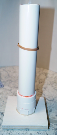

- 44 replies
-
- 6
-

-
- maine peapod
- peapod
- (and 4 more)
-
Very nice looking display stand. I like the proportions and seems a good fit for the model.
-
Climbing aboard to watch this build. Welcome to MSW. Looking good so far.
- 39 replies
-
- 1
-
-
- Lowell Grand Banks Dory
- Model Shipways
- (and 1 more)
-
This is why I like reading these build logs. I had forgotten I had one one of these flexible curves. I looked around and can't find it. So, it may be lost. I can see this as a useful tool for simple curves like on a small boat. Thanks for suggesting this.
- 72 replies
-
- 1
-
-
- Norwegian Sailing Pram
- Model Shipways
- (and 1 more)
-
Not an update per se but something I ran across. I stumbled across @Dan Vadas thread (LINK) and added 'Small' to my topic title. I like the idea. (Should small be a tag, too?)
-
Short answer: Start a new topic in the appropriate 'build logs' sub-forum: View from MSW home page: The title should be in the format of "Name of ship/boat - your user name - manufacturer - scale. Here's the link that may help. Link. Also add tags to help others searching for specific models that have been built or that's a work in process. Terms like the ship's name and maybe manufacturer. Think in terms you would use if you were looking for a particular ship or subject. Hope this helps. Welcome to MSW.
-
Nice looking build. Jumping on the train to follow this.
-
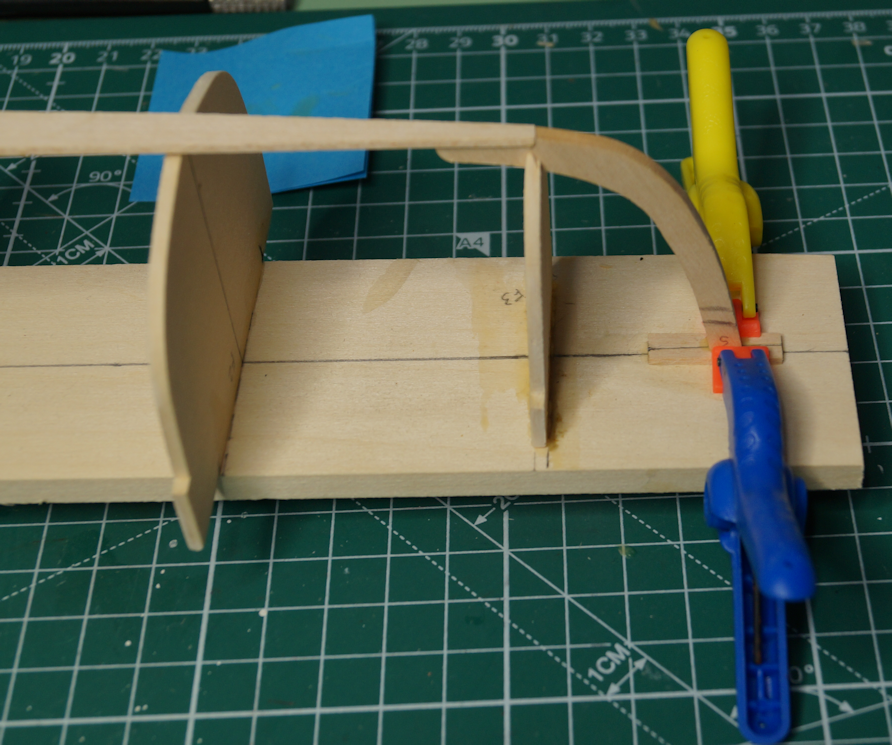
Test Fitting First Plank. I did a test fit of the first plank. From that I found that I want to actually bend the planks into shape. So, it's off to review plank bending techniques. It's not a lot of bend required. I just feel that if the planks fit there's less stress on the shape of the boat at the stem posts. (It's still a double-ender so I haven't determined a bow and stem. That will come as I add the rudder.) A couple of build logs pointed out an issue with the sides of the boat squeezing inward once the boat was removed from the strong back. I will keep in mind that the center bulkhead may have to remain in place. Again, reading some build logs and Dynamite Payson's Boat Modeling with Dynamite Payson, I read suggestions to use bee's wax on the bulkheads' edges to help keep glue off the edges of the bulkheads. That's been applied at this point also.
- 44 replies
-
- 6
-
-
- maine peapod
- peapod
- (and 4 more)
-
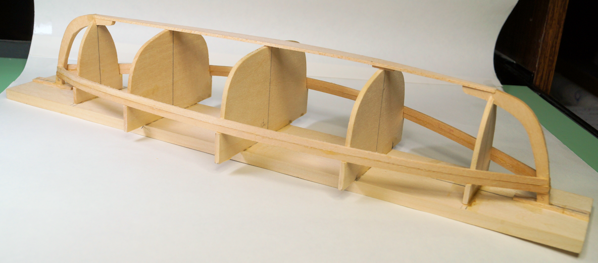
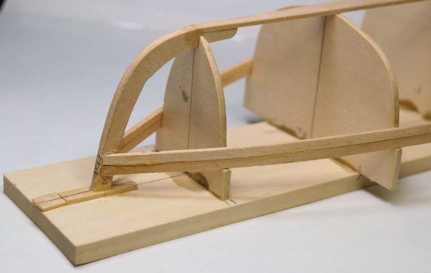
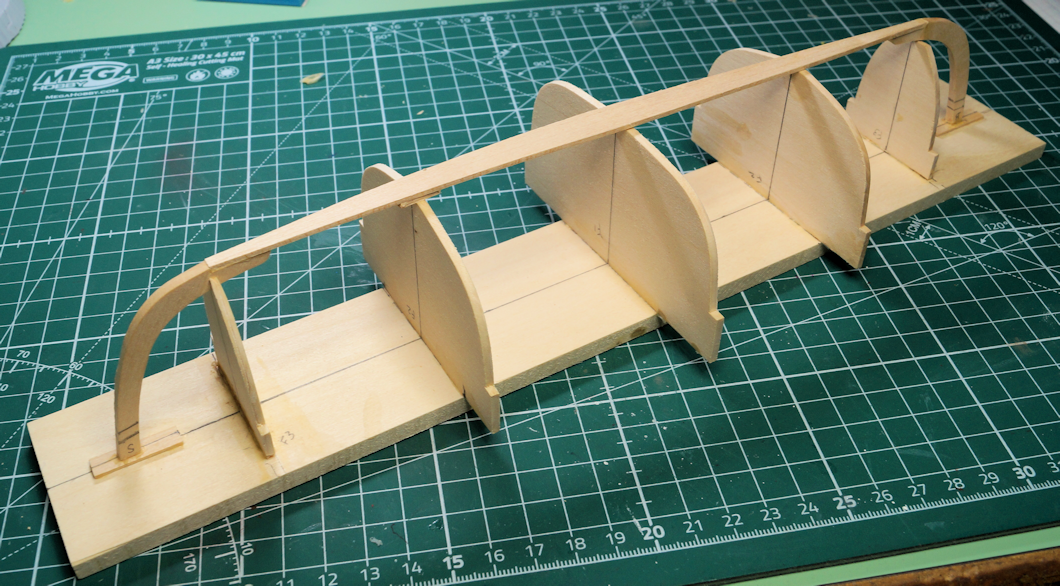
Building the strong back. The boat is built 'upside down' with on a strong back. So, the first steps build this assembly. In my 'research' information, I did not mention part of the research covered build logs here at MSW (and other places). Reading those logs gave me some things to be aware of that I could avoid as well as useful tips and hints. One key point was to be sure the bulkheads are squared and perpendicular. The stem posts and floor board to make what I will call the 'keel frame.' At this point I hadn't marked the ribs and floor boards locations. That's the next step. I had a problem getting the 'keel frame' to attach to the mounting board of the strong back. When I forced the fit I managed to break one of the bulkheads off. So, after repairing that, I went back to review the matter. As I analyzed the problem, I determined two things. The keel frame did not sit on the bulkheads. The keel was bowed when I tried to glue the frame to the mounting board. Additionally, the drawing from Chapelle's book shows an almost flat keel line. So, I wanted to adjust for that. To fix the problem I cut some spacers to place under the bow and stern stem posts. That allows the bottom to be parallel to the ground. I did also have to do an adjustment to the frames to be sure it supported the keel frame as one vertical bulkhead didn't quite lay flat. That completed the strong back assembly. After this picture, I extended those pieces because I will be adding a 3/8" keel to the false keel which rests on the strong back assembly. This addition will allow the keel to extend above the sheer and may serve as a location to attach the rigging.
- 44 replies
-
- 6
-
-
- maine peapod
- peapod
- (and 4 more)
-
Nice job! Rigging looks great. As commented, great job at weathering.
- 31 replies
-
- 2
-
-
- Grand Banks Dory
- Bluejacket Shipcrafters
- (and 1 more)
-
Holding small parts for soldering
robert952 replied to BETAQDAVE's topic in Metal Work, Soldering and Metal Fittings
@druxy yep...there's five hands on this version. The one pictured has strong magnets (rare earth?) and you can place the flex arms anywhere on the plate. I have one of these and one with screw mounted arms in each corner from a similar company prodctu offering. (a similar but different company's product) has 6 holes - one in each corner and holes in center of the long side of the rectangle. The companies also sell arms separately. IMO well worth the money spent. -
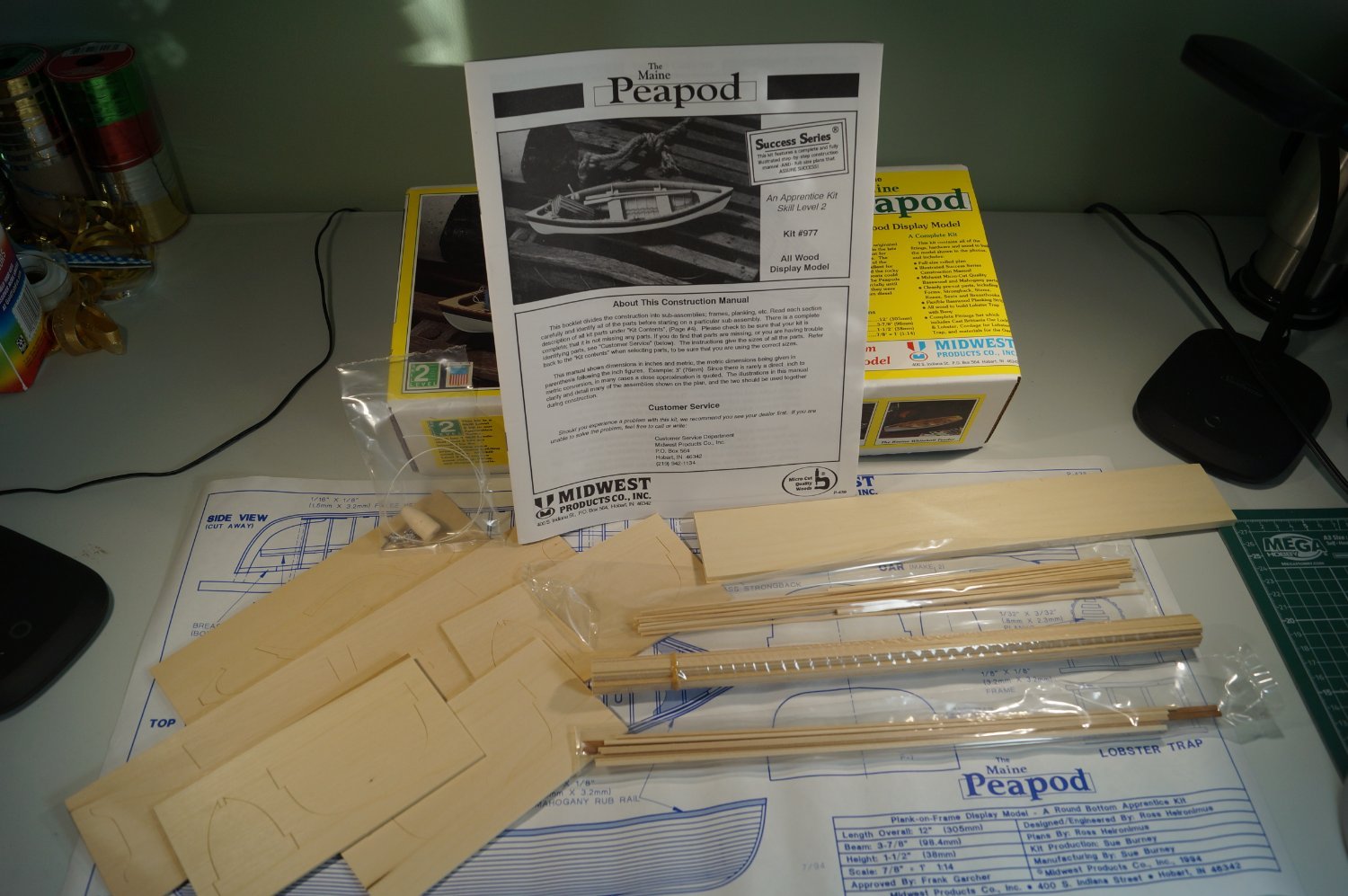
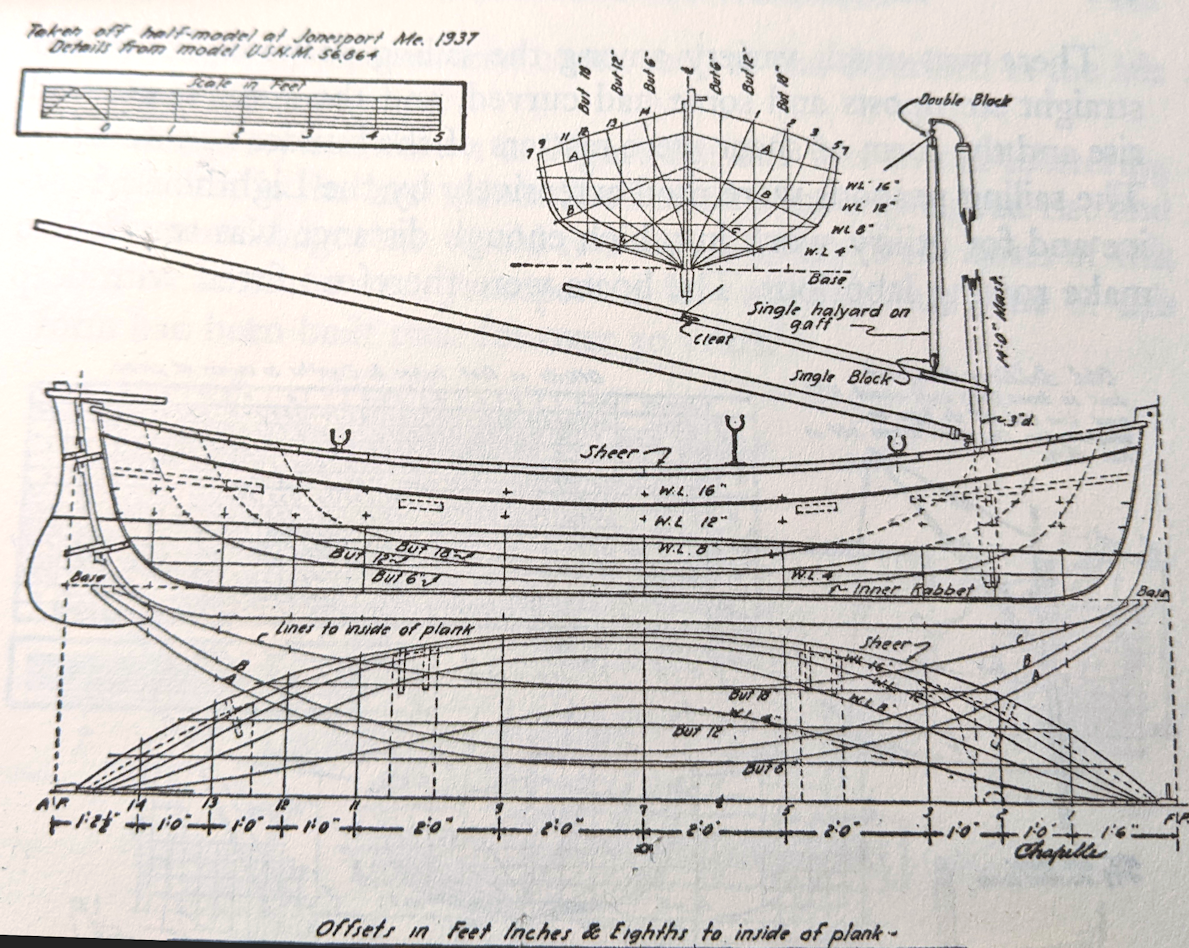
Preface I’m about ready to start my next build. Ready as in: it’s on the work bench, research done, and building process outlined, at least mentally. I got into the habit with in my previous build of, well, doing a build log. I think I have now established a discipline to continue that process. While this boat could correctly go into different launch dates, I chose this sub-forum since the version I am building has a 1937 date on the plans (see below). For this log, I want to post some information prior to starting the actual work on the model. As I pondered the build, I did what I think all modelers do at some level: research. The unusual aspect comes from the subject of a workboat which from my perusal of threads isn't a typical research subject. This research pointed a direction to take for the build. I started with the “Construction Manual” (instruction sheet) which, I think, is where most modelers begin when building a kit. Kit information Speaking of kit, here’s my thoughts on the kit itself. I’ve had this kit in my stash for years. I decided it was a good reentry into a wood model as I previously built a Midwest Model’s kit (The Dinghy). Additionally, I think I can do more than just “follow the instructions.” I wanted to look at upping my game by modifying this kit and build. If all goes per plan, I will have added some ‘scratch build’ skills to my toolbox. The kit is a Skill Level 2: intended for the person having “some prior experience building wooden boats.” I find that an interesting turn of phrase since in all likelihood most of us haven’t built a wooden boat. Boat models, yes. But not actual boats. (I know there are a few exceptions out there of people who have built a boat or two.) The kit has the necessary components to build a nice-looking model using basic skills of “cutting, fitting, and shaping wood.” As a side note, Midwest Models at some point in time quit producing these models. I am not sure when. Maybe someone can add a date to the thread. Recently, Model Expo reintroduced the kits from Midwest Models, including this kit. It appears that they kept the kit in its original form with die-cut pieces and strips for planking. While other kits for beginners and novices exist, this kit provides a good introduction to wooden boat/ship modeling. For those who choose to build this model, I hope this build log will prove useful. The kit has basswood die-cut pieces, strip wood for planking, and some mahogany pieces for the oarlocks and rub rail. It also includes material for oars, oarlocks, a lobster trap and buoy (more on these when I assemble those parts), and even a model of a lobster in cast metal. The instructions are clear enough to follow. I would suggest that some areas of the construction steps need a bit of research around beveling and bending wood. Nothing major, but if you haven’t done it before, look up some ‘how to’ information for techniques. The instructions include a couple of tidbits of data that got me to thinking about the build and raised questions about the boat. Like many modelers, I researched the boat. What I discovered pointed out ways I could modify the model for this build. Here’s what the instruction sheet (and box cover) has for background on peapods, particularly as related to lobster fishing. Being a double-ender (pointed at both ends), the workboat fits a unique set of requirements for those fishing for (well, trapping) lobsters. The boat can be easily rowed in either direction. This workboat design makes it suited for working around rocky shorelines. People rowed the boat while standing and added sails for getting to and from their traps and for use as lighthouse tenders. You find these in use around New England. They showed up in the late 1870s through the 1930s when diesel powered became the predominant lobster fishing boat. The concept of having sails and rowing while standing suggested some potential areas for modifying the kit. Beyond the instruction sheet history, background, and additional research In case there are some who don’t know the details of the boat, here’s some information you may find useful and gave me an insight into building this model. I found more than one type of ‘peapod’ during my digging around the Internet. This article shows detailed variations of lines for peapods and has some charts evaluating their performance, WoodenBoat link: Gallery of Peapod lines) I found the information interesting, particularly the range in sizes (13 to 16 feet) for the length of these boats. This 14-foot scaled model fits within that range. Like so many workboats, the exact origin cannot be specifically pointed out with 100% certainty. Several sources do point to North Haven Island, Maine, and Penobscot Bay as the birthplace. That is pertinent to this build since, by using the lines in the above ‘gallery’, I found this model fits the North Haven (Whitmore) lines. For a bit more details on peapod history, I suggest this link: North Haven Maine Historical Society: Peapod. I found a lot of differences in the various sources describing peapods. For example, the design likely started as lapstrake, or clinker built, with the planks overlapping. At some point, the construction changed or included carvel; planks butting against each other. The image below comes from a Wikipedia article about Clinker Boat Building . No other attribution noted. I think it does a good job showing the difference in the styles. This model uses carvel build. This drawing of the carvel does show the general need to bevel the planks for a boat. The amount of work depends, of course, on the actual lines of a ship or boat. Another area of difference exists around the sailing rigs. These boats were often used as lighthouse tenders. Howard Chapelle’s American Small Sailing Craft (Pg. 217-222) points out that peapods had a gaff mainsail or spritsail with a few having a jib tacked stem. A more contemporary set up includes a single lug sail or as a lug rigged cat yawl. If you want to take your model making to a new scale; say 1:1, you might want to visit Chesapeake Light Craft and their Lighthouse Tender Peapod. Building this full scale versions gives the experience of actually building a boat and not just a model. (Or you could say you built a 1:1 scale model?) They also include some details about peapods and their choice in sails for their boat kit. Some peapods were rowed (while standing) out to the lobster grounds and then sailed home at the end of the workday. It seems that these boats were not altered much for this dual duty. The sails were stored while working traps and stepped for the trip home. I did find a reference that an oar was used as a rudder which eliminates the need to manhandle the rudder. (About that standing up and rowing, you’ll have to wait until step 56 of the manual.) If one intends to use the boats mainly as tenders or supply boats, having a keel and rudder makes sense. These additions make a boat easier to maneuver with wind power. Again, I referred to Chapelle’s book for details. The plans there showed examples where the false keel is extended. The keel in this book ranges from 3” to 5”. (In Boat Modeling with Dynamite Payson, he shows a sailing keel of about 10 inches in the version he uses as a reference.) While adding a centerboard keel could be an option, from what I found in my research, that option apparently did not get used often, if ever. What this means for my build. I went over these details to give some insight on my thought processes and explain the changes I will make to this build. I plan on adding a sail rig. To do so I need to settle on a plan and determine how to add the keel, rudder, and rigging. Using Chapelle’s book (pg. 219 Fig 83), this 1937 version from Jonesport, ME will be my main guide. Using the kit’s drawing (blue lines) and adding the keel and rudder (red lines) I came up with this as my model’s plan. This keel works out to be 5 inches on the prototype which, I think, is a good compromise in the range of keels in the various sources. I will have to refine parts of the drawing when the time comes like the final shape of the rudder and tiller. However, I feel this will work well for my goals. I do have a general plan in mind for working all these changes into the model. I will cover those details at the appropriate points in the build. But as a preview, a couple of other changes requires modification to the (now bow) seat that will help support the mast along with a mast step. I haven’t looked at all the details for a boom, gaff, the ‘iron crane’ that sits on top of the mast, and the rigging. I do have a good idea on what these will look like. For the sail, my plan is to add a silk span sail. I intend to have the sail furled. (Hopefully that will hide any ‘newbie’ mistakes as I have never scratch made a sail nor worked with silk span.) I will be reviewing Tom Lauria’s video “Making sails for Ship Models from Silkspan” (Link to Part 3) for guidance. And somewhere in my notes is a link that indicates a method to cut the sail to make the task easier to model a furled sail. For this method you don't make the whole sail. A part of the sail in the aft lower corner is cut off to simplify the furl. Ready to start the physical work. I hope you learned something from my efforts so far. After all, a big part of the hobby and these websites comes from sharing information we discover as we progress. While it may not be 100% historically accurate, the model should be a good representation of a Maine Peapod rigged for sailing.

- 44 replies
-
- 6
-
-
- maine peapod
- peapod
- (and 4 more)
-
Thanks @allanyed. This looks a bit like a rabbet. Or am I over thinking this?
-
I am considering adding a keel and sailing rig to Midwest Models' Maine Peapod (kit). Peapods with sails were used as lighthouse tenders as well as for lobster fishing using sails to get to the ‘fishing spot.’ I thought a bit of modification of the kit would add a different dimension to this workboat. After reading appropriate chapters of Chapelle’s “American Small Sailing Craft…,” (and even Payson's "Boat Modeling") I found images where a keel was used with sails which, even with my limited knowledge of sailing, make sense. Here’s the reference I am using for the build from Chapelle’s book. (Note: I blame the perpendiculars' angle because I didn't shoot the picture perfectly level over the drawing.) Here’s my attempt to take the model’s assembly drawing and adding the keel (and rudder and mast). I trimmed a copy of the kit’s drawing and went old school drafting to add the additional components. The keel would be around 5 inches on the boat. Looking at other drawing examples I found keels ranging 3- to 7-inch. This example at ~5 inches and gaff rig in the book from a 1937 drawing seems a good middle ground. (I'll have some sail rig questions in the appropriate sub-forum a bit later. ) NOTE: The model is assembled on a strong back. So the main drawing (blue lines) is upside down. Doing so was much easier for me to visualize what I was doing (red lines) on my drawing board. I have a few questions and would appreciate some guidance and suggestions. Such will also serve as a 'sanity check' (which I usually fail anyway). 1. What might be some ways to keep the keel perpendicular to the hull bottom? (The boat has a rather flat bottom amidships and shapes more to a V towards the stems. It's a double-ender.) Does anyone have a suggestion for just gluing the keel in place at proper angle? I could use pins to hold the keel in place while the glue sets. Would that be a better approach? 2. I drew it as if replacing the false keel. Any thoughts on whether I would be better off installing the false keel per the instructions and then add the ‘new keel’ or replace the false keel? Considering the above question where I might ‘pin’ the new keel in place, putting pins into the false keel may be a better method to position the keel as the false keel (assuming I install it correctly) could guide installing the pins for the ‘new keel.’ Does this seem logical? 3. I would suspect it better to assemble the keel in pieces. The false keel is installed in two pieces. But I am considering three pieces cut to shape for my modification with a scarf joint or similar method to join them. Thoughts? Foreseeable problems? Concerns with wood grain and how to avoid problems? (The model is boxwood, so, I would likely use that same wood.) 4. I think so, but I want to ask: Does this seem a feasible approach? Or is there another concept/option to consider? 5. BTW, while proofreading this post, I found my note says add another breast hook to the (now) bow seat - that should be knee. That would add better support for the oversized seat, right?) For me (and my current skill set) I am entering unsailed waters. However, I think I can face the challenges. And this seems like a way to introduce some ‘scratch build’ aspects even if on a small way. Before I start the build, I want to at least feel like I thought through the process. Any input or suggestions will be appreciated.

-
@kevin - thanks for posting the 'Quick Find Indexes...'. That's a real gem!
-
QUICK-FIND INDEXES to BUILD LOGS FOR KITS
robert952 replied to Dan Vadas's topic in - Index of all kits by brand and subject
WOW! I just stumbled across this thread. I immediately put it in my favorites. Thanks for the work on keeping up with this project. -
Got my cuppa and getting up to date on this build.
- 38 replies
-
- 1
-
-
- Norwegian Sailing Pram
- Model Shipways
- (and 2 more)
-
Thanks for the comments. I am glad you found the log useful. I got to thinking about small pieces that were hard to get aligned like the ladders. A thought: Put a small piece in place (Ex. a ladder) bend one tab and align the piece (since there will likely be some motion of the piece. Put a dab of JB weld (which may hold better than PVA or CA). Let it set, then bend the second tab and 'weld' it in place. Not sure that will look good on things like guns which mount from back side and the tab is visible. That may help keep things in place better?
-
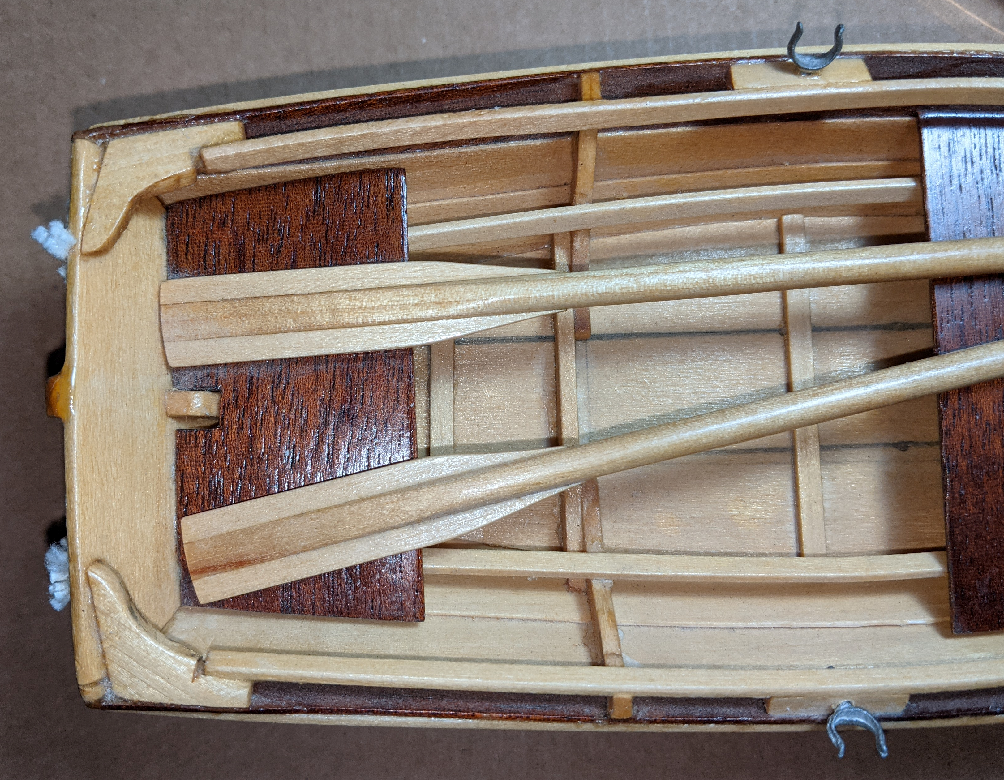
That's an interesting way to display the oars in position. Do you plan on having an elevated base like the you show with the brass piece? Will it have a crew?
-
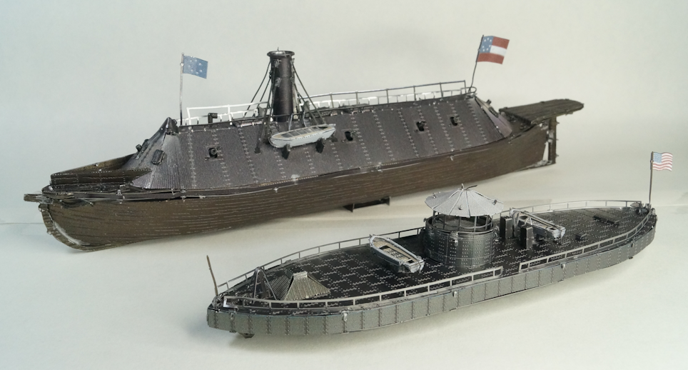
Closing thoughts on the completed project. I started the project back in October 2022. At that time my thoughts were to work with a very temporary work station of small end table as my downstairs was being renovated. Bending over the table to work on the model (CSS Virginia) proved to hard on my back. So I put the build on hold. I started back on the project at the end of January. I was able to work a bit more often and progressed on the assembly. But I did not work every day. I could work a few minutes here and there to add a couple of pieces. I didn't work every day on the models. I doubt I worked more than an hour on any one stretch. Which means that the total assembly time was likely in 25-30 hour area from start to finish. Working with metal definitely provides a unique experience. Those used to working with photoetched (PE) items can appreciate the differences of metal over other modeling media. Putting tab A into slot B seems simple enough. The tabs must be smaller than the slot to even work. But that little bit of space literally leaves 'wiggle room.' To get a tight bend on the small pieces proved to be difficult, at least for me. Bending a tab onto a flat surface could prove successful. Doing the same task on a curved surface creates loose pieces. Hence, despite the claim that no glue is needed, PVA (or similar) secures the pieces nicely. I would highly recommend using some form of adhesive to secure the pieces to anyone deciding to build this kit or likely other Metal Earth (ME) kits. The creep of tabs and slots accumulates which can make lining up subsequent sub assemblies a challenge as the build progress. However, overall, the end results are still good. The package shows a difficulty level of 8 on a scale of 10. The Virginia/Merrimac had more challenge but an 8 may be a bit high - maybe a 7. But that could be from the fact I have assembled a couple of other ME kits and new what I was getting into. The Monitor had smaller pieces to put onto the deck that proved to require a lighter touch when bending the pieces. But, I think that the Monitor was more on a high 5/low 6 level of difficulty. I enjoyed the kits. I would recommend the kit for a different type of experience. I would recommend doing a smaller kit to get a feel for how to work with ME kits. Be patient and make sure you look closely at the instructions. Clearly understand the required bends and their direction. Keep in mind that after 2-3 times bending a piece increases the chances a piece will break. Are the models historically accurate? Yes and no. The models show the concept and general configuration of the ships. If you look at decent source material such as drawings and paintings used in newspapers and books of the time, they match overall the shape and size of the ships. Even in these resources, there's a lot of variations in the looks of the ships. However, people with even a vague familiarity of the history behind these vessels will recognize them. As with a lot of models, the final results look nice and in this case a great conversation piece. My thanks to those followed the build and made comments. These were appreciated and provided information I can use in the future.
-
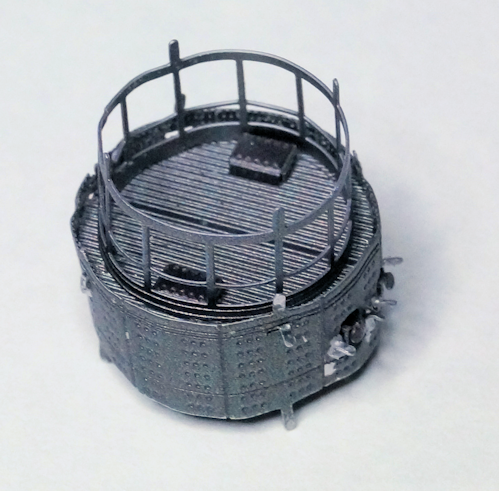
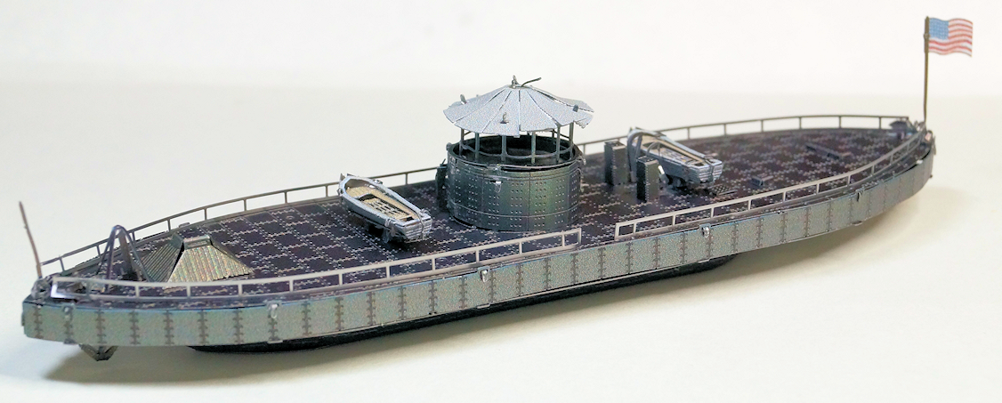
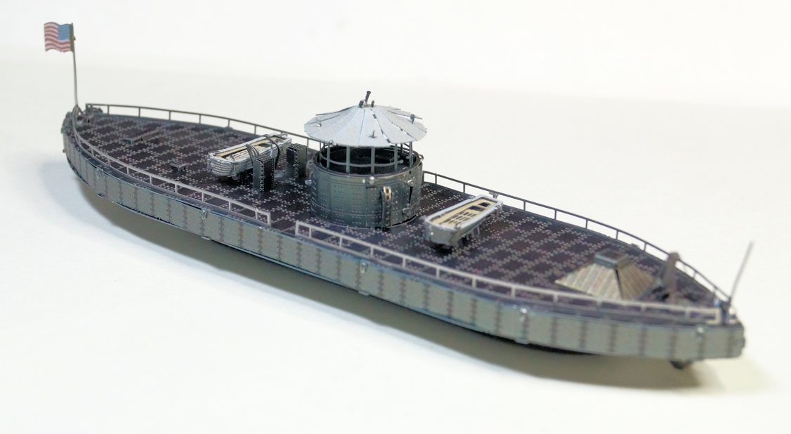
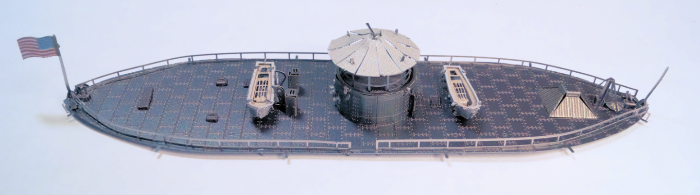
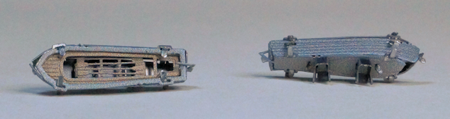
Step 29 (final step) putting hull and deck together Well, I must be living right. The side 'skirt' of the deck went on without a hitch. And the two pieces fit together very easily. Here's a couple shots of the finished USS Monitor. This completes the two models. I'll post some closing thoughts on the project.
-
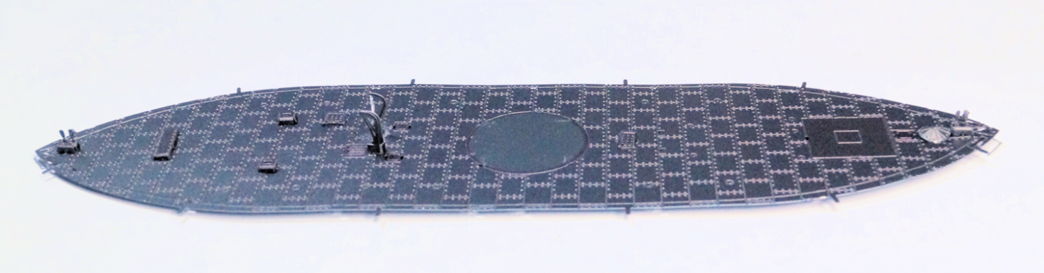
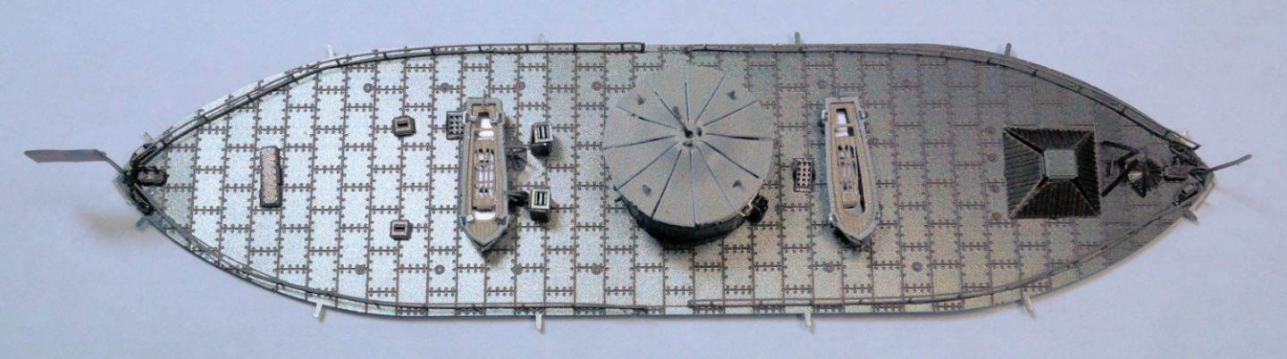
Step 28 Additional deck furnishings installed to deck This step consisted of around a dozen items assembled to the deck (not counting the previous assembled parts of boats, turret, etc.). Here's a couple shots of the completed step 28. A top down view And a bit more oblique view similar to previous step's images. Last step should be quick to do. It's adding the sides to the deck and then attaching the deck to the hull.
-
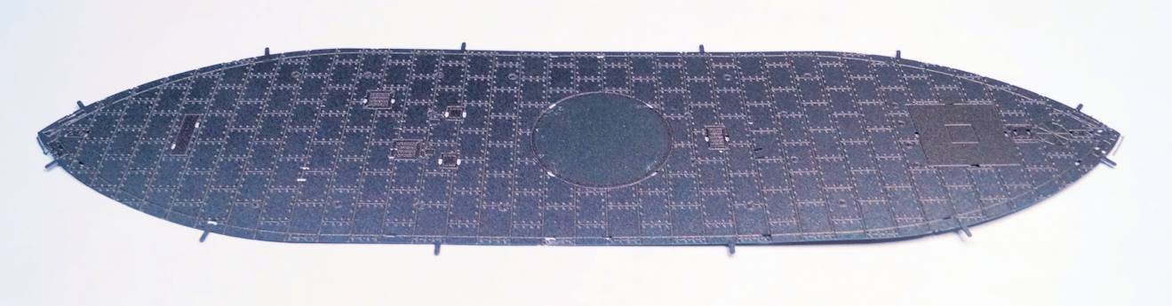
Step 27 Placing parts onto the deck Part 1 In this step I begin placing small pieces on the main deck of the Monitor. This covers davits, covers/hatches, and bitts mainly. I did have a problem with one of the davits. I was holding it in my pliers, looked away for an instant, and the part disappeared! Well, after an hour of carefully moving everything on the work surface and crawling around on the floor, I did not find it. Luckily, for some reason, there was an extra davit piece as used on the Merrimac. A minor modification and I have a passable replacement. (Don't look too closely. 🥴 Here's the deck without any of the greebles. And with the step 27 parts installed. Step 28 continues the process with installation of more small items (forward mast, flag, pilot house, railings, etc.) and the previously assembled turret and ship's boats. Then it's on to the final assembly.

-
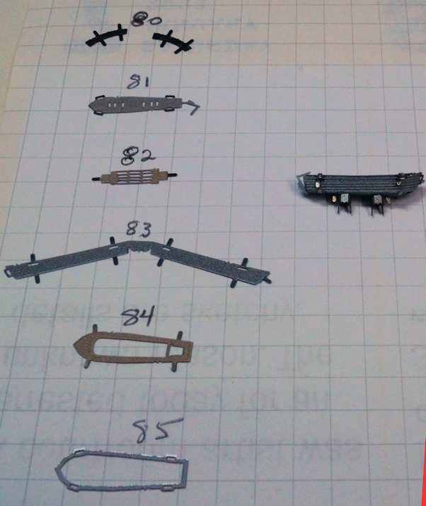
Step 26 Building the ship's boats This shot shows the pieces involved in building the boat and one boat assembled. For scale reference, the grid is 0.25 inch. A shot of both boats completed. The 'davits' are installed on the boat. They get added to the main deck in a couple more steps. The next step adds a few of the smaller (close to the deck) furnishings like bittes, boat cranes, etc.).
-
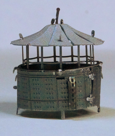
Step 25 Turret assembly. A bit of twisting (and I think stretching of the metal pieces 🤔) to get this together. This shot shows turret ready for the canopy top. And with the top installed.