
robert952
-
Posts
922 -
Joined
-
Last visited
Content Type
Profiles
Forums
Gallery
Events
Everything posted by robert952
-

It is a safe place to sell MODEL SHIPWAYS in Amazon
robert952 replied to Gus M's topic in Wood ship model kits
It's a 'buyer beware' world out there. I recall years ago on a user group where someone pointed out what was supposedly an out of production kit for a high price. One respondent made a comment that he found five copies of the kit at his local K-mart at a fraction of the cost. While it mighthave been an 'out of production' kit. it was still readily available. As pointed out, new folks to the hobby don't have a feel for what pricing should be and therefore a good deal. It's hard of us with a bit of knowledge to dig out such information, much less a person new to the hobby. -
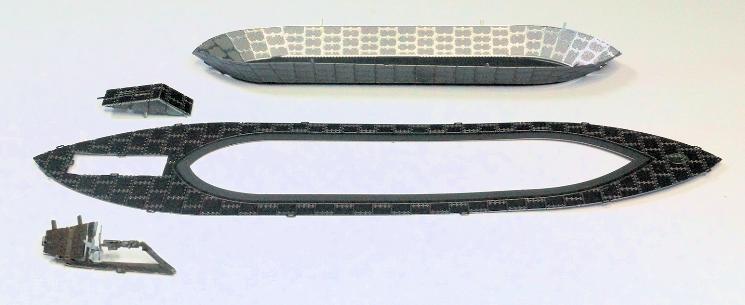
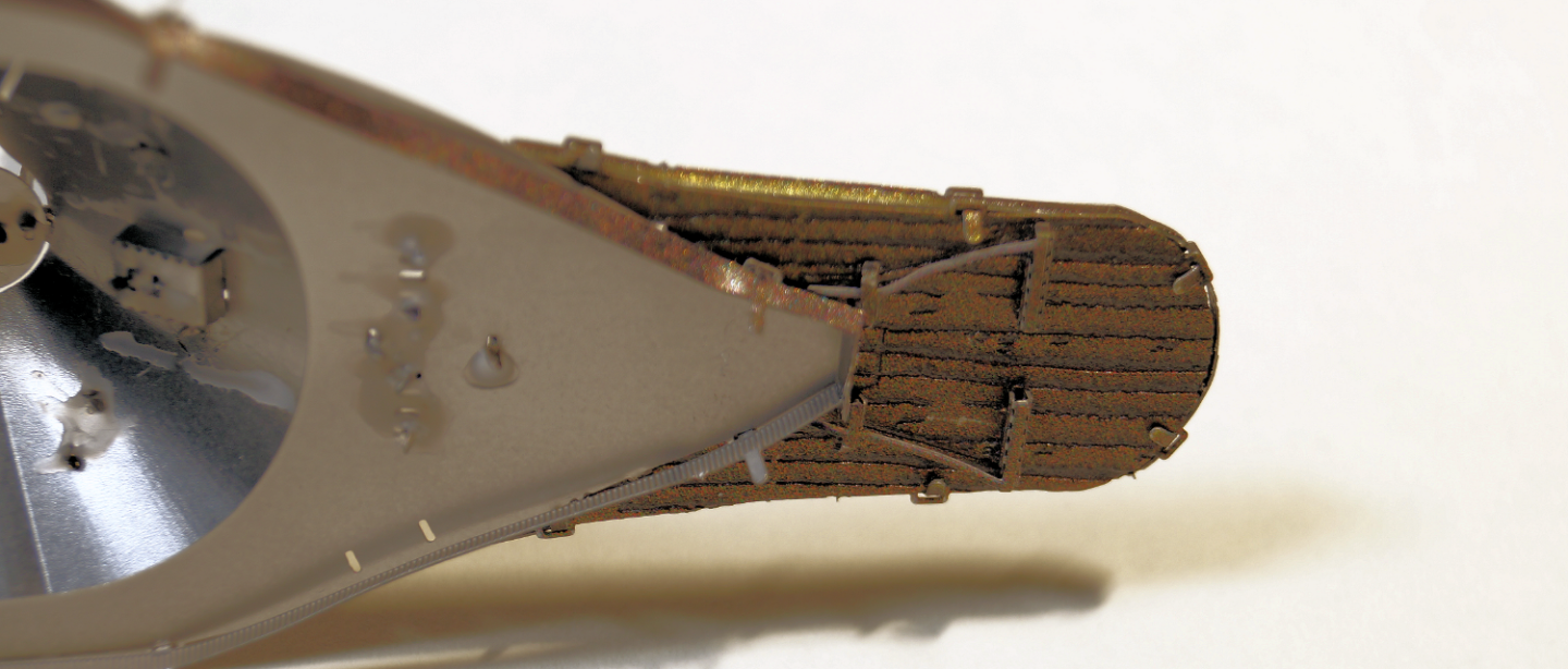
Step 24 lower hull, main deck, propeller/rudder with housing. I had no issues with these pieces being formed and fitting together. Here's the four pieces. The lower piece in the image is the propeller/rudder assembly from step 23. All are in their proper orientation and approximate location. Here's a couple of views of the finished assembly The turret, guns and awning get assembled in step 25.

-
Does is have any copyright date on the box or instructions? Maybe a very old (in modeling terms) model that had limited production. Per info at Model Expo - the company was founded in 1942. That's why I think it may be an older model.
-
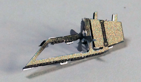
Step 23 Start of Monitor assembly - prop and rudder. By now I think most can appreciate the physical size of the components. So, I will just show the final form of the propeller and rudder assembly. The assembly is shown right side up. In step 24 this piece will be placed on the aft keel area of the hull. This model does the hull and deck assemblies first. Then upper deck housing the turret, railing, boat, etc. get assembled. As with the previous ship, the hull and upper deck get brought together in the final step. I hope what I learned building the Merrimac (Virginia) will allow a bit tighter assembly of the components for the Monitor.
-
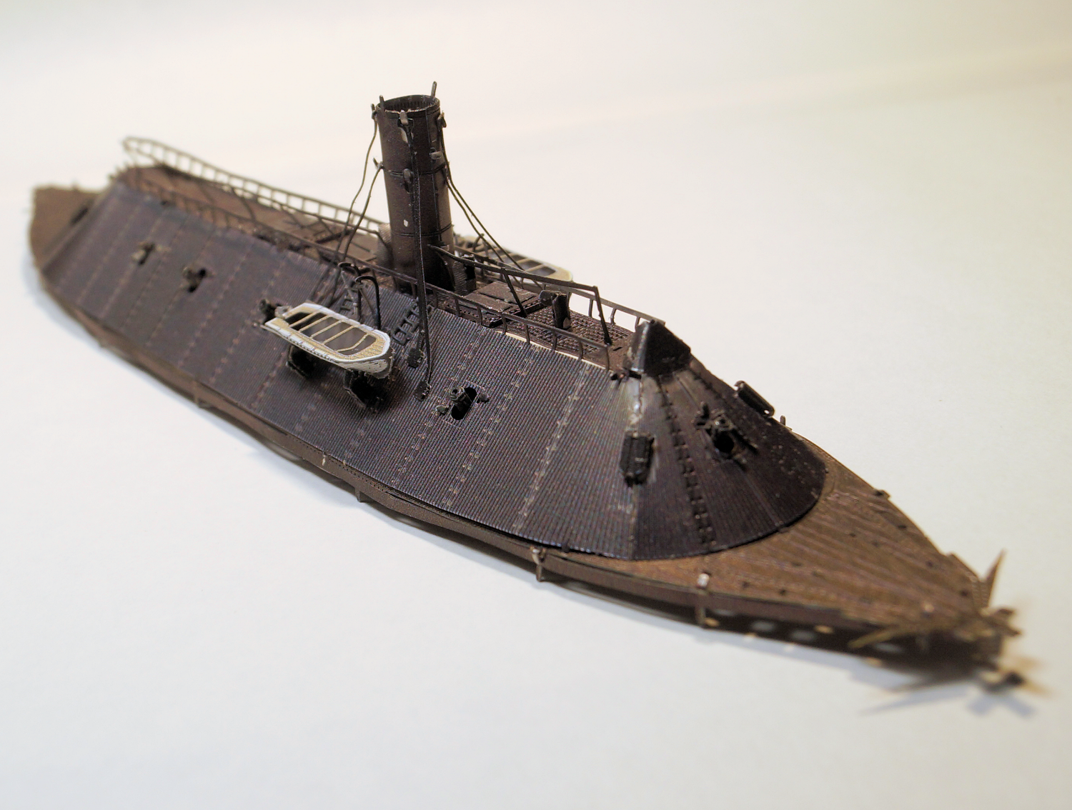
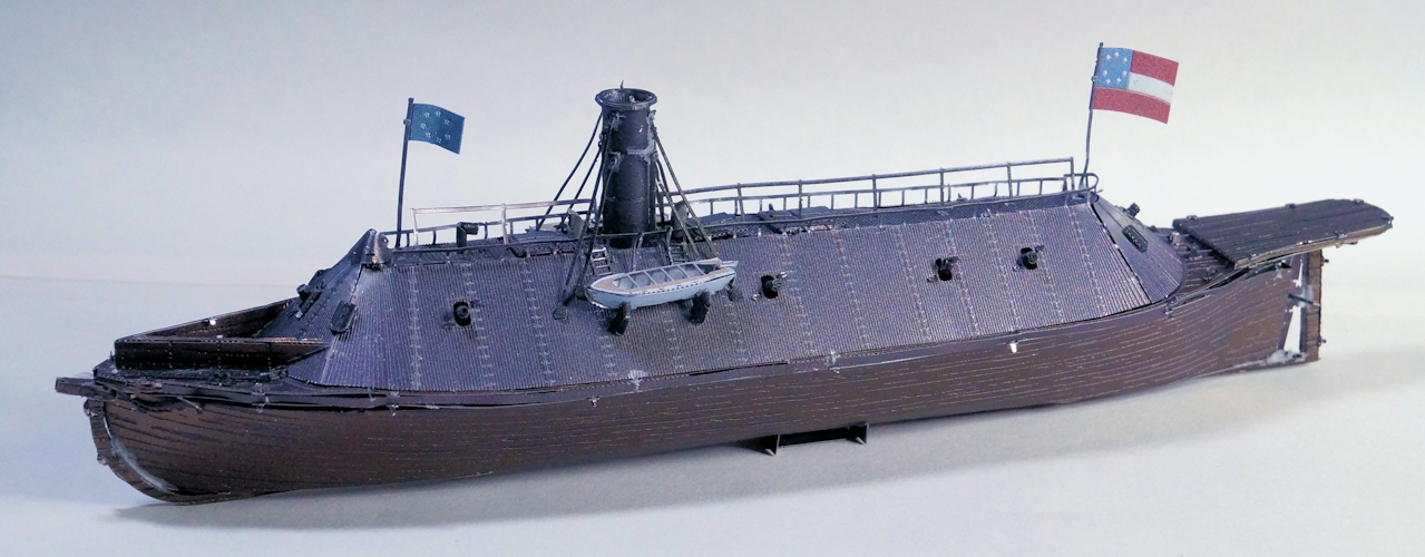
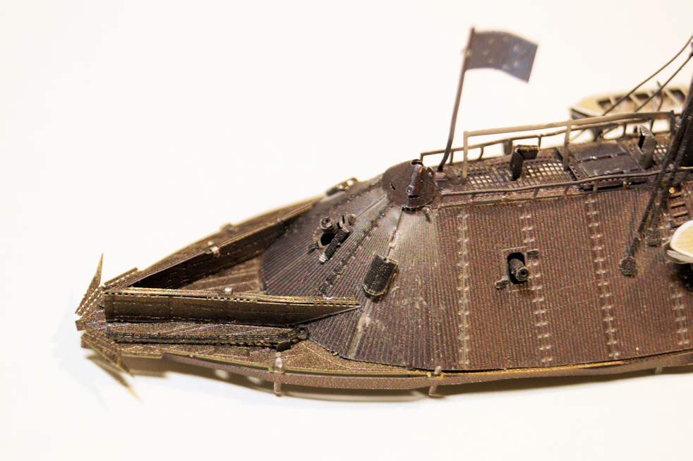
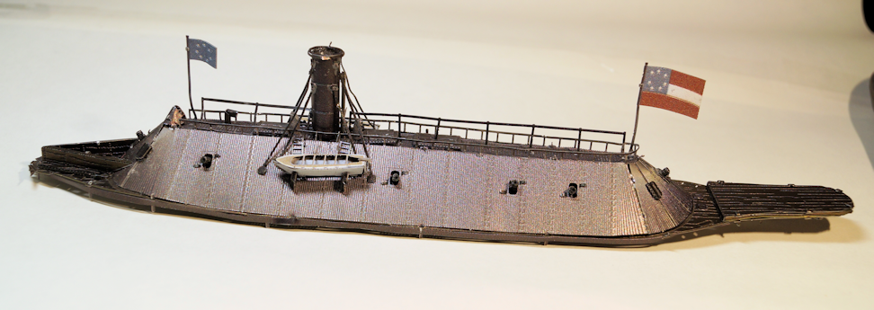
Step 22 Final assembly (Hull to upper deck) OK, as I predicted, there was a lot of twisting, bending, and forcing things to fit. The bottom band of flexed a lot. The top band of the hull twisted. Getting a good fit was (for me) impossible. But I managed to put it together. One the 'good side,' I went out to the Metal Earth site to see if there were some secret hints or such. They have 360 degree views of the model with zoom. While their model is far superior to mine in fit. I see that the assembly has some gaps and bends. I also not that the bends of the tabs are not as flat as I would expect. (In my opinion, my folds and bends on the ship's boats is a bit better than their version.) I will try to find a way to bend and twist some more and glue the assembly into a tighter fit. Not so sure I can do that though as there's no convenient way to 'clamp' the assemblyl. Here's the CSS Virginia (what ME calls the Merrimac) completed at step 22.
-
Looking good. I am enjoying following all the builds of this model on MSW. I should have a good idea how to approach my build of this model in my stash.
- 28 replies
-
- 2
-

-
- Lowell Grand Banks Dory
- Model Shipways
- (and 1 more)
-
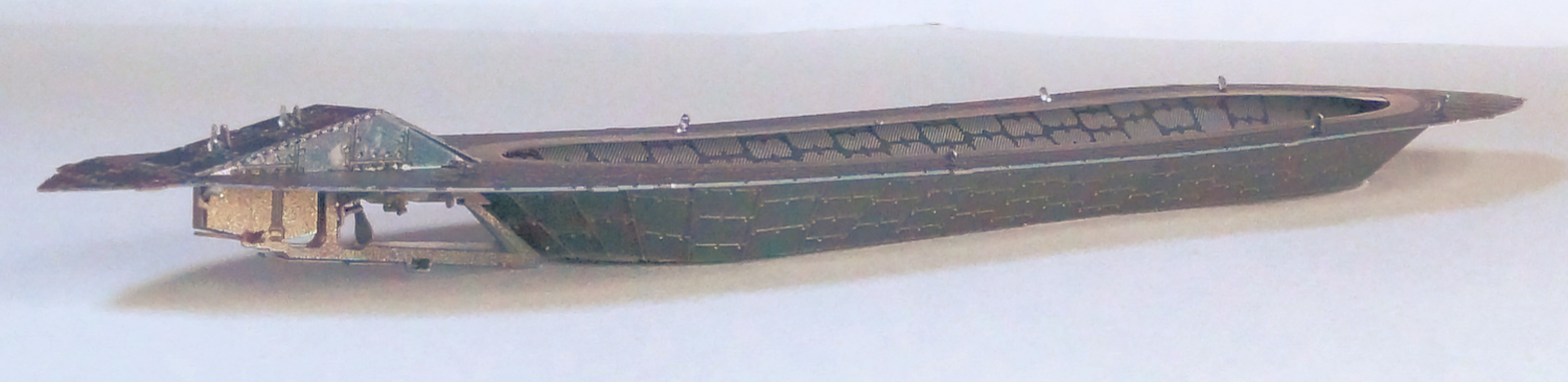
Steps 20_21 Adding sub-assemblies to hull Step 20 Attach propeller (Step 17) to aft keel (Step 19) Last post I made a comment about no rudder on this model. I understand why. That portion of the stern which holds the propeller is probably the weakest part of the model. I had a devil of a time even getting it close to position and secured. The prop blades ended up very loose. The stern post wanted to twist when bending the propeller into position. A lot of PVA ended up as the only solution that worked. (I considered epoxy, but the tight quarters, that would have been messier.) Step 21 Attach keep pieces, anchors and band (Step 16) The keep pieces fit easily enough with little effort or tweaking. The step shows installing a bow piece to the forward band. A part of Step 21 installs the anchors. These two pieces interfered a lot with the forward part of the band to the hull. I did what I could but the fit is less than ideal. I will likely end up figuring a way to glue it into position. The rest of the band fit ok with minor bending and twisting of the bow to get the shapes to match. I considered using PVA to secure the band to the top of the hull. However, after doing some test fitting of the deck to hull I see there will be a lot of finagling, bending, twisting (and probably the used of a couple of dirty words.) I will have to see how that goes. Then I will apply glue to hold things in place. Meantime, here's an image of what the piece looks like at this stage. (I 'jumped ahead' and bent the mount so that the hull sits upright for the photo. As preview, Step 22 is the last step for the Merrimac (their name, we all know it's actually the CSS Virginia).
-
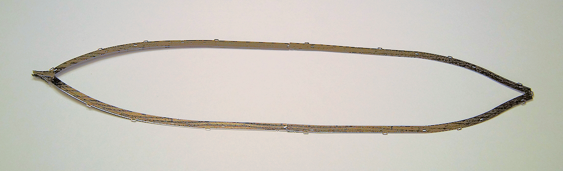
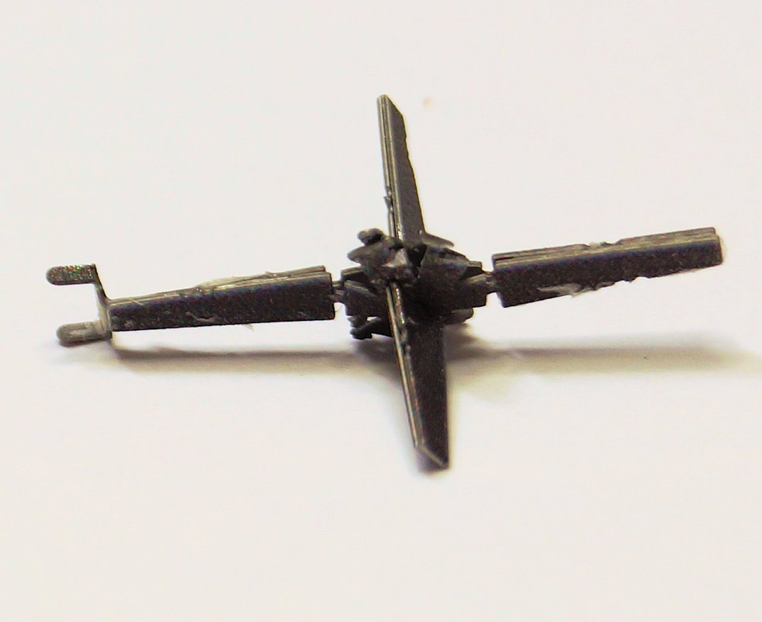
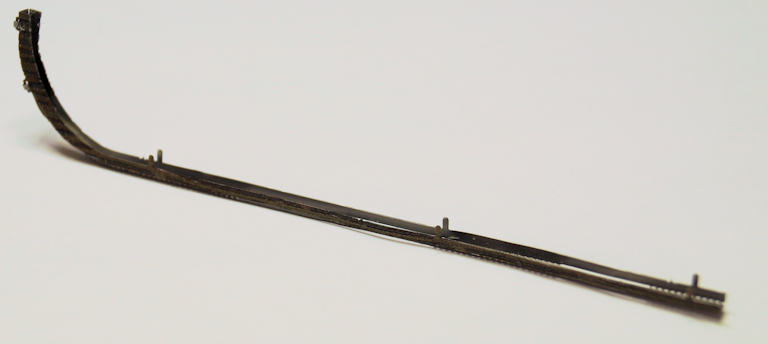
Steps 16 through 19 Various sub-assemblies for the hull. These steps were pretty quick to do. Each assembly will likely require some tweaking as I put these sub-assemblies onto the hull. Step 16 Frame for upper hull. Two pieces meeting in the middle. This will allow putting the two halves together (hull and upper deck) in latter steps. Step 17 Propeller The assembly for the propeller was quite tricky to put the two halves together. Step 18 Forward keel Pretty straight forward. The tabs will fit into the bottom of the hull and mate with the aft keel Step 19 Aft Keel The interesting discovery here is that the model does not have any specific pieces for the rudder which would connect off of the stern post. The underside of the aft deck shows detail for the mechanics of the rudder. From a few images I found, the rudder does extend to the end of the upper deck. Upcoming Step 20 shows the propeller mounted in place and a flat piece to cover the stem. It is good I looked ahead as the propeller gets placed into the keel and then bent into position. (I was ready to bend the section up against the sternpost when I asked myself - are you sure this get's bent now?)
-
Looks good. Getting my cuppa and a comfortable seat. Looking forward to the build. The pizza cutter is an interesting concept.
- 31 replies
-
- 1
-
-
- Grand Banks Dory
- Bluejacket Shipcrafters
- (and 1 more)
-
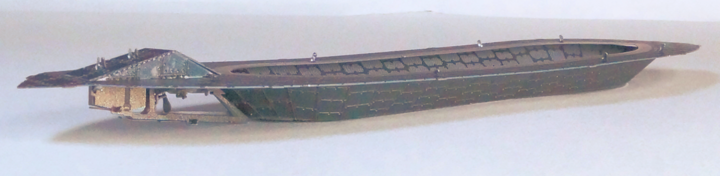
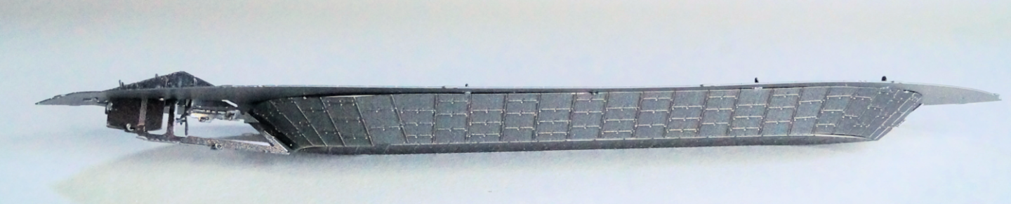
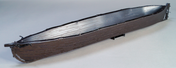
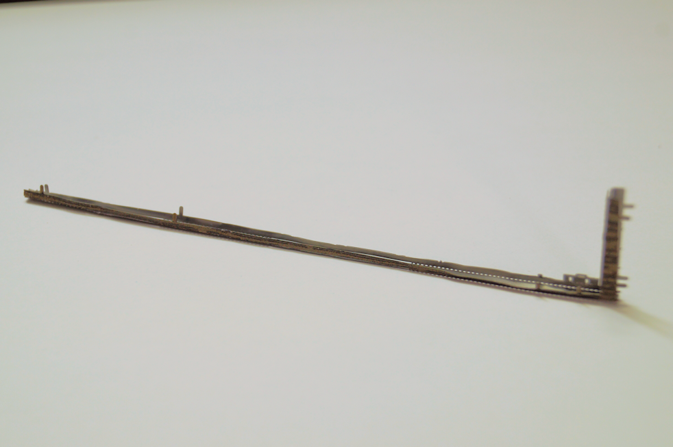
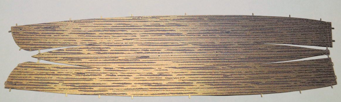
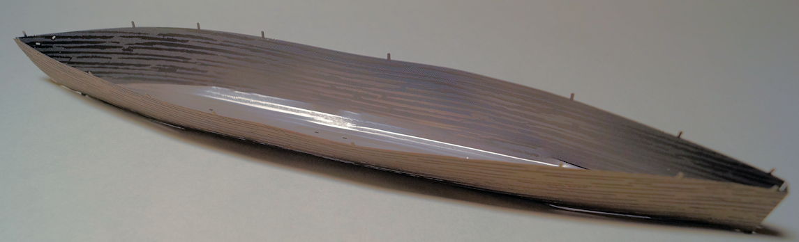
Step 15 basic bending of the hull I did the basic bend and folding of the hull. I did not do much to finalize the shape. The next steps assemble a frame work that allows mating the hull and upper decks together. I imagine there will be some twisting and finagling to get them together. Here is the hull just off the sprue And (surprise) generally bent in the proper shape. As I said I suspect some bending and twisting as the two main parts get joined. Before that happens there's some steps bending the aforementioned frame along with the keel and the propeller and it's supporting frame.
-
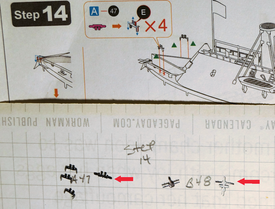
Step 14 installing bittes (mooring posts) Here's the small pieces (on a quarter-inch grid). The arrows point to the pieces as cut from the sprue. My big mistake here was folding on in the wrong direction, so it will be shiny and not etched. (Too delicate to risk unbending and rebending.) And hard to see but here they are installed.
-
Nice work. Look like the making of a side gig. I assume that's an air line of some kind on the side.
-
Welcome aboard. Looking forward to seeing some of your work.
-
Thanks @Mjohn I am glad to share the experience. It's a good way to show the details of the model and point out the process. While not a typical medium (metal), I hope it provides information of some use to people.
-
Your wooden kit progression - go big, or keep learning/practicing?
robert952 replied to Esap's topic in Wood ship model kits
I don't have a lot to add to what others have said. Start small and have an attitude towards learning. I made the noob error of starting out on a big project and got overwhelmed. But I did not get discouraged. I realized I had a lot to learn. Then I started reading build logs and other threads, magazine, books and attending workshops. (I have what I think is a pretty decent reference library, too.) One piece of advise: don't be overcritical of your own work. My family looks at my models and think them very nicely done. But they have even less experience and exposure to the hobby than I have. However, I can look at an older build. At the time I finished the model, I was pleased with the effort. Today, several years later, I am still pleased with what I accomplished. (It was the Dinghy by Midwest Models.) However, I am also proud that I can look at the model and see areas that "aren't quite right" and things "I can do better next time." I use a critical eye without being overcritical. I think that shows the gain in knowledge over the years. I just have to practice and improve the skills. One other piece of advise: while moving to bigger and more complex models is an admirable goal, don't overlook the potential of other small projects. Bigger may not always be better. I have seen those I consider super model builders do some great things with smaller projects by using advanced techniques. You don't need to scratch build a complete model. You can learn and explore some of those aspects of advanced model making by 'kit bashing.' Improve on the components in the kit to make it more historically accurate or change the aesthetics. Explore 'third party' add-ons and material. Some examples I have seen are use of different rigging blocks, applying a different approach to making sails, and making components closer to proper scale. They also provide a reasonably priced way to learn over buying a 'the great big boat' model. (I'd have to see if I could find it again. But I was fascinated over the approach a modeler took building a detailed lobster pot. Even something like that teaches new ways to approach a model and provide learning opportunities.) It all goes back to the idea several expressed here that we have to be willing to learn as we evolve. Just keep in mind... you should enjoy the journey. -
Nice finished build. Very well done. I look forward to Part 2 of the series (The Sailing Pram). I got these three as Christmas present. I find the various build logs very helpful to give me a preview of the processes involved.
- 6 replies
-
- 2
-
-
- Grand Banks Dory
- Model Shipways
- (and 1 more)
-
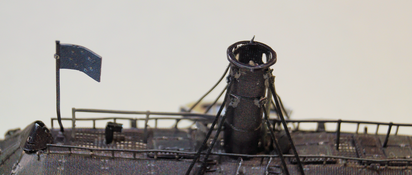
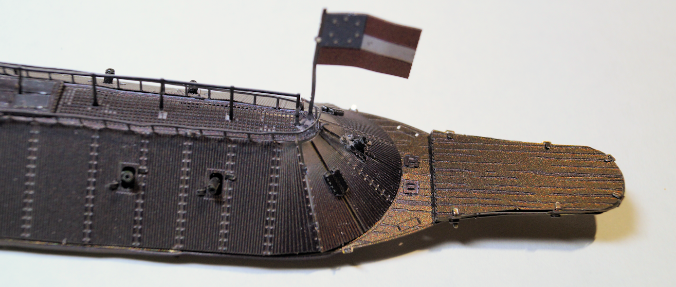
Step 13 covering installation of sub-assemblies from Step 10,11 and 12: smokestack cap, flags, and a couple of other details. Again going in the sequence shown on the assembly manual, a few pieces get installed to begin this step. The list starts with a ring cap on the smokestack followed by the flags. I am finding it nearly impossible to handle the model without bending the flag staffs. On the good side, looking ahead, the upper part gets completed in step 14 The next part of the process was what will (I believe) be the base for a couple of bittes on the stern between the bulkhead and deck extension. After installing the aft flag, the rail is wrapped (or in my case warped) around. That piece has taken a beating. The aft deck from previous assembling process goes on next. Took a bit of finesse to get them in place. Here's a look at the underside of the aft deck assemblies. The bow ram assembly was next. Surprisingly, I must have gotten lucky with the V-bend of those pieces. They neatly dropped into place. The lats pieces were the anchor chains. That action finishes the procedure in Step 13. And here is what the vessel looks like at the end of Step 13. Step 14 adds the aforementioned bittes (6 of them). And Step 15 begins the hull assembly process. (I bet you've never seen a ship built from the top down.) 🤔 I'll likely put those two steps together in the next post.
-
I have a room I haven't vacuumed for 2 years because I know there's some small parts hidden in shag. An unusual model. Looking good!
- 68 replies
-
- 5
-

-
- Morel
- Master Korabel
- (and 1 more)
-
Thanks. I am just getting over a head cold and cough. A coughing fit doesn't help either.
-
Jumping on board to watch this build. Looking good. I enjoy and learn from how people solve the challenges they come across.
- 48 replies
-
- 2
-
-
- Bowdoin
- BlueJacket Shipcrafters
- (and 1 more)
-
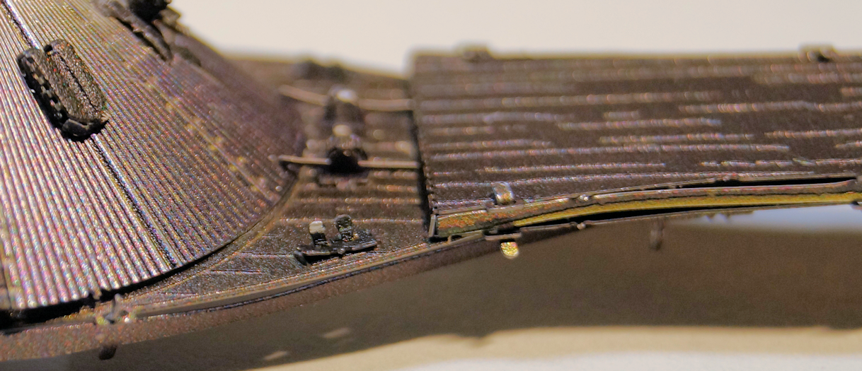
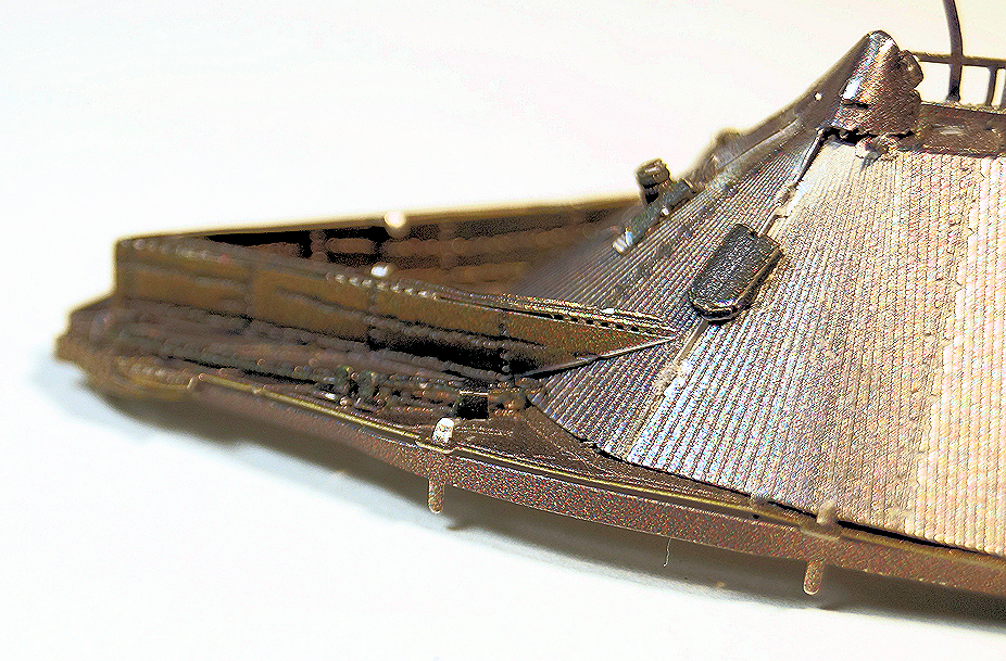
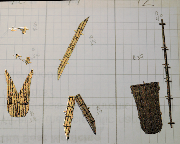
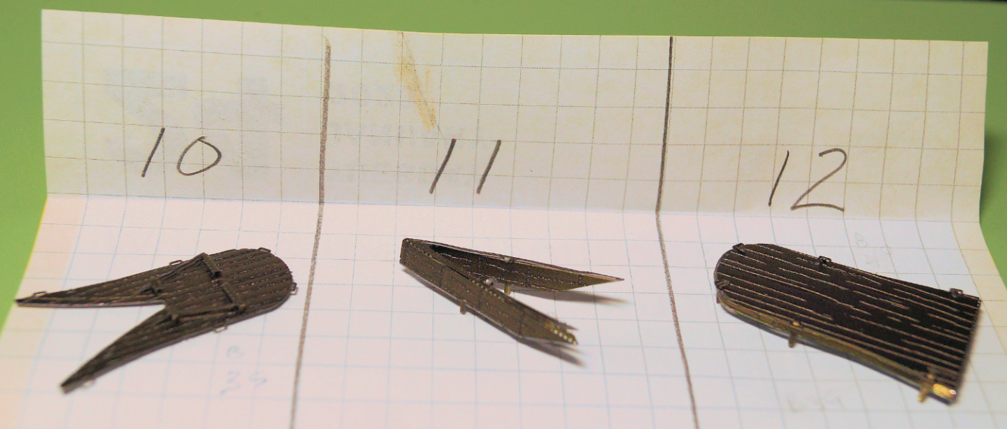
Steps 10 (aft deck lower piece); Step 11 (bow ram); Step 12 (aft deck upper piece) Overall, the steps do not take an inordinate amount of time. But, it's a hobby. What else do I have planned? The assembly of these three sub-assemblies took a bit over an hour. The time consuming part is taking care not to over-bend the pieces and yet bend them enough to "put Tab A into Slot B." Here's the pieces involved for these three steps. (left to right). They have been cut from the sprue. The grid is 1/4 inch to help with the sense of the size of the pieces. Interestingly, they show the assembly of done upside down. It's more of "however, I could hold it and get the tiny pieces to fit into the deck slots." In Step13, assembly 10 is installed with the etched side down. Step 12 piece will be installed etch side up over Step 10 assembly. Spoiler alert: These pieces will extend over the propeller assembly later on. The finished pieces look like this. Step 10 is shown etched side up to show the detail that will nearly be hidden in the next step. Ready for Step 13...stay tuned.
-
No problems, Bob. It's all just part of the conversation. Glad you pointed this thread to Glenn. The more the merrier. Thanks for stopping by and for your comments, Glen. For what you get, the Metal Earth models are reasonably priced (IMO). I have a few others from ME in my stash. No ships (at least I don't think so) though I did do their Golden Hinde a while back.
-
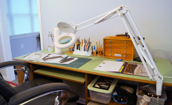
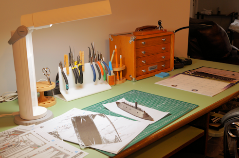
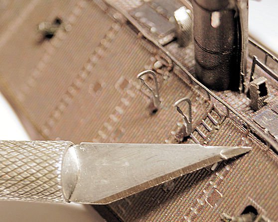
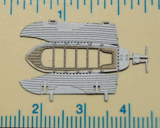
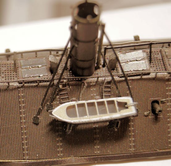
Step 08 and Step 09 mounting the ship's boats and smoke stack support/braces. Real life, as usual, has a way of interrupting a build. In this case, I found it too hard to bend over the low table I had been using as a temporary solution. So, I stopped work on the model. There were also a couple of 'road trips' to visit parents and brother. Then after renovations work was done, we had to put final touches on living area (rugs, blinds, unpacked kitchen ware, etc.). That took longer than I thought it would. We are still looking for some items we know we packed back in September, 2022. My favorite tea mug among them. Also, I reworked an older computer desk to make a workbench to assemble models. I had to promise the Admiral I'd keep it neat since it sits just off the living room. So, far so good. (I even bought some odorless thinner for later work.) It's not an official part of the build. However, I am pleased with my efforts on the workbench. So, here's a couple of pics of my finished workspace. I put VYCO (vinyl material used on drafting tables) on the top, and had to repair one end of the desk that had holes I drilled for computer cables. The keyboard tray makes a great lower work area and photography stage. The pull out printer tray is a convenient storage area using boxes to organize stuff. Picking up at Step 08, this step assembles the ship's boats and supports for the stacks on the port side. The davit pieces attached to the ship. The "Exacto" knife gives a sense of scale for these pieces. The boats are folded and the support pieces mounted to the boats. Again, at this scale, objects and assemblies are quite small. Here's the boat as cut from the sprue. After mounting the boats, support pieces for the smoke stack are installed. This completes the port side portion of the assembly steps. Since this photo was taken I tightened the bend on the bow of the boat. Step 09 repeats the process for the starboard side. As before, I used some PCV to secure the parts in place on the underside. Also, as I was handling the model, the support pieces got bent. Once I am finished handling the model, I will see what I can to to straighten and flatten them. Here's a shot with both boats and all stack supports in place. For the next part of the build log, I'll put Steps 10, 11 and 12 together as they are small sub-assemblies for the fore and aft decks. I should be able to do those in next day or two.

-
Nice looking stem post. The challenge of solving problems like these make for great learning experiences. I like how you used rubber bands. I'll be challenged to keep the pressure equal when I get around to building this. The big advantage at this site are the builds. Sometimes you have to dig around to find specific models. Sometimes you can find a similar problem on a different build, though that takes a bit of digging.
- 40 replies
-
- 1
-
-
- Lowell Grand Banks Dory
- Model Shipways
- (and 1 more)
-
@Roger Pellett @Bob Cleek @DaveBaxt Thanks for the replies. I appreciate the input. As I implied, I thought I read it somewhere. I have two or three sources to go back through in my library to see if I can find this info. For some reason it seemed in the context of lighthouse tenders and fishing boats that operated close to rocky shores. But, memory fails me on the details. I looked in the area I had been perusing in Chappelle's American Small Sailing Craft. No joy there. I'll probably come across it when I reread some other article or thread. Thanks again for the input.