
robert952
-
Posts
922 -
Joined
-
Last visited
Content Type
Profiles
Forums
Gallery
Events
Everything posted by robert952
-

Planking Book?
robert952 replied to BWDChris's topic in Building, Framing, Planking and plating a ships hull and deck
@RossR I had forgotten about the NRG Half Hull. Thanks for the reminder. It's now on sale at the NRG store, too. -
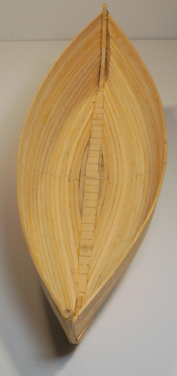
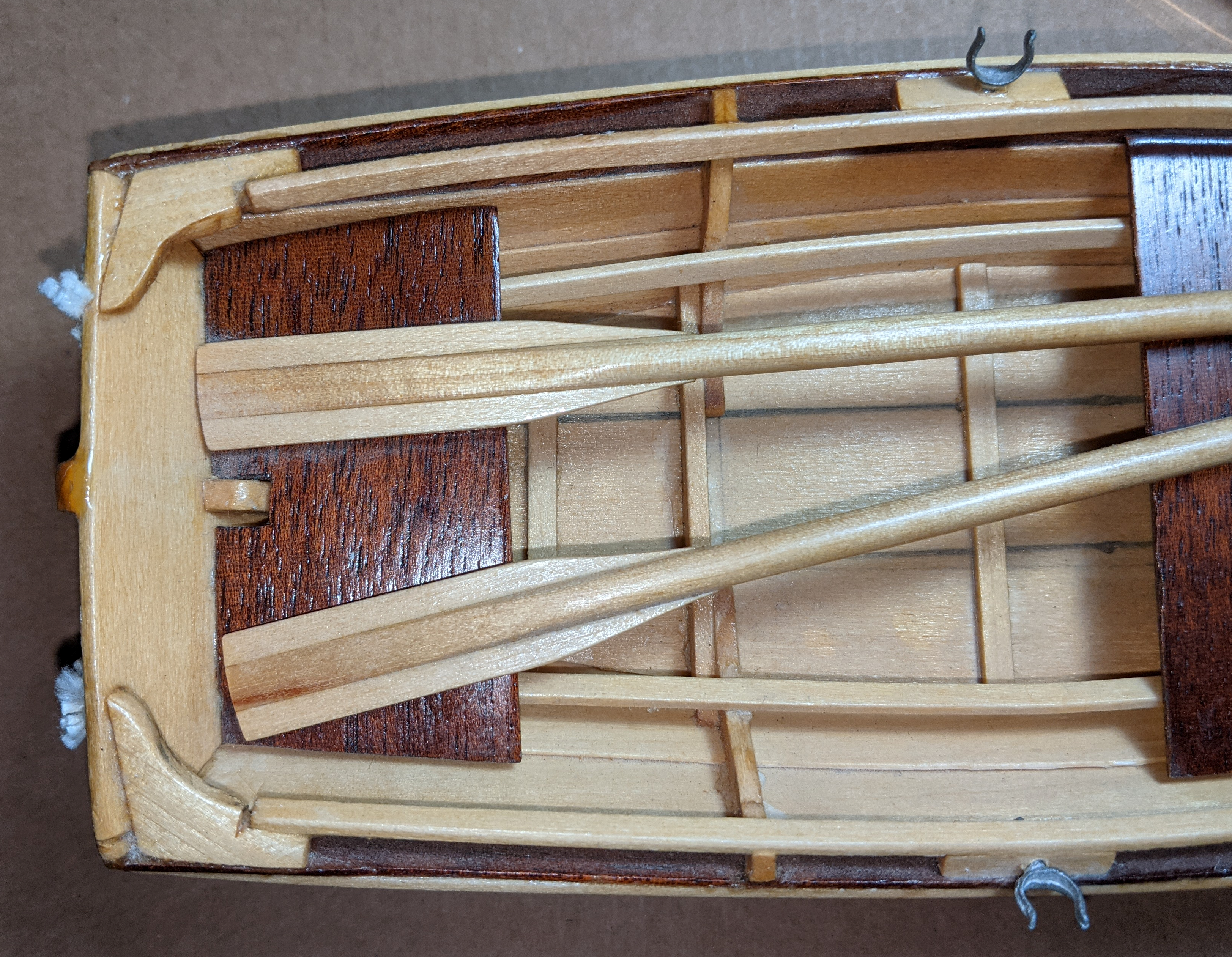
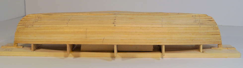
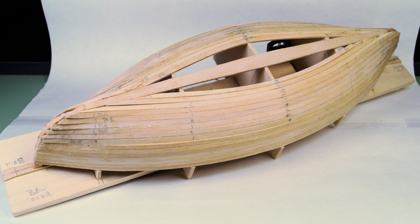
Removed boat from the form. Since I had success with loosening the planks with white vinegar, I figured that would be the same solution for this phase. A bit of vinegar on a cotton swab at the two stem joints. Let it soak a couple of minutes. Then gently pried the stem from the base board. Only a bit of force needed to break the hull loose. The instructions indicate the hull might pull in on the sides. They suggest using the midship bulkhead as a brace. I saw that same suggestion made in a couple of build logs for this kit. However, I did not have that issue. I measured the beam on the form before I removed the hull. I measured the beam again off the form. Exactly the same measurements, no pulling in. However, I will remove the center bulkhead from the base board and have it ready just in case. The lines on the keel board are guide for the ribs (solid lines) and floor boards (dashed lines). Once the ribs are in place, the form will hold its dimensions. When I am ready for installing ribs and floor boards I will plan for (and likely install) the mast step. On the 15' prototype, that point is 2-1/2 ' in from the bow stem. For this 14' version, the dimension probably will be close to that. If I calculate properly it should be 2' 4" from the bow. In reality, it's likely not to matter too much at this scale. However, it gives me a target location. Here's a another views. For now, it's time to do some sanding and filling and more sanding.
- 44 replies
-
- 3
-

-
- maine peapod
- peapod
- (and 4 more)
-
Planking Book?
robert952 replied to BWDChris's topic in Building, Framing, Planking and plating a ships hull and deck
Adding my welcome aboard. Here's my typical long winded answer/suggestion. I was thinking along the same lines of @SkiBee . What are you wanting to build? You say you are new to model ships. You may want to review this thread which offers a lot of general advice for those new to this hobby: A Cautionary Tale. I would suggest you consider starting with plank on bulkhead type over a plank on frame. I haven't tackled a POF and it may be awhile. But that's me. Proceed at your own pace. Your results may vary. If you haven't got a model in your stash and just now considering a kit, I'd suggest getting your feet wet with a simple model that has only a few 'planks'. Model Expo carries Model Shipways line that has some kits designed for the beginner (Grand Banks Dory and Sailing Pram). They also carry Midwest models (Dinghy or Flattie) which have a few boards. The models are aimed at the beginner that can start you on a path to learning about planking. If you have some experience with model building or a related hobby you may feel confident enough to build a more advanced model. (Shop around for what your budget can handle.) As to your specific question about books: @prutser suggestion is a good source. I haven't read @Paul Le Wol suggestion but I'm sure it has information you will find useful. (Thanks for the recommendation, Paul. I'll run out there and download it myself.) Many books on ship modeling have chapters on planking. Examples The Ship Model Builders Assistant by Charles Davis and Ship Model Building by Gene Johnson. I have these two in my in my library. These also cover other aspects of model ship building. There's a lot of other models and books out there. Find your comfort level when determining what to build. As @Knocklouder says, you are in a great source of info here at MSW. Use the search box to find build logs on the boats I mentioned. Ask specific questions. You will likely get several answers and suggestions. Read through build logs to see how different people plank their models. Also, you get a preview of models out there you might want to consider. There's several on the Dory and Pram that have been built or in the process of being built. (If you want to see my example of planking, I just finished planking Midwest Model's Maine Peapod. Link to my build log is in my signature below. Maybe not the best example, but I am pleased with how it looks.) -
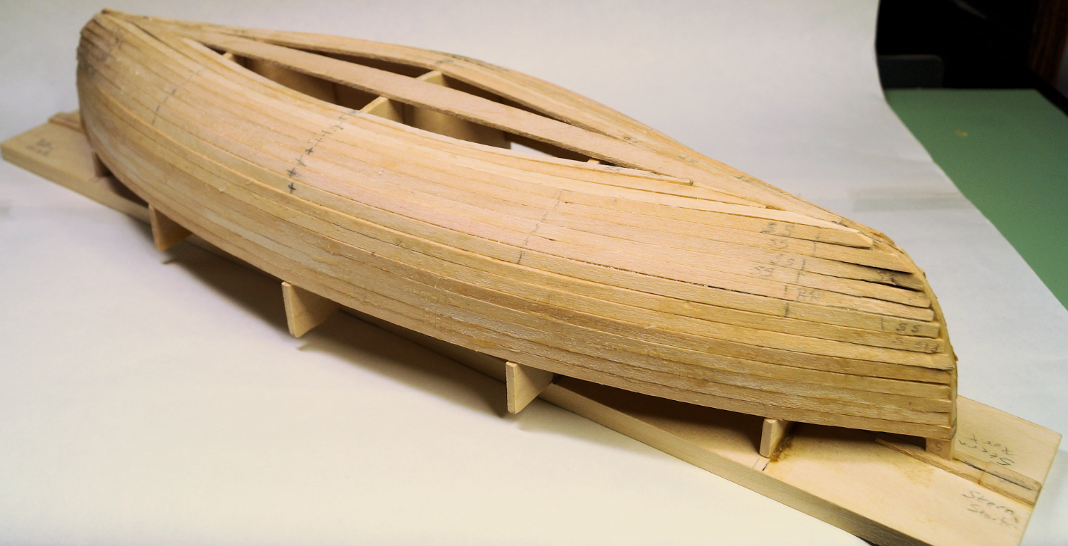
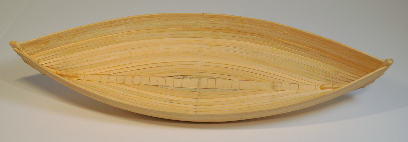
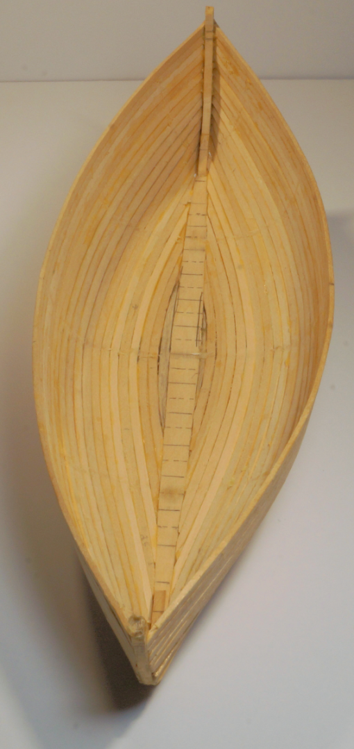
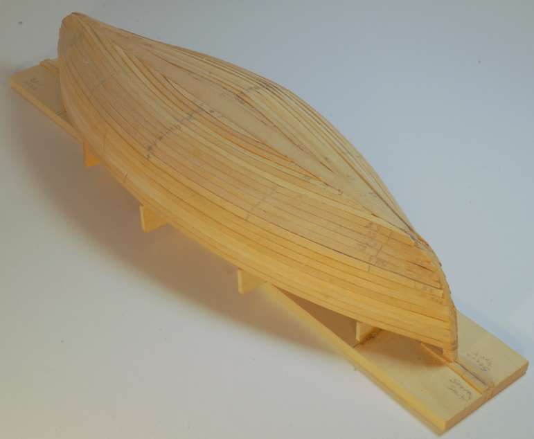
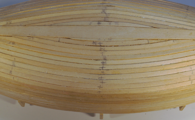
Planking done. Finally! In this image the lines you see near the sheer (bottom on the image) are random pencil marks - not cuts or gaps. They just suddenly appeared and I see no reason why I would have put them on the hull. (Is there such a think as work bench poltergeist?) The little 'center marks' and short lines follow (more or less) the bulkheads were my guides to make sure I placed the board in the same position while I bent and glued the planks. . Another angle. I have a bit of work with sanding and filling (and sanding some more) as you can see by these images. If anyone sees an area I need to be concerned with, let me know please. The last few planks on the keel proved a challenge to me. (Again, pencil marks are not cuts or gaps on the one plank off of the keel plane. I found it interesting that the small bend/radius was harder to do than the longer curved pieces. It was difficult to hold the boards in place as they dried since there's no room for clamps or clips. I ended up with a lot of painter's tape. Here the gaps will need filling more so than other areas of the hull. Next steps: Remove the hull from the strong back. That should go ok with little or no problems. I think I did a decent job by using bees wax and breaking errant glued joints as I went. I will know in next day or two. (I have a new PC game to play with and will likely spend some time there.) I have done a little preliminary sanding on some of the planks to fair the keel lines a bit. I plan on taking my time on the fairing. I checked my sandpaper supply. It was in disarray and required a bit of reorganizing. Now all the grits are sorted. So, I won't have trouble finding what I need. After that I will create the keel (as previewed above) and assemble that to the hull. Then I will decide whether to paint the hull immediately after installing the keel or wait until I get the ribs and floor boards installed. (Any insight will be welcomed.)
- 44 replies
-
- 5
-
-
- maine peapod
- peapod
- (and 4 more)
-
My other Hobby by Javlin - Tabletop/Nightstand - 1/1
robert952 replied to Javlin's topic in Non-ship/categorised builds
It's a nice looking stand regardless of the woes you had. Good Job in my book. -
My other Hobby by Javlin - Tabletop/Nightstand - 1/1
robert952 replied to Javlin's topic in Non-ship/categorised builds
Following this build log. Looks good so far. -
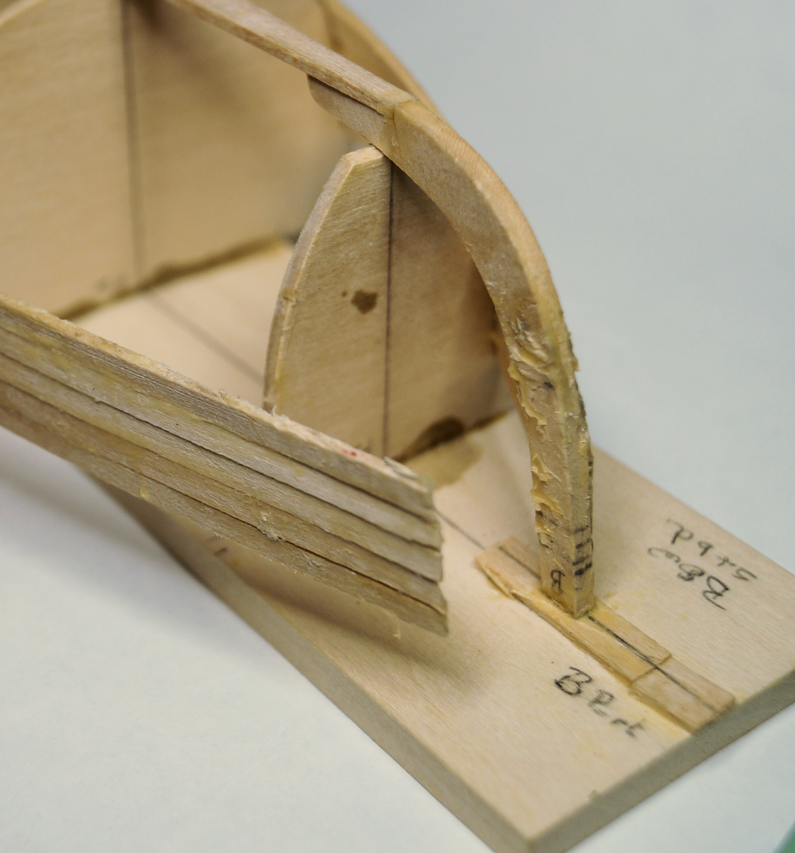
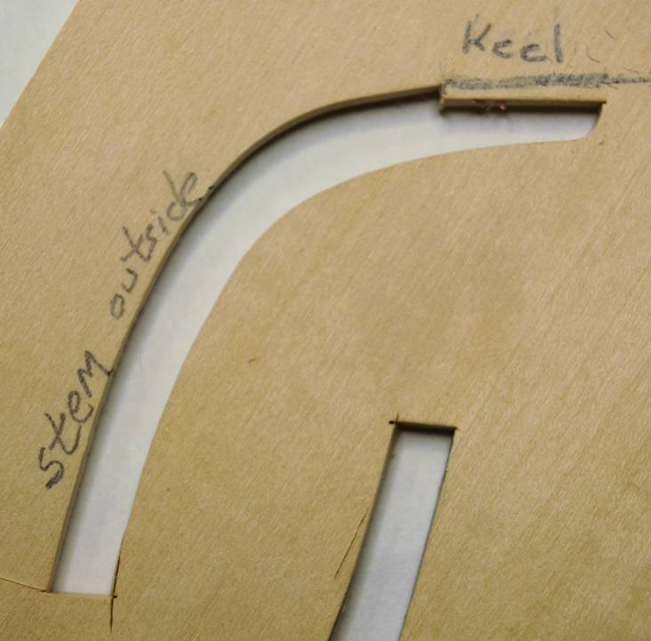
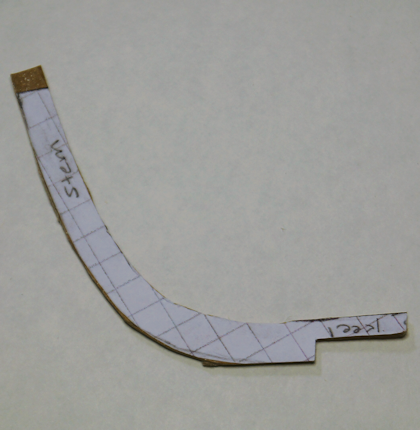
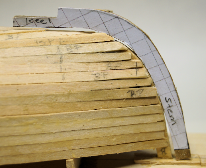
Preview of revised keel. Per the instructions, after faring the hull a false keel is added: two 1/8" pieces attach to each stem and meet in the middle of the boat. While that may be a several days away, it's never to late to think about this step. As I said, I want to model this after a drawing in Chapelle's book referenced at the start of this build log. Per that drawing, the keel extends from the bottom of the hull for 4-3/4". The top of the stems taper to 3-1/4". I will use these dimensions, though I may forgo the taper as then I can use a constant measure for the stems. To create a pattern, I used the original die cut sheet that held the stems. The outside measure of that stem will be the inside measure of my keel. I then cut a cardboard pattern as a practice test piece so that I can check the fit. Then a quick check to see how close the fit is at this point. Not a bad fit considering the boat is on the form. Once I fair the hull, I will repeat the process adjusting as needed for a good fit. The rest of the keel sits on the flat bottom. A scarf joint (as you see on the pattern) will be the method to assemble the keel to the hull. I will make all three pieces for the hull and make sure they fit well. I will use a similar approach to make the rudder for the boat.
- 44 replies
-
- 4
-
-
- maine peapod
- peapod
- (and 4 more)
-
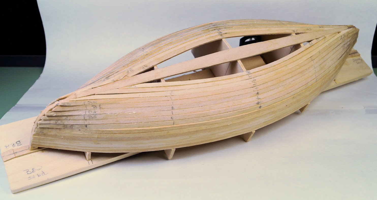
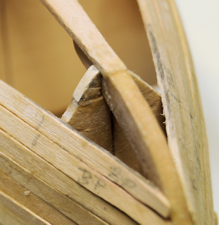
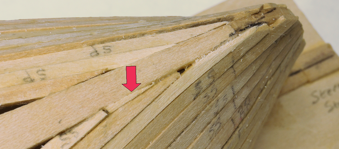
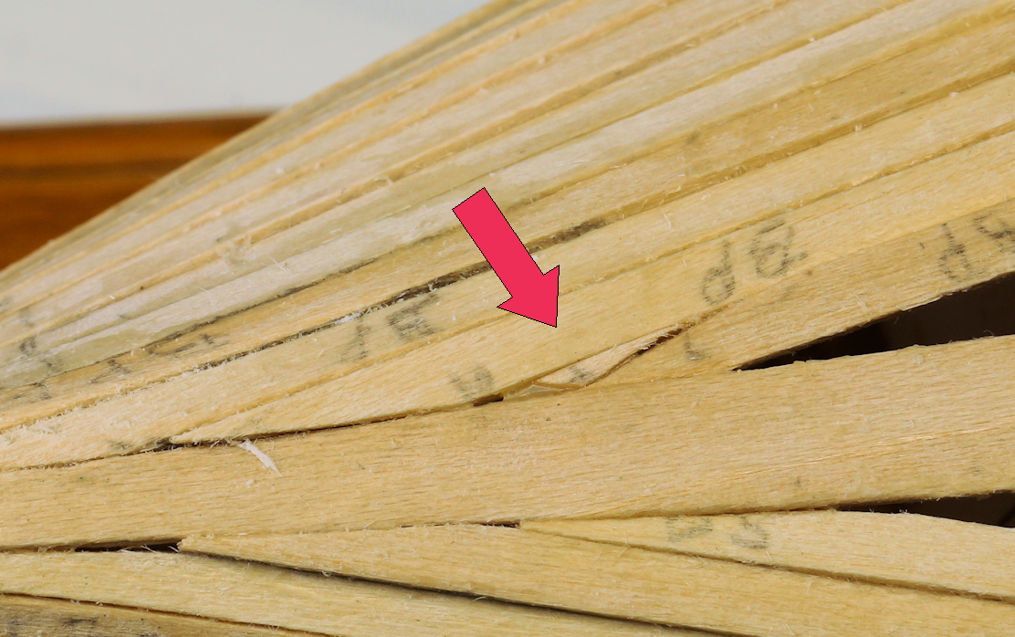
Bulkhead repairs; update on plank progress. While waiting on the glue to set on my latest work, I got the camera out and took some photos. I figure this is a good time to update my build log. Bulkhead repairs. As a follow up to the previous post, here's the results of my repair on the bulk heads. They did the job (as you will see shortly) of supporting the next couple of planks during the assembly process. On the 'bad news, good news' I managed to break off one of the tips. However, since it was a clean break and the piece did not get lost on the workbench (or sucked up by the vacuum, I was able to just glue it back in place. Update of planking progress I have made progress. I estimate two+ a sliver planks on the (arbitrary) port side and three plus a sliver on the starboard side. That may give a sense of scale for these images. For me, planking takes patience and practice. As I have progressed on this hull, I think in some areas I have improved my process and skill. But I suspect even at the best of times, I will (and do) make a mistake. However, I get some satisfaction from successfully repairing or correcting my slip up. The latest example is seen below. Near each of the arrows on the images below you will see the planks were sanded too much or cut too short. My over enthusiasm in sanding left a couple of holes. While both of these might have been fixed later with the inevitable wood filler that I still need to use, the filler has something to adhere to and not be a messy plug. I fixed these with some of the small end pieces I have from the planks I sanded very carefully to fit those tiny pieces into the holes. Some fillers to make a better fit. The last plank on each side will like end up as a very small filler between the plank and the keel board. This model did not use a rabbet for the planks. I should be able to finish putting those in sometime next week...at least that's my plan. Then I remove the hull from the bulkheads and start fairing the hulls by sanding, then filling the gaps, follow by more sanding. Hopefully, I won't have too many repetitions of those steps.

- 44 replies
-
- 3
-
-
- maine peapod
- peapod
- (and 4 more)
-
Airbrush Paint
robert952 replied to CLovehitch's topic in Painting, finishing and weathering products and techniques
@Bob Cleek Thanks for posting your detailed response. At the risk of hijacking this thread but an apropos continuation here's a couple of questions. I have a model in process and I am pondering on I will paint it. I dug out my old air brush so I can practice with it. And I have seen more and more articles covering the use of oil-based artist's colors. The arguments seem very valid. So, I may give them a try. I plan to seal the model before painting and wonder how oil based paints work with sealed wood? Do you use another coating of some kind over the sealant before spraying oil based colors? One thing I will add to the discussion, be sure to practice using the airbrush with your 'brew.' A minor shift in the "brew" can make a big difference on the finished project. (My experience comes from long ago when I was doing photo retouching and graphic art type stuff.) -
Scale converter for Android (iOS maybe?)
robert952 replied to robert952's topic in Modeling tools and Workshop Equipment
Absolutely. @mtaylor. I have looked at and used plenty of on-line tools. (And I have used the spreadsheets available.) However, there is something to be said about having these new-fangled devices and seeing what's available for use with out any connection to internet. This is completely stand alone app. I see I forgot to mention the price: Free.- 2 replies
-
- 5
-
-
- scale convesion
- scale
- (and 3 more)
-
I found this handy easy to use scale converter at the Google Play store. I don't know if there is an iPhone version. (Maybe somebody can check and post response here.) It's called Scale Converter, by Scalar Pint. No popups, no ads. Simple tool. Very user friendly to convert between modeling scales and measurement units. Below is a screen shot of the app on my Android based phone. Drop down menus will allow selection of scales (1:1 through 1:20000) and length measurement (inch, mm, mile, km, etc.). No 'custom scale' available. However, the list is pretty extensive. The terms are typical inches, feet, mile, mm, meter, etc.) Type in measurement on either line to convert a length measurement. Example above: 1:1 measure of 4.75 inches converts to 0.339 inches at 1/14 scale. If you need to change measurements "on the fly", just click on the appropriate drop down to change. For example, in image below, I just clicked on mm in the drop down to get the 8.618 measurement. The icons at the bottom of the screen: double arrows - scale conversion; colon- scale calculator (input two length measurements); percent mark - percent calculator (input two ratios to get percentage factor between the scales); and decimal to fraction conversion (only works with yards, feet, and inches since metric is, well, metric). Again, input data on either line and conversion works. (If you need just a metric converter, use scale converter, put both scales at 1:1 and change length measurement term to metric on one and imperial on the other. Also, enter numbers on one line (either one) and your conversion gets reflected in other line. Hope you find this 'review' useful. Again, if someone can look to see if an iOS version exists and let us know here, I'd appreciate it.


- 2 replies
-
- 2
-
-
- scale convesion
- scale
- (and 3 more)
-
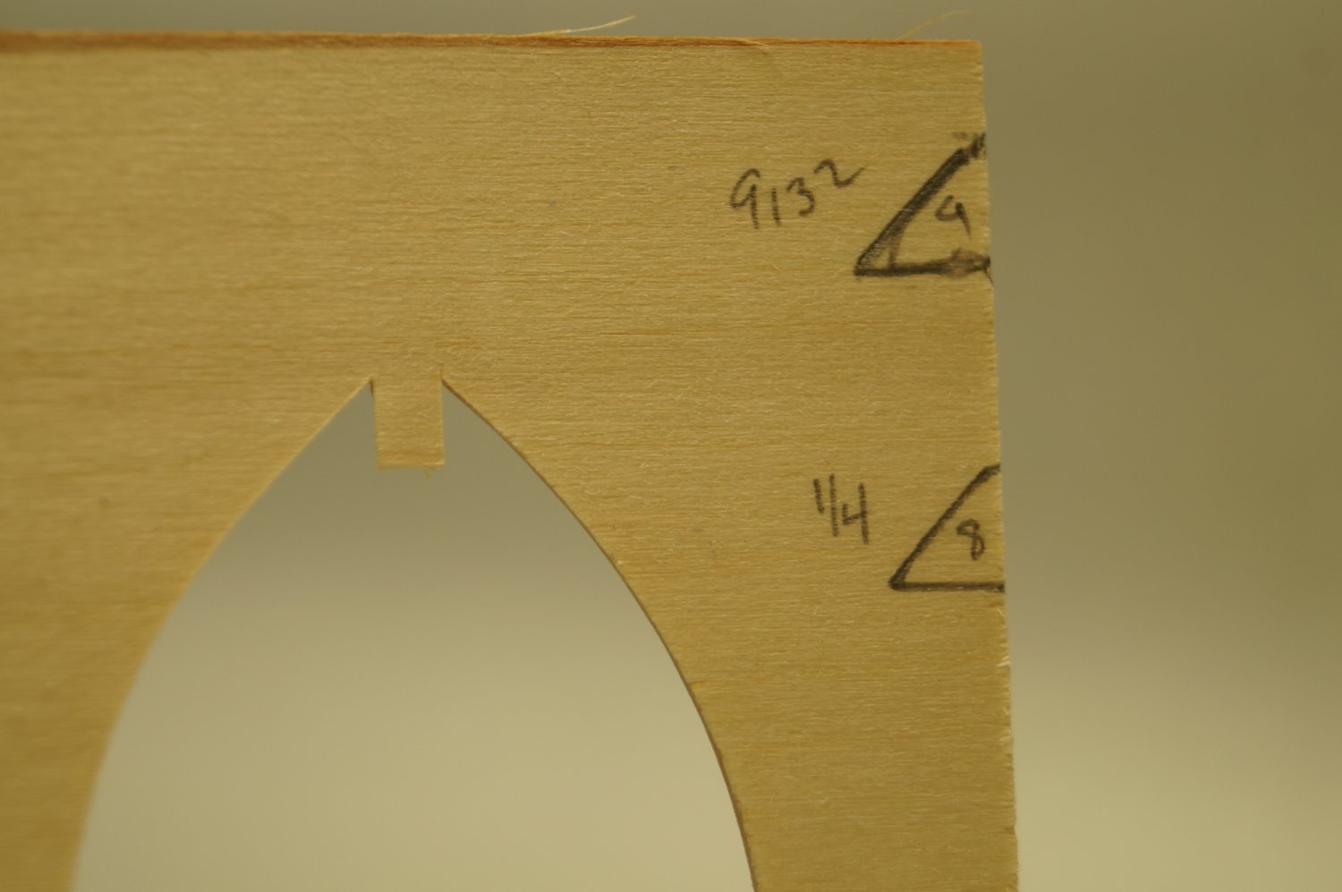
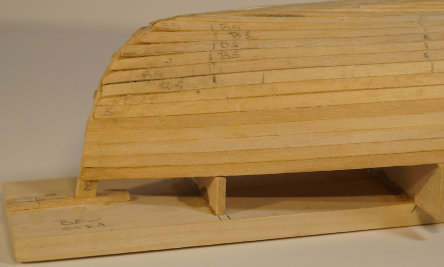
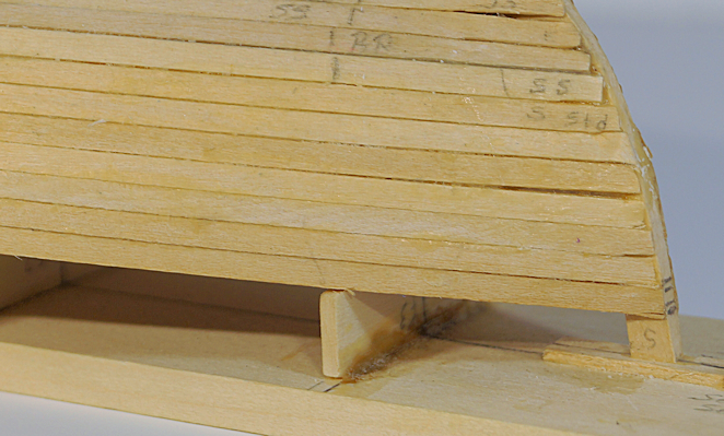
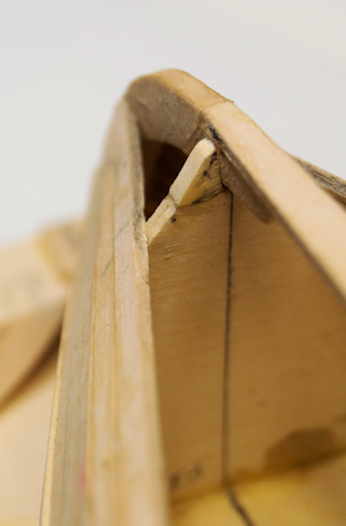
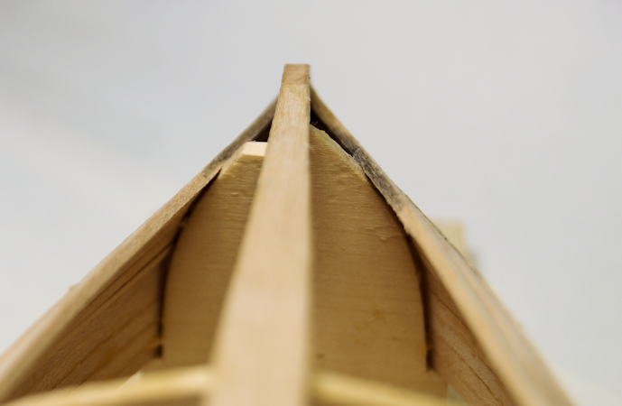
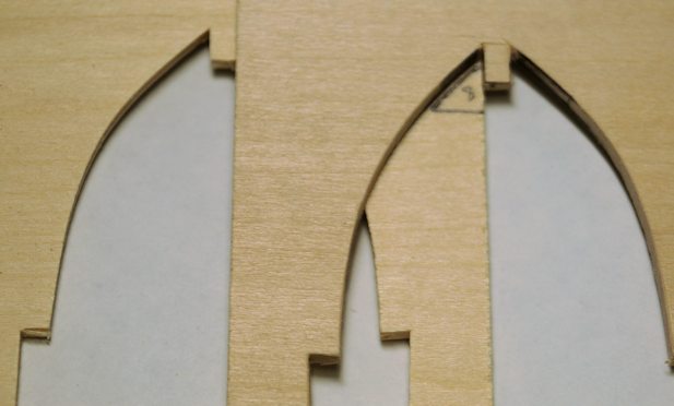
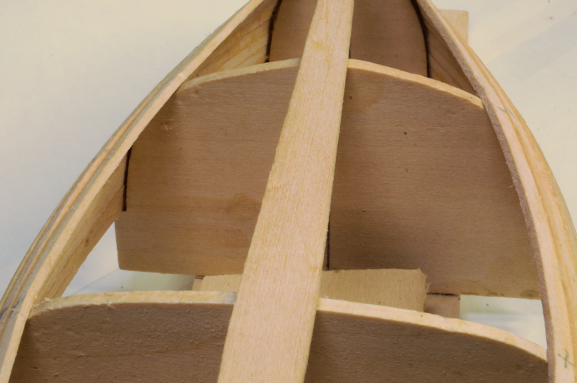
Challenges of model building - and my solutions. Part 2 (and Part 3) These two challenges are related to the bulkheads used for shaping the boat. Part 2: Broken center bulkhead The process for this build is to use the bulkheads and keel pieces as a strong back as described above. The bulkheads provide the necessary shape. Eventually, the boat will be removed from the form. Additionally, the instructions indicate when you remove the boat from the form, the sides may pull inward. The fix for this condition is to remove the center bulkhead from the baseboard and insert that bulkhead back into the boat. When ribs and seats get installed the shape will be held. (A couple of other builds on this specific model indicate this issue does occur.) The removal of the boat from the strong back means you need to be sure the planks don't end up glued to the bulkheads. To aid in this 'glue prevention' problem, I mentioned in a previous post the use of beeswax on the edges of the bulkheads. Also, after I glue a plank in place I flex the bulkheads to check they hadn't inadvertently stuck to the planks. Unfortunately, you run the risk of breaking the bulkheads off of the base board. Which I did...twice. The second time I broke the piece I had a difficult time fitting the piece in place and squaring the bulkhead with the baseboard. The sides of the model don't leave space for this type of work with planks installed. To (hopefully) prevent a third occurrence, I glued pieces of scrap wood on either side of the bulkhead. I took care to leave the smallest of gaps between the scrap wood on the bulkhead so that when I need to remove the bulkhead, I still can. I hope it works because if that bulkhead breaks again, I will not be able to reinstall it. On the good side, I have made the turn from the side to finish the 'bilge' of the boat. With only a few planks left, I shouldn't run into issues. <Keeping fingers crossed, which makes it difficult to assemble parts in place.> Part 3 Breaks on the end bulkheads. I knew this problem would have to be addressed at some point in the build. The end bulkheads at the stem posts came to a point. Early on in the build, those points broke off. Interestingly, the points broke off only on one side of the boat. The last couple of planks on each side need a support near the keel. As you can see in the above image, I am close to that point of the planking. The solution is not that bad. I took the original die-cut form and drew the small pieces I need (about 1/4" roughly triangular). I cut the pieces out and glued them in place with CA (so it would set up quicker than PVA). I shaded the area that I will remove to get the needed shape. It should be a relatively simple matter to sand this small bit of wood. The repaired bulkhead should give the necessary support for shaping the last few planks. After removing the excess wood, I should be able to finish the planking. As a related side bar: To make the strong back, the stems are glued to the baseboard. Having gained experience with using vinegar to loosen the glue, this aspect of loosening the stems should go fairly well.. I'll post images of the finished planking for my next post. Though I will not make any prediction of when that will be since I am not in a hurry.

- 44 replies
-
- 3
-
-
- maine peapod
- peapod
- (and 4 more)
-
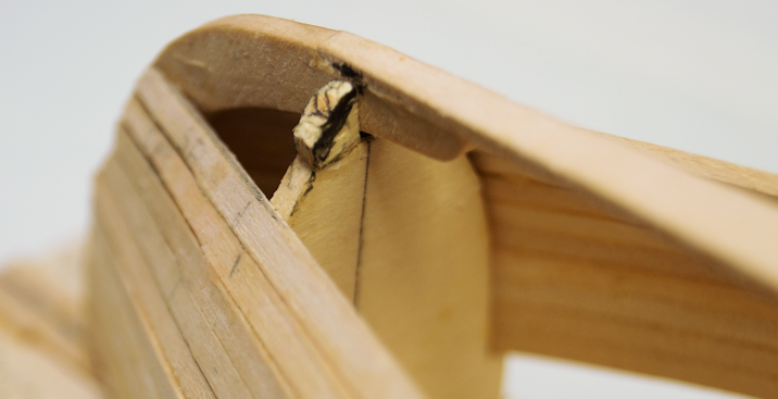
Challenges of model building - and my solutions. Part 1 I decided to write this overdue post to outline a couple of problems I have solved. I didn't realize until I started this topic it has been since April since my last build log entry. However, in my defense I did have some problems with the build. And, of course, real life has uses different priorities just as enjoyable as model building. (OK, a debatable point. But, that's my story and I'm sticking to it.) But I digress. One day after having added a few planks to the hull, I noticed that the last plank didn't fit against the bulkhead tightly. On closer inspection, I found that the problem started with the previous three planks. The gap was getting wider with each additional plank While the matter was more prominent on one side, both sides of the boat had the issue. I either didn't bevel the planks enough or I didn't hold the planks in place tight enough while the glue was drying. Most likely a bit of both. The errant plank was nearly 1/8" out from the bulkhead. (See the first image in above post 6 to get an idea of what that might look like.) Challenge #1: Remove planks to correct a problem. How does one correct that? I determined the best fix would be remove the errant planks and redo them. I searched MSW, other modeling sites, and general wood working sites to find how to disassemble wood joints held with carpenter's glue (a.k.a. PVA). The three methods were apply fairly high heat to loosen the join, or use acetone or vinegar soften the glue and allow removal of the plank. Since the area I wanted to affect was fairly narrow. I didn't want to risk using high heat as it would likely warm up all planks. I am not a fan of acetone because of the smell. (I know, not bad, but still bothersome to me.) So, I went with the use of vinegar. I applied the vinegar with cotton swaps removing one plank at a time on each side of the model which reverses the assembly process. In a couple of cases I had to wait 15 to 30 minutes for the glue to soften the glue. However, vinegar did soften the glue and I could pry the planks apart. I started at one end of a plank and worked towards the center bulkhead. I then worked on the other end of the boat to center and repeated the process. The process went well until I got to the fourth plank. And then...Whoops! (OK, I used a few other stronger words at the time. 🤬 😭 ) Capillary action along the port bow stem soaked all the end joints. As I pried the plank I wanted to remove, all the planks came loose from the stem. BTW, for the photo, I did hold these out a bit to show the issue very clearly. On the good side I found out three things. 1. White vinegar, full strength, does soften carpenter's glue and with care you can loosen each plank as needed. 2. Though the vinegar softened the glue, it appears that after the vinegar dries/evaporates, adjacent joins do not seem to be effected. 3. With a bit of sanding to smooth the stem and plank end the above was corrected with little problems. The other lesson I learned was to be sure take a bit more care when beveling and fitting the planks. As with many challenges, you can improve your process. As you can see, I think I have solved the problem. So, on to the next challenge.

- 44 replies
-
- 2
-
-
- maine peapod
- peapod
- (and 4 more)
-
Looks like a neat little build. Looks great so far. I look forward to watching the progress. You may want to use the sail material provided. It's hard to tell from the photo with the box cover how the sail looks on the finished model. If the material is silk span (a tissue thin material), most techniques use layers to make the sails. Also, most sails are made from panels that can be simulated by overlapping the silkspan. At 1/10 scale, you can get by with thicker material that will look to scale. For me, I'd look at what the instructions show. As for 'schwertkasten' translation, I'd say it's a keel trunk or keel box, which probably doesn't translate well to German. The English term for item that goes into the box is "centerboard," though keel works well enough for descriptive purposes. Good luck on the build.
- 16 replies
-
- 1
-
-
- Optimist Dinghy
- optimist
- (and 2 more)
-
Glad to have provided a bit of inspiration. As update...RL has gotten in the way. As I mentioned a previously, I ran into an issue and had to remove some planks. However, I have corrected that problem plus one other that cropped up (or broke down - as the case may be). I am putting more effort into making time for the workbench.
- 44 replies
-
- 2
-
-
- maine peapod
- peapod
- (and 4 more)
-
Coming along very nicely.
-
Help with these clamps
robert952 replied to Some Idea's topic in Modeling tools and Workshop Equipment
Hmm, maybe even easier than that @Mic_Nao Looks like a countersunk head machine screw used. Solder a matching nut on the end of the screw in lieu of a handle. Brass bar stock instead of aluminum plate? -
I just had an 'I wonder' thought... How much will this model weigh when it's complete? (And then the follow up question: Where will it be displayed?
-
Great build that can inspire others to expand their abilities and skill sets.
- 62 replies
-
- 2
-

-
-
- First Build
- Grand Banks Dory
- (and 2 more)
-
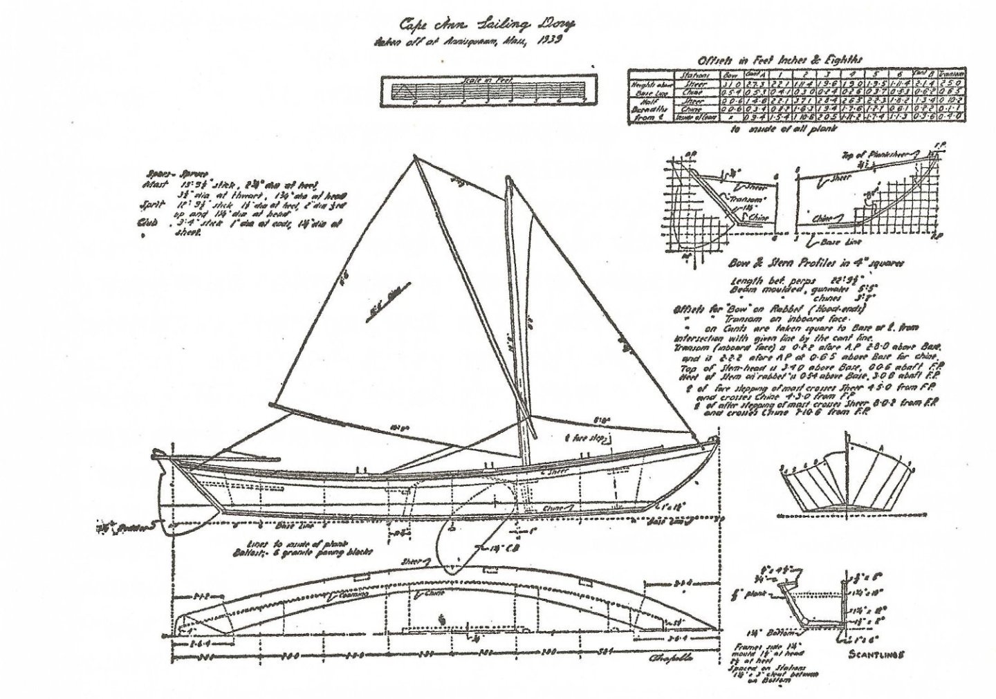
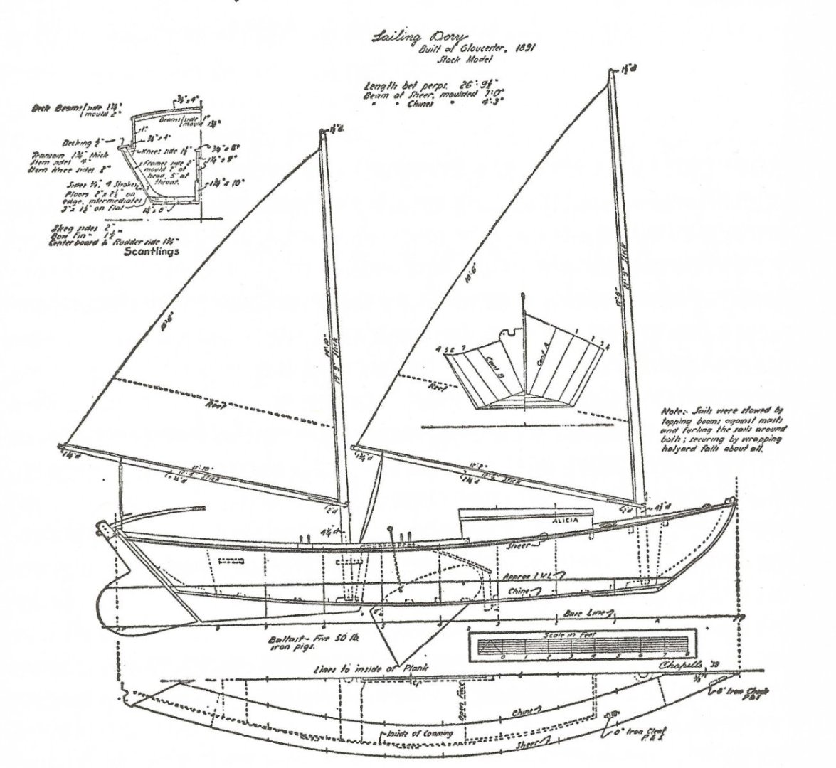
You are quite welcome. Glad to help. To your comment about stepping the mast when needed, there's a note on the two-masted sketch describing how to store the mast and sails. Necessity is indeed the Mother of Invention. I think Chappelle just collected the drawings and pulled them together for his books. He then commented on the "whys and wherefores." I like going through this book as it shows variations that were done to meet specific tasks or unique needs based on locale. As you point out, adding a sail seems a good way to get your feet wet on scratch build aspects. Hence, why I plan to add a keel, rudder and sail to a 'kit build.' A lot of these work boats included a sail to otherwise traditional row boats. As you found, there's photos which documents such changes.
- 62 replies
-
- 3
-
-
- First Build
- Grand Banks Dory
- (and 2 more)
-
Here are the scans. The print on the original page appears smudged. But you can use the scale on the page to get a decent approximation for the size of the sails. With one mast. NOTE: If you look at the position of the mast it appears to be in the second thwart. Likely because the jib covers the first thwart and attaches at the bow. So, it may be a genetic aberration? Evolution has a way of changing things and no single example is the exact way things were always done. You are as likely to have done it correctly as the any other model. And the two-mast version. Again, both of these examples have rudder and center board. If you down load these and they have gotten resized, PM me an email address and I will send them to you. I scanned them at 600 dpi to give as much detail as possible. Source for these are: American Small Sailing Craft by Howard, L. Chapelle copyright 1951 by WW Norton and Company. Pages 91 (top image) and 93. (bottom image).
- 62 replies
-
- 2
-
-
-
- First Build
- Grand Banks Dory
- (and 2 more)