

robert952
-
Posts
922 -
Joined
-
Last visited
Content Type
Profiles
Forums
Gallery
Events
Everything posted by robert952
-
 I just posted this same observation in another log...modelers always figure a solution the problems that arise. Agree with Ross and Hamilton, nice looking repair job.
 -
Looks like necessity was mothering another 'invention.' I assume the saw served as a counter weight to the clamps, correct? Modelers always find a way to solve a problem.
-
Continues to look great. Did you paint the rings or blacken them chemically?
-
Definitely a change of pace for a build. Looks interesting.
-
Nice looking color scheme.
-
Nice looking lines! Great job on that 90 degree bend on the planks.
-
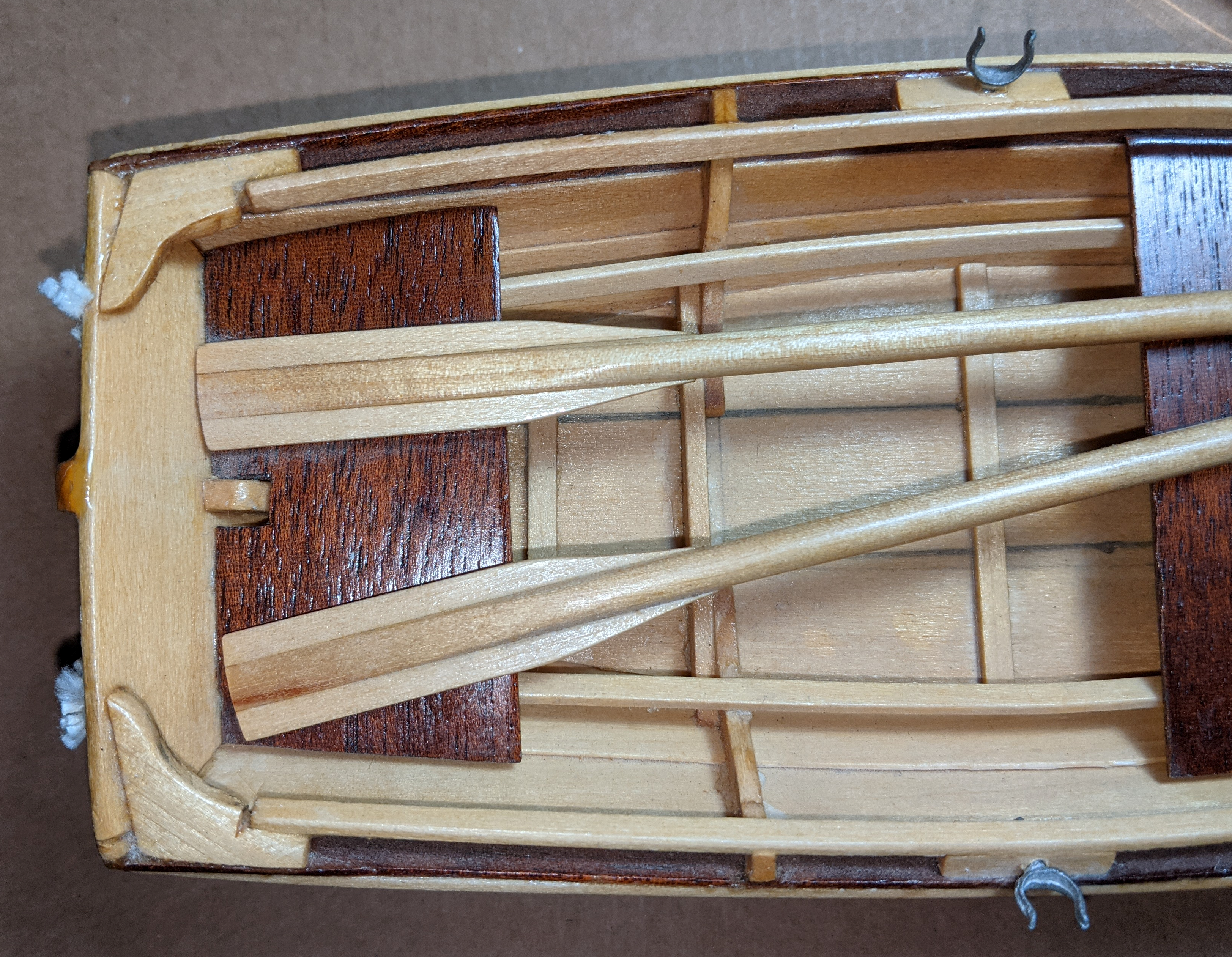
Thanks for sharing your experience, James. I haven't been discouraged by the kit. Frustrated, yes. But for me that's part of the learning process. One goal I set was to learn how to apply planks to a model. I agree, making complex bends proved challenging. (A few planks had to be redone during the process.) I think I accomplished the task adequately and reached my learning goal. Once I made the turn towards the keel, the process became easier and relied more on trimming the planks over bending them. And your points of filling and sanding are spot on. The lines of the boat make sanding the interior (particularly) difficult. I think the kit does a good job providing learning opportunities for the beginner. The kit also gives room to modify and differentiate the model. My adding a keel and sail will be my contribution to the changing the kit. I guess that shows the different experiences we have had with the model. I am not trying to discount the technique the image shows for that prototype. The image obviously shows an approach for constructing these boats. I found the images below of a peapod under construction at this site: Soundings. (Original article published in June 2021) It appears there's multiple ways for building a peapod using different planking techniques. My opinion is that the small planks are an accurate method for some peapods. Side Bar: It's hard to believe my last post in this thread was October! However, I do see a light (dim as it is) at the end of the tunnel. Our physical move should be completed by mid-January. I hope get back to this model in February/March. (Part of that time frame depends on my ability to find all my tools and modeling stuff we packed for the move. 🥴 ) I am glad I decided to focus on the move over attempting to continue work on the model. Between getting my house ready to sell and keeping track of the construction of the new home, I have had little spare time. That situation would have been discouraging. However, the time to focus on my modeling is approaching.
- 44 replies
-
- 3
-

-
- maine peapod
- peapod
- (and 4 more)
-
The evolution and design details of small boats shows a lot of opportunity to model even small boats more accurately. I have been leaning towards the smaller craft as I build my skill sets and research reading. If I recall, Howard Chapelle's American Small Sailing Craft addressed a section on dories. (My library is packed and in temporary storage, so I can't verify that fact.) He discusses both versions of boats with and without sails. A lot of small craft was 'customized' for specific roles and locales. I find what you describe on the dory very interesting info on this construction. I'll have to take another read through my copy.
-
Off to a good start! Following along on this build.
-
@Diver Short answer, yes, thin the paints for airbrushing. You might want to check out this thread: LINK Bob Cleek (along with many others) has a lot of good info to share in the linked thread. Test paint the material and various ratios of water to paint to see what give the best results.
-
Following along. As you point out, there's several other logs for this half-hull. Yours is shaping up to be a good one to bookmark. Sound processes you are using to solve the problems.
-
Every model is a learning experience. And each model is an improvement of the last one. Looking forward to our next build. Congrats on a nice looking model.
-
My thanks to all who shared. I will mention something that may be obvious. But I have been know to overlook the obvious. Lots of light and probably magnification. Hard to reach usually means hard to see. So, I suggest a lighted magnifier on an articulated arm. Due to work space limits, this may or may not work. Alternatively, a head band with lights (with or without magnifiers) are one of those love/hate relations with me. Weight and comfort the big problems in my opinion. However, I was helping my son with a home project a couple of days ago. He had a couple of LED headband lights that amazed me with their brightness. (Bright enough to easily watch the operation of a dryer vent 25 feet up in the dark. It wasn't dark when we started the project.) They were similar to this: Home Depot link to product. (There's other sources and variations on rechargeable, brightness modes, etc. I'd bet there's a magnifier headband with super bright LEDs.) The one he had was magnetic and attached to the head band or could be placed on metal surface. It was very lightweight. I am rethinking the headband approach alternative.
-
Me, too. Following along to see what the more experienced folks have to say.
-
Glad to see you back in the shipyard. Sorry to hear about your getting injured but glad all is well now.
-
Based on your work with the Dory and how it looks, either of the rereleased models will be easy enough and give you a learning experience. I wonder if Model Shipways are true rereleases or did they do any changes. (Not that there's a lot needed.) I also have some of the older MW models in my stash I may build...one day. I am not sure why the two different skill levels. I built the dinghy. It is a good basic model, minimal tools required. Maybe even easier than the dory you just finished. If I were to build it again, I'd tweak how the rope work was done to make it a bit more 'real looking' with proper binding. I think that would add a bit of challenge to add that touch. Good luck. I look forward to the build logs on these.
- 19 replies
-
- 1
-
-
- Grand Banks Dory
- Model Shipways
- (and 3 more)
-
I am gaining an affinity for these smaller boat models. Look forward to seeing this build.
- 31 replies
-
- 4
-
-
- Lowell Grand Banks Dory
- Model Shipways
- (and 1 more)
-
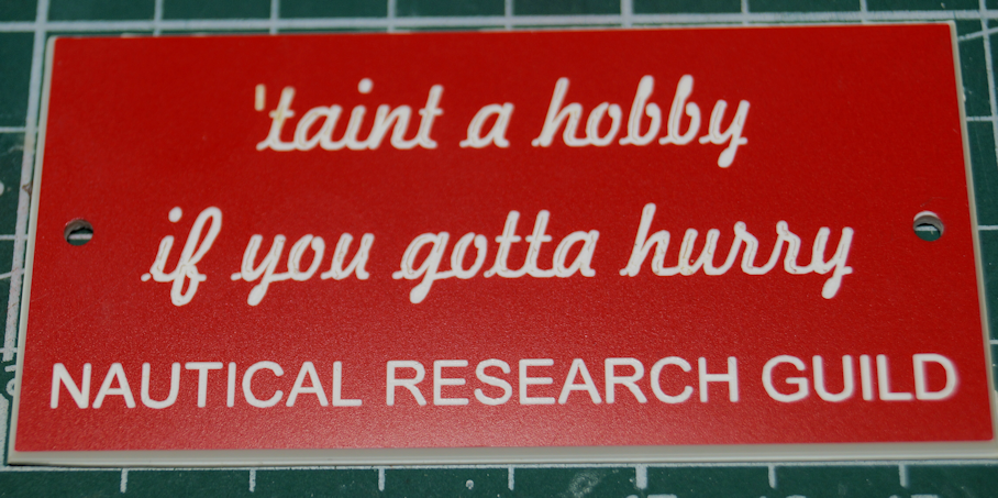
Great point. As the sign says:
-
Shot Garlands
robert952 replied to tmj's topic in Discussion for a Ship's Deck Furniture, Guns, boats and other Fittings
A great thread for those (like @tmj and me) can learn details. I appreciate the time all took to post an answer. -
Hopping on board for this build. Looks good. From what I have gleaned from this model, it is a great entry model and you will do fine with its assembly. If you want assistance in the way of techniques or problem solving, ask away. Most of us will do our best to help you along the way.
-
I thought I had marked to follow this one. I have now. Nice job so far. Looking forward to watching the build.
-
You might find this video useful. Making Sails for Ship Models from Silkspan, Part 3
-
Quick update on this build. Likely not going to do much for next few months. Possibly some sanding and filling in the garage). We are in the middle of changing residences. (That's the simple description.) New house being built - schedule closing early next year. Keeping track, will make a few trips to keep track of progress - 3 hour drive from current home. Also, will be 'staging' our belongings to a U-Stor-It type place. Getting current home ready for market. Goes live late this month/early November - should sell quickly as I did a lot of upgrades and the market here is still a hot seller's market Starting to pack stuff up so that the house looks like no one really lives here. Mostly just 'declutter stuff.' But that includes my modeling desk per the real estate agent. This is also called 'staging.' (Maybe I should post in 'Play on Words.)
- 44 replies
-
- 2
-
-
- maine peapod
- peapod
- (and 4 more)
-
Planking Book?
robert952 replied to BWDChris's topic in Building, Framing, Planking and plating a ships hull and deck
@Paul Le Wol I feel I need to point out: syrenmodelshipcompany.com is incorrect. The correct URL is this link syrenshipmodelcompany.com To go straight to the monographs click here: HMS Winchelsea 1764.
