Dr PR
-
Posts
1,491 -
Joined
-
Last visited
Content Type
Profiles
Forums
Gallery
Events
Everything posted by Dr PR
-
 I haven't used TurboCAD in years, but I have used it's sister program DesignCAD since 1988. I can think of several ways to achieve what you want to do. Pick the one that you are more comfortable with and that your version of TurboCAD will allow: 1. You can use a version of wrkempson's suggestion. 1A. Create a "surrounding solid" with a cannon barrel shaped hole in it that has a diameter larger than the canon barrel that is equal to 2x the height you want for the insignia extrusion (a radius with 1x the height). Be sure the axis of the hole is contiguous with the axis of the cannon barrel. One way to do this is to make a copy of the cannon and subtract it from a surrounding solid - this gives the proper hole shape in the solid. Then scale the surrounding solid so the hole diameter is larger than the cannon barrel by the desired amount. 1B. Make the insignia extrusion several times as high as you want it and position it so it extends into the cannon barrel as well as into the surrounding solid. 1C. Subtract the surrounding solid from the insignia extrusion. This will produce the desired outer curved surface for the insignia. 1D. Make a copy of the cannon barrel and subtract it from the insignia extrusion to get the proper inside curved surface. OR Just "solid add" the insignia extrusion to the cannon barrel to get a single solid - what you need for 3D printing. 2. Another way to get the desired curved insignia extrusion is to use your original insignia extrusion to create a curved surface on the cannon barrel, and then extrude it. 2A1. Find the intersection of the insignia and cannon barrel. This will be an outline of the insignia on the barrel surface. 2A2. Convert this outline to a surface. 2A3. Extrude the curved surface to the desired height. OR 2B1. Make a copy of the cannon barrel and subtract it from the insignia extrusion. 2B2. Explode the insignia extrusion solid and eliminate all parts except the lower surface contiguous with the surface of the cannon barrel. 2B3. Extrude the lower surface by the desired height. Phil
 -
That's all for now. Someday I will create a 3D model of the Kaman SH-2B Seasprite helo that the ship carried, but right now I do not have very good drawings and dimensions to work from. The next step it to start creating the plans for the actual 1:96 scale model. Phil
- 48 replies
-
- 2
-

-
- 3d cad
- cleveland class
- (and 1 more)
-
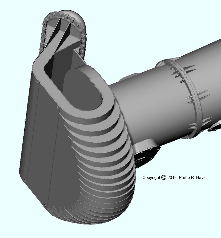
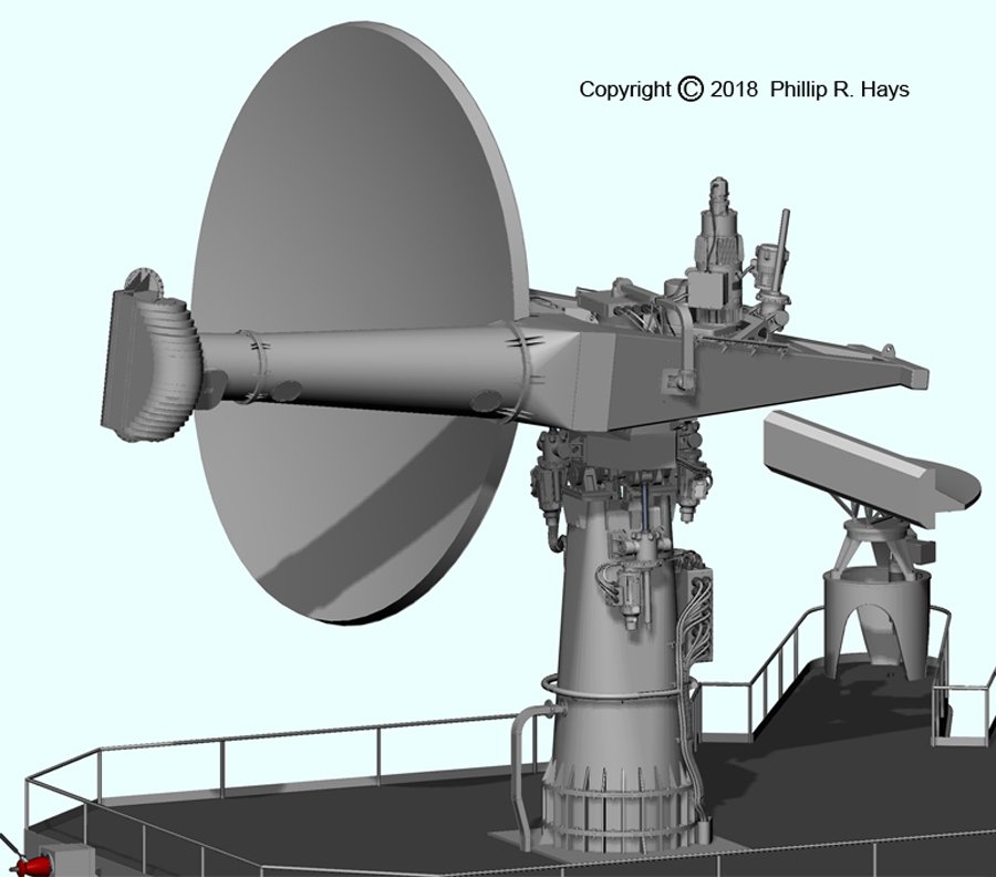
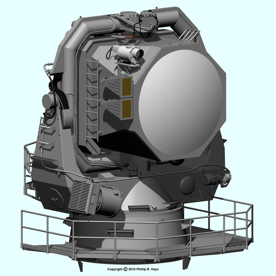
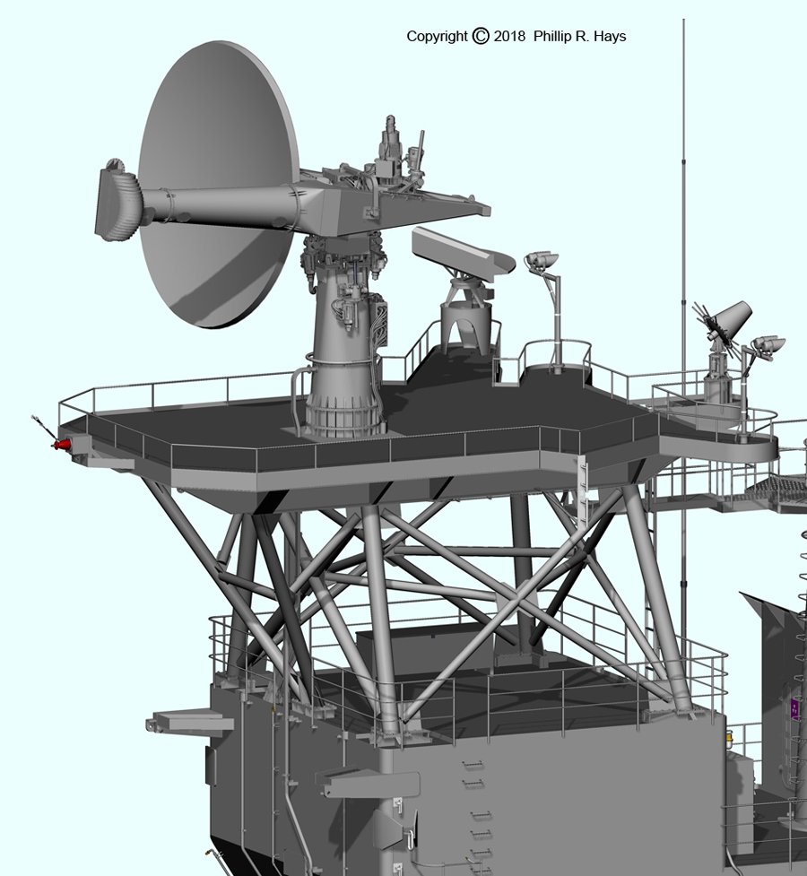
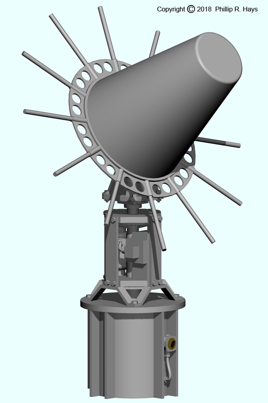
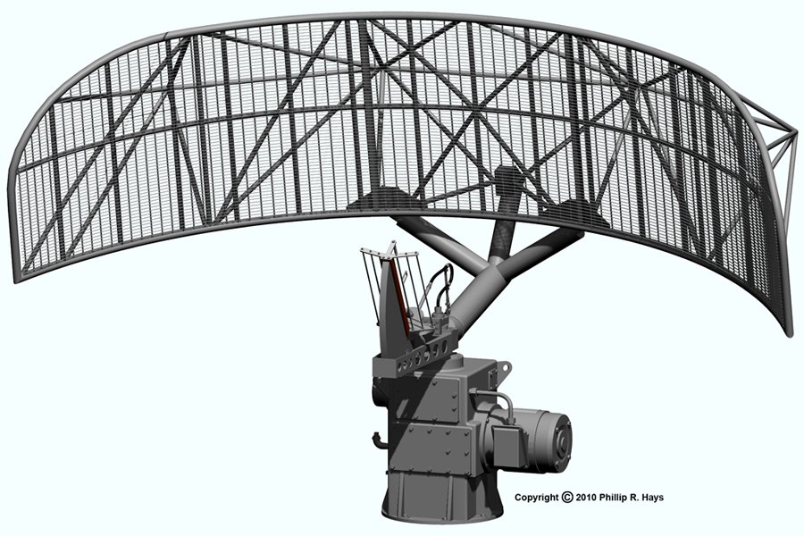
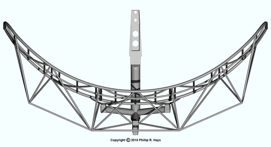
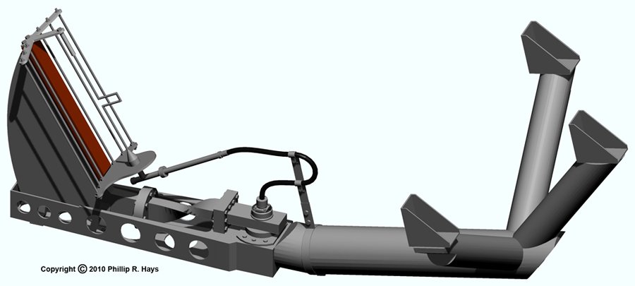
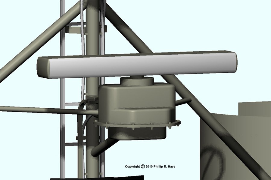
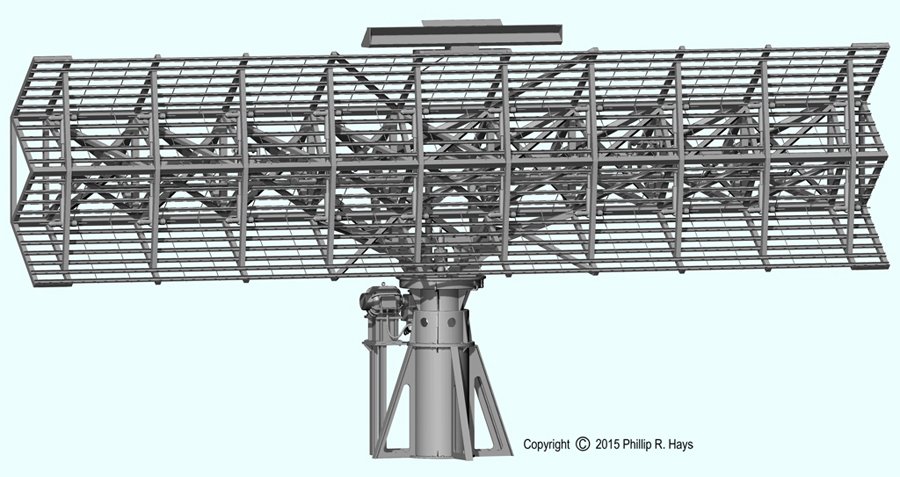
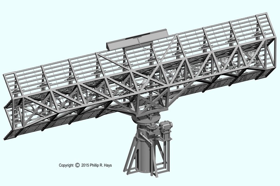
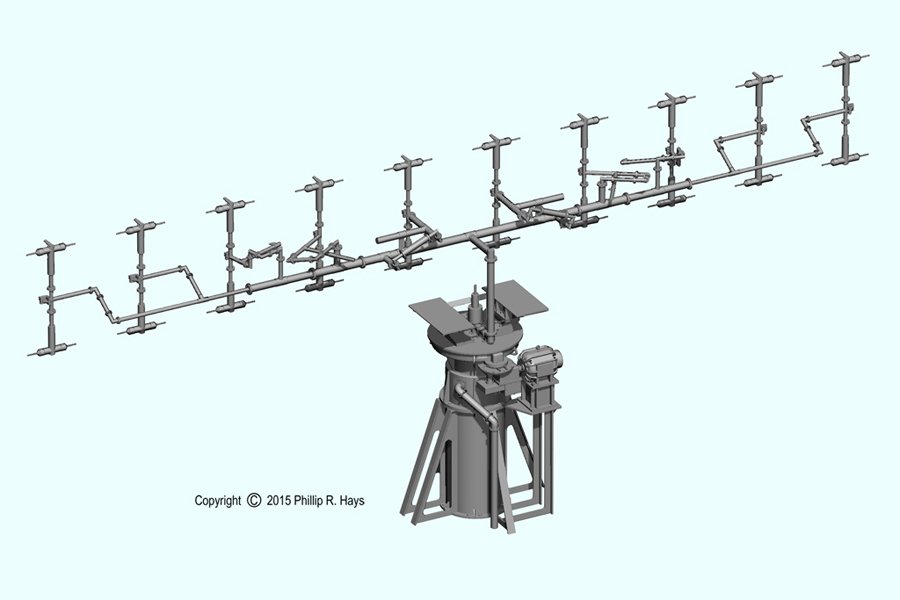
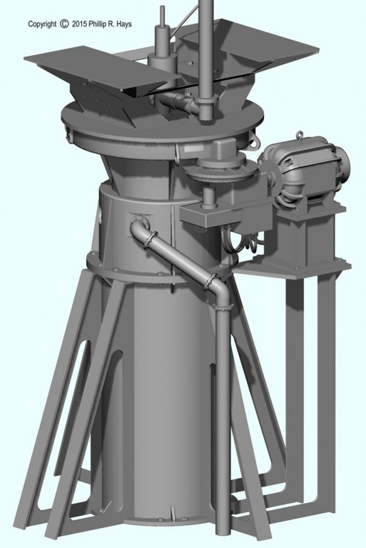
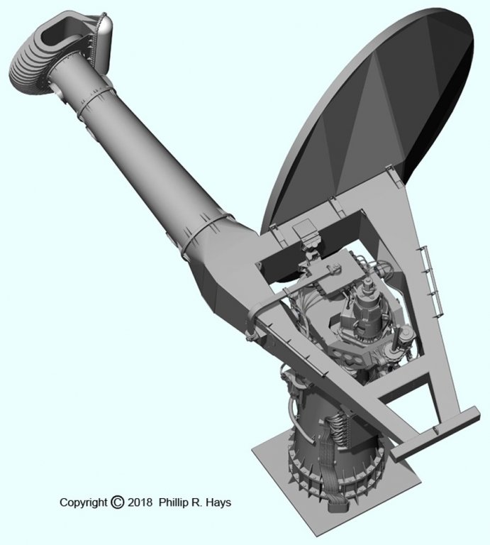
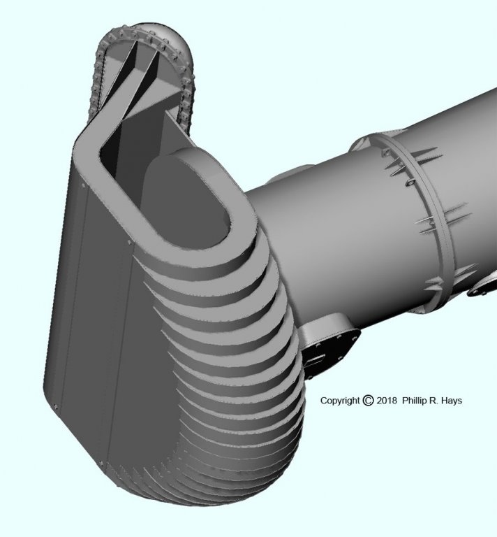
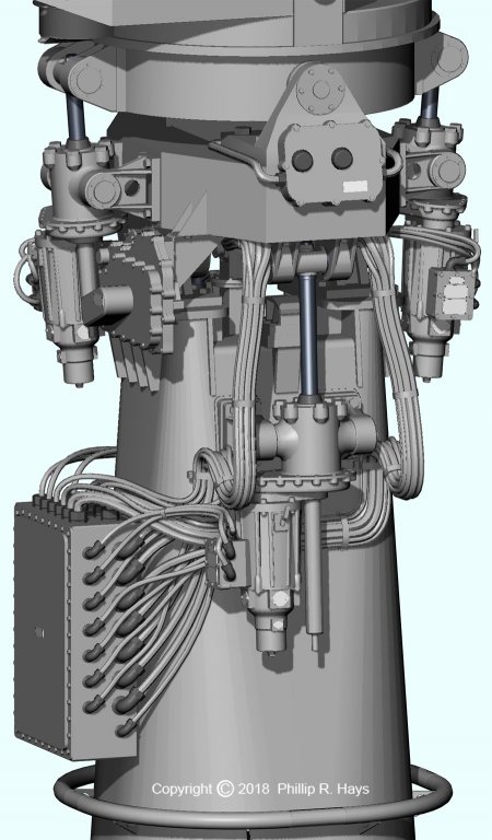
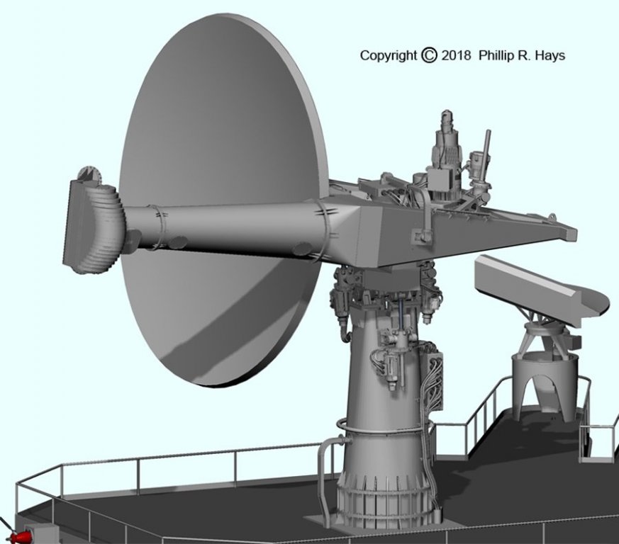
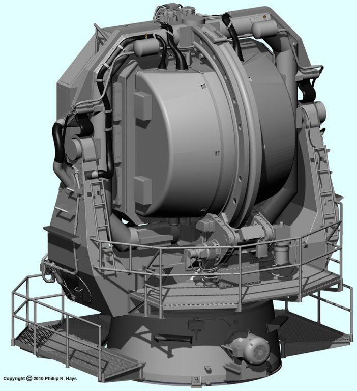
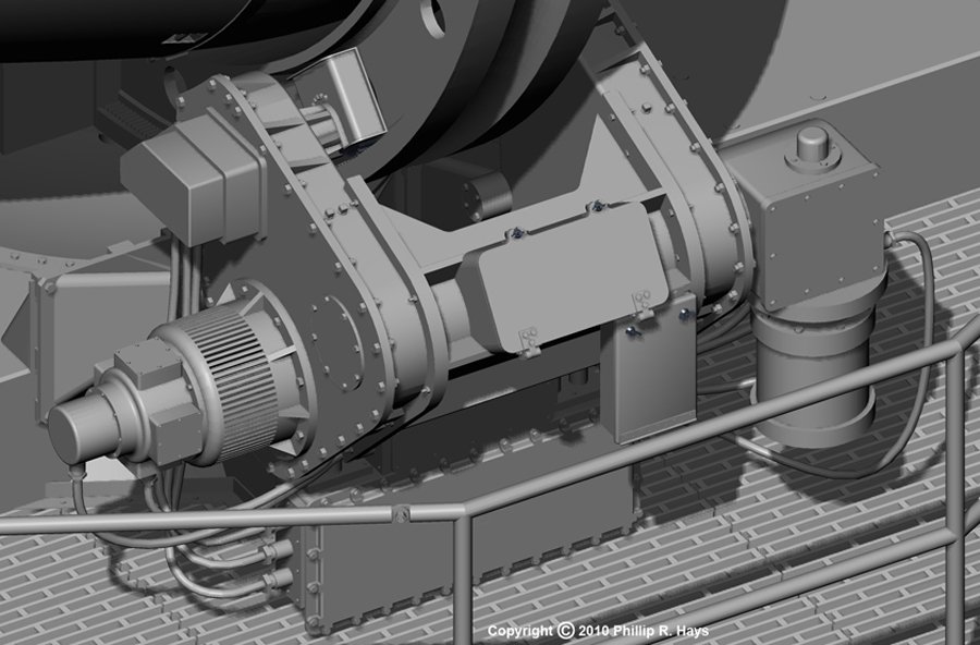
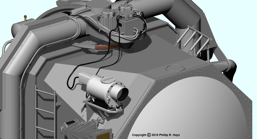
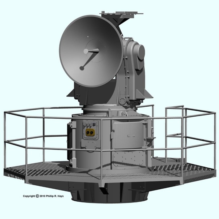
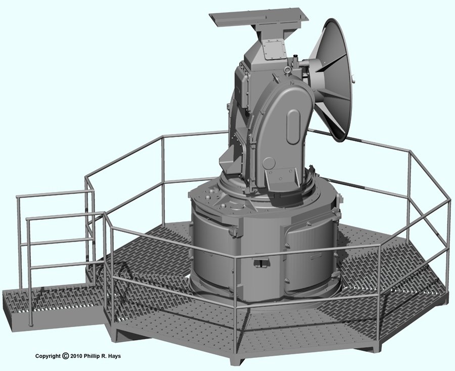
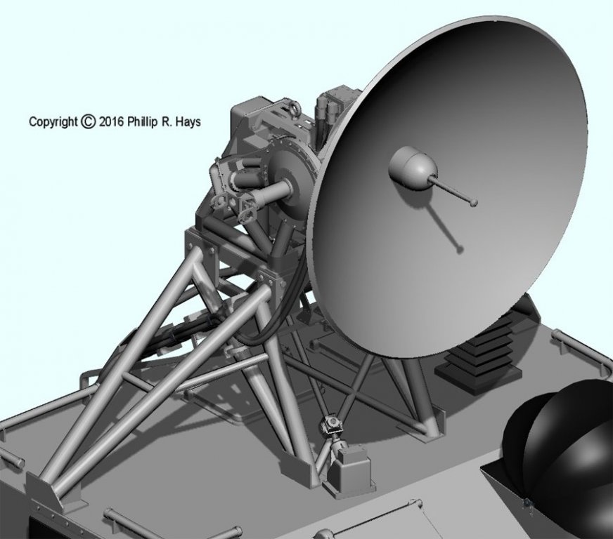
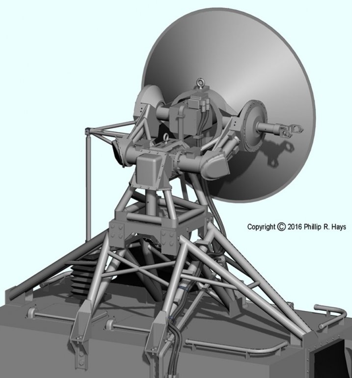
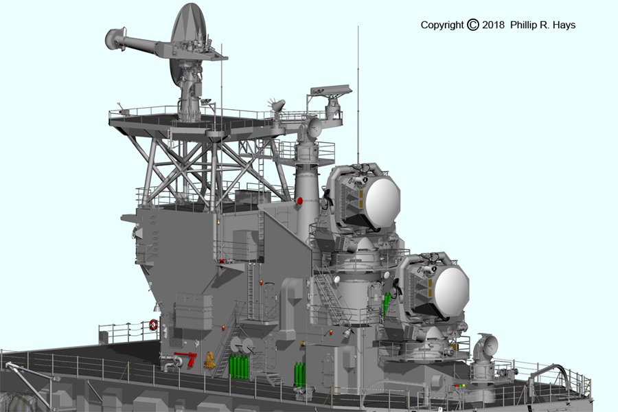
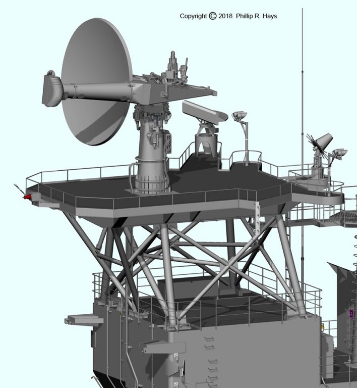
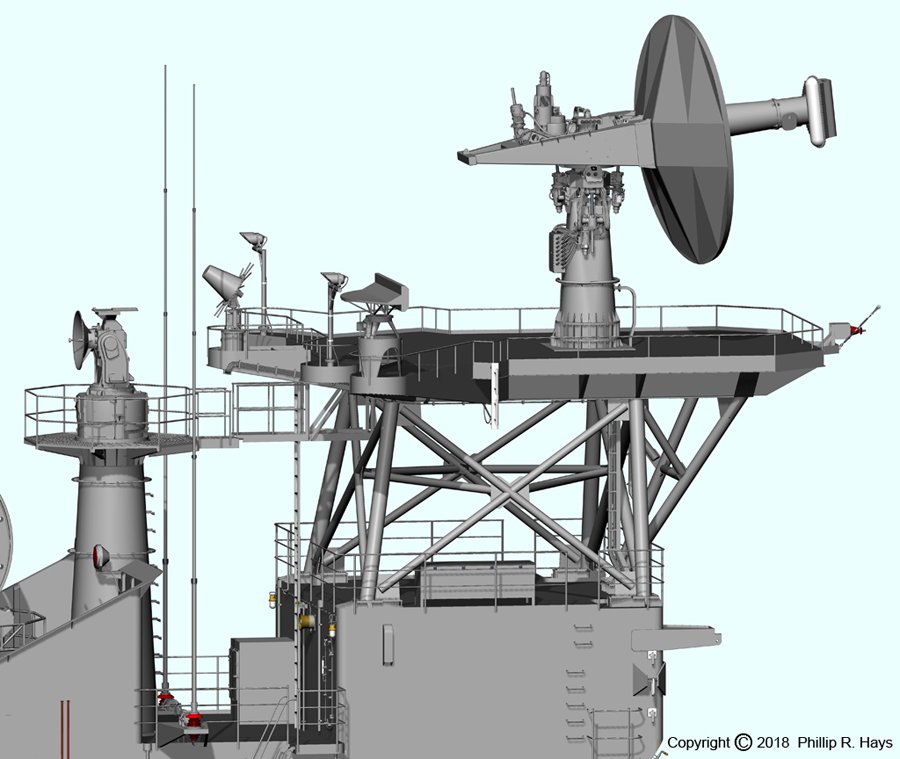
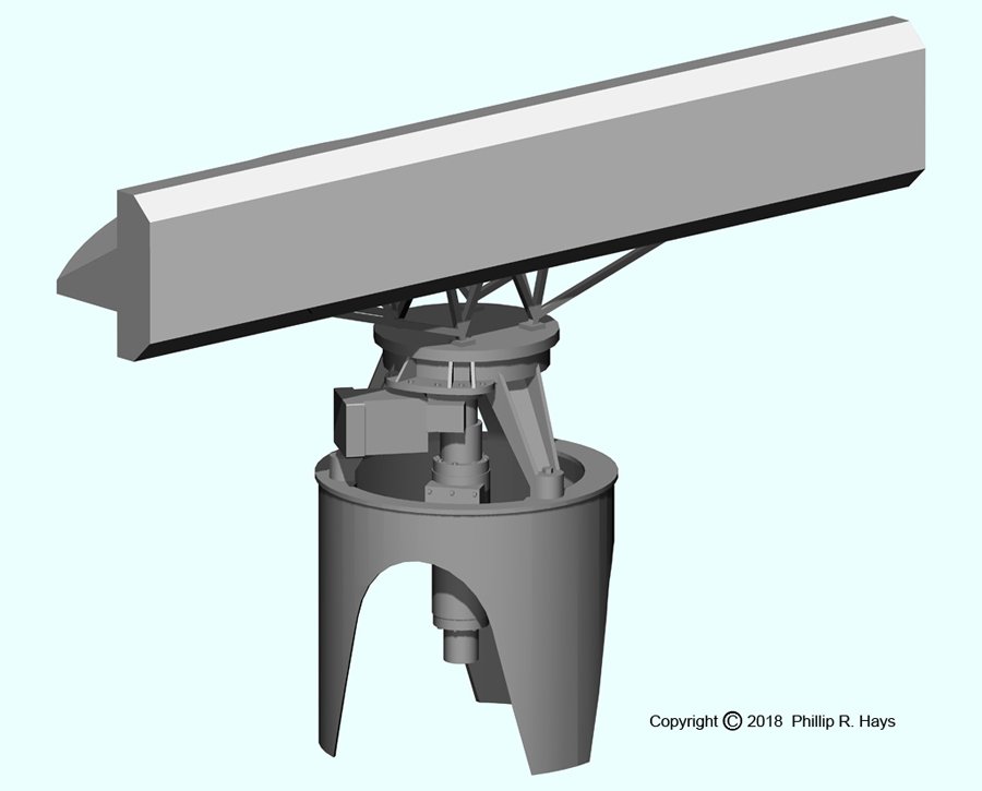
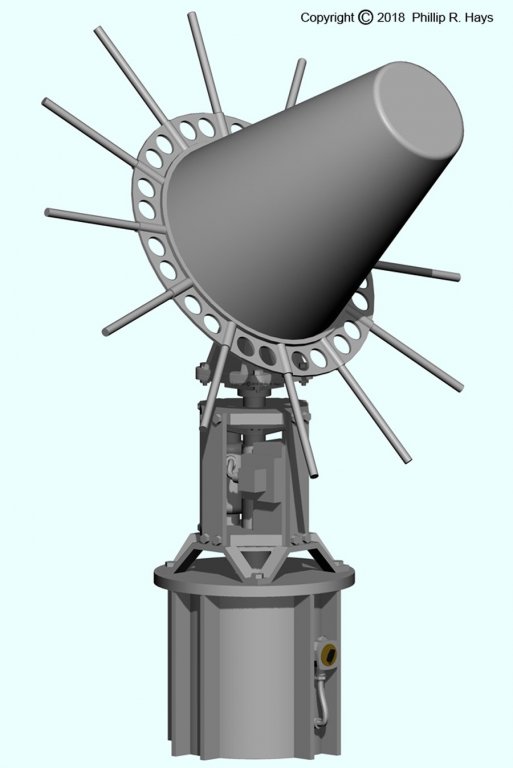
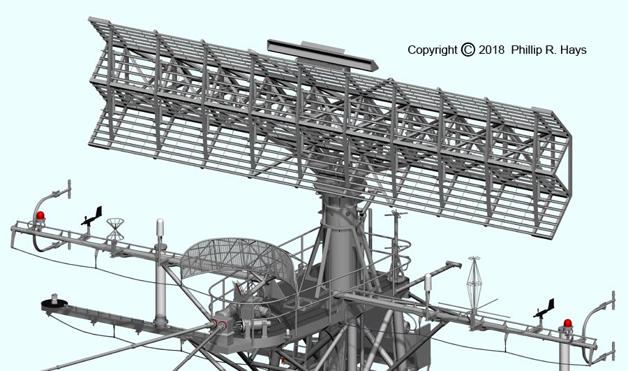
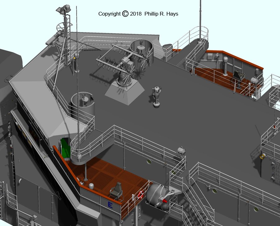
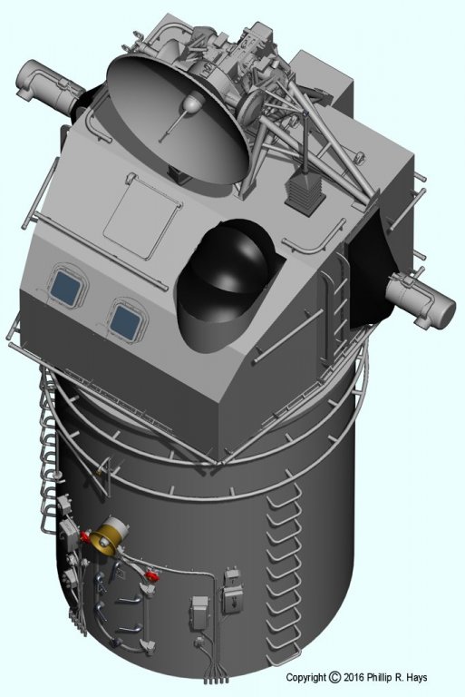
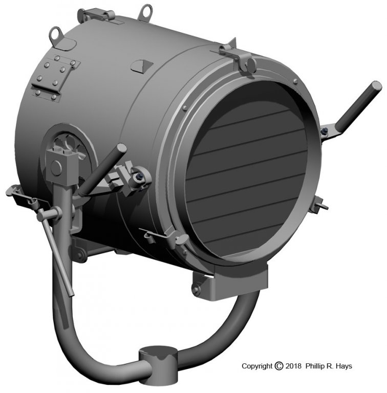
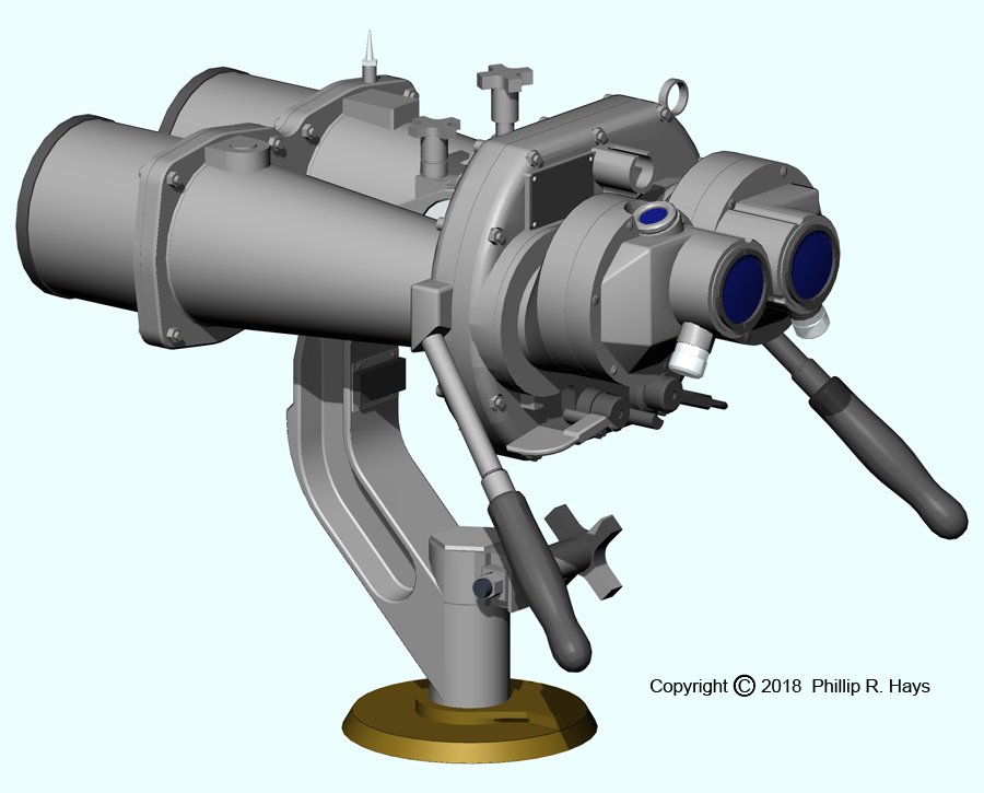
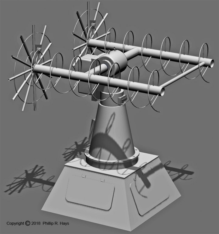
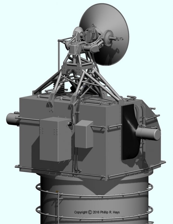
RADARS The ship carried a collection of radars. I have data sheets and drawings for most of them, and the service manual for the AN/SPS-10. Each antenna was a model unto itself. AN/SPS-10 Surface Search Radar The SPS-10 was the primary surface search radar, used to detect ships and low flying aircraft and missiles. On the OK City the horizon was about 13 miles at the height of the SPS-10 antenna. The radar could track targets above the horizon out to about 100 miles. It was very sensitive when tuned properly. On one occasion we tracked flocks of birds a mile or two away. On another occasion when we had excellent atmospheric "tunneling" over the horizon I tracked an aircraft carrier at Yankee Station in the Gulf of Tonkin at a distance of 65 miles. The SPS-10 operated at 5.42 to 5.825 GHz with a 285 kW peak power. The antenna carried a AN/UPX-27 Identification Friend or Foe (IFF) dipole on the "spider" arm that held the feed horn. This is the rod with the square kink in it, and the surrounding reflector rods. Pathfinder Navigation Radar We had a Raytheon Pathfinder radar for navigation in harbors and channels. The SPS-10 had a minimum range of about a mile or so, and couldn't detect close in objects. The Pathfinder was good down to very short distances. This is a very sketchy illustration. I have no data sheets or drawings and only a few fuzzy photos to work from. Some day I will have better information and will be able to make a more accurate model. AN/SPS-43 Air Search Radar The SPS-43 was the primary air search radar. It had an effective range out to 300 miles for high flying planes and missiles. The minimum range for low flying planes was limited by the horizon. In Vietnam I used the 43 to track B-52 flights from Thailand to targets in North Vietnam. The huge slab sides of the B-52 were "anti-stealth" - they showed up as large bright blips on the radar screen. They were called "Arc Light" missions for good reason! The "bed spring" reflector had a "W" shape cross section behind an array of ten pairs of dipole antennas fed by a complex coaxial transmission line system with power dividers to feed each pair of dipoles the same amount of radiated power. The SPS-43 operated in the VHF band at 200 MHz with 180 kW peak output. I finally found a few high resolution photos to allow me to work out the details of the antenna and support pedestal. The short rectangular antenna at the top is an AT-352/UPA-22 IFF Interrogator antenna. AN/SPS-30 3D Height Finder Radar The SPS-30 was an air search radar that had altitude detection capabilities. Altitude information from the 30 was fed into the missile guidance computers for intercept calculations. The SPS-30 also served as a secondary air search radar. An AS-791/UPA-43 IFF Interrogator antenna located on the aft radar tower platform was slaved to the SPS-30. The SPS-30 had a large oval parabolic dish reflector. In front of the reflector, at the end of the long support arm, was an "organ pipe" scanner. A waveguide connection in the scanner rotating at 240 to 2400 RPM fed the RF energy into twenty parallel vertically stacked waveguides leading to the feedhorns. Each feedhorn radiated RF energy at a slightly different angle to the reflector, resulting in 20 different beams reflected at different elevations. Returning signals from a target reflected off the dish into the respective feed horn, allowing the system to determine the vertical angle from the antenna to the target. From this angle and the range to the target the elevation was calculated. The antenna could be rotated for air search operation or it could be aimed to track a single target. The entire rotating antenna dish and support arm could be elevated to track targets through a wide range of elevations. The mechanisms of the antenna were supported on a pedestal that had a gimbal system to compensate for roll and pitch of the ship to keep the antenna aimed at the target being tracked. Dual electric motors positioned the antenna for roll and pitch compensation. The SPS-30 operated in the S band from 3.4 to 3.6 GHz with a peak output power of 2.5 megawatts. It had an effective range of 240 miles. AN/SPG-49 Missile Tracking Radar The ship carried two SPG-49 tracking radars. The SPG-49 was a 19 feet high, 17 feet wide, 22 ton monster. The 49s had C band monopulse tracking radars and continuous wave (CW) illumination radars combined into the one antenna. The system performed three functions. During target acquisition the antenna radiated 3 megawatt pulsed bearing and azimuth sweeps to determine range, bearing and altitude of a target. After the target had been acquired the antenna switched to a pulsed 3 megawatt narrow beam tracking radar. When a missile closed range to a target the antenna also radiated a 5 kilowatt CW illumination beam that carried target identification information for the missile to home on. All of the transmitters and receivers were housed inside the antenna shell. The mechanism consisted of four assemblies. The truncated cone base was mounted on the ship with an accuracy of +/- 0.035 inch vertical relative to the axis of the missile launching system. The base contained a hydraulic drive to rotate the "U" shaped yoke around the vertical axis on the base. The yoke carried dual electric motors to drive the gimbal that rotated around the horizontal axis. The antenna housing rotated around the vertical relative to the gimbal by two sets of dual electric drive motors. A coarse bearing was maintained by the rotation of the yoke, but the motors on the gimbal allowed the antenna housing to be rotated side to side quickly and with better precision. The antenna carried a closed circuit television camera that was used for antenna alignment. It could also be used to track short range targets visually. The Talos missile had a range of 130 nmi and the SPG-49 had a maximum range of 150 nmi. Tracking information from the 49s fed the missile guidance computer for calculation of the intercept position. For more details of the SPG-49 construction and operation use this link: https://www.okieboat.com/SPG-49 description.html AN/SPW-2 Missile Guidance Radar The ship carried two SPW-2 "radars." The SPW-2 wasn't exactly a radar. It transmitted a narrow guidance beam that the beam riding Talos missile followed. The missile guidance computer calculated an intercept point ahead of the target position and used the SPW-2 to drive the missile to the intercept point. The missile transmitted position and identification signals that the SPW-2 received. The received signals from the missile fed the guidance computer to track the missile. The SPW-2 had a small optical telescope that was used for alignment. It also had a platform on top that could carry a closed circuit television camera, but we didn't have the TV cameras on the SPW-2s while I was aboard. The television camera could be used for alignment and to visually track the missile in flight at close range. Mk 25 Gun Fire Control Radar The Mk 25 electronics were housed in the Mk 37 gun director, with the antenna on top. It was used to determine bearing, elevation and range to targets that were engaged with gunfire. For direct fire missions with visible targets it tracked the target. For indirect fire missions with targets hidden behind hills it tracked a known point on land for reference in calculating the range and bearing to the target. The Mk 25 operated from 5.2 to 10.9 GHz with a peak power output of 50 KW. It could track targets out to 50 nmi. Phil

- 48 replies
-
- 5
-
-
- 3d cad
- cleveland class
- (and 1 more)
-
Best Software for Deck Plank Design?
Dr PR replied to knightyo's topic in CAD and 3D Modelling/Drafting Plans with Software
Jaager has a good point. You can't take a flat print and map it directly onto a curved surface. That's where 3D modelling has it's virtues. However, going from a 3D model and "flattening" it onto a 2D print is a VERY complex operation. Many (most) CAD programs cannot do this (one of the members of the DesignCAD Forum wrote a macro that will flatten designs, but creating the design so it will flatten correctly is still tricky). Programs designed for sheet metal stamping can open up 3D designs for cutting out of flat metal sheets, but those programs usually aren't design programs. Having said this, I doubt that the deck camber is significant enough to cause problems going from a 2D design. You can measure the deck width midships and at the deck ends and use those measurements as the widths on the 2D drawing. Then just taper the lines accordingly so the planks come out correctly. Here are a couple of examples of (relatively modern) deck planking done in CAD, one with curved planks and one with nibbing. Make no mistake, each plank and grout line has to be drawn individually. It probably doesn't take as long as actually fitting and cutting the real planks, but it does take quite a bit of time, and that adds to the overall modelling time. On the other hand, I think it is fun, and when (if) I ever get around to fitting the deck on my 1:96 model I will have a pretty good idea what I am in for. Phil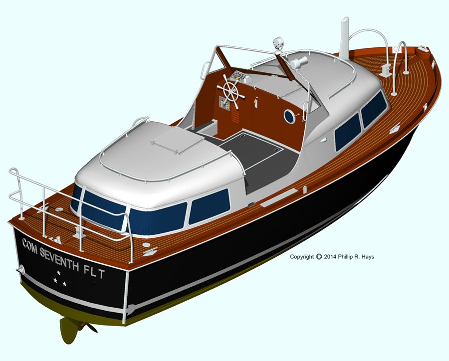
-
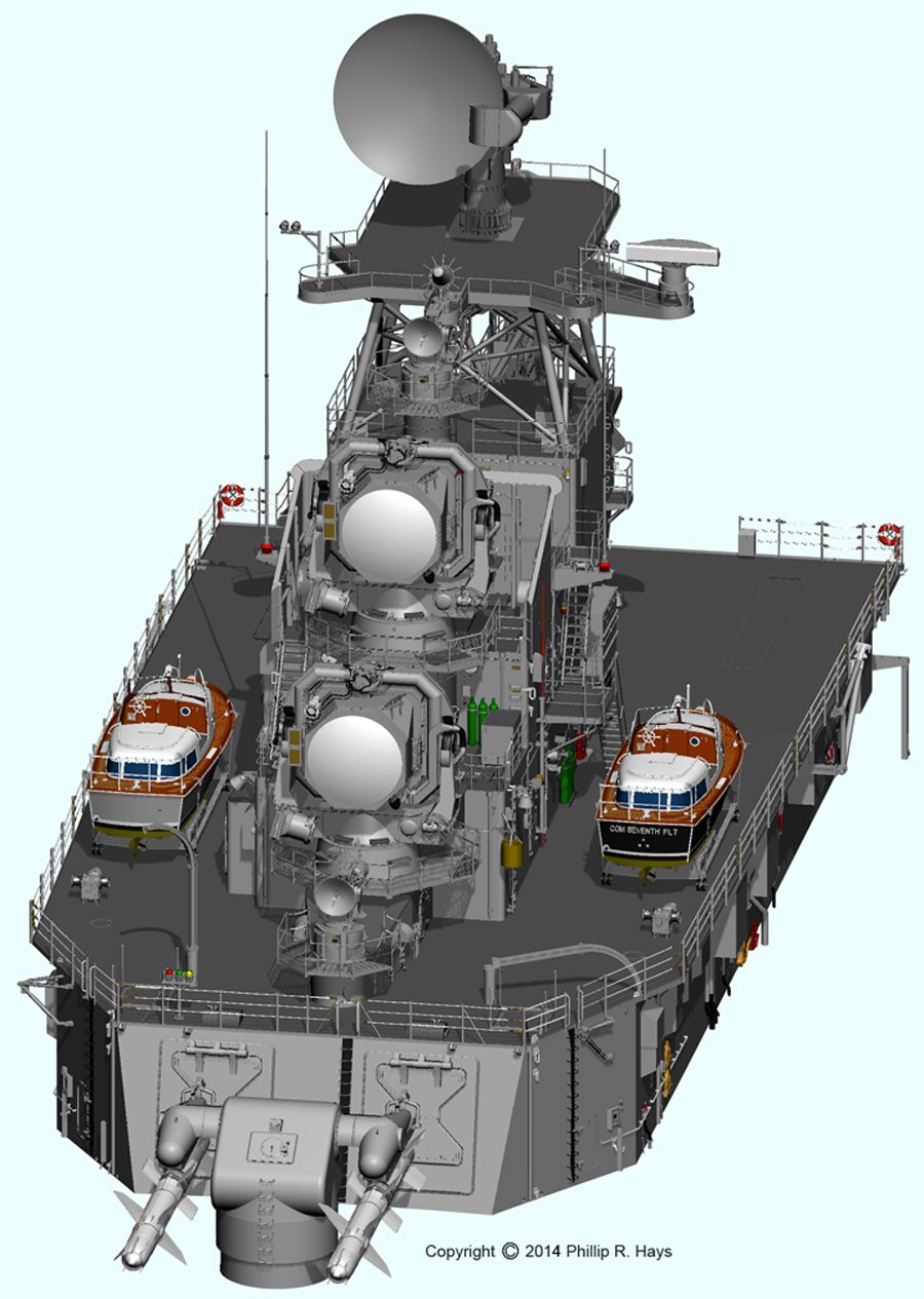
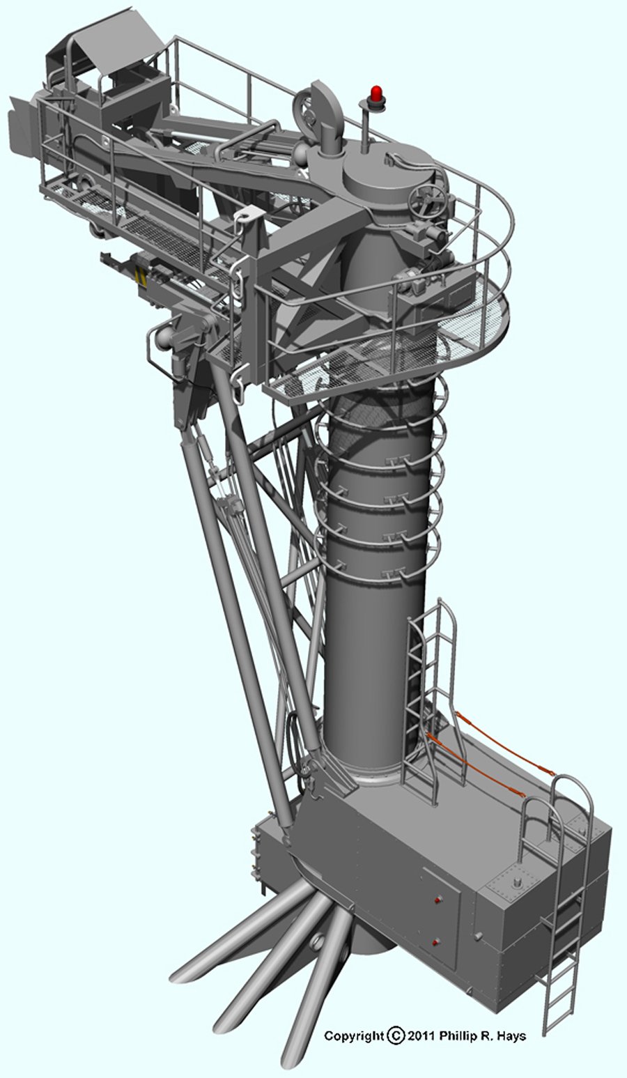
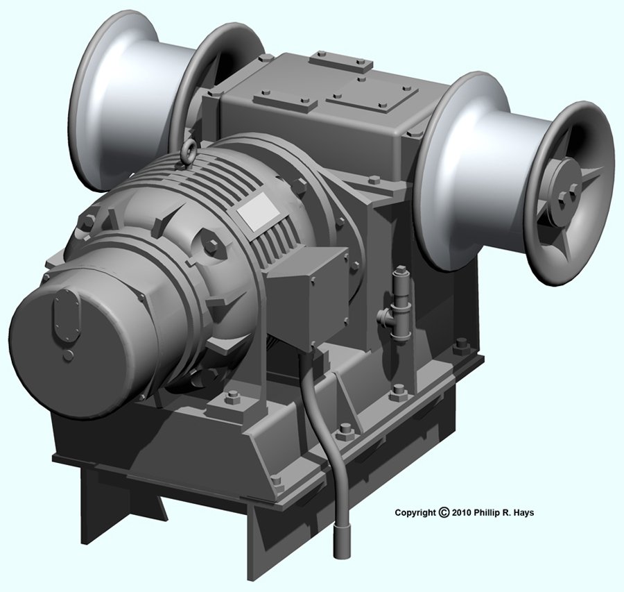
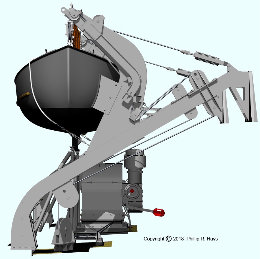
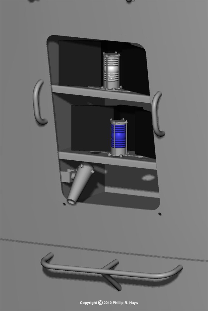
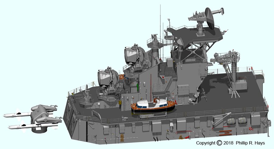
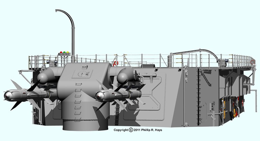
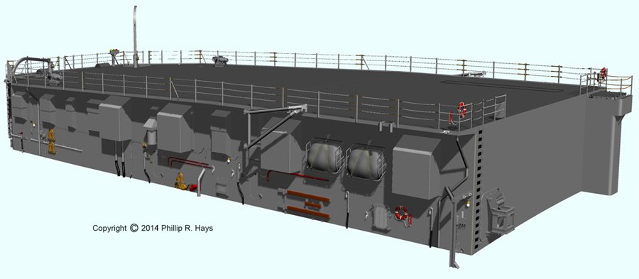
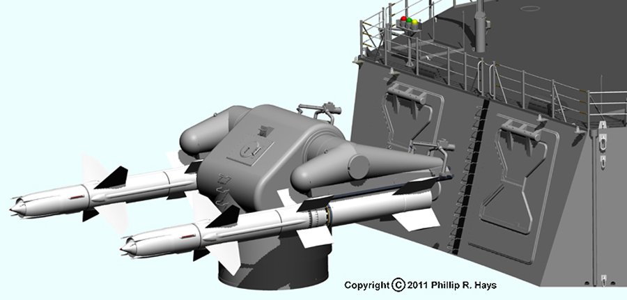
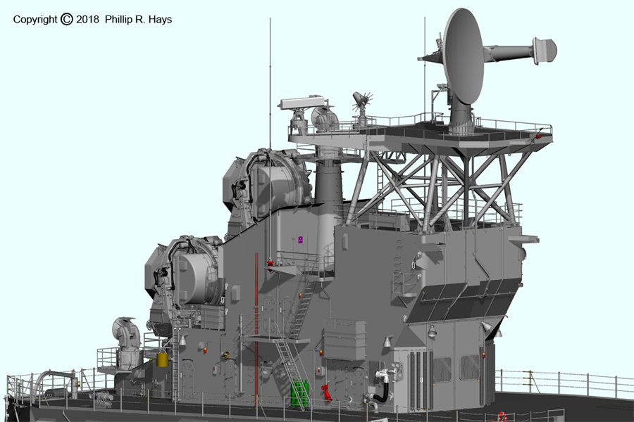
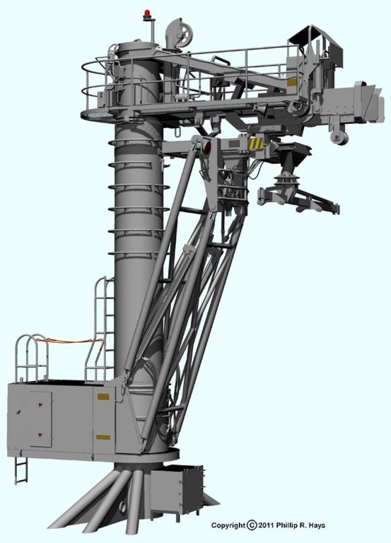
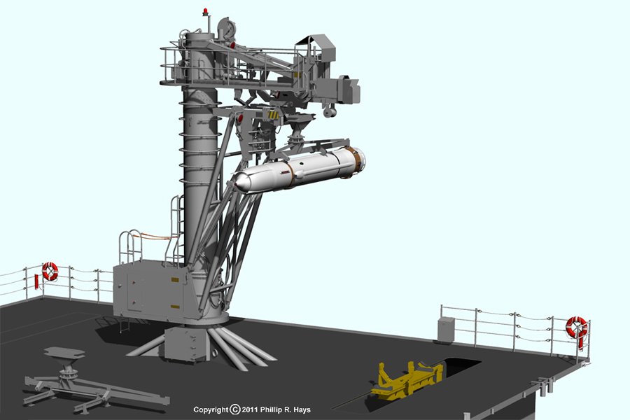
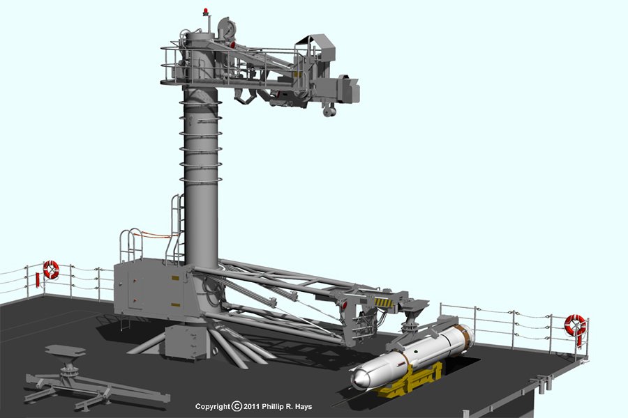
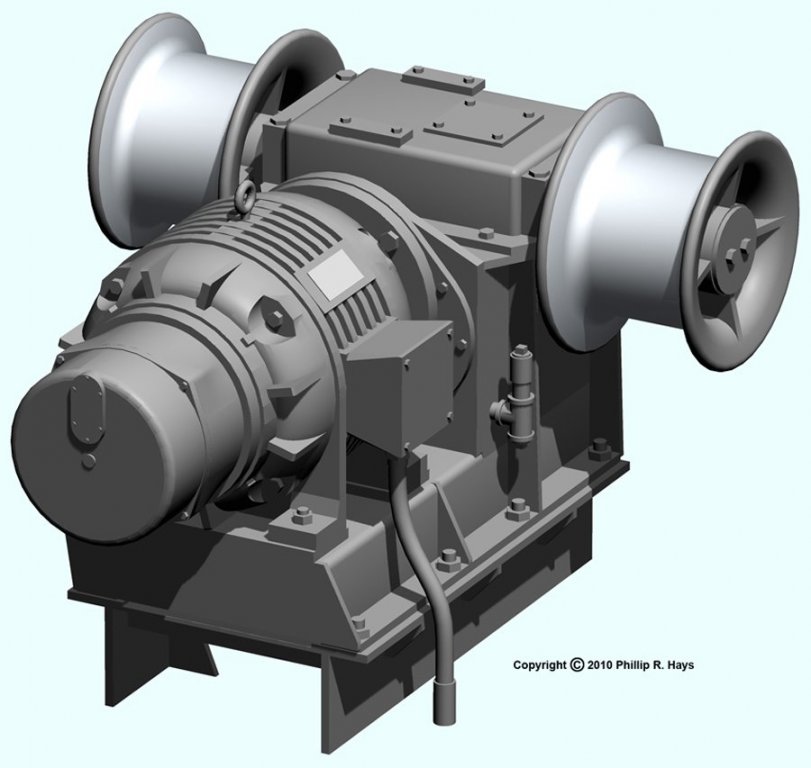
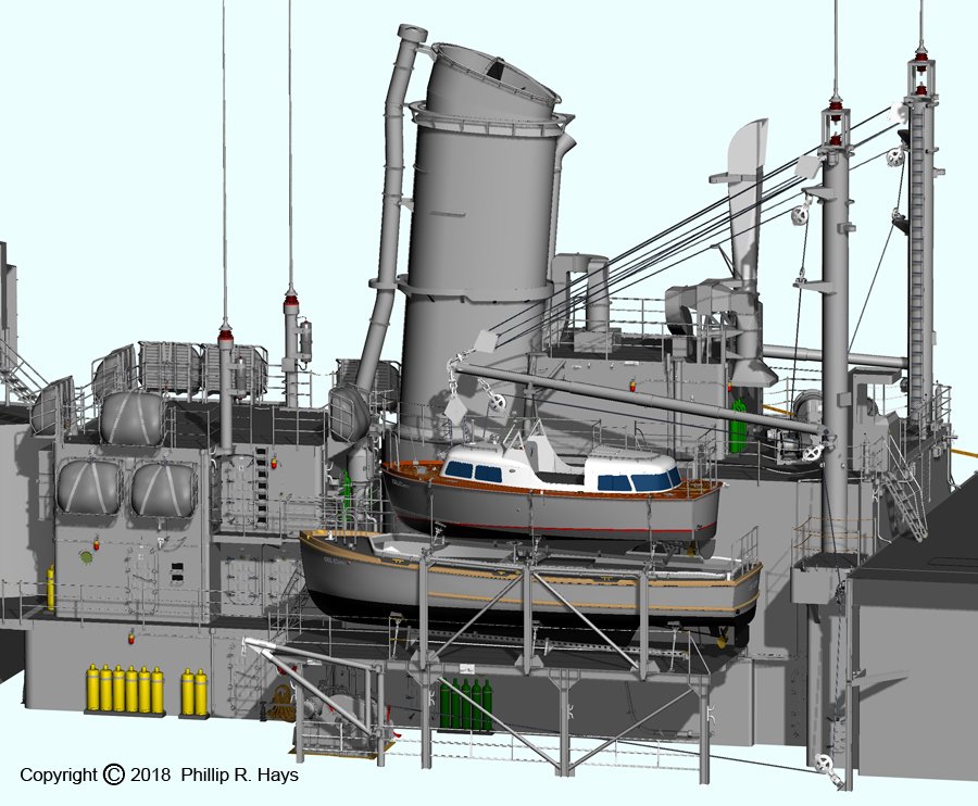
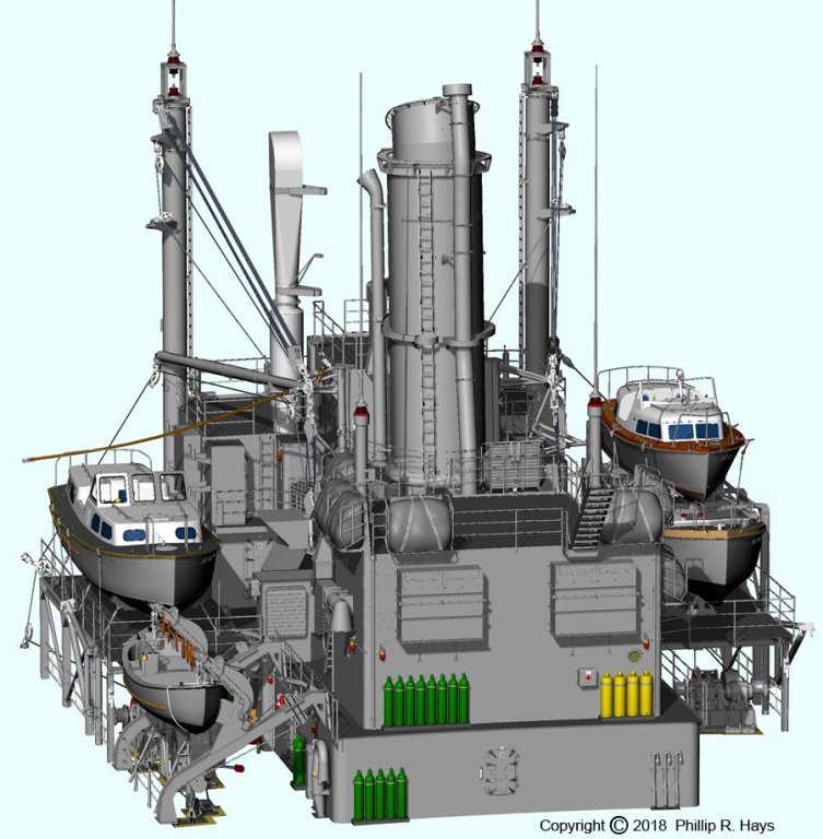
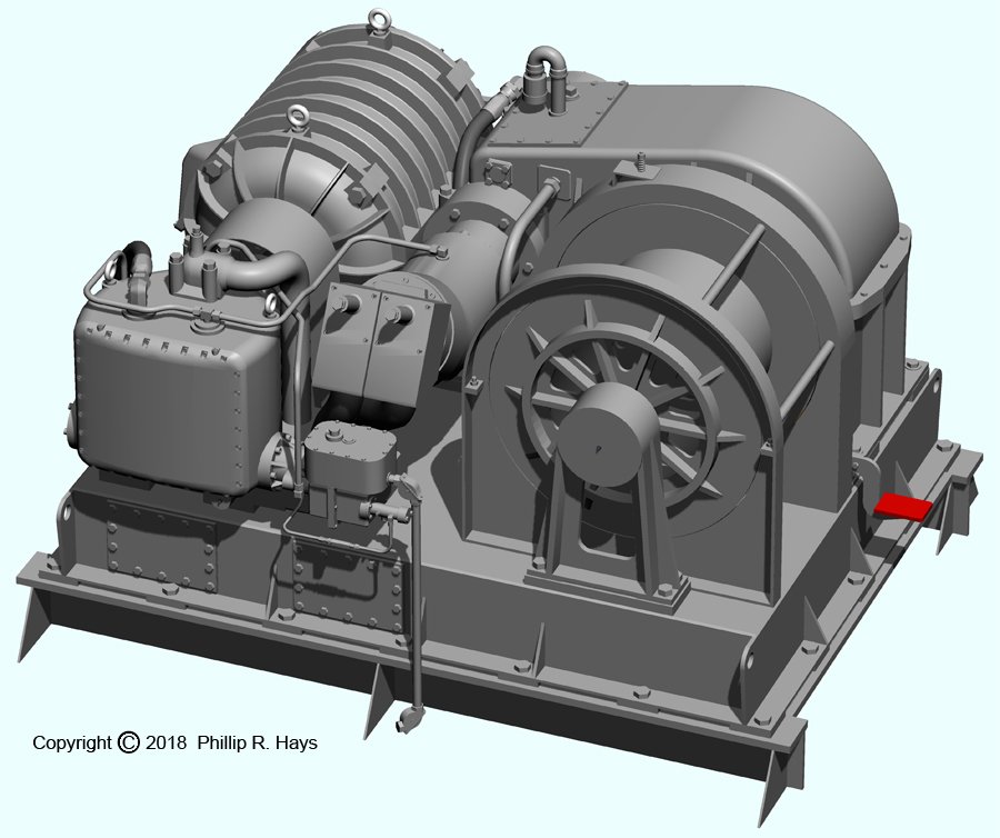
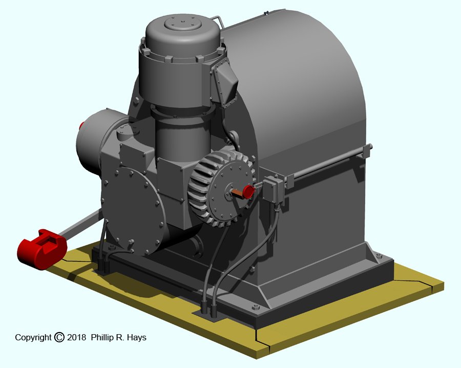
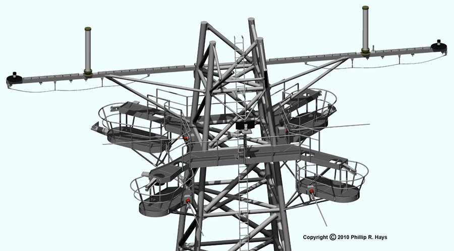
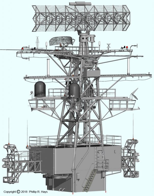
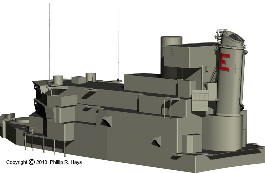
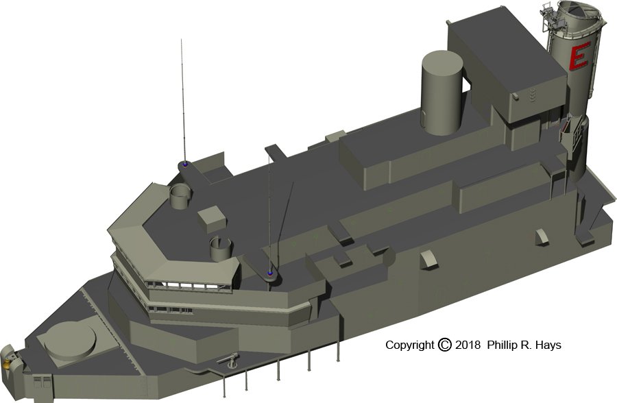
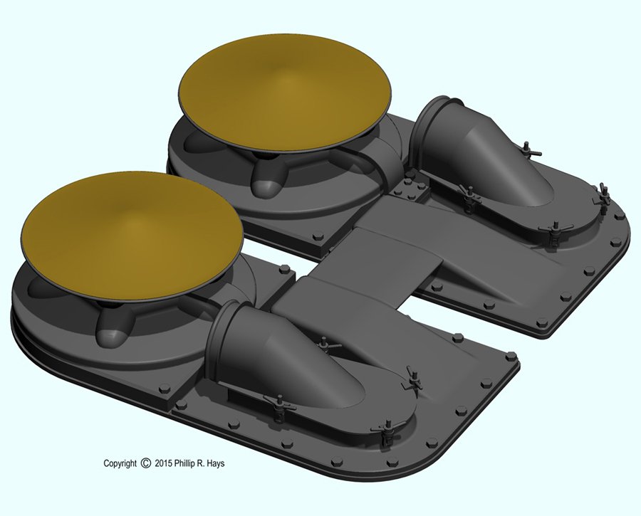
AFTER SUPERSTRUCTURE AND TOWER For the CLG conversion everything above the main deck aft of the midships superstructure was removed. The triple 6"/47 turrets #3 and #4, dual 5"/38 gun mounts #54, #55 and #56, the aft Mk 34 and Mk 37 directors and the deck houses around them, and the aircraft catapults and crane were scrapped. In their place a huge armored missile house was built on the main deck and a new after superstructure and tower were built on top of the missile house. The entire after deck house was part of the Talos guided missile launching and guidance system. The missile house contained the Mk 7 Guided Missile Launching System where the missiles were stored and serviced. The house was made of 1 1/2" Special Treated Steel (armor plate). Including 46 Talos missiles and boosters the house added 400,000 pounds on the main deck. This didn't help stability problems! Missiles were prepared for launching inside the house and then moved onto the Mk 7 launcher rails, passing through armored blast doors in the end of the house. The upper doors carried spanner rails to mate the launcher rails to the launching system rails inside the house. For more information about the Talos launching system go to this link: https://www.okieboat.com/Talos launching system.html The deck house on top of the missile house contained Weapons Control, where the Talos system was operated, and radar rooms for the SPS-30 3D height finder radar, the two massive AN/SPG-49 missile tracking radars and the two AN/SPW-2 guidance transmitter antennas. Talos was a long range (130 nmi.) Mach 2.7 missile designed to intercept aircraft and missiles at altitudes from 50 feet to 75,000 feet. It had an anti-surface ship capability, and an anti-radiation (radar) ARM capability. For these missions it carried a conventional expanding rod warhead. It also had a 2 KT nuclear warhead that could be used against air, surface and shore targets. For more information aout the Talos missile see: https://www.okieboat.com/Talos missile.html Talos was the first anti-aircraft missile system designed by the US Navy, beginning in 1945 before the end of WWII. The program actually spun off the shorter range Terrier missile which was the first to enter service. Talos was a massive system that was installed on only a few cruisers. It was replaced by the newer AEGIS missile system. You can see the stowage locations for the two 7th Fleet 28 foot personnel boats and their cradles. There were two of these little snaking winches, port and starboard, that were used to haul the 28 foot personnel boats and carriages around the top of the missile house. It was the smallest of the ship's winches, with just an electric motor and gear system and no hydraulics. I modeled it from photos and dimensioned sketches made on the USS Little Rock CG-4 museum ship. It was also used to transfer missile warheads into the missile house through hatches in the deck at the rear of the missile house. The after radar tower was much simpler than the other two towers. It was positioned above the radar room for the AN/SPS-30 3D height finder and air search radar. In addition to the SPS-30 antenna an AS-791/UPA-43 Identification Friend or Foe (IFF) interrogator antenna (below left) was mounted on a platform wing. It was slaved to the SPS-30 to allow IFF interrogation of targets. An AS-979A/UKR telemetry antenna (below right) was mounted on a platform extension at the rear of the tower platform. I think (but I am not certain) that this was the antenna used to receive telemetry information from Talos missiles in flight. The missiles sent back airspeed, altitude, fuel consumption, wing motion and radar proximity fuze information to allow analysis of the flight. On the ship's centerline on top of the forward end of the missile house was a large contraption called the Fleet Active Shuttle Transfer (FAST) crane (below). It was designed to operate with similar equipment on replenishment ships to transfer Talos missiles to the OK City's missile magazine. It was capable of transferring a missile or booster every 90 seconds. The operator worked in a small booth at the aft end of the midships superstructure on the O3 level. Missiles would arrive on a shuttle that rode a highline strung between the FAST crane and the FAST system on the replenishing ship. The missiles and boosters were attached to strongbacks carried by the shuttle. The FAST crane would capture the shuttle and strongback, A pantograph arm on the FAST crane lowered the strongback and missile/booster into position above a strikedown elevator (yellow in the images above). The elevator captured the missile and the strongback was released. Then the missile was lowered into the magazine at the forward end of the missile house. The pantograph arm raised and sent the strongback and shuttle back for another load. That's the way it was supposed to work. In reality the FAST crane was a piece of junk. It was exposed to the worst of weather conditions and the complex hydraulic and electrical system failed during transfers more often than not. The real problem was not with the machinery - the Navy did not have enough trained personnel to maintain it. Many complex systems were introduced into the navy in the 1950s and 1960s - nuclear submarines, nuclear powered ships, nuclear weapons, sub launched ballistic missiles, surface to air missiles, jet aircraft with complex avionics systems, air to air and air to surface missiles, and many new types of radars. There were not enough intelligent people joining the Navy and not enough training facilities to train them. First priority went to nuclear submarines and the air wings. There was a chronic shortage of trained personnel on all other units. We just didn't have enough trained men on the OK City to maintain the missiles, launching system, radars, guns and other systems to spare anyone to baby sit the FAST system. The FAST crane was removed in late 1971 and only the kingpost at the center remained. We used the FAST kingpost and burtoning winch for underway replenishment of missiles and powder for the guns. The FAST crane is the reason I decided to model the ship as it was in the summer of 1971, just before the FAST crane was removed. I wanted to model it. Phil


- 48 replies
-
- 5
-
-
- 3d cad
- cleveland class
- (and 1 more)
-
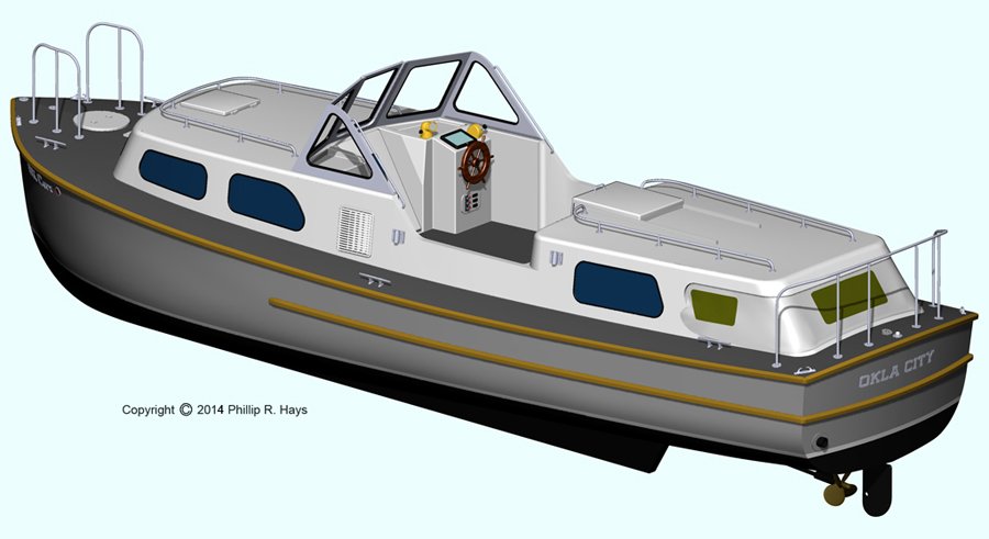
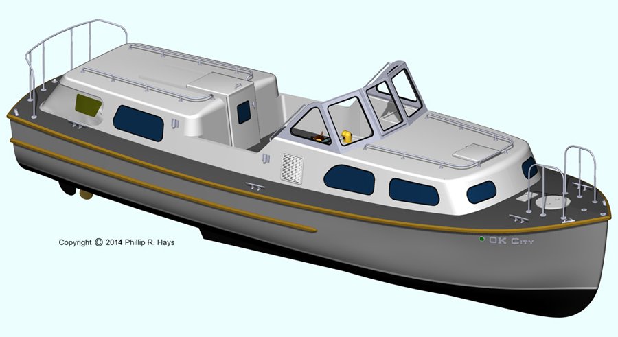
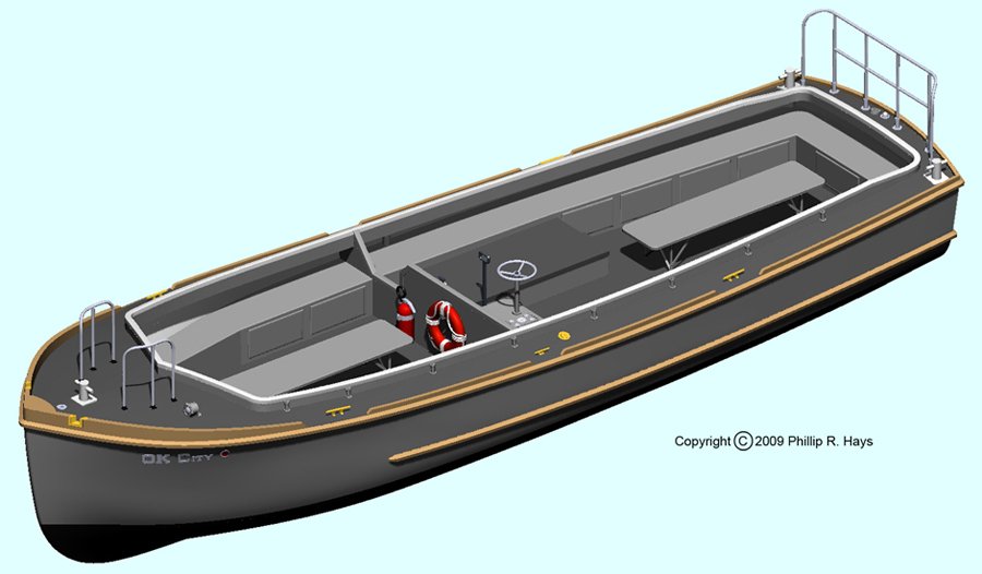
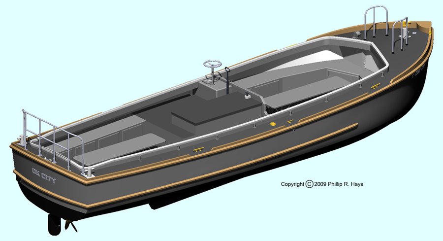
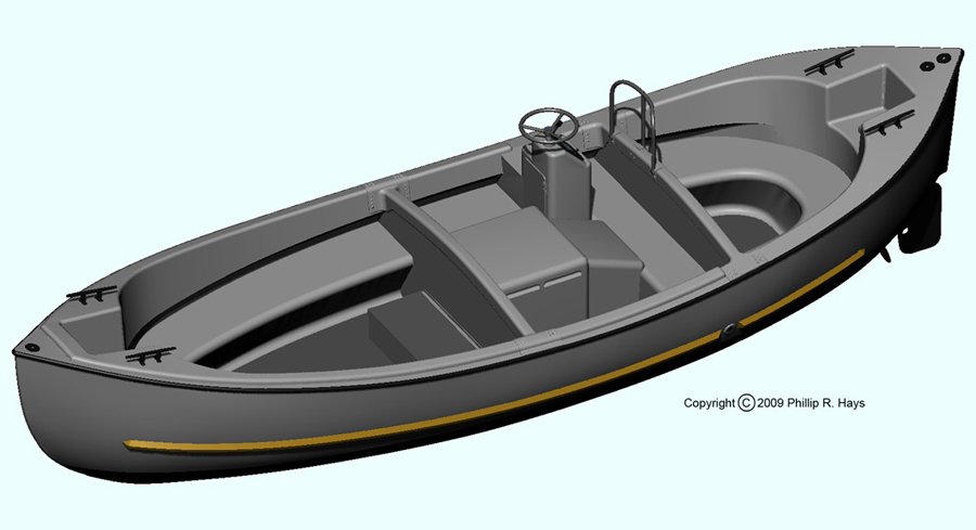
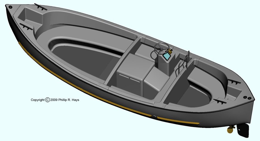
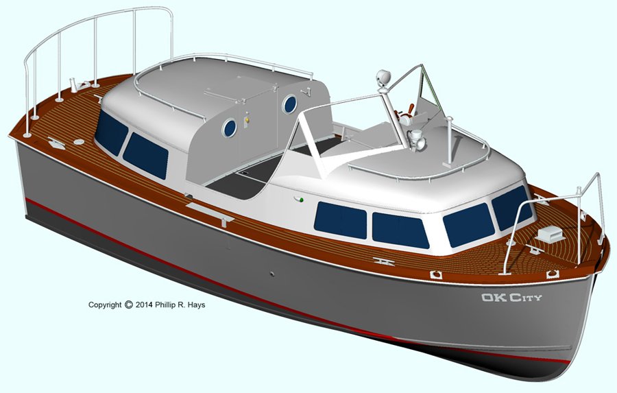
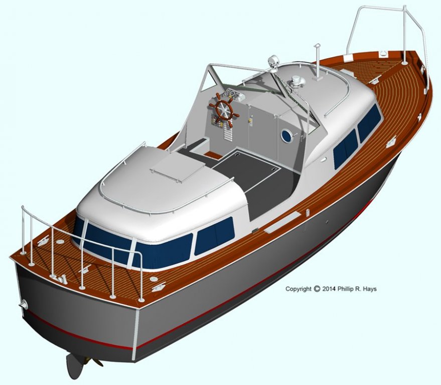
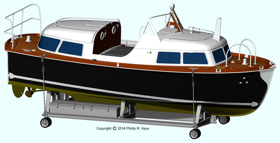
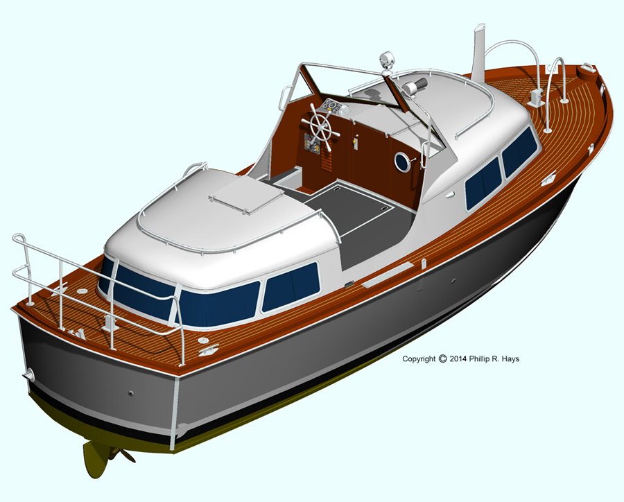
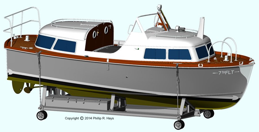
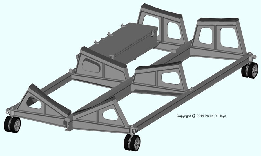
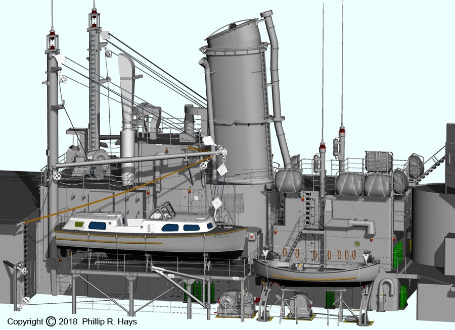
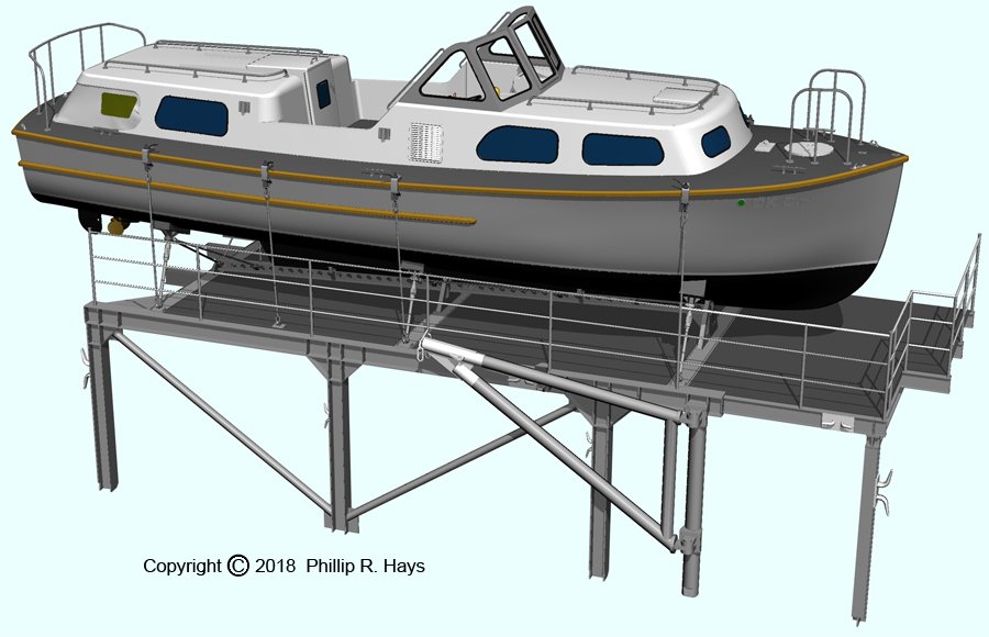
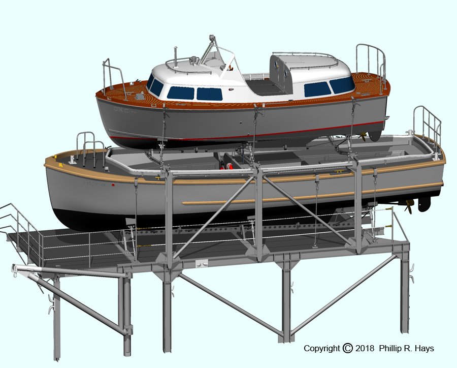
SMALL BOATS The ship had a good collection of small boats even after the weight reduction measures that eliminated two of the 40 foot utility boats. In addition to the ship's complement of four boats, when the ship served as 7th Fleet flagship it carried two additional boats on portable cradles atop the missile house (described later). Plans for most of the Navy's small boats and auxiliaries that were used in the mid 20th century are available from the Barbour Boat Works Inc. records (#758) at the J. Y. Joyner Library at East Carolina University, Greenville, North Carolina, USA. https://digital.lib.ecu.edu/11208 40 Foot Personnel Boat Mk 4 This boat was used to ferry personnel from ship to shore or to other ships. 40 Foot Utility Boat Mk 2 The utility boat was used for many things. We used it to carry the crew to shore for liberty and to bring back personal belongings that were purchased in places like Hong Kong. The center benches folded to make room for large cargo. 26 Foot Motor Whaleboat Mk 10 The whaleboat was used to carry personnel and mail between ships and to shore. It was also launched during man overboard drills - and the real thing - to fish people out of the ocean. 28 Foot Personnel Boat Mk 6 Captain's Gig This boat was assigned to the USS Oklahoma City, and served as the Captain's gig. 28 Foot Personnel Boat Mk 6 Admiral's Barge While the 7th Fleet staff was aboard the ship carried the Admiral's Barge on a portable boat cradle . It was stowed on top of the missile house aft. It was tricked out with more details and chrome than the other boats. 28 Foot Personnel Boat Mk 6 7th Fleet Staff Boat The 7th Fleet Staff Boat was used by the Chief of Staff and other 7th Fleet officers - there were lots of them! It was tricked out better than the Captain's Gig, but not quite as nice as the Admiral's Barge. It was also stowed on a portable boat cradle aft on the missile house. The portable boat cradle was another challenge. I have found no plans but I do have several good photos of the cradles used on the OK City. The ship had two snaking winches on the missile house that were used to drag things around. They were used to move the boat and cradle from the stowed position on the after part of the missile house top to the forward part of the missile house top where the boats could be lowered and raised using the boat booms. Phil

- 48 replies
-
- 4
-
-
- 3d cad
- cleveland class
- (and 1 more)
-
Best Software for Deck Plank Design?
Dr PR replied to knightyo's topic in CAD and 3D Modelling/Drafting Plans with Software
If all you need is dimensioned 2D plans there are several free or cheap CAD programs that will do that. With any program it is very important to have a user's forum where you can ask experienced users how to do something. It is also important that the forum be open to all without charge. I can recommend the 2D version of the program I use, DesignCAD. It has a very active user forum with members from all around the globe. The tech support people and programmers monitor the forum and chime in to answer questions experienced users haven't answered. I should add that I have been using the program since 1988 and I am a volunteer beta tester for the program, so I am a bit biased. I do not have any other connection with the company, and I am not a stock holder - just a user. Have a look at the forum: http://forum.designcadcommunity.com/ You do not have to be a member to ask questions. Go ahead an ask the forum members what program they would recommend for 2D drafting. You might be surprised to hear other programs recommended! Be patient - the forum has been a bit slow for the last few days. This is not normal. Here is a link to the program's web site: https://www.turbocad.com/designcad/designcad-2018.html It costs $50.00 US. Phil -
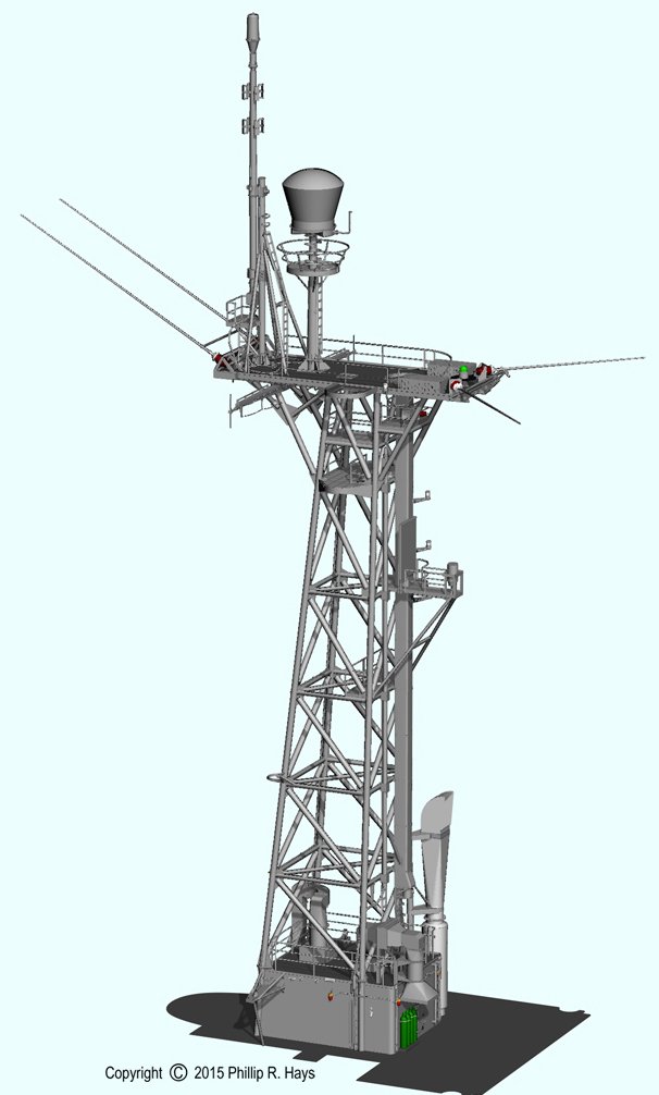
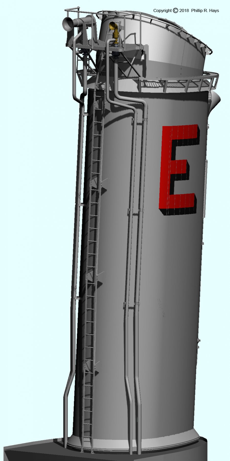
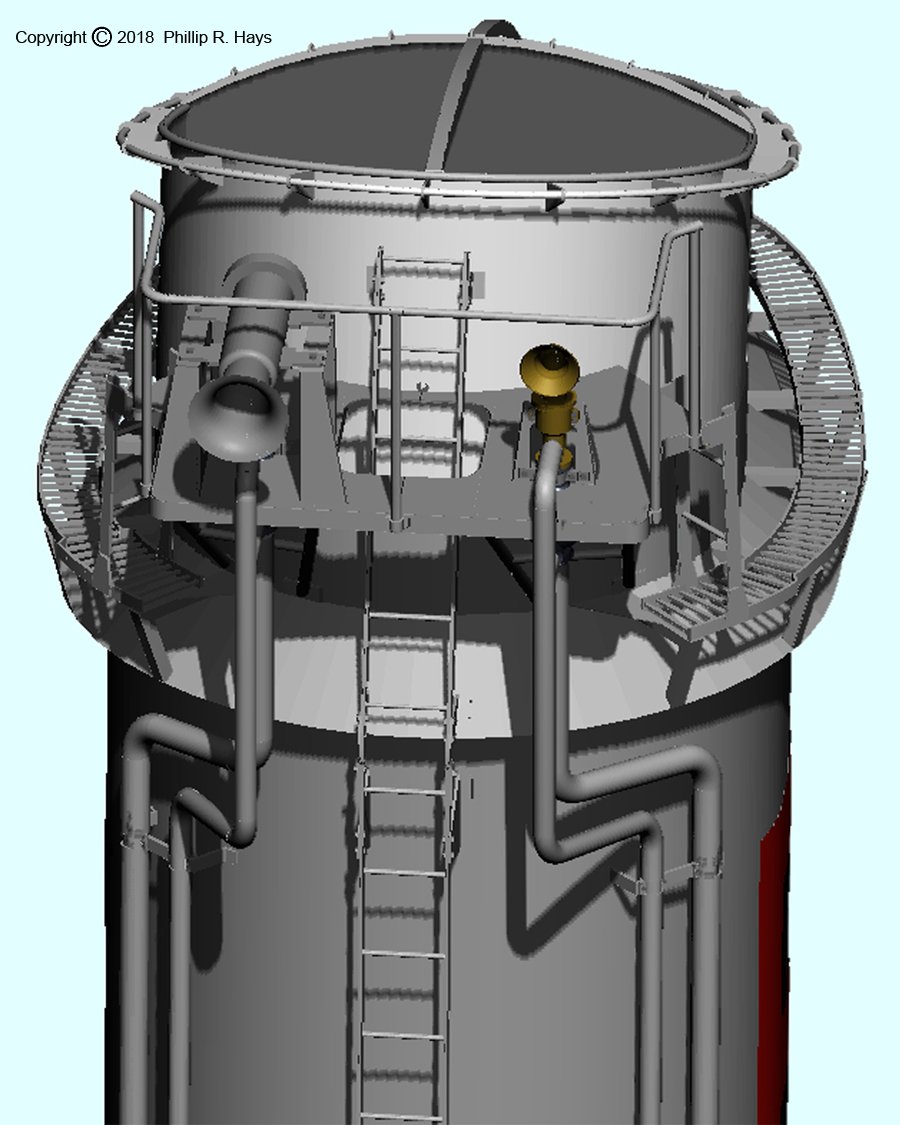
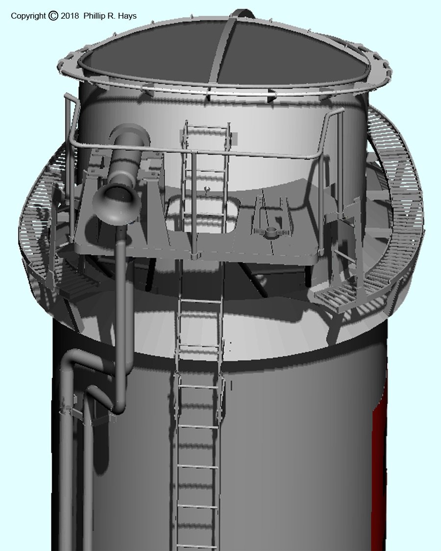
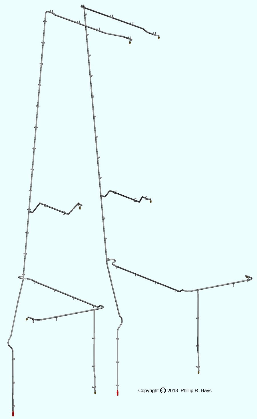
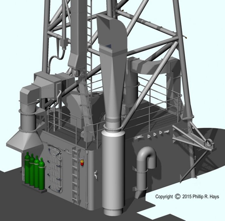
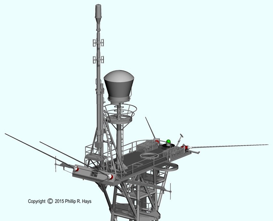
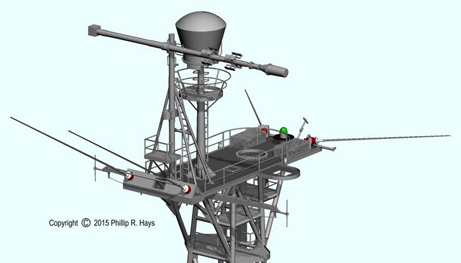
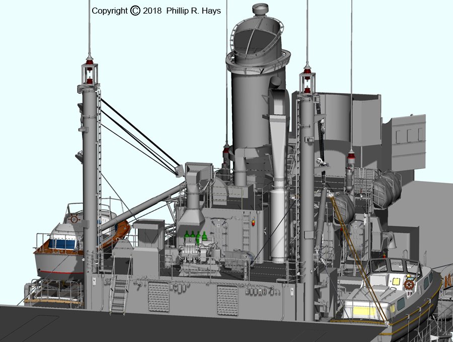
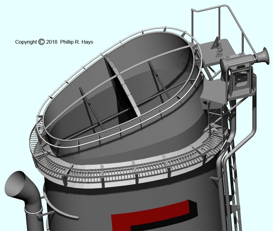
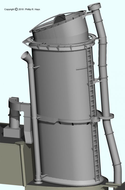
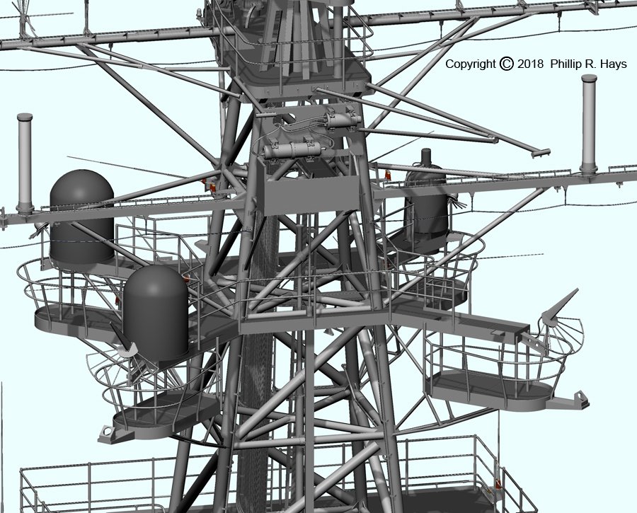
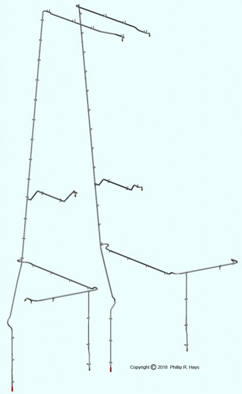
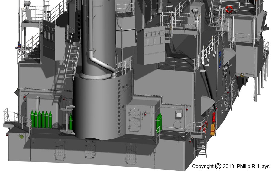
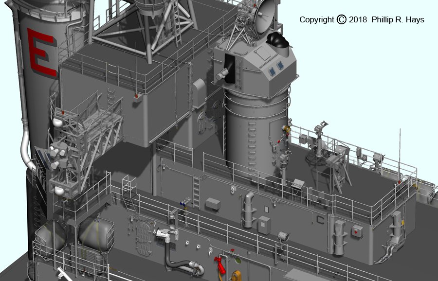
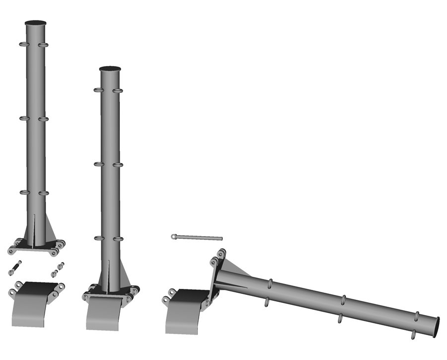
MIDSHIPS RADAR TOWER This tower originally carried a radar antenna, but it was removed to reduce topside weight. The basic structure was similar to the forward radar tower. The tower rested upon the top of the O3 level radar room. Well, it was a radar room while the 3D radar antenna was on the tower, but after the antenna and associated radar equipment were removed the compartment became an office with very good heating and air conditioning. The large vent stack on the starboard side of the compartment was Charlie Noble. The arms extending from the deck house sides were the rests for the stowed boat booms. The platform at the top of the tower carried four 35 foot whip antennas and a few other smaller antennas. A short stub mast carried the ship's Tactical Air Navigation (TACAN) antenna in the dome. It was used by helicopters to determine the range and bearing to the ship. It was also used by other ships to facilitate rendezvous. Another mast at the forward edge of the platform carried a few more antennas and the ship's AN/URD-4 radio direction finder at the top that was used for search and rescue operations. This mast was hinged about half way up so it could be folded sideways. There were a few bridges the ship might have to pass under that were lower than the raised mast. Phil

- 48 replies
-
- 6
-
-
- 3d cad
- cleveland class
- (and 1 more)
-
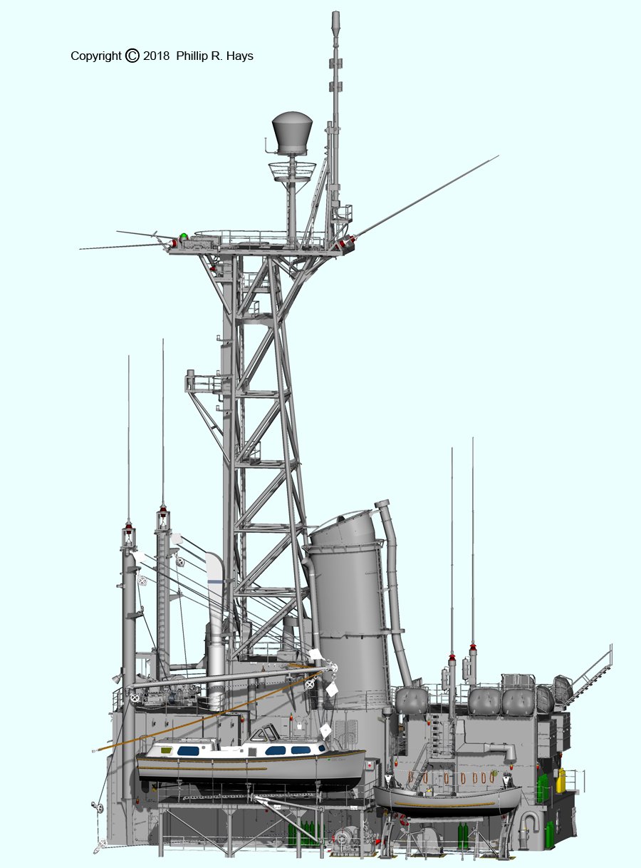
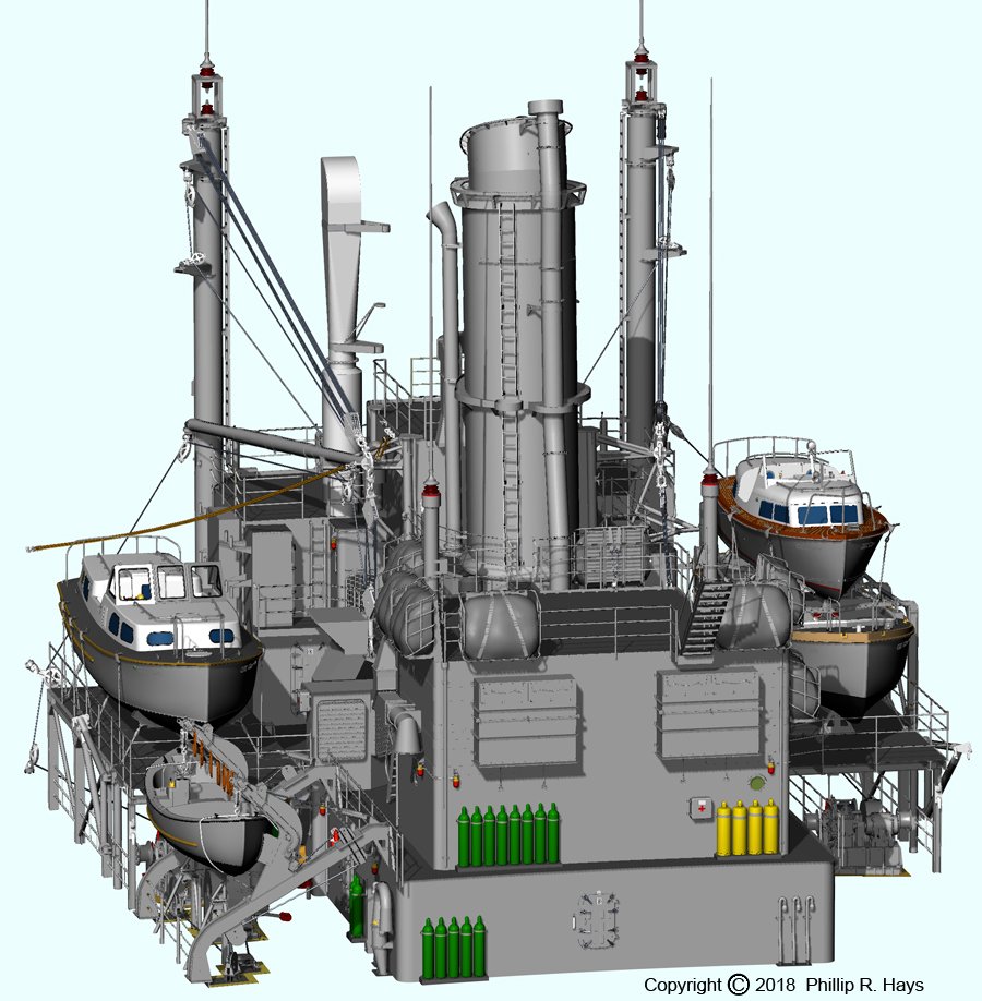
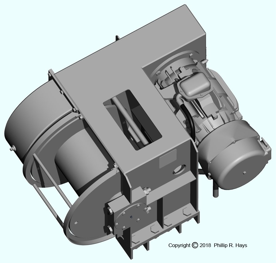
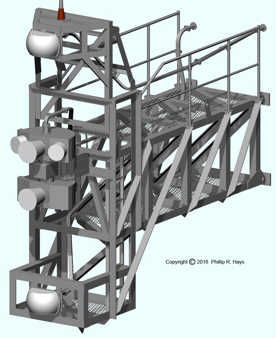
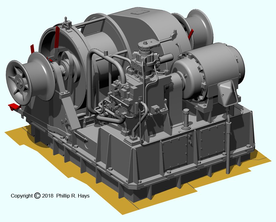
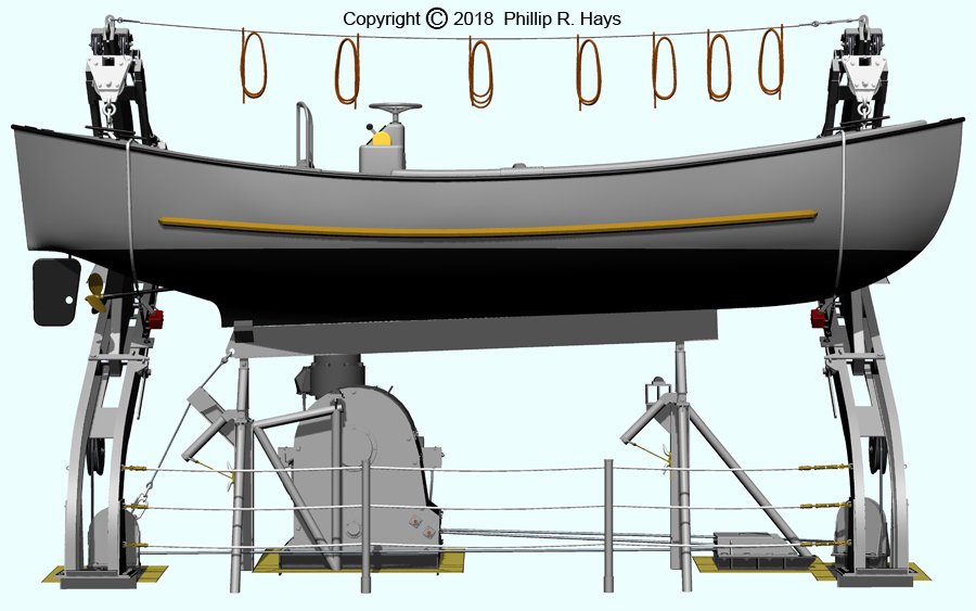
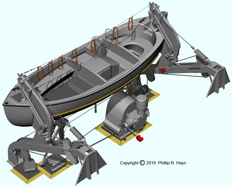
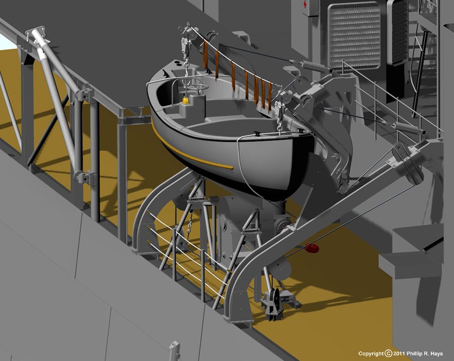
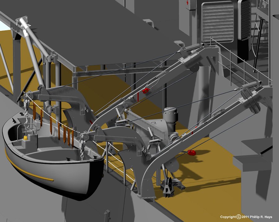
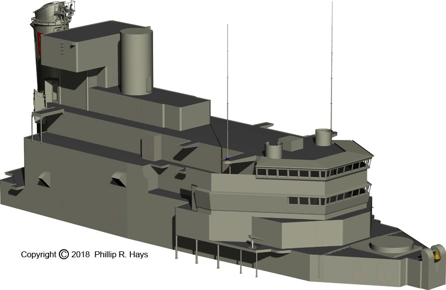
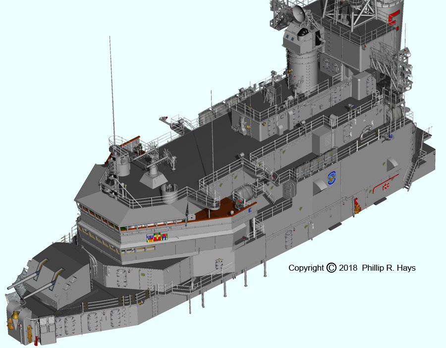
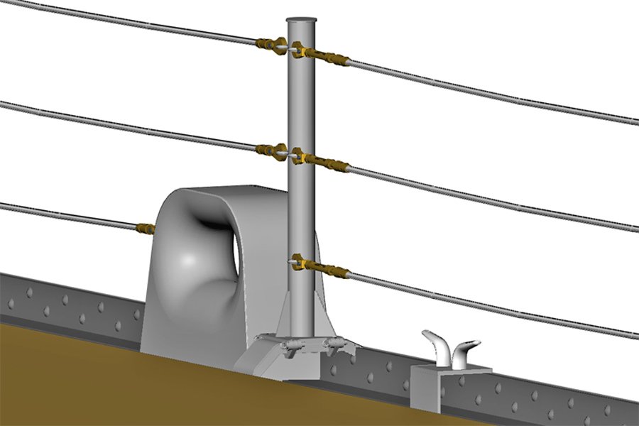
MIDSHIPS SUPERSTRUCTURE Like the forward superstructure, almost everything from CL-91 was removed amidships, leaving the aft smoke pipe and its supporting structure. Then a new superstructure was built around it to support the new midships radar tower. The blueprints for the original CLG conversion included a 3D radar on top of the tower and more antennas on a platform just below the top. It had large double level boat davits port and starboard midships that each housed a 28 foot personnel boat on the bottom level, and a 26 foot motor whale boat above that. It also included double nested boats on the boat decks, with two 40 foot utility boats on the port side and a 40 foot personnel boat nested over a 40 foot utility boat on the starboard boat deck. The ship was very top heavy and rolled badly in even moderate seas. After a year or so in service the ship went back into the yards for a 15 month overhaul to reduce topside weight. The 3D radar was removed and replaced by the SPS-30 3D radar on the after tower. Most of the other antennas at the top were moved to lower places on the forward radar tower. The double level boat davits were removed and replaced with one single level gravity davit on the starboard side that carried one motor whale boat. Two of the 40 foot utility boats were eliminated, and one 28 foot personnel boat (the Captain's gig) was nested over the remaining 40 foot utility boat on the port boat deck. Only the 40 foot personnel boat remained on the starboard boat deck. No other CLG was modified to this extent. The forward part of this superstructure contained living quarters for the CPOs and the trash burner. The aft part was a collection of shops and offices. At the aft end of the deck house were two kingposts port and starboard. Each had a large boat boom that was stowed along side the deck house when not in use. Between the kingposts, to the port of the ship's center line, was a small cabin to control the FAST crane (described later in the after superstructure section). Three winches were located on the O3 level aft of the compartment below the tower. Two topping winches (left above) were used to raise and lower the boat booms. The burtoning winch (right above) was the heavy lifter that was used for highline transfers (described later in the after superstructure description). The image above shows the starboard boat boom with rigging to the topping winch on the O3 level. Below the boat deck with the 40 foot personnel boat was the starboard boat winch on the main deck. Another boat winch was below the port boat deck. Cable from these winches was rigged to blocks at the end of the boat booms. Boom vangs (lines to swing the boom out and back) were rigged to the sides of the superstructure and to positions aft on the missile house. The boat winches raised and lowered the boats, but the booms could also be used to lift objects like vehicles, boats or supplies onto the top of the missile house. For in port missile transfers the boat booms lifted missiles and boosters from the pier or from barges and lowered them onto the missile house strike down elevators (described in the after superstructure section). The boat winch (left above) and motor whaleboat winch (above right) were modelling projects in themselves, as were the other two winches. I found patent drawings for the whaleboat winch, but the other three winches were drawn from photos and dimensioned sketches I made on the USS Little Rock CG-4 museum ship. If I believed in conspiracy theories I would swear that the complex mass of piping on the valve block of the boat winch was designed by a diabolical engineer who knew that someday some ship modeller would try to replicate it! The whaleboat davits were a mystery. They were single bank, double arm trackway gravity davits. They weren't on the original Clevelands or on the CLG conversions so they aren't in the blueprints. The Little Rock still has the original CLG two level davits, so my visit there was no help. I looked in all sorts of Navy training manuals and on line sources, and found no pictures or descriptions of these davits. Fortunately I had several good high resolution photos I made of the stowed whaleboat, so I could use photoguesstimation to figure out the dimensions. The davits allowed the boats to be launched without power, using gravity to lower the boat. When stowed, the boat rested upon a strongback that was lowered prior to launching. Launching the motor whaleboat proceeded in several steps. First the straps that tied the boat to the davits were removed to allow the boat to swing free. Next the strongback below the boat was lowered. Then the davit arms were released to slide down the trackways and into position over the side. Then the crew got in and grabbed the rope loops hanging above the boat - just in case something went wrong and they needed to get back aboard. Then the boat was lowered into the water, using the brake on the whaleboat winch to control descent. Recovering the boat was just the reverse procedure, but using the whaleboat winch to haul the boat and davits back into the stowage position. The starboard boat deck (left above) was almost the same as shown on the blueprints, with minor changes. The 40 foot personnel boat rested in a cradle and was tied down when stowed. The port boat deck (right above) was modified significantly when the upper 40 foot boat was replaced by the 28 foot personnel boat. The 40 foot boat rested in a cradle similar to the one on the starboard side. The cradle for the 28 foot boat was hinged to the superstructure on the inboard side. After the 28 foot boat was removed the cradle could be swung up and latched to clear the way for lifting the 40 foot boat. Phil


- 48 replies
-
- 5
-
-
- 3d cad
- cleveland class
- (and 1 more)
-
Does anybody have any experience of this?
Dr PR replied to Moxis's topic in CAD and 3D Modelling/Drafting Plans with Software
The web site has a lot of hype and absolutely no specifications. What is the resolution of the 3D printer? What is the minimum step size for the linear positioners? What is the maximum X, Y and Z motion? They say a 500 mW laser is available - from where? What does it cost? They say it will do CNC milling, but don't mention the motor, specs, what kind of tools it takes, etc. Looks like a scam to me. Phil -
Best Software for Deck Plank Design?
Dr PR replied to knightyo's topic in CAD and 3D Modelling/Drafting Plans with Software
Alan, I would say there is no "best" program. All drawing and CAD programs are different, using different methods to achieve the same end results. There are two general types of programs you can use. One type is a CAD drafting program, and the other is an illustration program. They are intended for different purposes. Whatever program you decide to use, it will take you quite a bit of time to learn how to use it. And it can be a real distraction from working on your model. CAD programs are used to create detailed dimensioned drawings used for product development and production, driving NC milling machines and lathes, 3D printing and such. They can be used to print 2D construction drawings and blueprints. CAD programs can create 2D and 3D models. They had a great variety of commands for precision drawing. Because they have so many drawing functions it can take a long time to learn to use them. Examples are SolidWorks, AutoCAD and the program I use, DesignCAD 3D MAX. The other type is Illustration programs. These are intended to make pretty pictures, and usually have far superior rendering capabilities to the CAD programs. However, they may not have functions for precision drawing or provisions for creating 2D dimensioned plans, and if they do they are fairly primitive compared to CAD programs. Rhino, Blender and Sketchup are examples. **** What do you want to do? Is your goal to print out 2D deck plans? If so you should be sure that the program you use has these capabilities: 1. Does the program have a 2D drawing mode? This is necessary for 2D plans that you print on paper. 2. Does the program have provisions for drawing in exact scale? Some sketching and illustration programs draw in arbitrary "drawing units" so everything is scaled relative to everything else, but with no actual real world dimensions. 3. Does the program have the ability to print 2D diagrams to scale. Some 3D illustration programs can print images, but only of the 3D models, and only as views with perspective, lighting, shadows, etc.. These are not usable for 2D plans. Phil -
I suspect it has had some effect on my brain, too! Phil
- 48 replies
-
- 2
-
-
- 3d cad
- cleveland class
- (and 1 more)
-
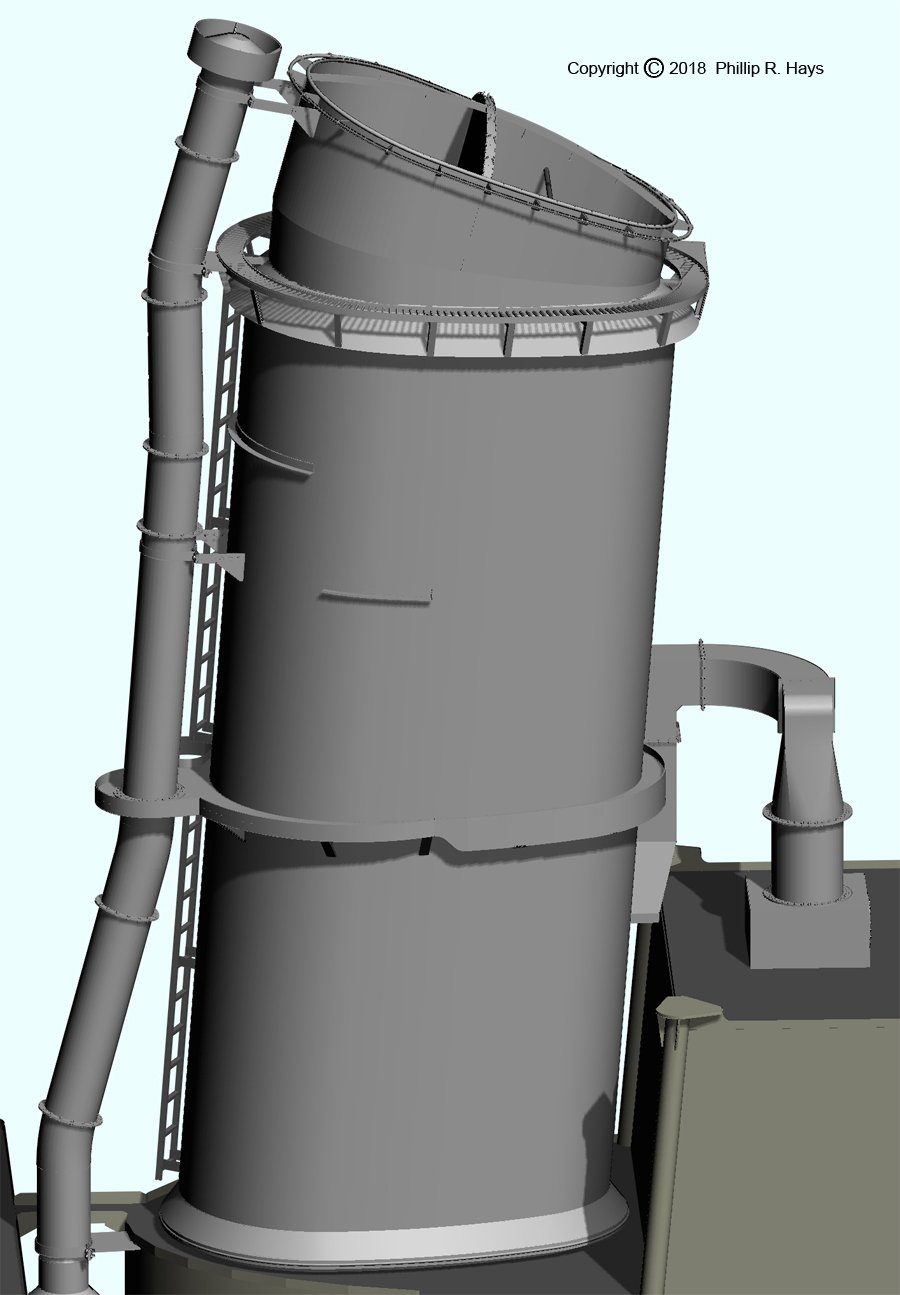
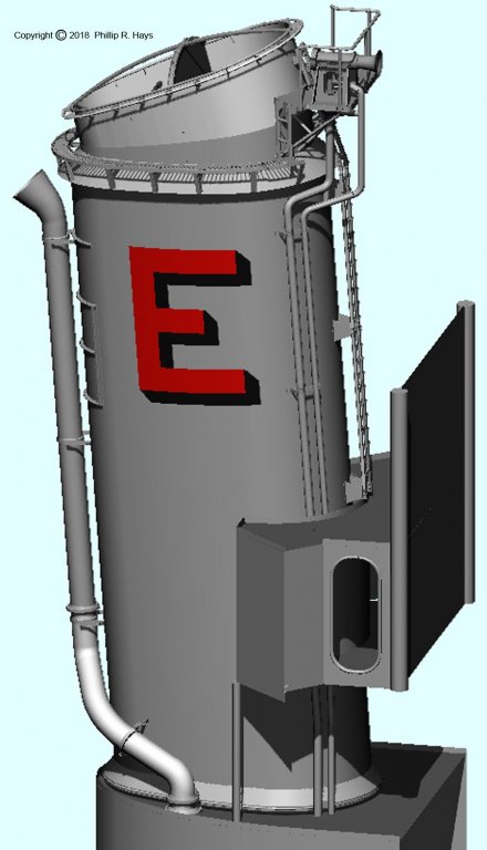
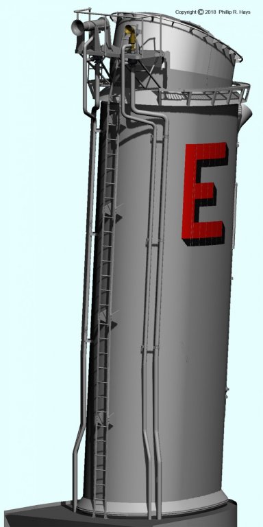
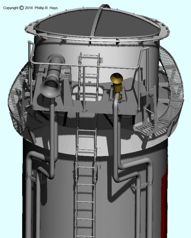
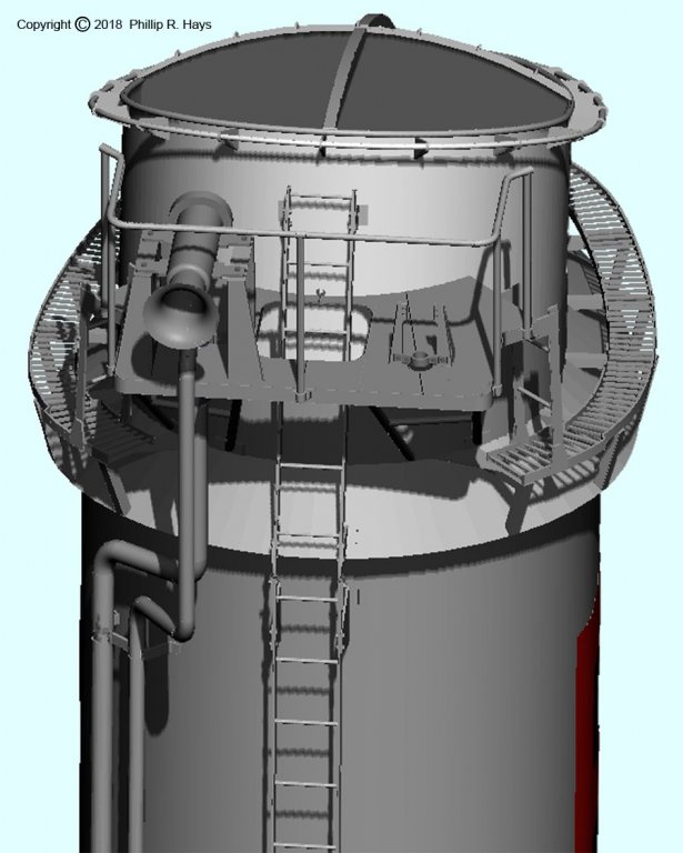
SMOKE PIPES The smoke pipes (funnels) should have been easy. The Cleveland blueprint set included many pages of drawings. Unfortunately, some parts were illegible due to poor exposure when creating the microfilm. Fortunately, I found duplicates of these drawings in the microfilm sets for later versions of the ships, built in other yards. Forward Smoke Pipe The left image (above) shows the CLG configuration of the forward smoke pipe, with the O4 level weather shelter for the signals crew. The right image shows the original WWII Cleveland configuration. The WWII ships had both a steam whistle and a steam siren on the platform on the forward smoke pipe, with the associated piping running up the sides of the structure. Hot steam flowed up one pipe and colder steam and condensed water drained back down the other. The blueprints show the whistle and siren in detail. The large boiler pressure relief pipe in the left CLG picture was the same on the original Cleveland ships. The WWII configuration had a searchlight platform port and starboard at the rear edge of the forward smoke pipe at the O4 level. The image on the left above shows the CLG configuration with only the whistle. The right image shows the WWII configuration with the whistle on the left, the siren on the right, and associated piping. Early Clevelands had the hand rails around the top of the funnel running parallel to the catwalk. Later ships from different yards had the handrails as shown around the very top of the opening. When in port we normally had only one boiler (out of four) fired, and the other three cold iron. Each boiler had an uptake to either the forward or aft half of a funnel - a transverse separator plate ran down the length of the funnel to where the uptakes came together. The cold halves of the funnel tops were covered with canvas covers to keep out birds, bugs and the weather, and only the active boiler/uptake flue was left uncovered. The transverse bar running across the top of the funnel had several sets of "lady finger" hooks that the canvas covers fit over, and the outer edges of the covers were laced to the handrails. When another boiler was lighted the cover over that flue had to be removed, and when the former active boiler had cooled the cover was placed over its flue. After Smoke Pipe The aft smoke pipe was basically the same as the forward pipe, but with a few different details The boiler pressure relief pipe was at the starboard rear on all Cleveland ships, including the CLGs. The contraption behind the smoke pipe on the O4 level was a vent exhaust for the radar room. The large pipe running up the forward edge of the funnel was the trash burner smoke pipe. We burned outdated classified documents in the trash burner. The USS Cleveland CL-55 and subsequent ships had the trash burner pipe running up the aft port side of the funnel. Later ships constructed in different yards had the pipe running up the front edge as shown. However, ships built in one yard had the trash burner at a more forward position, with the smoke pipe curving forward over the midships deck house and then running up the aft port side of the forward funnel, along side the boiler relief pipe! This is an easy way to identify Cleveland class ships made in the Newport News Shipyard. Original Clevelands did not have the ladder running up the forward starboard side of the funnel. Instead a ladder came up from the superstructure behind the funnel to the small triangular extension of the catwalk. Although the ladder was added to the forward side of the funnel in the CLG conversions the small catwalk extension was never removed. The original Clevelands had a searchlight platform on forward port and starboard sides of the funnel at the O5 level, and some later ships had a 20mm gun tub on the aft port and starboard sides at the O3 level. The narrow platform at the O5 level is the remnant of the original searchlight platforms. Phil


- 48 replies
-
- 7
-
-
- 3d cad
- cleveland class
- (and 1 more)
-
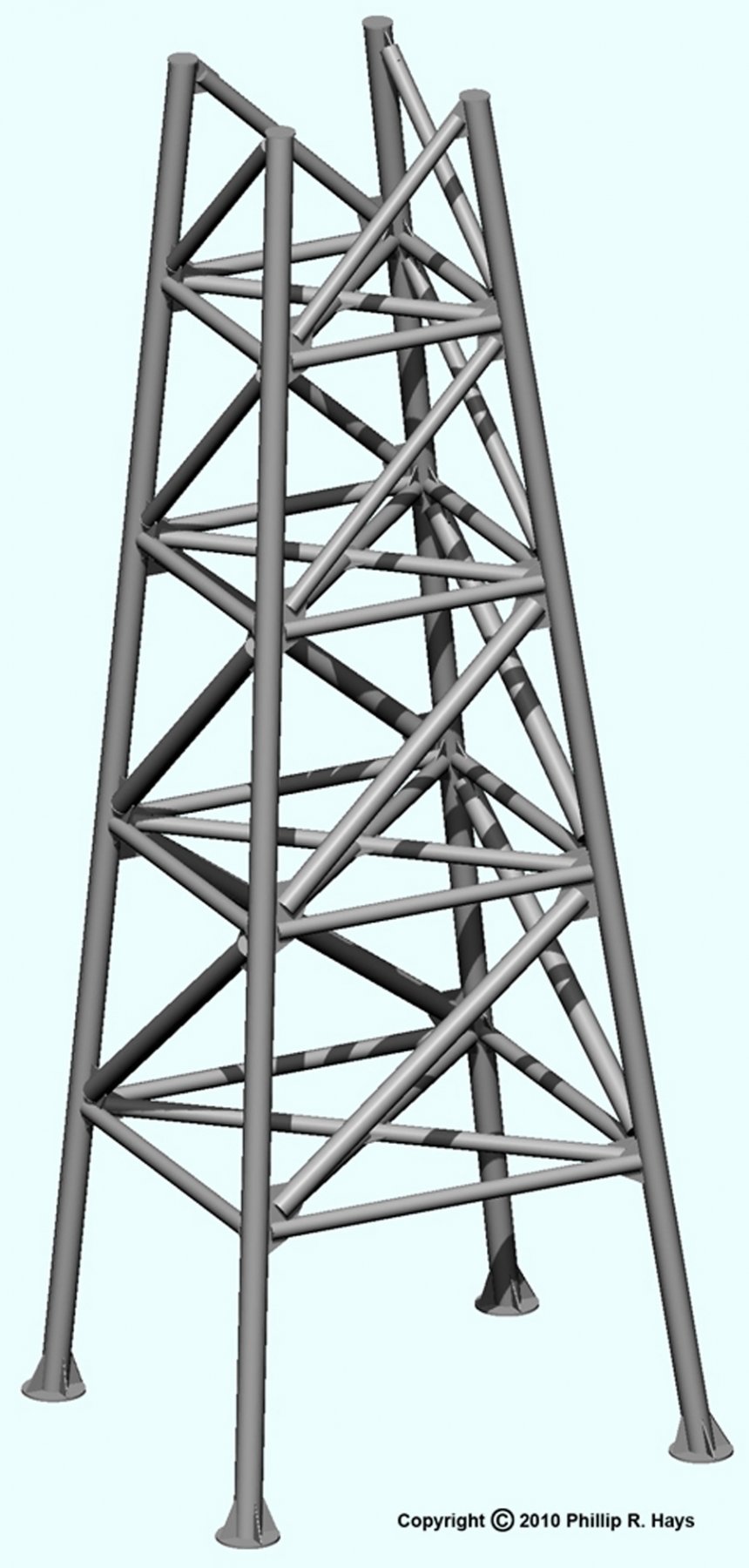
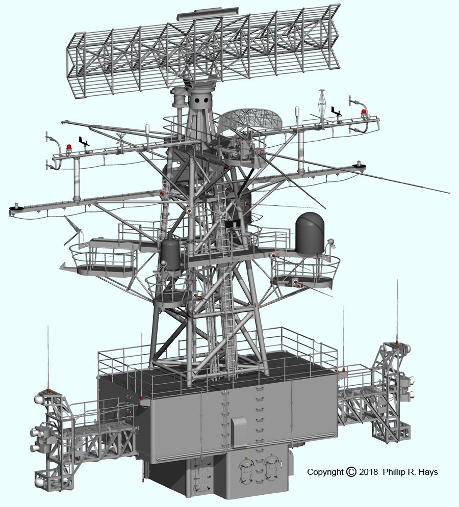
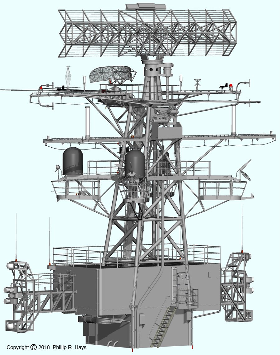
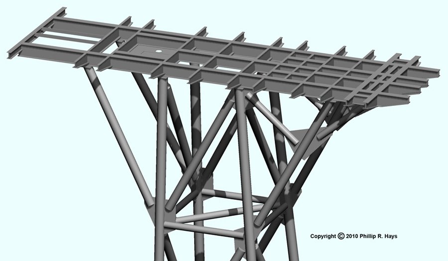
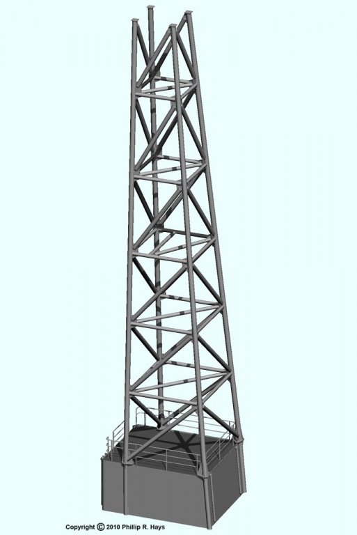
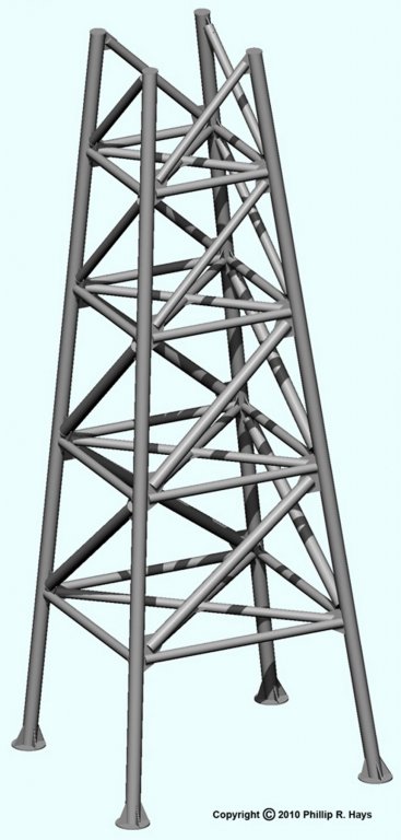
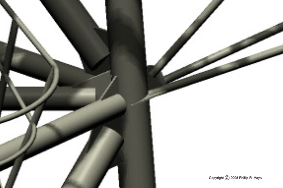
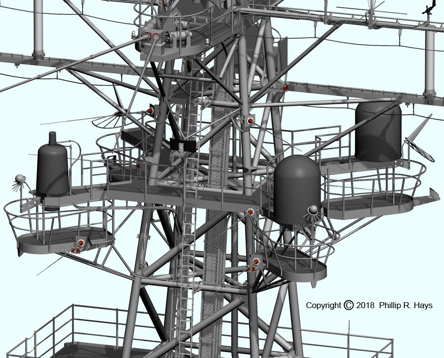
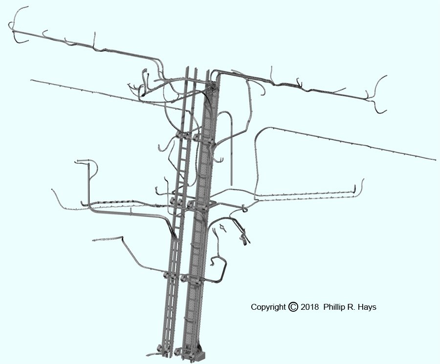
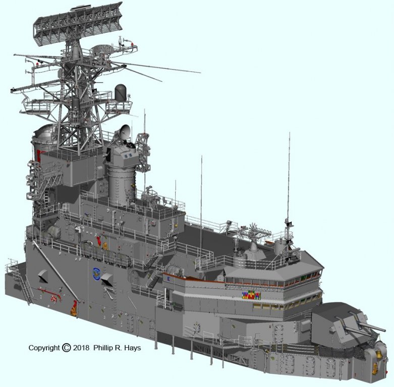
FORWARD RADAR TOWER I think the first part of the ship I modeled in 3D was the forward radar tower, in 2007 and 2008. The blueprints showed side and front views, with elevations. But the main tubes were angled inward side to side and front to back, so they were longer than the 2D views showed. I could have used 3D trigonometry to calculate the actual lengths, but I realized it would be much quicker and more accurate to model the tower in 3D. Besides, the last time I studied 3D trig was in celestial navigation classes in Officer Candidate School, and that was a long time ago. I don't remember much, and I certainly wouldn't trust my navigation skills (or trig results) today! Counting the main structural members and additional support tubing, as many as a dozen pipes and associated gusset plates came together in some places. I could imagine wasting a lot of time and materials in frustrating attempts to get all the tube lengths right. The 3D CAD model made it easy to figure out the dimensions. And from the model I can determine the 3D angles that all of the parts fit together to make construction jigs. Well, that's the plan. We'll see how I feel about it after I try to put all the pieces together. It looks like it might be a perfect job for 3D printing! The most complex part was the "cloverleaf," a collection of platforms to support some of the electronics counter-measure (ECM) antennas. Again, the blueprints gave plan views, and I had many photos of this structure, but it really helped to be able to put the pieces together in the CAD model. This was especially true because there were many blueprint sheets for the different parts, but no single sheet showed how they all fit together. And, of course, there were some changes to the original 1959 configuration by 1971. After my initial modeling efforts I discovered many additions and changes to the parts of the tower over the years. In 2015 I took up the task again. I included the O5 and O6 level compartments to the tower model because so many details of the tower continued down to these levels. Together they made a single module that was easily stacked upon the lower deck houses. The real impact of my decision to model all of the wiring and plumbing on the ship really came home on this tower. There are 38 antennas on the tower itself, and another dozen on the ECM shack and the outboard platforms (I obtained data sheets with dimensions for nearly all of the antennas). Those 50 antennas all had cables or waveguides running up cable trays and fanning out to the individual antennas. In addition, the ship had a water washdown system designed to spray sheets of water from sprinkler heads to catch radioactive fallout and wash it overboard. The washdown system was shown in the blueprints, but I had to depend upon photos to show how the wiring was routed. The wiring and waveguide routing was very complex (left above). I spent hours scrutinizing many photos to figure it out. Fortunately, while I was aboard the ship I wandered around taking pictures of various parts of the ship in case I might someday want to build a model of it (I have been modeling ships since I was a kid). I also had some photos other crew members sent me over the years, and some off the Internet. Often these photos were of crew members working or lounging at various places on the ship, with really useful background information in them. The washdown system piping (above right) wasn't as complex, but I had to assemble it with a collection of pipe fittings and mounting brackets as shown in the blueprints. As usual, there were a few minor changes in the configuration between the 1959 blueprints and the mid1971 period I was modelling. Otherwise it would have been far too easy! The ECM platforms outboard of the O6 ECM compartment (left) were fairly complex, and because they were added later they were not shown in the blueprints. More "photoguestimation!" But I have several good high resolution images of these structures, often in the background of photos of other things. At the top of the tower were the AN/SPS-43 long range air search radar antenna and the AN/SPS-10 surface search radars. I will discuss the ship's radars in detail in another post. Phil


- 48 replies
-
- 5
-
-
- 3d cad
- cleveland class
- (and 1 more)
-
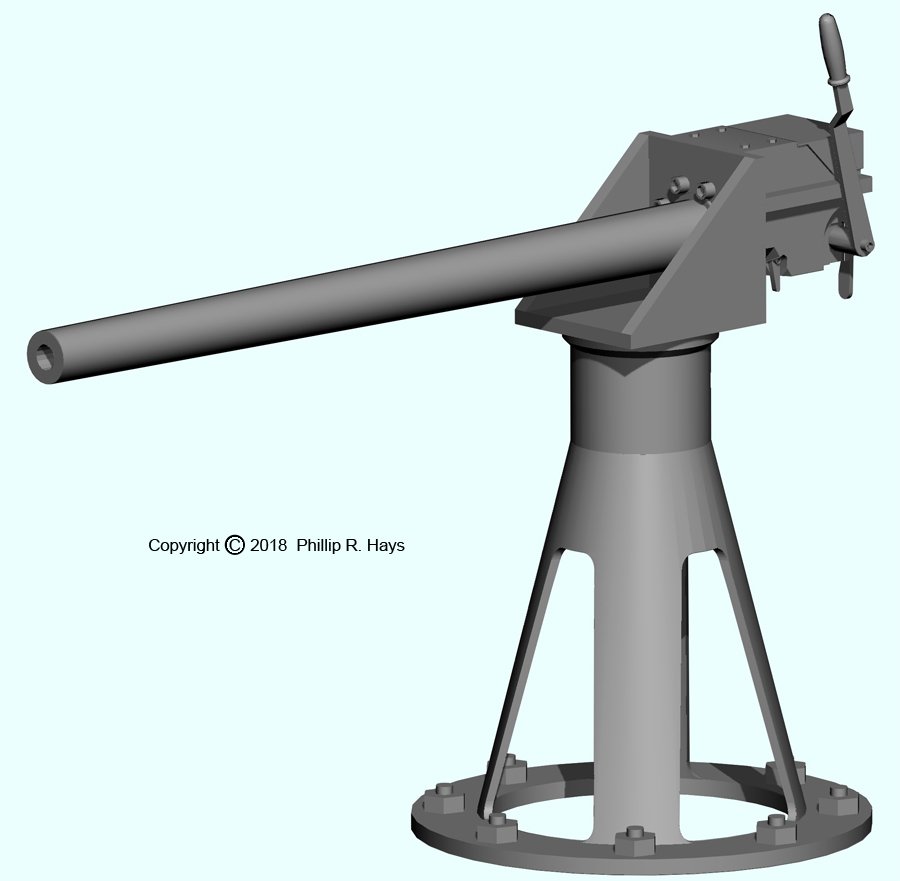
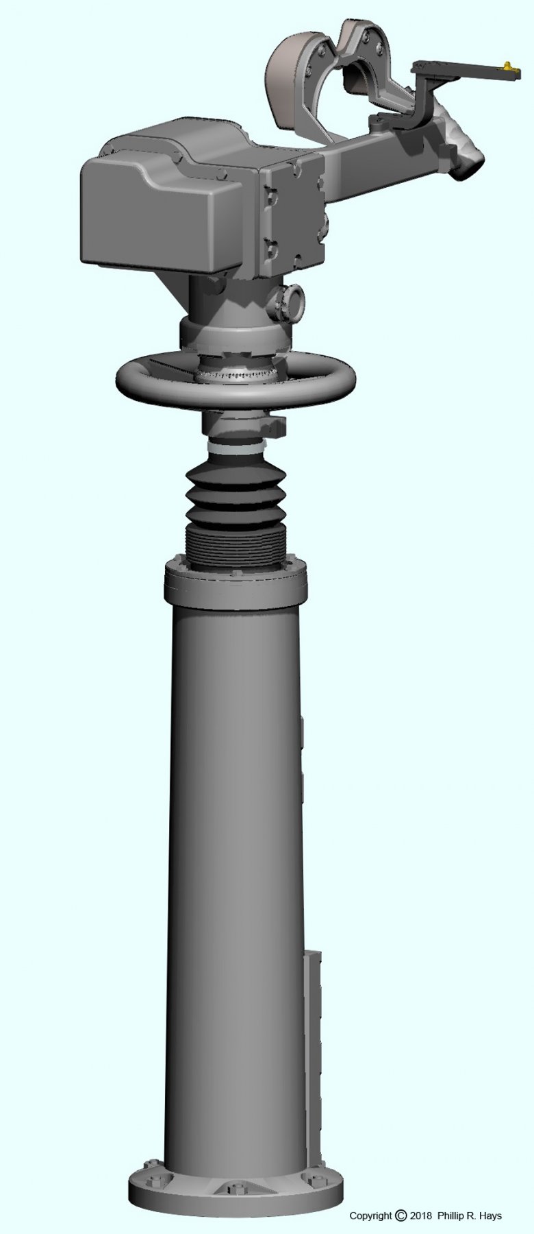
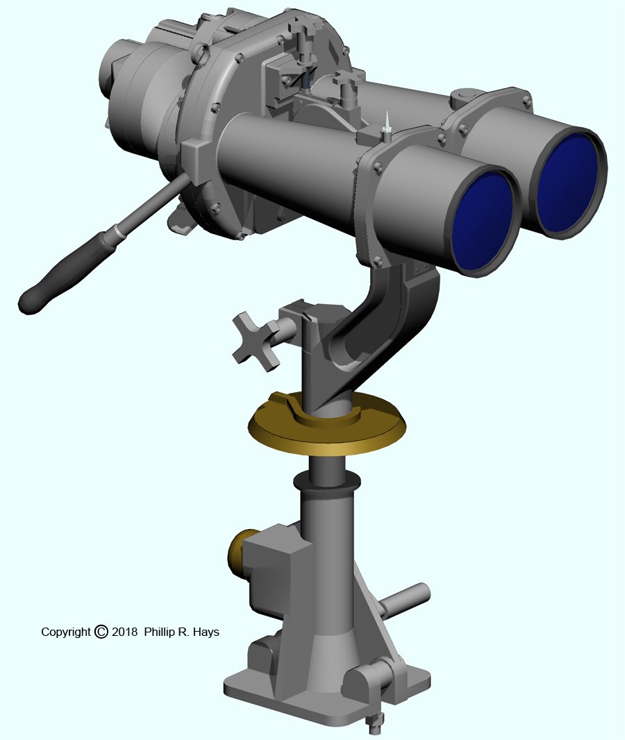
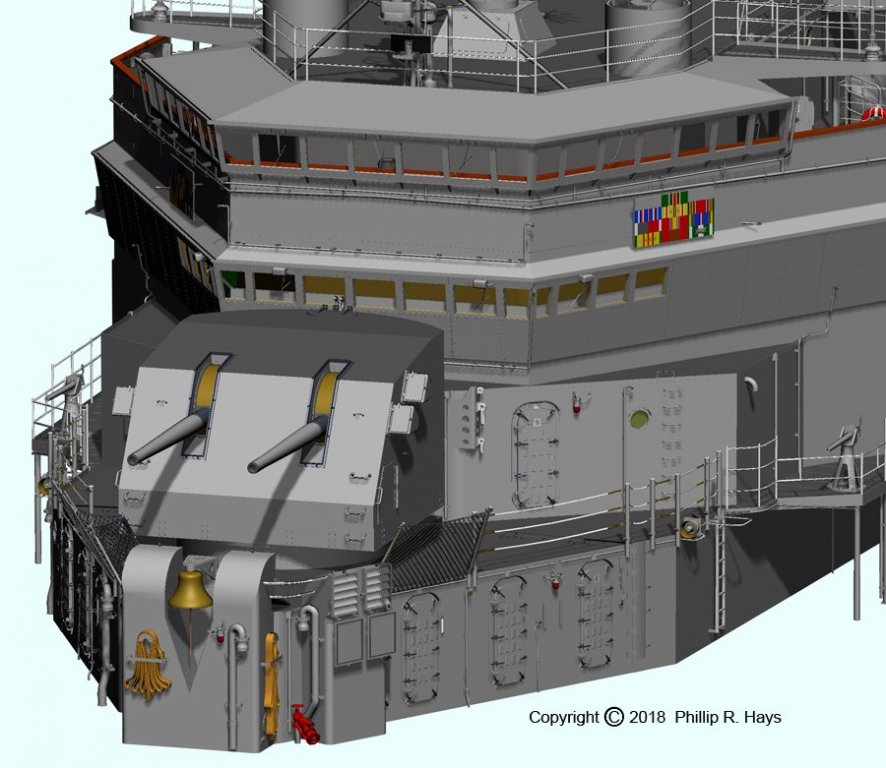
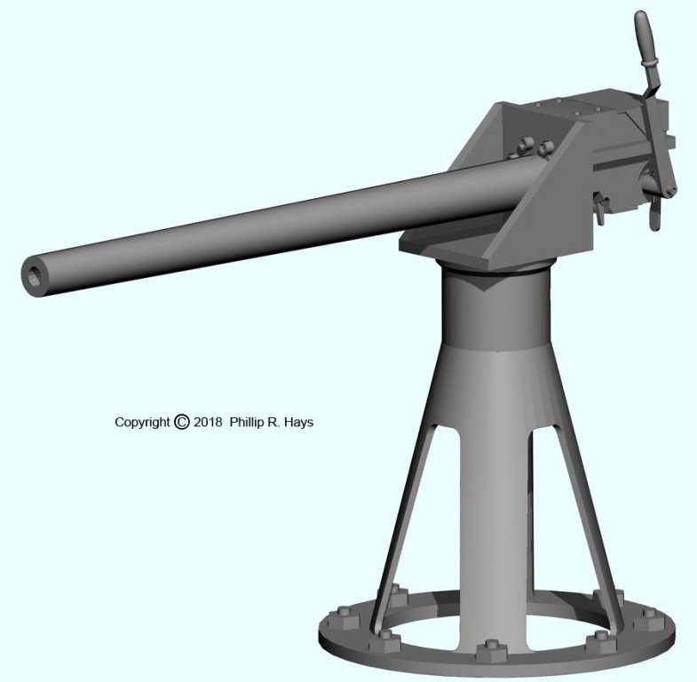
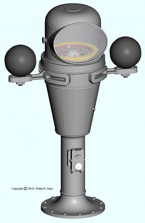
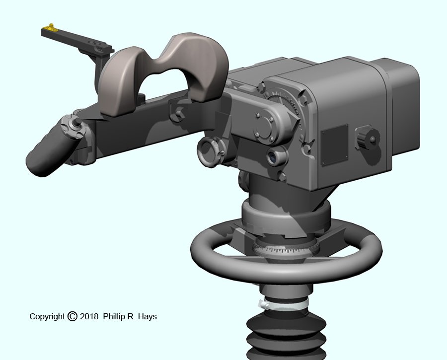
FORWARD DECK HOUSE When CL-91 was converted to CLG-5 most of the structure above the main deck was removed. For the forward superstructure only a narrow deck house remained from the main deck to the O5 level, including the original Mk 34 man battery director and Mk 37 secondary battery director. The original smoke pipe (funnel) and the O1/O2 level superstructure under it also remained. Then the huge new forward superstructure was built around this original core. The forward deck house was the one of first parts of the CAD model that I started, and almost the last part to be finished. Initially I just wanted to see how all of the decks and house sides fit together, something that was hard to visualize from the blueprints alone. The initial 2008 models are shown here. The OK City had many changes over the years. One of the most visible was the removal of the Mk 34 main battery director and its barbette from the top of the forward superstructure. When it was removed the O5 level deck house was cut back to a few frames forward of the Mk 37 secondary battery director barbette. But a few years later the O5 deck house was extended a bit. None of this was shown in the blueprints and I had to work from photographs to figure out these reconstructions. Another significant change was the addition to the large ECM compartment at the O7 level, extending outboard of the O5/O6 deck house. The original CLG build did not have a deckhouse at the O7 level forward. Then a small ECM house was added between the pipes of the forward radar tower. Later this was expanded to the wider ECM compartment shown here. The Oklahoma City had a huge ECM array that allowed the ship to redirect incoming surface-to-surface missiles, detect and track radio and radar emitters, interrogate Soviet built IFF transponders and even detect enemy aircraft engines running while the planes were still on the runway. Several smaller changes occurred over the years. At the port aft corner a new house extension was added at the main deck level. Then a few years later a similar house extension was built at the starboard rear main deck level. Some of the windows on the O2 level Flag Bridge were covered to create new office space inside, and then new compartments were added outboard on the O1 level below the Flag Bridge wings. Finally, the open bridge was enclosed shortly after the ship was commissioned. I had to piece together all of these details and the CAD model seemed to me to be the best way. Eight years later I was putting the finishing touches on the forward deck house. At first it looked relatively simple compared to the aft and midships deck houses I had already finished. But there actually was a tremendous amount of detail on this structure. One of the most difficult parts to model was the Forward Air Control station on the O5 level forward of the Mk 37 director barbette. The 1971 configuration bore little resemblance to the 1959 blueprints. After the Mk 34 director was removed Forward Air Control was completely rebuilt. And then the O5 deckhouse was extended Forward Air Control was rebuilt again. I had to work from photos, and that was a problem. I found several pictures taken from the O5 level - it was a high place with a good view. But no one took pictures of the O5 level! I had only a couple of fairly high resolution photos to work from. I had a few good pictures of the bridge wings and the forward O4 level for the 1971 period. Here are pictures of some of the details on the forward superstructure. The Mk 32 dual 5"/38 gun mount #51 was a carry over from the WWII configuration. The Clevelands got a mixture of versions depending upon what was available at the time of construction. The Mk 32 has the internal training stop buffer. Other Marks had the buffer on the front exterior of the mount. Clevelands had gun house shields made of 3/4" thick Specially Treated Steel (STS) plating. Destroyer gun houses were made of 1/4" plating to reduce weight. Some battleships had 2 1/2" thick shields on the 5" mounts. Mount #51 was removed when the original CL-91 superstructure was cut back. It was then repositioned on the O1 level of the new superstructure at approximately where the #2 6"/47 turret had been on CL-91. The Mk 37 director and barbette had quite a lot of details to model. The director originally had a perforated reflector dish, but this had been replaced with the solid dish shown here by 1971. I stood Director Officer watches in Vietnam, sitting in a chair under the folding canvas cover (it was folded back while the position was occupied). The inside of the director was like an oven, so the other three guys and I spent most of the time sitting on top and catching some rays. It was the highest manned position on the ship and we had a great view of the show. Getting into the director could be an adventure. We could enter the barbette through the door at the O5 level and climb a ladder inside to the director, but it could be pretty hot inside the barbette. Most of the time we climbed the ladders on the outside of the barbette, walked around the foot rings to reach the ladder on the side of the director, and climbed that. But if the ship was rolling a lot you really had to hang on, and if the director was rotating it was pretty tricky. The saluting gun was another modeling problem. I found very few photos to work from. By looking at web sites for other ships and even publicity photos from John Wayne movies I found enough to work with. The saluting guns were positioned at different places on the forward superstructure of the different CLGs. Since we were a flagship and showed the colors in many ports, these guns got a lot of use. They fired 37 mm blank rounds that just made noise and smoke. The searchlight and binnacle show more of the details on the superstructure. The image of the binnacle shows the transparent glass window with the compass card inside. However, on the whole superstructure model I removed the glass. If you put a transparent object in the file, when it is rendered every single part of the model has to be checked to see if it, or its shadow, can be seen through the glass. This increases the rendering time exponentially as the number of objects in the file increases. On one part, that normally took about 5 minutes to render, adding a single small transparent piece of glass increased the rendering time to about two hours! If I included the glass in the binnacle and the bridge windows I doubt that the universe would last long enough to complete a render of the forward superstructure! The Mk 23 Mod 0 Target Designation Transmitter (TDT) was another mystery. The ship had two of these in the Forward Air Control station on the O5 level. However, they always had bags over them in every photo I found. For the longest time I didn't have a clue to what they were. Then a fellow who volunteers to work on the USS Little Rock CG-4 museum ship in Buffalo, New York, sent me some photos of the units on that ship. Thanks to him I could make a pretty detailed model of the TDT. These things were WWII era aircraft tracking devices. A pair of binoculars were mounted in front of the head rest. The operator turned the mount and raised the arm with the binoculars to point at a target. Then he pushed the button in the hand grip at the end of the arm to designate the target for the gunfire control computer. By the Vietnam era fast moving jets and missiles made these obsolete. I don't know if they were ever used while I was aboard. The images below are the ship's Kollmorgan 20x120 binoculars. We had lots of binoculars, but these huge "battleship" binoculars were the ship's binoculars. There were mounts on both the port and starboard sides of the O4 level, near the skivvy waver's (signalmen) stations. These were really good optical instruments. They were normally stored inside and brought out only when needed. However, sometimes when we were in a busy port like Hong Kong these would be mounted, and it was interesting to use them to watch all of the traffic coming and going in the harbor. I had a few moderate resolution photos showing these devices in place on the ship, but I found some great photos on eBay! The AN/SQM-6 antenna was used to receive weather satellite information. Phil


- 48 replies
-
- 4
-
-
- 3d cad
- cleveland class
- (and 1 more)
-
Dennis, I have just looked through you Swan build and it is beautiful. I have thought about learning Blender. It is more of a drawing tool for producing nice images, and your work certainly shows it off well. But your comments help to emphasize the differences between drawing programs like Blender and Rhino and CAD programs like DesignCAD and Solid Works. Only the very expensive programs like Solid Works have any significant rendering capabilities. The inexpensive DesignCAD program has very poor rendering capabilities - basically just shadows with multiple lights. However, it can "map" textures onto surfaces, such as wood grain, concrete, etc. It can also "map" photos onto surfaces to make pictures hanging on walls of architectural designs. But without ray tracing we can't make mirrors, chrome metal, etc. I don't use texture mapping because it causes the program to run much slower, and really doesn't add anything useful for what I am doing. CAD programs work with exact dimensions, and have extensive tool sets for this purpose. They are intended to produce either physical 2D engineering drawings or 3D parts from NC machines or 3D printers. The program will convert any 3D view on screen into a 2D drawing for printing on paper. One of the next steps for me is to use the 3D model to produce 2D dimensioned drawing sheets for all the parts of the ship. That will take a while! Some fellows use DesignCAD to create mechanical drawings, architectural plans, etc. in 3D and then produce the 2D drawings. Then they export the 3D model to another program like SketchUp and use it to produce realistic renderings. One of my long term goals is to use the CAD model to produce walk-around videos. I think I'll need a lot more computing power to accomplish that! Phil
- 48 replies
-
- 1
-
-
- 3d cad
- cleveland class
- (and 1 more)
-
Swan class 3D model in progress
Dr PR replied to dvm27's topic in CAD and 3D Modelling/Drafting Plans with Software
Beautiful work! Just thinking about that rigging makes me shudder - I hate tying knots in CAD! You are a glutton for punishment. Phil- 104 replies
-
- 1
-
-
- pof swan series
- swan
- (and 1 more)
-
Valeriy, The level of detail Vladimir has put into his 1:200 model is exceptional! I can see he is still working on a few details here and there. One thing I did notice is that all of the whip antennas on the fore tower are long. In fact only the two at the top that project in a "V" from the top platform were the NT-66047 35 foot whip antennas. I think the rest were 10 foot AT-252/SR antennas. Note: The "Antenna Group" for the 10 foot antennas was AN/SRA-17, and that is what is listed on some lists of ship's antennas. But the antenna was the AT-252/SR. It was mounted on top of a box containing an antenna tuner. Together they make up the SRA-17. Also, the actual length of the antenna and insulator base was 10.5 feet. Phil
- 48 replies
-
- 2
-
-
- 3d cad
- cleveland class
- (and 1 more)
-
Valeriy, Tell Vladimir his work is beautiful! Of course, I am not biased ... I examine models of the Okie Boat with a very critical eye, and his details are spot on! I am glad he has painted the tops of the smoke pipes and towers black like they were on the real ship. I made them gray so the details would be visible in the CAD images, but eventually I need to make them black. Several other fellows have said they were working on a model of the ship, but these are the first photos I have seen of a model built according to my drawings. Thank you very much for posting them! I hope my 1:96 model looks as good. How long has he been working on this model? If you or he (or any one else) have questions please contact me by email through my web page https://www.okieboat.com/Contact page.html Phil
- 48 replies
-
- 4
-
-
- 3d cad
- cleveland class
- (and 1 more)
-
Fellows, Thanks for the comments. Actually, I'm glad you didn't say I am crazy for taking on such a lengthy project! Phil
- 48 replies
-
- 2
-
-
- 3d cad
- cleveland class
- (and 1 more)
-
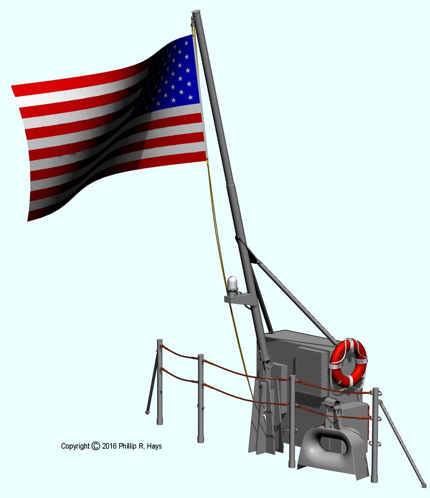
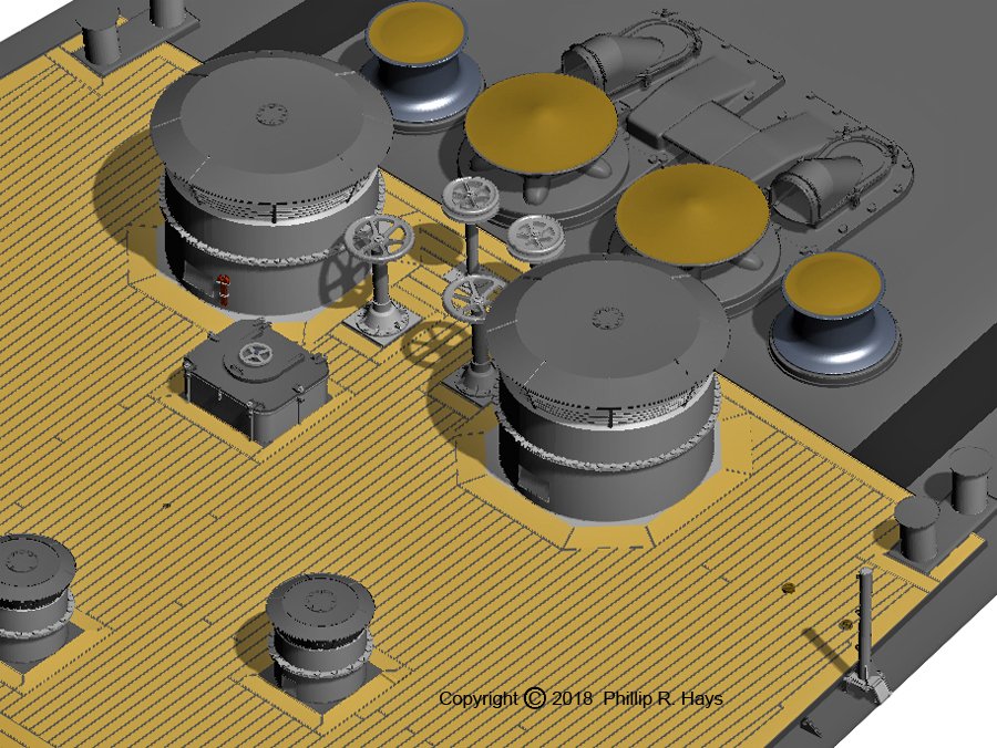
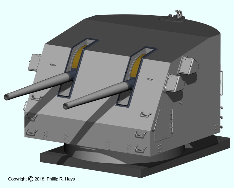
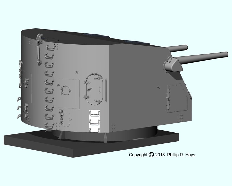
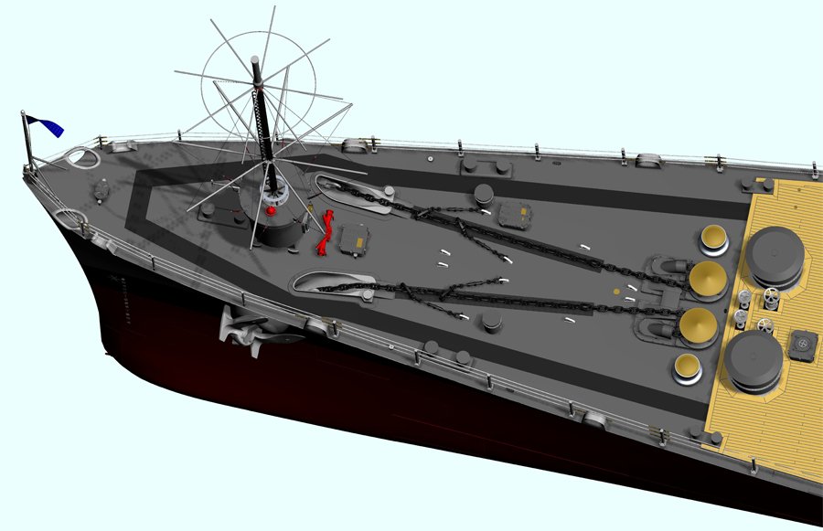
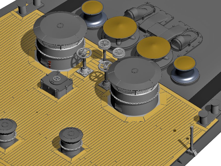
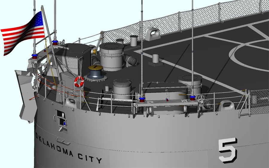
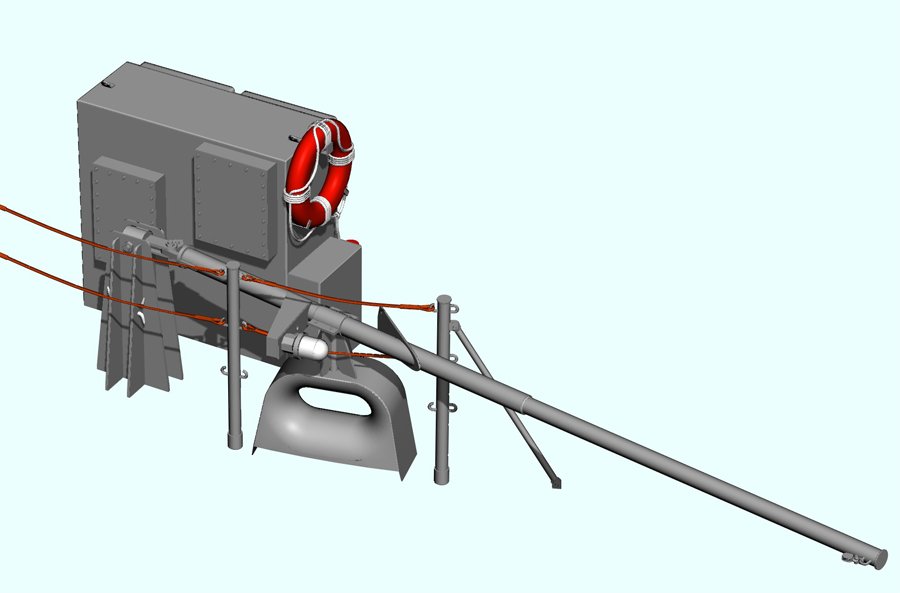
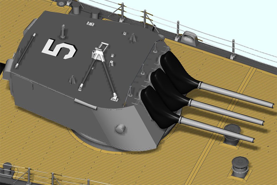
THE MAIN DECK I consider the main deck to be part of the hull, but it was constructed separately in the CAD model. Most of the equipment and fittings on the fo'c'sle were original 1940s Cleveland class parts. The two 20mm gun tubs had been removed and a large discone antenna took their place. Originally the OK City had the antenna mounted on a short open lattice tower, just like the configuration of the USS Little Rock CG-4 museum ship in Buffalo. But the tower was enclosed later in a cylindrical compartment that was used to stow anchor handling gear. The sailors called this cylindrical structure the "beer can." The original 1960 CLG discone antenna was replaced a few years later with a larger version with more elements. The two "wildcats" were large sprockets that fed the anchor chain into and out of the chain pipes to the chain lockers below. These and the brake controls, plus the capstans and their controls, were original equipment. The blueprints showed all of the anchor equipment, above and below deck, in great detail, and even told how to operate it. Some ships painted the chain pipes red on the port side and green on the starboard, but they were deck gray on the Okieboat. The Captain said he didn't want his ship to look like a circus boat! The blueprints gave only a rough outline of the changes to the wooden decks for the CLG conversion. I had to depend upon a dozen or so high resolution photos to see how it was done. But the original CL blueprints told how the planks were fitted together, and the CLG photos showed that the new deck was assembled in the same way. The deck planks were 2"x4" and 18 feet long originally. Most were cut to 16 foot or shorter lengths when they were installed. Plank ends aligned with the ship's frames at 4 foot intervals. The planks were a laminate of 1" of teak on top over 1" of Douglas fir on bottom. They were bolted down to threaded studs welded to the deck plates, with the nuts fitting into recessed cavities that were filled with white lead and then sealed with a teak plug. I didn't try to model the plugs! On the original Clevelands the wood deck extended forward to just in front of the #1 turret. Perhaps this was to minimize flash burns from the firing of the 6" guns. On CLG-5 the wood deck was extended forward to just behind the wildcats and capstans. Some of the other CLGs also had some sort of wood deck extension, but not all were like the OK City's. On the CLGs the wood deck extended aft only to about midway down the side of the missile house. The Talos missile boosters produced a 60-70 foot flame that could flash up the side of the missile house if the shot was fired almost directly aft. This would have burned the wood deck. As it was we had to repaint a large portion of the metal deck after each shot. Margin boards 9" wide were fitted around the deck edges, around the superstructure, and around hatches, vents and other deck fittings. The margin boards were 2 1/2" thick along edges next to deck house and hatch sides, and were trimmed to 2" where the deck planks joined - this caused water to flow away from the house sides. If the deck planks joined the margin boards with an angle between 45 degrees and 90 degrees the planks were trimmed to fit the margin boards. But if the join angle on the plank was less than 45 degrees the deck planks were notched into the margin boards so the planks didn't have sharp pointed ends that might break off easily. The nibs were cut perpendicular to the length of the planks, and were half the plank width. The minimum width of the margin board at the notches could not be less than 6". There were lots of planks and joins. It took a month or two to create the wooden deck. I'm not sure I look forward to repeating this on the real 1:96 model! The stanchions along the edge of the main deck were articulated affairs that could be folded down to lower the life lines during underway replenishment. In practice during UNREPS the stanchions and lifelines were just removed to get them out of the way. The ship had a 15" wide waterway between the wood deck and the hull side. The stanchion base was welded to the top of the hull plating and to a 3/8" flat bar that bordered the wood deck. But the height of the hull plating above the main deck and the angle of the hull plating varied along the length of the ship. Consequently, no two stanchion bases were the same and I had to fit each one separately. At the bow and stern, where there was no wooden deck, some stanchion pipes fitted into cylindrical pipe sleeves welded to the deck. There were 20 different stanchion configurations. The stanchions were mostly the same type on opposite sides of the ship, but there were a few differences. The bitts and chocks on the CLG were mostly in the same positions as for the original CL hull, but there was one interesting difference on the Okie Boat. The bitts were standard 14" bitts that were used on cruisers. But the USS Oklahoma City CLG-5 had two 10" bitts on the fo'c'sle outboard of the capstans. The wood deck was trimmed around them. The OK City was the only Cleveland class ship, CL or CLG, that had these smaller bitts. Almost everything on the fantail was new after the CLG modification. The airplane hanger, aircraft crane and catapults were removed, as were the two aft 6"/47 turrets and 40mm gun tubs at the stern. These were replaced by the Talos missile launcher, a helo deck and several ventilators at the stern. The helo deck had fold down life nets at the deck edges - these were very tedious to model! The tall whip antennas also folded down for flight operations. They were originally on top of the large "D" shaped ventilators, but were later lowered and moved outboard. The flagstaff on the stern was one of the most difficult parts to model. It was raised in port - except when we were conducting flight operations - and folded down and clamped in a fixture on one of the chocks when we were at sea. The ship had at least four different flagstaffs! The CL and CLG blueprints showed two configurations and early CLG photos showed a third. But I could see from photos that the flagstaff of 1971 was different, but the photos were too grainy to tell just how it was constructed. One day I was looking through the cruise book and noticed a photo of a sailor standing stern lookout right beside the life ring that was attached to the electrical cabinet. The flagstaff was lowered and I could see details of the fixture on the chock and how the staff was fastened down. Then someone sent me a nice high resolution photo of a ship docked at a pier in the distance, with the stern of the OK City at the edge of the photo. There I could see the base of the flagstaff! That allowed me to finish the model of the flagstaff, and I think this configuration was still there at decommissioning in 1979. The staff itself was easy to model - the original USS Oklahoma City CG-5 flagstaff is outside the American Legion Center at Newport, Oregon, about a hour from my home. There were a number of winches and smaller fittings on the main deck but I will discuss them in a post about the ship's boats and boat handling gear. The last large feature of the main deck was the triple 6"/47 turret. The Clevelands had four of these turrets. Only the forward turret #1 remained after the CLG flagship conversions. The blueprints showed the construction of the turret gun house, barbette, and projectile and powder handling gear. But I have never found drawings of the 6" Mark 16 47 caliber guns. The early Clevelands had range finders on the #1 turret, but these were removed on later ships to reduce topside weight. The OK City never had the rangefinders on this turret. The Cleveland's #1 and #4 turrets had access doors on the rear. The superelevated turrets #2 and #3 had access doors on the bottom rear. A tripod was stowed on the turret top. It could be assembled for highline transfers on either side of the ship. We normally took on ammunition on the starboard side. The highline cable passed over the top of the tripod and fastened to the main deck on the side opposite the transfer ship. Phil

- 48 replies
-
- 7
-
-
- 3d cad
- cleveland class
- (and 1 more)
-
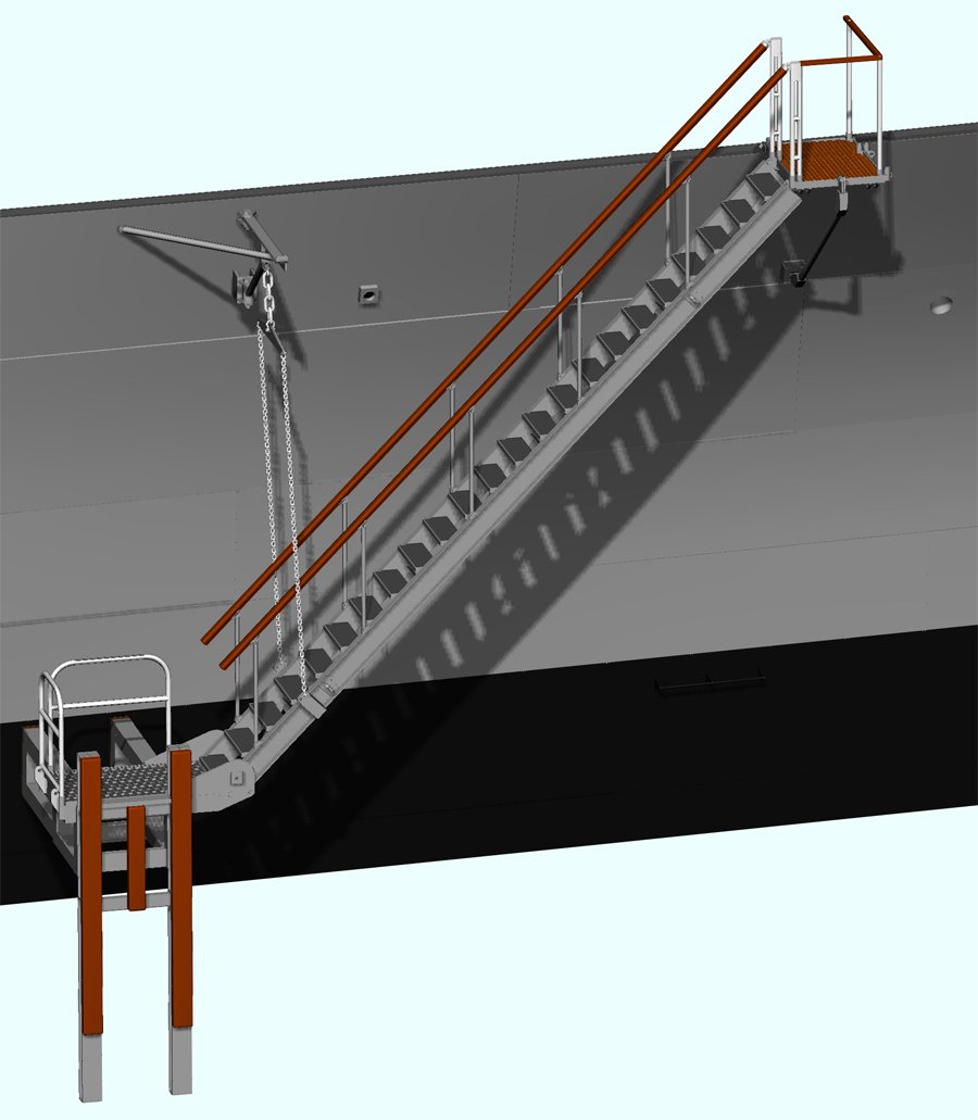
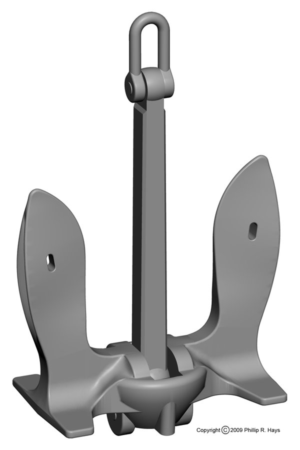
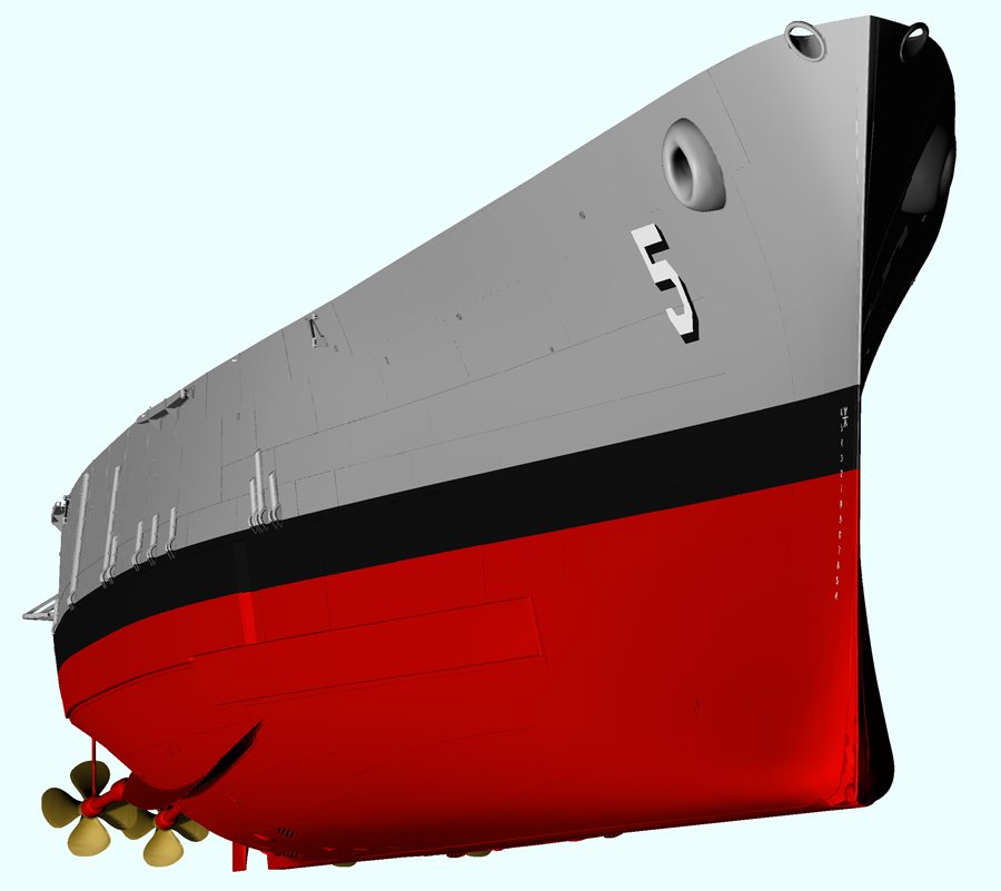
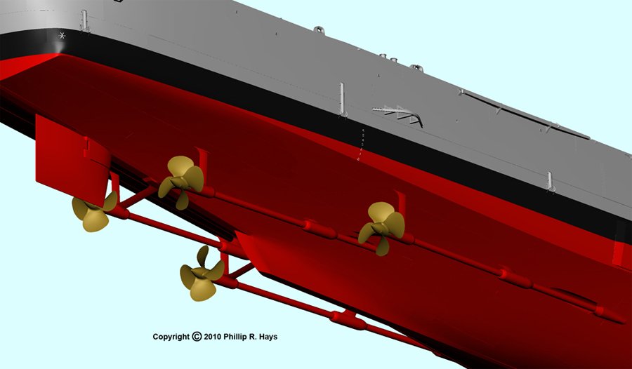
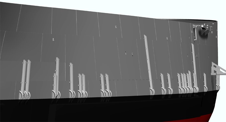
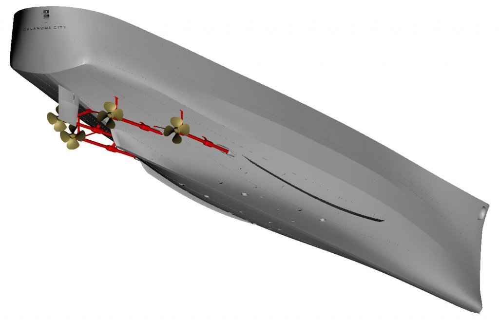
THE HULL, PART 5 The hull had a lot of details. Here are a few pictures. I had blueprints for the rudder, propellers, prop shafts and struts, propeller guards and boat booms, so they were pretty easy to model. Well, the propellers tested my ability to model complex curved shapes. My goal is to use the 3D file to drive a NC milling machine to make the 1:96 scale props. There are four different propellers, two right hand rotation and two left hand. In addition, the blades of the outboard props are slightly wider than the inboard props because they were positioned higher (not as deep in the water) where water density and pressure were a bit less, so the wider blades gave them the same thrust at the same RPM as the inboard props. The blueprints revealed something you don't see in photos - the propeller shafts entered the hull in recessed shaft alleys that had "portable" (removable) covers. The propeller struts were very interesting. The struts and hubs were single cast steel pieces. The after struts were about 12 feet long and the hubs were about 7 feet long and 2 1/2 feet diameter. After the struts and hubs were attached to the hull they were machined in place to be aligned with the propeller shafts! That would have been something to see. The inner diameter was about 2 feet and was machined to accommodate six cylindrical bearings that the shaft turned in. Along the side of the hull were many split pipe drain covers, with curved steel pipe bumpers to protect them. These covered overboard discharges from showers, toilets, etc. They were absent on the original 1944 hull, and were added during the CLG conversion. They caused quite a bit of consternation because no two photos of the ship show the same configuration! There were from 14 to 24 on the starboard side, and more on the port side. Some photos clearly show weld marks on the hull where a pipe and bumpers had been. Apparently they were occasionally ripped off, perhaps by heavy seas or contact with piers. In any case, I had to make a best guess about how many were on the ship in the July 1971 period I was modelling. The ship carried two accommodation ladders, one fore (officers) and the other aft (crew). They could be installed on either side of the ship. During the ship's career the ladders were changed at least twice. The blueprints showed the original CL ladders and the CLG ladders, but photos showed the 1971 ladders to be different from both. I had to piece together what they looked like from a combination of blueprints and photos. I don't intend to show them rigged, but I had to construct them in order to get all the pieces to fit together correctly. Then I placed the disassembled parts in the stowed positions on the superstructure. The hawse pipe and doughnut-shaped bolster were a challenge. The 2D blueprints tried to show the contours of the bolster but I had to scratch my head a while to figure out the 3D shape. Fortunately I had photos to work from, but it was still a challenge. I drew this in 2007 and learned a lot about drawing free form shapes! The surface is a single grid that wraps around into the hawse pipe. The anchor was another tricky job, with lots of intersecting curves that were interesting to model. The anchor stock was drawn up into the hawse pipe when stowed. When the anchor was let go the anchor chain payed out through the hawse pipe. The ship actually had two slightly different US Navy 13,000 pound anchors. One of the original anchors was lost on the 1945 shakedown cruise and had to be replaced. The first two Cleveland class ships, USS Cleveland CL-55 and USS Columbia CL-56, had the stern lights attached to the outside of the hull plating. The white stern light and blue formation lights were used for formation steaming, and the conical light was the wake light that illuminated the ship's wake. All subsequent ships of the class carried these lights in a recess in the hull plating that provided better protection from following seas. You would think that these lights would have been positioned along the ship's center line, and it looked this way in some photos. But others seemed to show the opening off center to starboard. The hull plating blueprints showed the opening but gave no dimensions and the position was still ambiguous. But the drawing referenced the blueprint for the stern lights so I searched for it on the microfilm. No luck! That particular drawing was not in the blueprint set! Arrggh! I eventually got the idea of looking at the blueprints for the hull framing, and sure enough the recess was offset to starboard. The reason was pretty obvious when I looked at the drawings - the original ships had a large airplane crane on the centerline at the stern, and the hull frame below it was a massive "I" beam. The recess fit up against that centerline frame. The drawings also gave the dimensions. Of course, after I did all that searching someone sent me a very nice photo of the stern that clearly showed where the opening was. Phil


- 48 replies
-
- 6
-
-
- 3d cad
- cleveland class
- (and 1 more)
-
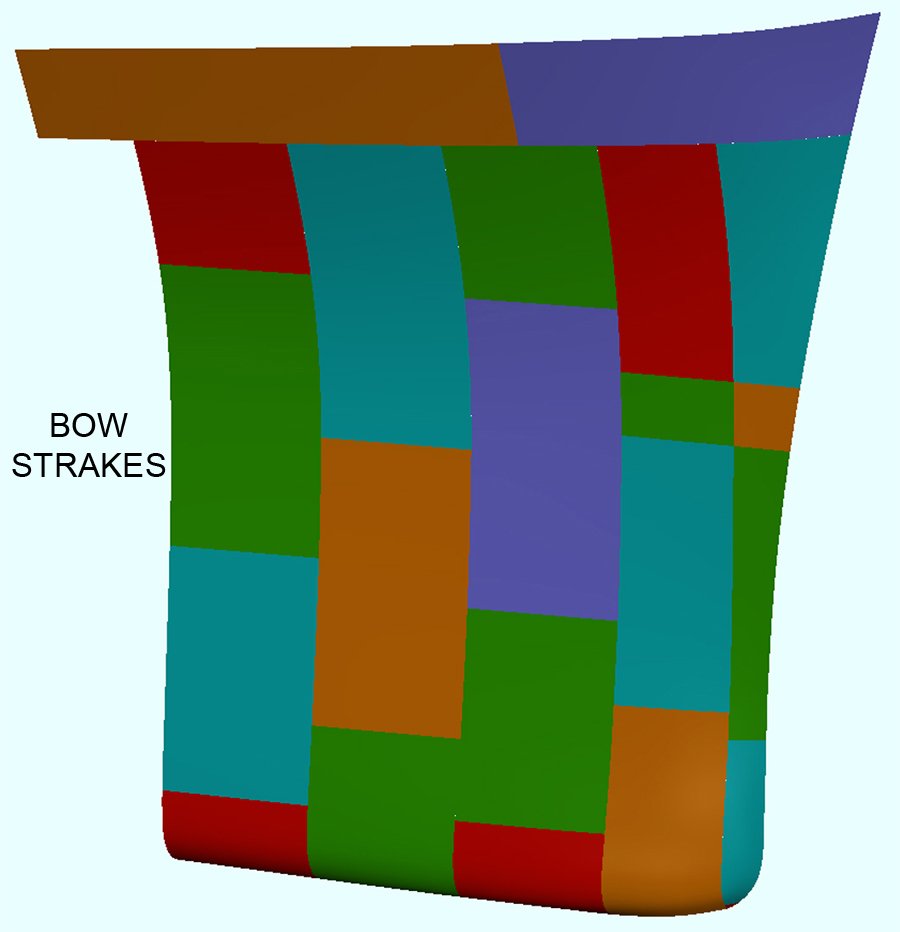
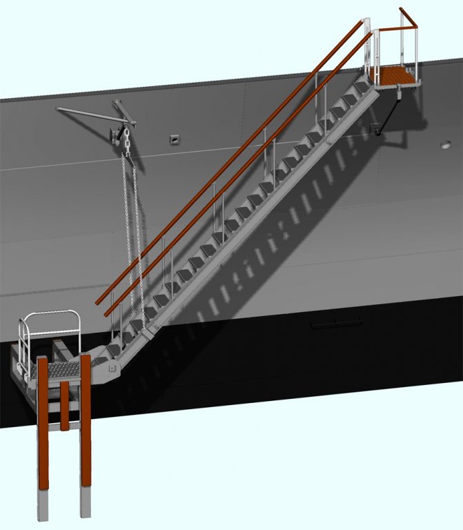
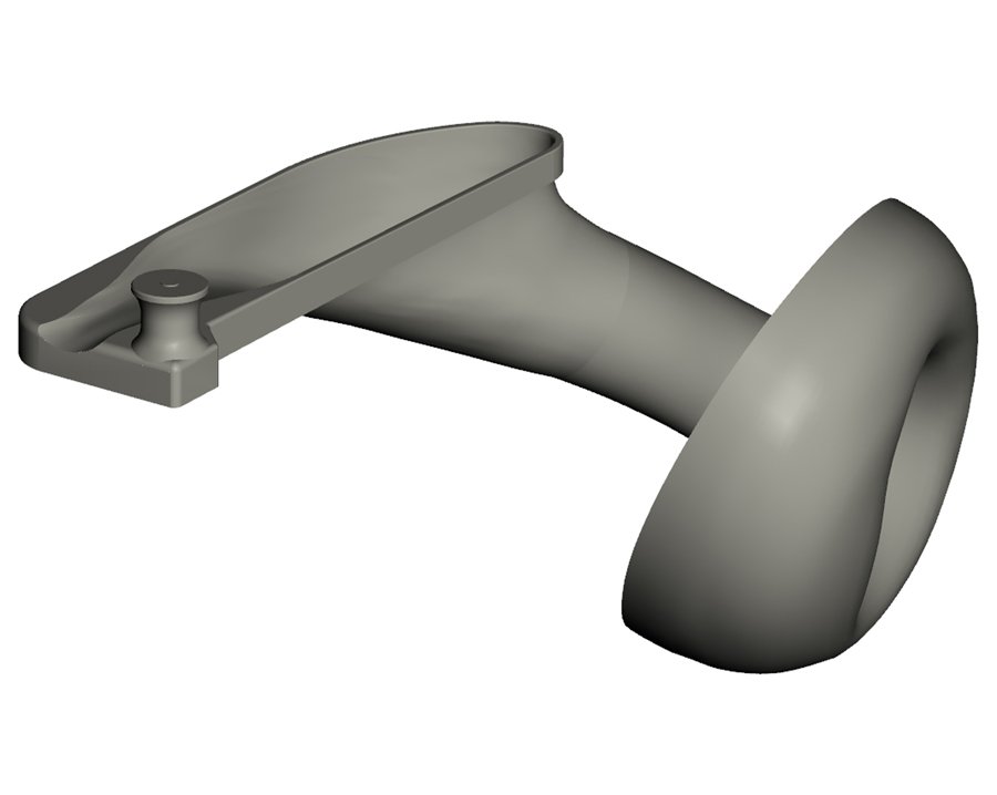
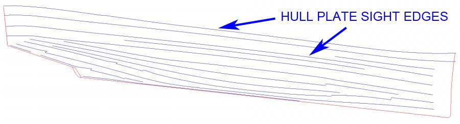
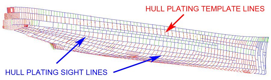
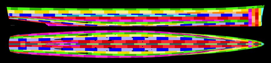
THE HULL, PART 4 I decided to start over on the hull to build it up plate by plate like the real hull. I have the blueprints that show the general arrangement and plate thickness. My plan was to use the original smooth hull and project the plate outlines onto it. Then I created individual grids for each plate, and built up the thickness to what was shown in the drawings. This turned out to be very tricky! Cleveland class hull plating was not the simple upper strake overlapping the strake below it that you see in many ships. Nor did it have alternating strakes with every other one on top of it's neighbors. One strake did overlap the strakes above and below. Some were overlapped by higher strakes and then overlapped the strake below it. Some were overlapped above and below. A few were just butted together edge to edge. And the plates were not all rectangular - some had more than four sides! To make matters more complicated the blueprints did not give dimensions for any of the plates, and one important blueprint was missing! I was pretty frustrated and thought about giving up on the hull plating. But then I fortuitously stumbled across the mold loft offsets in the microfilm set. There I found the Tables of Sight Edges, and that was the key. These were the familiar tables with hundreds of F-I-E numbers like the Table of Offsets. But these numbers told where the edges of every plate were to be positioned on the hull. Eureka! While the ship was under construction the builders used surveying techniques to position the plates according to the elevations in the sight edges tables. I used the data to create the sight lines, as shown in the picture. Then I projected these lines onto the smooth hull. The blueprints showed where the fore-aft edges of the plates were located at specific frames. That was all I needed to know to create the template lines for the plating. Below is a drawing of the hull plating configuration. Individual strakes are in light and dark shades of the same color. The two sides were mirror images except for the garboard strake (red) outboard of the keel and half siding. The garboard strake plates were different port and starboard to prevent alignment of seams on opposite sides of the keel. There were about 480 plates in 15 strakes. Notice the bow - here the strakes were vertical up to the upper strake. I had never seen this before, but it makes sense. I guess the bow was assembled in the yards and then moved into position in the ways. At the thinnest part of the bow (at the full load water line) one of the starboard side plates was added in two pieces. This allowed a workman to reach inside and finish the internal welding. Then the additional plate was added to finish the job. OK, so I knew where the plates were located, what their shapes were, and where the internal surfaces were on the hull. To finish the plating I had to build up each one to the proper thickness. Plate thickness varied a great deal, being thickest near midships and down low where water pressure was greatest. Steel plate is measured by weight, in pounds per square foot - for example 1" thick plating weighed 40.8 pounds per square foot, and was marked 40#. At the bow the sheer strake (main deck level) was 10# (1/4 inch) and the plating for the bulbous bow was 30# (3/4 inch) just above the keel. Midships the sheer strake was 35# (7/8 inch) and at the keel it was 28# (11/16 inch). The keel midships was 68# (1 5/8 inch) and 35# (7/8 inch) at the bow. Since the internal surfaces aligned plate to plate, where the thickness varied there was a step in the hull exterior surface. The blueprints instructed that after welding was complete, where plates of different thicknesses came together below the full load water line the high edges were to be ground back at a 45 degree angle to reduce drag. This was getting complicated! To add to the fun I wanted to model all of the hull openings (seachests). The microfilm contained lists of seachests telling the frames where they were located, but not giving the elevations. But the drawings showed where the openings were on each hull plate. And finally, there were blueprints for each seachest showing the dimensions and how they were attached to the hull. There were 32 seachests in the engineering spaces and a half dozen more scattered about the hull. Six months later I had the fully plated hull, complete with external backing plates above the water line, hull openings, rudder, propellers and shafts, stern light opening, armor belts, bolsters for the anchors, the eyes, boat booms, propeller guards, split pipe drain covers, and the odd doughnut shaped bolster on the stem for the WWII era minesweep paravane cables. Each of these features was a drawing in itself, based upon blueprints and photos. Phil


- 48 replies
-
- 6
-
-
- 3d cad
- cleveland class
- (and 1 more)
-
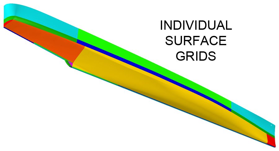
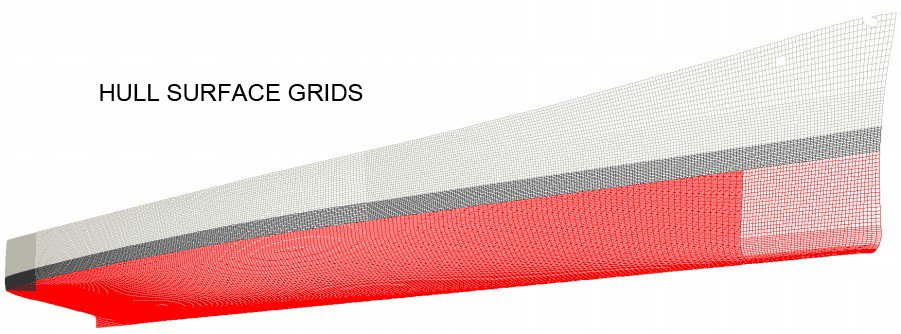
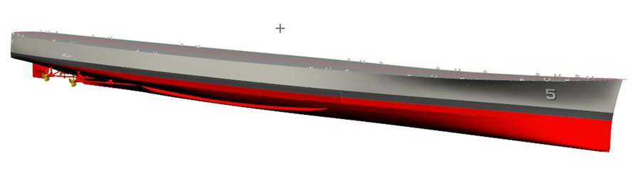
THE HULL, PART 3 The Cleveland class hull was far more complex than the 40 foot boat hull. It had a skeg like the smaller boat, but it also had a fairwater on the aft end of the skeg to reduce turbulence as water flowed past the skeg. It had knuckles, or sharp breaks to the smooth curves, at the third deck level just above the armor belts (they were attached to the outside of the hull plating). It also had a bulbous bow and a very complex transom that was semicircular at the main deck level and almost square below the full load water line. I used many different surface grids to cover the entire hull. Only the starboard half is shown - the port side was a mirror image of the starboard side. The hull was built up in three main groups, the upper hull, boot topping (water line), and lower hull. The upper hull is three grids light blue and green. The boot topping is three grids dark green and dark blue. The lower hull was the most complex shape and is made up of three grids, orange, yellow and red, plus several more for the keel and skeg fairwater . The yellow grid has a sharp knuckle near the top at the third deck level. The bow has some complex curvature to create the bulbous bow. The wireframe view of the grids is shown below. Notice the different grid densities (grid line spacing). For long and fairly smooth surfaces you do not need a lot of facets. But where surfaces are highly curved the grid must have many smaller facets. So why not just make all the grids with dense facets? This causes the file size to grow very large, and large files are much slower to work with. After a few more modifications and details like the propellers and shafts, the rudder and bilge keel I finished the first pass at creating the ship's hull. It was OK ... But while I was working on this I was also following some other CAD model builds on line. One model in particular, a destroyer escort by a fellow in Perm, Russia, really impressed me. He was adding small details that I had not planned to model, such as nuts and bolts, wiring and external piping. I sent him drawings of the quick acting watertight door and he returned a working CAD model! When the handle turned the dogs rotated and the door opened!! A model of a battleship included threads on the turnbuckles in the rigging. Another fellow modeled the entire internal frame and deck structure of the INS Yamato! WOW! This was setting the mark pretty high. I decided that if they could include such fine detail, so could I. That was a consequential decision! A 610 foot cruiser probably has five times as much external detailing as a 300 foot destroyer escort - I hadn't taken that into account. So my focus changed to including every visible detail on the ship's exterior, down to nuts, bolts, screws and rivets as small as 3/16 inch diameter. However, I did decide to leave out the threads on the bolts and screws - that would have made the file sizes ten times larger. After some preliminary work I decided to not model the internal frames of the ship. This called for a lot more detailed research, close scrutiny of a lot of photos, and accumulation of drawings and data sheets for small parts like antennas, binoculars, searchlights, etc. Creation of the model slowed to a snails pace. Phil
- 48 replies
-
- 7
-
-
- 3d cad
- cleveland class
- (and 1 more)