
HOLIDAY DONATION DRIVE - SUPPORT MSW - DO YOUR PART TO KEEP THIS GREAT FORUM GOING! (89 donations so far out of 49,000 members - C'mon guys!)
×


Dr PR
-
Posts
2,445 -
Joined
-
Last visited
Content Type
Profiles
Forums
Gallery
Events
Everything posted by Dr PR
-
 Valeriy, I seem to recall that after aluminum was discovered in 1825 the Czar of Russia had a helmet made of aluminum that contained almost all of the purified metal on Earth. Aluminum was valued at many times the cost of gold and the helmet was said to be one of the most valuable things on Earth! At first small specimens cost about US$160 per pound, Then new techniques for separating the metal were discovered. In 1855 Aluminum cost US$90 per pound. Then in the late 1880s mass production of aluminum began and the cost dropped to US$2 per pound. Then the modern electrolytic separation method was developed in 1889 and the cost per pound dropped to US$0.20, and was cheap enough to use in ship building. The value went from the most valuable substance on Earth to a fraction of a dollar in a little over half a century. Now that is deflation!
 -
John, Thanks. I could have omitted the swivel guns but I liked the guns on the Lady Washington. When the Syren parts turned out to be the right type and size I couldn't resist.
-
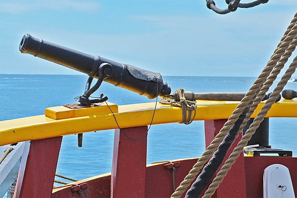
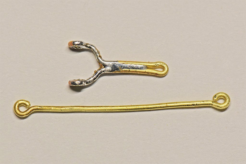
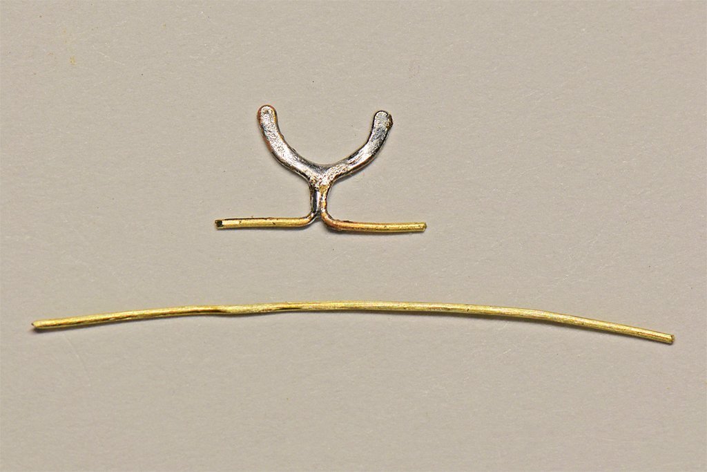
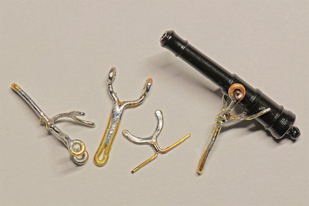
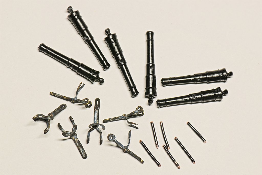
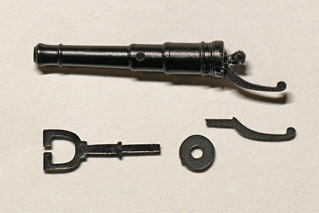
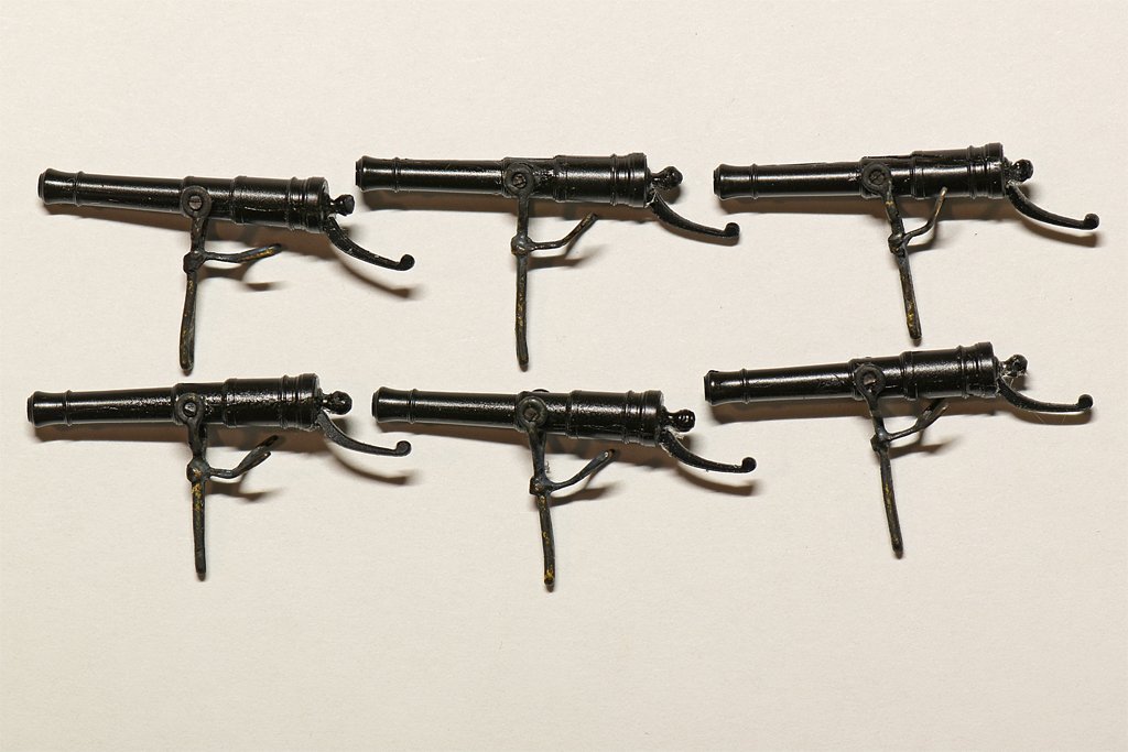
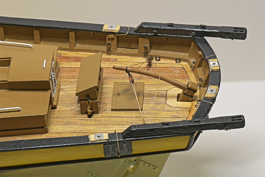
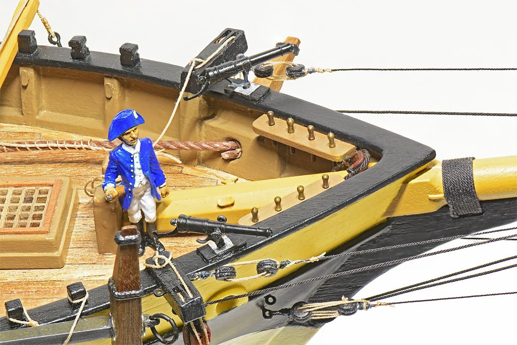
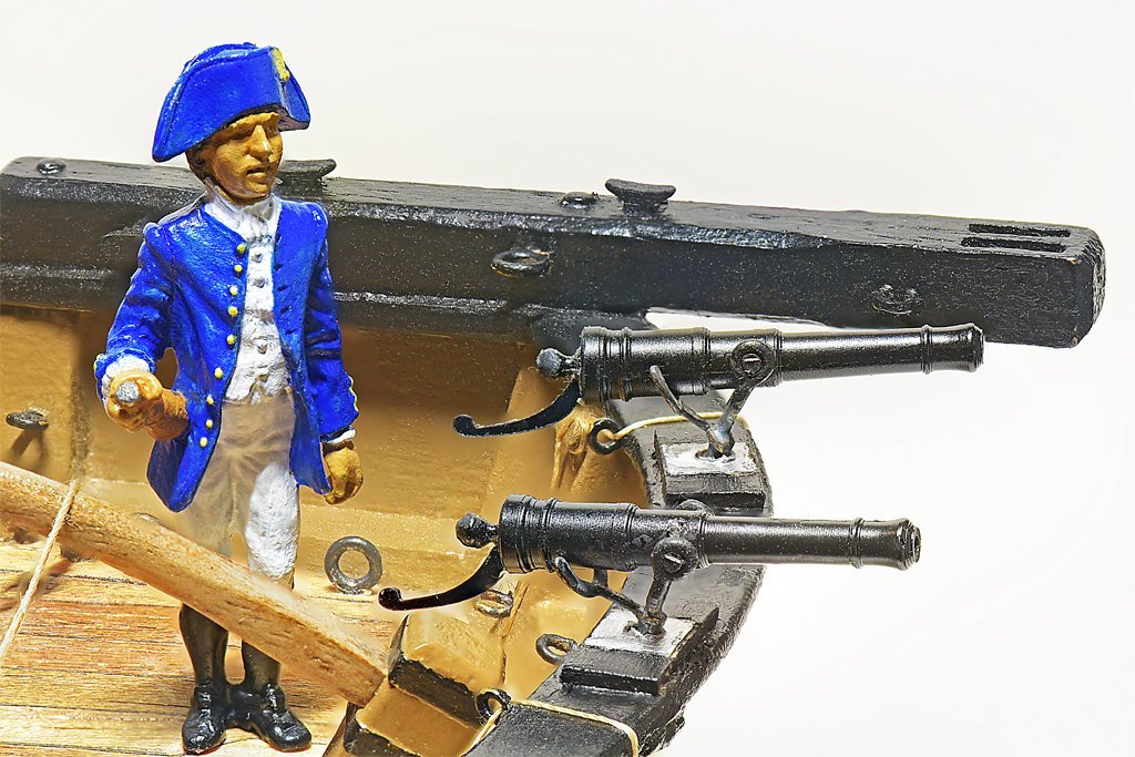
Another detail to be added before starting rigging was swivel guns. Some references say some early 1800s schooners carried them. So I thought I should add a few at the bow and stern. I ordered a package of "Resin Swivel Guns (13/16") w/handle and Yoke" from Syren Ship Model Company. The package included six molded resin guns with yokes and round plates for mounting them. It also included a handle for the back of the guns. However, you have to drill a hole in the rear end of the gun below the cascobel to mount the handle (not a problem). I looked in Chapelle's "The History of the American Sailing Navy" (1949) and on page 89 he has drawings of swivel guns just like the Syren product. Furthermore, the dimensions of the Syren guns are perfect for a 1:48 scale 1 1/2" bore 1/2 pound shot swivel gun like those used in the American Navy! The Syren mounting parts are OK, but I wanted to replicate something like the yoke on the swivel guns on the modern Lady Washington replica. These swivel guns look exactly like Chapelle's drawings and have the "U" shaped rest to hold the gun in position for loading. They also have a wooden handle attached to the rear end, and Chapelle says this was common, along with several other styles of handles. I thought about adding a wooden handle to the Syren parts, but I like the handles supplied with the guns and decided to use them. OK, how was I going to fashion the yoke and the "U" shaped fitting? Since I don't have a machine shop to make these pieces it would have to be pretty simple. I decided to use brass wire. The yoke was made from 0.025 inch (0.64 mm) wire as shown in the picture below left. After making the small loops for the gun's trunnions at each end of the wire I soldered the loops closed. Then the wire was folded double and the upper "U" shape bent to the proper width. Then the doubled part was soldered. These were cleaned up later with a file to remove excess solder. The "U" shaped rest was made from 0.012 inch (0.3 mm) brass wire as shown in the picture above right. The wire was bent around a 0.125 inch (3.2 mm) drill bit (the cannon is 0.115" (2.9 mm) where it fits into the rest). Then it was folded back double to finish the "U" and the support arm was created as shown. The wire ends of the rest piece were then wrapped around the shaft of the yoke and soldered in position. This was the only difficult part of the assembly. The two wire ends of the rest needed to wrap tightly around the shaft of the yoke, and the support arm of the rest should be aligned with the shaft of the yoke so the "U" was positioned correctly for the gun to fit into. But as I added solder to fasten the rest in place things wanted to move around. Eventually I worked out a way to keep everything in place while I soldered it. You can see how things fit to the gun on the right, but the rest arm should be a bit lower and horizontal, and the "U" bent up a bit to cradle the gun. After a while I had six yoke assemblies, six trunnion pins and the six guns. I drilled holes through the guns for the trunnion pins. The brass parts were blackened with Birchwood Casey Brass Black. After the guns were assembled I clipped off the excess length of the trunnion pins and touched up with a bit of flat black enamel. I decided to duplicate the arrangement on the Lady Washington and add thin wooden blocks to the rails where the guns would be mounted, and a thin metal plate for support. After these were glued in place and painted the swivel guns were installed.
- 421 replies
-
- 11
-

-

-
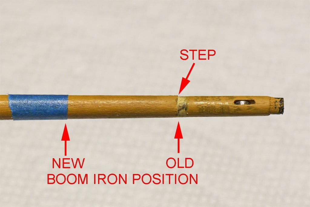
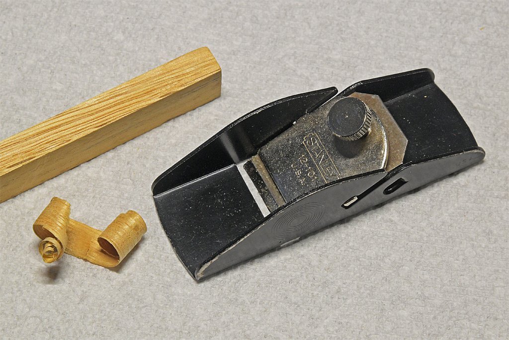
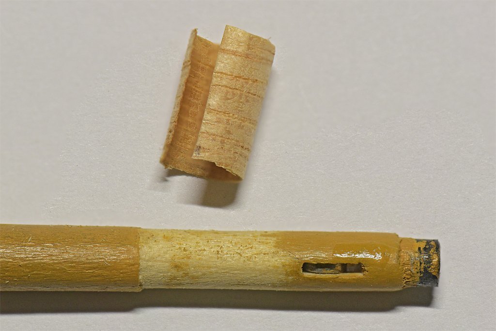
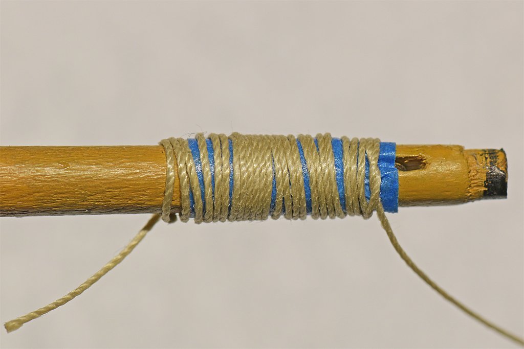
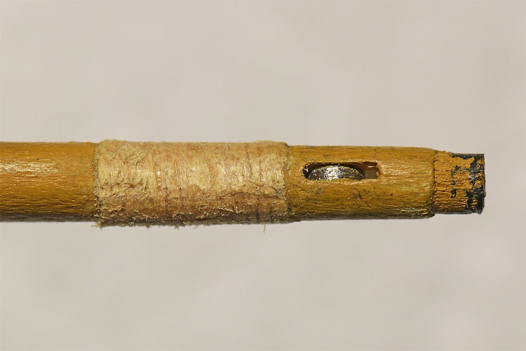
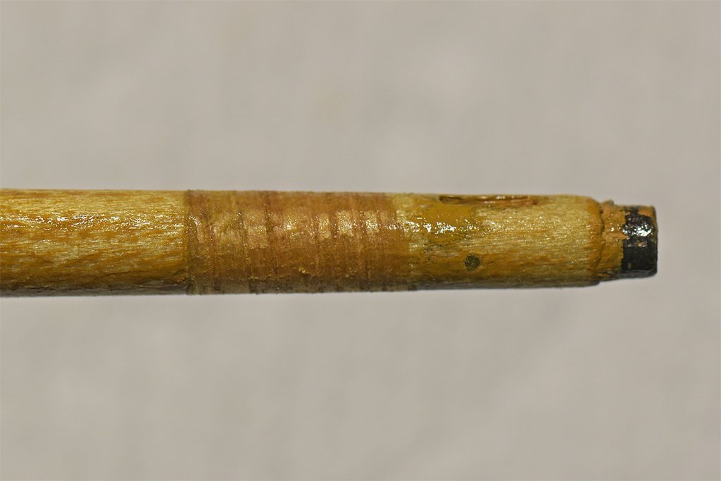
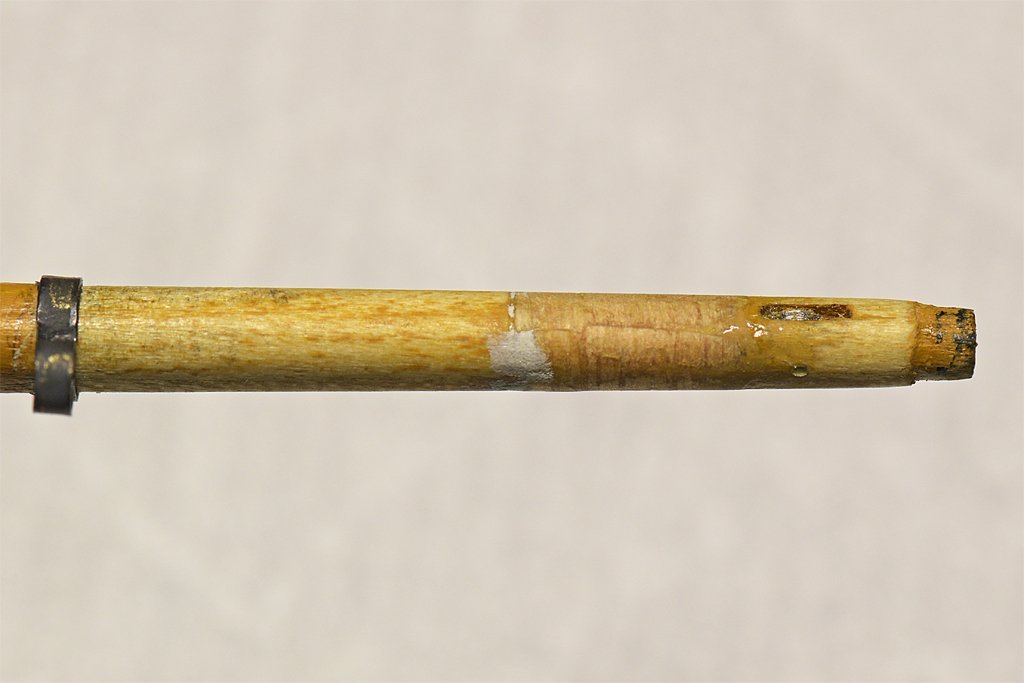
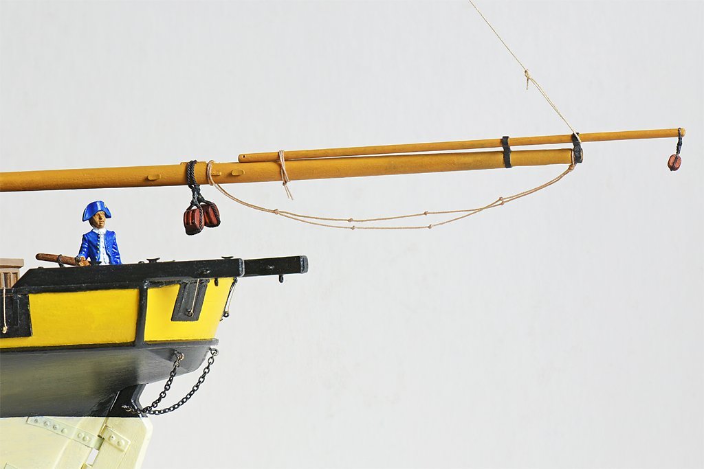
I had to fix the error in the ringtail boom iron position! I put the second boom iron about 1/5 of the boom length from the boom iron on the end of the boom, and the separation should be about 1/3 the boom length. I have several hours work in the existing boom, so I wanted to repair it if I could and reposition the forward boom iron. This photo shows where the original boom iron was positioned (old), and where it should have been placed (new). The original boom iron was a bit undersized so I filed a reduced diameter area where it was located. Some wood was also removed closer to the end of the boom so the iron would slip into position. Now I needed to build up the area (step) where the wood was removed. The solution (I hoped) would be to use my old Stanley miniature plane to shave a thin strip off a square dowel and use this as filler to be glued around the boom in the repair area. I had no idea if this would work but it seemed a better option that starting over on a new boom. The wood shaving was 0.009 inch (0.22 mm) thick. I wrapped it around the boom one turn, trimming the ends to overlap slightly. I used a liberal amount of Sig-Bond aliphatic resin to glue the shaving in place. I wrapped the shaving around the boom as tightly as possible - but of course the shaving wanted to spring back out. I wrapped some blue painter's masking tape around the shaving to hold the shaving tight around the boom. Then just to be sure I wrapped some carpet/button thread tightly around the tape to be sure the whole thing was compressed. After about eight hours I removed the tape and thread and started filing and sanding the wood shaving into shape. I forgot to take a photo before starting, so the picture on the right above is after a bit of reworking to shape the shaving. After sanding the shaving to shape it was coated with shellac (left). When that dried I used some Squadron White Putty to fill in some low spots (right) I also shaped the boom so the new boom iron could be added at the correct position. I should have used a more homogeneous wood for the shaving. The dowel I used had pronounced grain, and the softer light colored growth ring material sanded away faster than the darker growth rings. I sanded it carefully and with the shellac managed to get a fairly smooth surface. But this was another "learning experience." After two coats of paint, with sanding between the coats, the result looks pretty good. But just don't look too closely! There are some very slight "ripples" where the harder growth ring wood stands slightly proud. But all in all, I'll keep it. It is a lot better than starting over with a new boom! Two steps forward, one step back!
-
Note: I made an error in post #211 about the spacing of the ringtail boom irons. The spacing should be about 1/3 the ringtail boom's length, and not 1/4 to 1/6.
-
Roger, Thanks! Cook's 1773 folding anchor certainly predates Steve's revenue cutter. And clearly they came into use before the 1770s - at least for small anchors.
- 24 replies
-
- 3
-
-
- anchor handling
- schooner
- (and 1 more)
-
"I still think she is 21." Well, just remember, if there are a few new wrinkles they are a sign of improvement. My Admiral complains she is getting older, but I still think she is beautiful!
-
Kieth, I understand your concerns. When my elderly mother had cataract surgery I called her up that evening to see how she was doing. I'm OK" she said, but I could tell from the tone of her voice that something wasn't right. When I asked what was wrong she replied "I didn't know I had so many wrinkles!" But she could see a lot better.
-
Focus Stacking
Dr PR replied to Dennis P Finegan's topic in Photographing your work. How to do this.
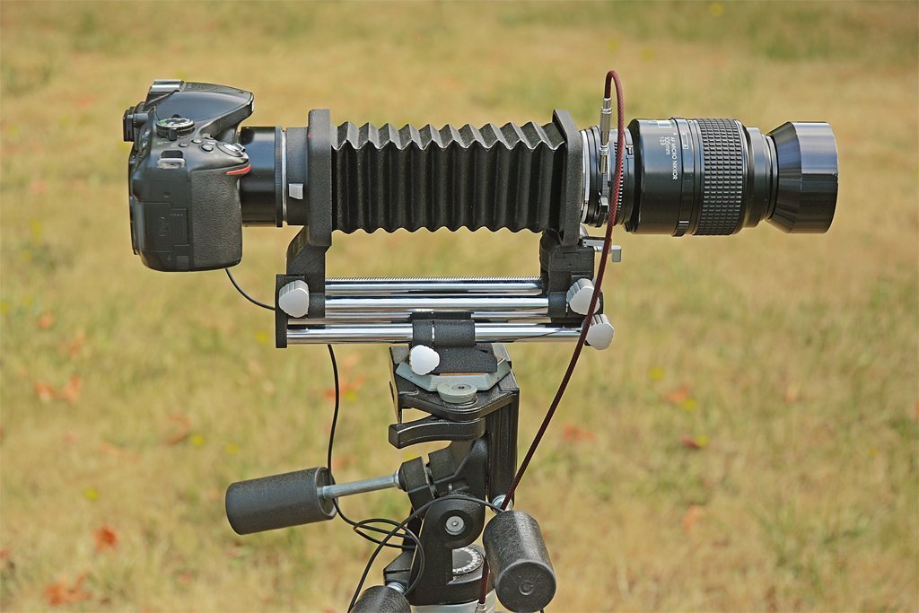
I got that dual rail "Bellows PB-4" decades ago (~1990) at a local camera store. I think it was out of production then, but someone found a bunch of unopened boxes in a warehouse in Portland, Oregon, and the local store bough a couple. I used it with a Nikon F3 and the old manual 105 mm macro lens (that lens is the reason I switched to the Nikon system). Fortunately the bellows was made way back in the manual film camera days (nothing automatic) so it just has the simple Nikon bayonet mounting ring. This is fortunate because that mounting ring doesn't interfere with all the electrical contacts inside the mounting ring on newer digital cameras. Of course there are no mechanical or electrical connections to the lens, and none in the bellows unit. So the lens has to be focused manually and the diaphragm has to be set manually before taking a photo. The diaphragm control ring between the lens and bellows allows the diaphragm to be controlled with the cable release. The diaphragm is normally open full to allow through the lens focusing. You just set the f-stop on the lens and when you push the cable release it closes the diaphragm to the setting. Be careful buying an older bellows unit (extension tubes or lenses) to work with modern cameras, because some of the older units have early electrical contacts that may damage the contacts in the latest digital cameras. I think Nikon doesn't make a bellows unit any more, but someone may. That old Nikon dual rail bellows unit has three gear driven moving sections. The base is a tripod mount, and this has a knob that runs on the loser rail pair to move the entire bellows unit back and forth on the tripod mount to move the whole bellows, lens and camera back and forth closer and farther from the subject. On the upper pair of rails are the two frames that support the ends of the bellows, the camera mount and the lens mount. Each of these has a knob to move them back and forth on the upper rails to allow the bellows to be opened and closed. All three movement knobs have locks to prevent the movement from moving. Lastly, the lens mount rotates around the vertical to provide the "tilt shift" feature for the lens that modeller_masa was talking about. This allows some pretty neat depth of field corrections for subjects with greater depth. I don't use it (or the old macro lens) much any more, but it is such an exquisitely machined, extremely high quality piece of equipment (Made in Japan) I can't bring myself to part with it! I love working with it so occasionally I will hunt for something really tiny to photograph with it. For the even smaller things I have a Leitz laboratory microscope with a Nikon camera body mount. Again, it is a very old film camera body mount that works with modern digital cameras because the simple bayonet mount doesn't interfere with all the electrical contacts in the camera body. And like the bellows, the microscope mount is top quality made in Japan (I purchased the microscope adapter in Japan in the early 1970s). It allows me to go down to 1000x magnification for bacteria and such - about the limit for optical resolution. -
It occurred to me that I should check the anchors that came with the Mantua Albatros kit to see if they are anywhere near the correct size for this model. Kit parts tend to be whatever was on the manufacturer's shelf and can be relatively random scale sizes. For the long convoluted saga of calculations of anchor sizes see this post: https://modelshipworld.com/topic/27410-small-ship-anchor-handling/?do=findComment&comment=1015834 Amazingly, the kit anchor with my 1980s Mantua Albatross kit has a shank length of 1.94 inches (49.3 mm)! I am building it at 1:48, with a beam of 19 feet (5.8 meters), so the kit anchors are just right!
-
Hey, isn't CA supposed to be able to fix anything? OK, so the anchors bit the dust. Now what? I have been looking for the formula for calculating the size of a ship's anchors. Most references say nothing more than that a ship had an anchor, and several more of several sizes. Occasionally an author does say how large an anchor is on a particular ship, but in totally obscure terms. For example, Roding says: "... the weight of large ships anchors is equal to the square of the ship's breadth ..." And he goes on to give an example: "The sheet anchor of a ship which has a breadth of 49 French ft and of which the weight is 7653 Livres ... for a ship of 20 feet breadth. 492:202 = 7653 Livres : x Livres = 1331 Livres." French feet (1.06 English feet), Livres (489 grams), Livres x Livres??? That's as clear as mud! Marquardt's The Global Schooner is the only reference I could find with meaningful dimensions for anchors, and that is not simple. In England in the 1800s the anchor weight is the ship's tonnage divided by 20 in cwt. CWT? 1 cwt = 50.8 kg = 112 pounds (today's weights). But that is only for ships, and if you have read many texts small vessels like schooners really are not ships and not worth mentioning. Marquardt does give this guidance for smaller vessels based upon a table by anchor manufacturer Young and Thompson at Sutherland, England (my calculations for anchor weight): Vessel weight tons Tonnage divided by Anchor weight English tons 5-15 10 0.5-1.5 25 12.5 2 40 13.33 3 60 17 3.5 100 19 5.26 >100 20 The AL model does appear to be based on the 1815 revenue cutter designs of William Doughty. But he designed vessels of 30, 51 and 80 tons, all with about the same deck layout and proportions. So which was it? Let's assume it was the 80 ton design (which is similar to the revenue cutter kitbash I am making). The 80 ton Dallas revenue cutter of 1816 was 69' 6" length and 19' 6" beam (Chapelle The History of American Sailing Ships, 1985, page 192, 194). So it would have an anchor between 3.5 to 5.26 tons. The average is 4.4 tons. But how large is that, and what scale was an old Artesiana Latina Dallas kit (if any)? Mondfeld's Historic Ship Models (1989, page 184) gives example of bower anchors (what the ship would have it if had only one or two, but some ships had three or four different size anchors) in cwt. CWT (hundred weight - C for 100 in Roman numerals) = 100 modern American pounds, but it was 112 English pounds in the 1800s. There are 20 cwt in a ton, both British and American. So a 4.4 ton anchor weighed 88 cwt. But Mondfeld says an 80 cwt bower anchor is what a 100-110 gun ship of the line would carry, and schooners were just a fraction of that size! PUNT! This is typical of the quagmire I run into every time I try to figure out any dimensions for historic ships! Any two authors rarely agree on anything, and each uses his own calculations and speaks his own language (with no glossary)! Nothing is simple!!! **** Let's try again. Marquardt says a schooner's anchor dimensions are: shank length = 4/10 of a ship's breadth shank width = 1/27 to 1/24 shank length So with the 80 ton Dallas' beam of 19' 6" (234 inches) the shank length would be 93.6 inches or 7.8 feet (2377 mm). At 1:48 scale that would be an anchor with a shank 1.95 inches (49.5 mm). Amazingly, the kit anchor with my 1980s Mantua Albatross kit has a shank length of 1.94 inches (49.3 mm)! Mantua has sold it as 1:40 scale but I am building it at 1:48, with a beam of 19 feet (5.8 meters), so the kit anchors are just right!
- 24 replies
-
- 2
-
-
- anchor handling
- schooner
- (and 1 more)
-
Roger, Good point! Kit anchors are rarely to scale - they are just what the manufacturer has on hand in an approximate size. Also, Steve's Dallas kit anchor is an iron shank type where the iron stock can be slipped through the hole in the shank and folded beside the shank. When did this type of anchor come into use? Mondfeld's Historic Ship Models (page 186) shows the Admiralty pattern from 1840 and Trotman's anchor from 1850. I looked in other references and could find no earlier references for this type anchor. The small revenue cutters were built early in the 1800s, probably before this type anchor was introduced. For small vessels the anchor was probably stowed on deck lashed to bitts or timberheads.
- 24 replies
-
- 1
-
-
- anchor handling
- schooner
- (and 1 more)
-
Focus Stacking
Dr PR replied to Dennis P Finegan's topic in Photographing your work. How to do this.
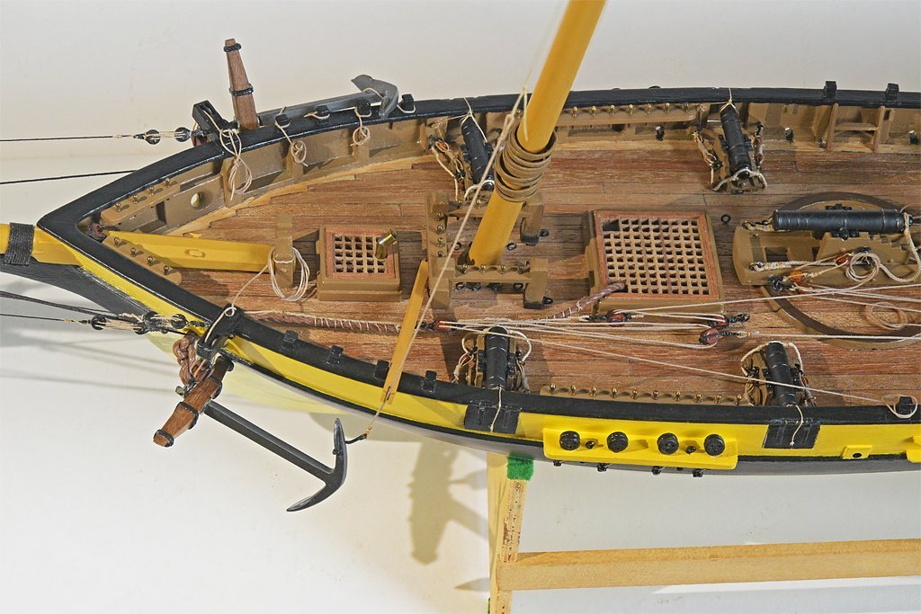
BB, You are quite correct. Sorry I misunderstood you. I do use a rail for what I would call extreme macro photography. This is a Nikon two rail bellows unit. It is very sturdy. The older manual 105 mm macro lens is attached to the front of the bellows unit and the camera body is attached to the rear - using an extension tube here because the hand hold projection on the digital camera body would otherwise contact the bellows unit frame (the modern digital camera body and ancient film camera bellows unit weren't designed to work together). Because there is no communication between the camera and lens a manual diaphragm control (between bellows frame and lens) and cable are necessary. The lens diaphragm is adjusted manually. The camera body is set to Manual mode (which I always use anyway). This assembly allows the compensating focus/ frame control you are talking about. But the primary use for the bellows is high magnification macro photography. As shown here it allows the distance between the camera and lens to be varied. The greater the distance the higher the magnification. The macro lens produces a 1:1 scale (life size) image on the photo element (most lenses create approximately 1:4 scale images, or 1/4 life size). This is called the reproduction ratio. With the bellows fully extended I have produced 5:1 scale images (5 times life size) on the photo element. It is useful for very tiny flowers (1/8 inch or 3 mm and smaller). However, such large magnifications aren't necessary for photographing ship models where the life size object is many times larger than the photo element. For whole model pictures I use a f 2.8 16 to 80 mm zoom lens (0.25 x reproduction ratio) that will focus to about 14 inches (350 mm) from the film plane (about 9 inches or 229 mm from the end of the lens). For smaller parts of the model I just use the newer automatic 105 mm macro lens (1:1 reproduction ratio) that will focus to 12 inches (314 mm) from the film plane (about 5.75 inches or 146 mm) in front of the lens). In both cases I just mount the camera on a sturdy tripod and adjust the focal point with the lens without moving the camera body. This is a lot easier and simpler than messing with the rails. The picture in my post above looking down the deck of the model was made this way.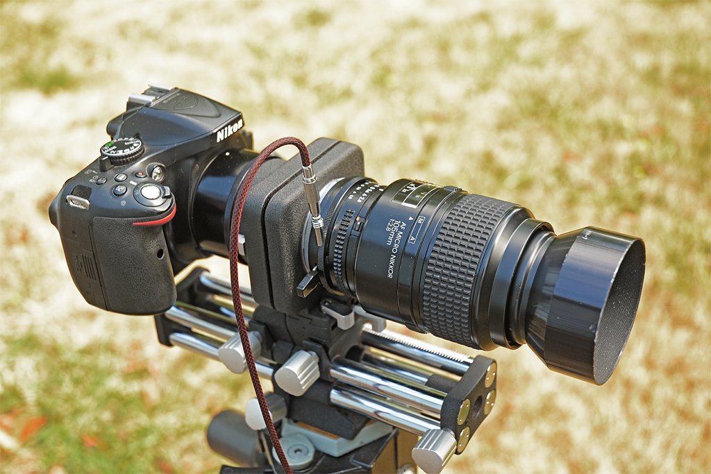
-
I agree. We were told to not lean on the life lines (chains between stanchions). Life rails (pipes) were likewise not to be trusted. Both served to mark the edges of decks at night and provide something to hang on to when the deck was pitching and rolling. In the case of the revenue cutter model the stanchions appear to be oversized and probably strong enough to support the anchor under "normal" conditions. But I doubt that the anchor was attached to the real stanchions on these small vessels if they were going into any rough seas or high winds.
- 24 replies
-
- 1
-
-
- anchor handling
- schooner
- (and 1 more)
-
Focus Stacking
Dr PR replied to Dennis P Finegan's topic in Photographing your work. How to do this.
That might work iff the camera was mounted on a rail and could be moved in a perfectly straight line to and from the desired image center. However, I can't see any advantage to doing that over just keeping the camera in a fixed position and changing the focus point of the lens. If you change the distance of the camera to the object being focused the image of the object will change size in the images relative to other objects. Also, the relative angles from the focal plane to objects will change. Either effect will cause problems with focus stacking. Any slight side to side or up and down motion (camera or object) will play havoc with the stacking software - I speak from lots of experience shooting photos of wildflowers where wind can change the relative position of the flower in successive photos. It changes the view angle, so objects that are hidden by closer objects in one photo will be "unhidden" in subsequent photos. Even if these things are out of focus they will appear in the photo because there is no matching in focus image in other pictures. If the camera moves all bets are off what the software will do, but most often artifact I see are multiple images side by side of the same object. If this problem isn't too bad it can be corrected by editing the picture. But you really have to want the photo to spend that much time on it! Here is a recent focus stacked image made from twelve pictures. The camera was fixed on a tripod and the lens was focused successively from the closest object to the more distant. Each image was 6000x4000 pixels, but successive photos captured slightly larger or smaller areas of the model due to changing the distance to the focus point. The images were first aligned, which stretches "smaller" images or shrinks "larger" images so the images of individual objects are the same size in all photos. Then the images were stacked. The image was slightly cropped to remove the blurry edges that result when one image area is larger than another and there are no matching in focus objects in the surrounding part of the larger images. The main problem I see is a result of the way the software decides what is in focus and what is not. An example is the prominent vertical fish tackle rope in the foreground. It is in focus in closer images, but the edge of the deck house in the background was out of focus in those images. The deck house was sharply focused in the distant images where the fish tackle was out of focus. When the images were stacked the deck house edge was out of focus for a short distance on either side of the rope. The software chose the blurry edges near the rope instead of the sharp edges of the deck house. I cleaned this up by editing the image. If the camera had moved vertically or horizontally (or both) there would be multiple edges for every object running from near to far in the picture. It would be a real mass to try to clean up with editing.
-
Jim, I have that book and I am sure that is where I saw the mechanisms for releasing the stopper to drop the anchor. However, I suspect that mechanism came into use in the later part of the 1800s or early 1900s. Most of the books I have read about late 1700s and early 1800s ships just say the loose end of the stopper was "secured to a cleat." But if the weight of the anchor was pulling on the stopper it would not have been easy to get the rope off of the cleat! I think I have seen a sketch of a stopper with an eye spliced into the loose end, and the eye was hooked over a pin on the bulwark or cathead. To drop the anchor the pin was pulled out. However, I have no idea where (or if) I saw that.
- 24 replies
-
- 1
-
-
- anchor handling
- schooner
- (and 1 more)
-
Steve, I think that would not work in heavy seas or when the ship heeled over in strong winds. The anchor can rotate around the single attachment point and could easily fall overboard. The ring at the top of the anchor could be secured to the first stanchion and the junction of the shank and arms (crown at the bottom) lashed to the second stanchion. These small revenue cutters were designed to operate close to shore and didn't spend a lot of time out at sea. If a storm came up they would head back into harbor. Still, it would be bad if the anchor slipped over the side when you weren't expecting it, so securing it with two ropes (the stopper on the ring and shank painter on the crown) would be cheap insurance. If the vessel was just going out on a short one day mission they would have left the anchor cable secured to the anchor. But I have seen several references that said the anchors on some schooners were hauled back and stowed below the main hatch. Probably on ocean-going vessels that would be at sea for many days. Because the ship doesn't have catheads the anchor would be raised and lowered with the fore mast tackle - the strong cargo handling tackle.
- 24 replies
-
- 1
-
-
- anchor handling
- schooner
- (and 1 more)
-
George, Lees describes the method I have shown for the main anchors, but he also says the other anchors were brought in with the mast tackle. Lever describes several ways to haul in an anchor, including hooking the fish tackle to the block on the mast tackle. Maybe I did take liberty calling the short rope a "messenger" but I didn't know what else to call it. It serves the same function as a messenger. The term messenger usually refers to a rope loop that runs around a capstan and through a block on the bow. The anchor cable is attached to it with nippers or a jigger (Lever page 109). Druxy, I have seen it depicted several ways. I think it was Chapelle who said the fish hook was first hooked to the anchor ring when it broke the surface and the mast tackle was used to lift the anchor ring up to the cat stopper. But I think this was on vessels (fishing schooners) that had a cathead but no cat tackle. Then the fish hook was taken from the anchor ring and hooked around something at the crown end to raise the crown. Lees (Masting and Rigging English Ships of War, page 128) shows it hooked to the flukes. Chapelle (The American Fishing Schooner, page 321 Anchor Gear (notes)) says the hook was used to catch an anchor fluke. A problem with just getting the hook around the shank of the anchor when it is hanging vertically under the cathead is that the hook can slide along the entire length of the shank to the top. They needed to get the hook around an arm in order to raise the lower part of the anchor (crown) up so the shank was more or less horizontal. If the hook was around an arm it would slide up until it caught on the fluke. At least that is the way I imagine it. I find these discussions about how things were (might have been) done to be as interesting as building the model itself. It took me 14 years to create my CAD model of the USS Oklahoma City CLG-5 because most of that time was spent digging up tech manuals, data sheets, blueprints, etc., and discussing things with other sailors who served on the ship. I have been working on the Albatross deck fittings for four years this month! Good thing I am not in a hurry. Or as I saw on a postcard back in the '70s: Maybe it is a good thing I am moving slowly because I might be going in the wrong direction! John, Thanks! As I have said many times, there is a lot of guesswork in figuring out how things were done centuries ago. Back then there were a lot of details that weren't written down because everyone already knew them!
-
Henry, I too have read something about a quick release for the anchor stopper for dropping the anchor. And I cannot remember where either!
- 24 replies
-
- 1
-
-
- anchor handling
- schooner
- (and 1 more)
-
See this link for a model implementation of this anchor retrieval method: https://modelshipworld.com/topic/19611-albatros-by-dr-pr-mantua-scale-148-revenue-cutter-kitbash-about-1815/?do=findComment&comment=1015509
- 24 replies
-
- 1
-
-
- anchor handling
- schooner
- (and 1 more)
-
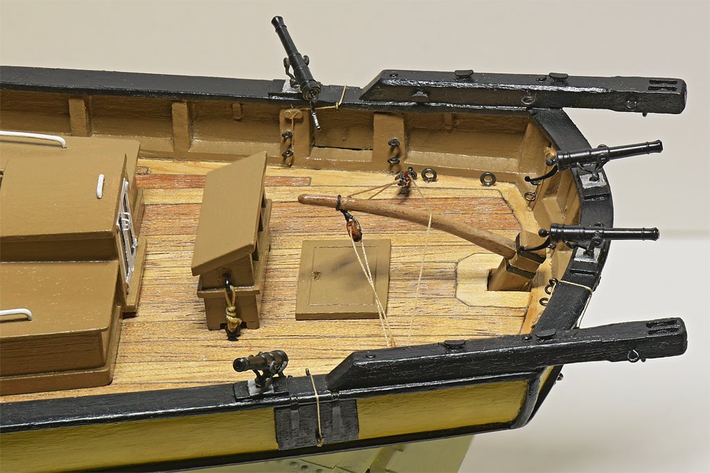
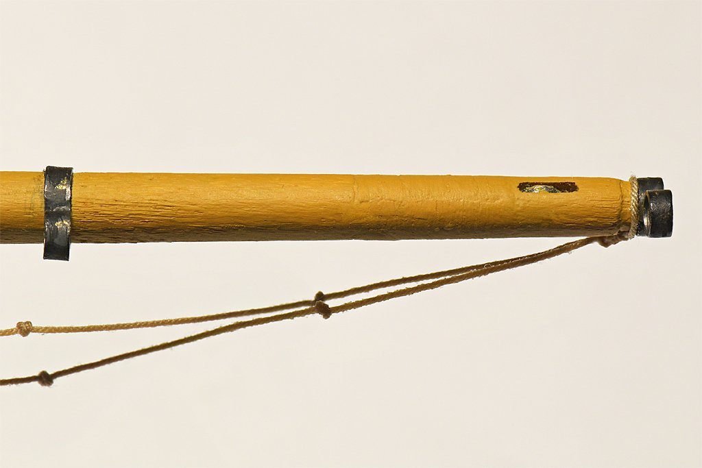
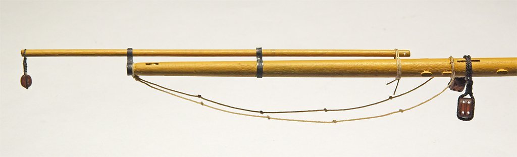
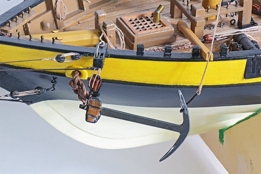
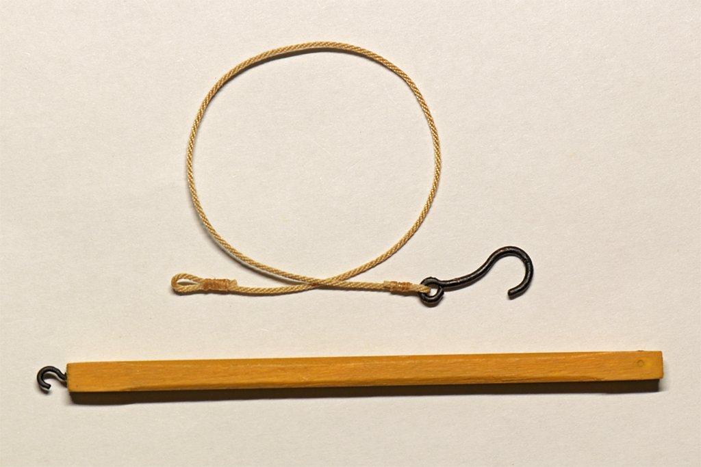
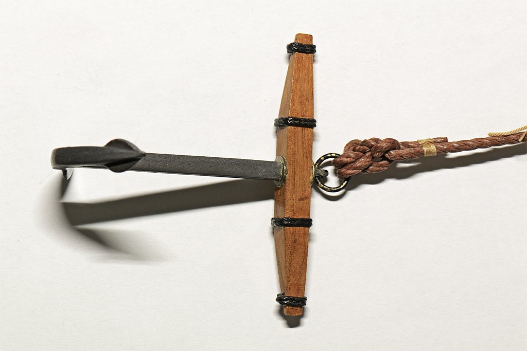
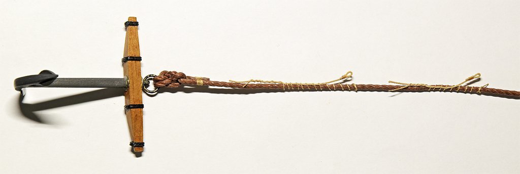
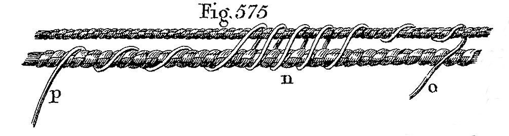
And now for something entirely different ... Some time back there was a discussion on the Forum about anchor handling on small ships that did not have a capstan or windless. https://modelshipworld.com/topic/27410-small-ship-anchor-handling/?do=findComment&comment=787942 You don't see fishing the anchor depicted on many models (bringing the anchor up to the rail when retrieving it is called "fishing" the anchor), so I decided to try to implement the strategy on this model. Remember that some of this is speculative, but it does follow what several references say was done. First there is the anchor itself. I assembled this piece back in the 1980s when I started this build. The metal part appears to be a lead casting, and it had prominent mold seams. I filed it down to eliminate the seams, and it was shiny lead color. Now 35 years later it has developed a nice dull metallic look. The stock and ring are what came with the kit. The anchor cable is attached to the ring with a fisherman's bend which Marquardt says was used with smaller anchors. While this one was relatively large, a vessel this size would have a "smaller" anchor. Whether the fisherman's bend was correct for this one I am not sure, but that's what I used. The next part of this anchor retrieval method was the "nipper." Lever says the anchor cable was lashed to a messenger cable with nippers. The picture shows how this was done - the nipper is the small line that loops around both messenger and cable. The messenger is the part that was actually hauled upon, pulling the larger anchor cable with it to lift the anchor. On ships with capstans or winches the messenger was pulled by these. But when a vessel had neither a tackle was used to pull the messenger. In this case the messenger was just a short piece of rope with an eye spliced in one end for the hook of a block to fasten to. For this job I used my "Quad Hands" mechanism. I bought this a year or two ago after seeing one in another post on the Forum. It looked like it would come in handy when there were a lot of loose ends to manage. I have been using a simple two arm unit mostly, but here I had to pull the anchor cable taut while wrapping the nipper line around the cable first, then the cable and messenger, and finally the messenger only (six ends). I keep a bottle cap with a drop of white glue handy, and occasionally apply a small drop of glue on the windings with a needle point to prevent everything from unwinding. And the tweezers are essential tools for this kind of work. Here is the anchor and cable with two messengers and nippers in place. The next part of the puzzle is the fish boom and fish tackle. The boom is a small portable pole with a sheave in the outboard end and a hook on the inboard end. The hook catches an eye bolt in the deck to secure that end. The fish tackle runs over the sheave. The fish tackle is a rope with the fish hook spliced into one end and an eye in the other. The real thing would have a thimble in the eye, but fashioning a 0.020 inch (0.5 mm) thimble is just a bit too much of a challenge (I used white glue to stiffen it). Here you see the fish tackle in use. The hook catches on the flukes of the anchor while it is hanging from the anchor cable. The eye on the fish tackle is hooked onto the fore tackle. This heavy lifting cargo rig is used to raise the anchor. The fish boom guides the crown end of the anchor outboard of the hull. Here the head of the anchor has been "catted" up to the cathead with the cat tackle, but the tackle is still attached. After the anchor is hauled up a stopper rope or chain (not shown) is looped through the anchor ring to support the head end and the cat tackle is unhooked from the ring. In this model two retrieving or in-haul tackles made of double sheave blocks are used to haul on the messengers. One is hooked to a ring bolt just aft of the hatch (normally used to rotate the pivot gun). It has been drawn back to pull the nipper almost to the hatch. The second tackle hooks to a runner line with an eye in one end and a hook on the other that is attached to another ring bolt in the deck (or any other secure hold). The second tackle is run out to the forward messenger. While it is being hauled in the first tackle will be unhooked and run out again, and the messenger will be untied from the cable and moved forward again to receive the first tackle, and so on. Here is a view from the bow showing all of the parts of this anchor retrieval rig. Note that the falls for the cat tackle and retrieval tackles are secured to whatever stout attachments that are handy. This is a temporary setup so the ropes are not belayed in a more secure fashion. Since the anchor is hanging from the cat tackle the strain is relieved from the in-haul tackle. A "shank painter" rope or chain would be looped around the crown of the anchor and secured to timber heads or cleats on the bulwark. Then the fish tackle would be unhooked and it and the fish boom would be stowed. The stopper would be attached to the anchor ring to take the weight of the anchor head and the cat tackle would be unhooked. The anchor was stowed to the rail as shown in earlier photos of the starboard side anchor. https://modelshipworld.com/topic/19611-albatros-by-dr-pr-mantua-scale-148-revenue-cutter-kitbash-about-1815/?do=findComment&comment=1011922 Normally on long voyages the anchor cable would be detached from the anchor and the cable would be stowed in the cable tier below the main hatch. All of the parts shown here are documented in period publications like Darcy Lever's "The Young Sea Officer's Sheet Anchor" (1808). Marquardt's "The Global Schooner" shows similar rigs for schooners. But the places I have shown the retrieval tackle and falls to be belayed is just speculation. I think this may be the last "deck work" that has to be done before starting the rigging of the mast and sails. But I still need to build the ship's boat and hang it from the davits on the stern. That is a separate modelling project in itself!
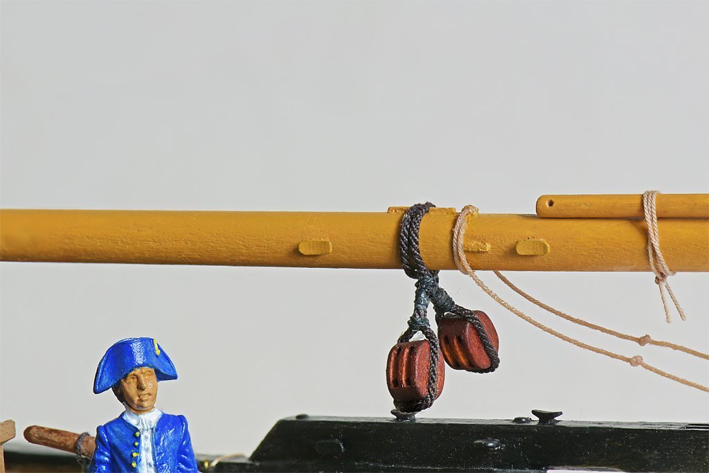
-
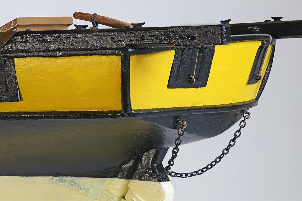
I have a little more progress to report. I have been checking for "last minute" details to finish before I dive into rigging the masts. Every time I check again I find some other small detail that will be easier to install before the masts are rigged. If you have been modeling long you will appreciate the messy details. First I installed the boom sheet tackle blocks on the boom. Each block is stropped and secured to the boom separately. No problems here. Then I installed the foot ropes (also called "horses" in some books) on the outboard end of the boom. It was a simple task, but I had problems getting the knots on the two ropes to line up closely. One knot was a bit out of position, and I needed a needle to open it so I could move it. I went to the cabinet to get my sewing kit, and it wasn't there. After searching the house for the misplaced kit for thirty minutes, I found it where I left it after getting a spool of thread to use on the model! All I wanted to do was finish a simple modeling task and it turned into an annoying delay! Here is a photo showing how the thumb cleats on the boom are used. The two on top hold the boom sheet tackle in place. The two on the sides secure the inboard end of the foot ropes. The books show these foot ropes but don't say much about them. This is how these ropes are rigged on the Lady Washington. I am assuming (unjustifiably) not much has changed in the last two centuries to justify this configuration. This picture also shows the temporary lashing to hold the end of the ringtail boom in place when the sail isn't rigged. I don't plan to fly the sail on the model. I am still fiddling with the foot ropes to try to get them to hang "naturally." Another last minute detail was the rudder pendant chains. The books don't say what size chains were used, but from the drawings in the books and photos of the Lady Washington I guessed that the width of the links was 1/3 to 1/4 as wide as the rudder. I picked what looked like a piece of brass chain from my parts stash, cut it to length and blackened it. It did blacken nicely. Trying to make shackles 0.050" (1.27 mm) wide would be a bit too tedious work, so I decided to just open the links at the end of the chains, hook them over the ring bolts on the rudder and transom, and close them again. “The best laid schemes o' mice an' men / Gang aft a-gley.” Robert Burns Things started going a-gley almost immediately. The chain must be brass plated iron, because every time I tried to pick up an end link the chain leapt up and stuck to the (magnetized) tweezers! I tried and tried again but I just couldn't pick up the open links without getting other links that were always (of course) in the way! Frustration was building. Most of the metal work on the model is with brass, so the magnetism the tools picked up over the years had gone unnoticed. Now they had to be demagnetized. I tried a little Husky brand "Magnetize/Demagnetize" tool that had been around for years. It was worthless. I think the "demagnetizer" just magnetized things worse. Than I remembered I have an old 120 VAC soldering gun with large induction coils. I turned it on, brought the tools close and they vibrated in the alternating magnetic field. I moved them back and forth a few times, then pulled them away slowly before releasing the trigger to turn it off. Voila! It worked perfectly and the tools were demagnetized. Even so, those links are tiny, and they have a way of turning the wrong way, slipping off the chain, refusing to go over the ring bolts, and so on. Murphy was right! It must have taken an hour to secure the four ends of the chains to the ring bolts! I write this in case there are any new modelers reading this thread. This was just a normal modeling day! Burns and Murphy must have been ship modelers!
-
The same phenomenon is useful (to a degree) when moored on the starboard side and leaving a berth. You want the stern to swing to the port (bow to starboard) because typically there is another vessel moored behind that you must avoid. However, on the little single screw minesweeper I was on the spring lines played a far greater role in swinging the stern out than the rudder or propeller rotation. But these arguments apply only to single screw ships. With twin (or quad) screws you can run one side forward and the other astern to "twist ship" more or less however you wish. On the cruiser (four screws) we always preferred docking starboard side to the pier. But my experience has been that you only have a choice of berth that the harbor master assigns, and you may have to dock on either side.
-
John, I did the same "last minute" review of deck fittings and belaying points prior to starting rigging - and like you I found a bunch of things I overlooked! And I found an error in my belaying plan that just happened to use the last two unused belaying pins on the fore mast fife rail. Still, I'm pretty sure I will discover yet another missing belaying point before I am done! I have had spotty results with Brass Black also. I wash with soapy (dish soap) water and rinse after soldering to remove water soluble flux. Then I wash with acetone to remove any resin flux, oils, etc. After that I clean/etch with white vinegar (dilute acetic acid) for a while, then wash again to remove the vinegar. Still I have had spots that just didn't blacken. However, a good scrubbing with the wire brush seems to improve the blackening. I suspect the irregular results may be varying hardness due to annealing the brass while working it and heating with soldering. This might cause the different parts of the metal to react at different rates to the Brass Black. Brushing cleans oxides off and removes excess solder and whatever else is on the metal surface, and it gives the surface a but of "tooth." I also use flat black enamel paint to touch up spots (Model Master Flat Black FS37038).
- 282 replies
-
- 2
-
-
- Bluenose
- Model Shipways
- (and 1 more)
-
Horseshoe Plates
Dr PR replied to tmj's topic in Building, Framing, Planking and plating a ships hull and deck
When did these horseshoe plates come into use?

