
HOLIDAY DONATION DRIVE - SUPPORT MSW - DO YOUR PART TO KEEP THIS GREAT FORUM GOING! (89 donations so far out of 49,000 members - C'mon guys!)
×


Dr PR
-
Posts
2,445 -
Joined
-
Last visited
Content Type
Profiles
Forums
Gallery
Events
Everything posted by Dr PR
-
 John, Jack and Chris, Thanks for your comments. Keep in mind that this is 1) a "theoretical" version of a revenue cutter, and 2) that I have discovered several errors in my work - all part of the learning experience. In fact, I am enjoying the learning more than the building.
 -
Jack, When turning the pivot table you would only pull on one or two of the corners to turn it, and maybe push on the other two. Seems to me that if you had four tackles two would always be in the way and getting tangled up. Another thing to remember is that things happened much more slowly two centuries ago. A tall ship with sails aloft would be visible for 10-15 miles from the deck of another ship, or more from the mast top. Those ships moved at 6-8 knots max, so even if the two ships were sailing directly at each other at their best speed it would be an hour or two before they closed enough to duke it out with the short range cannons of the day. It wasn't necessary to be able to run out the guns and rotate the pivot gun quickly. There was plenty of time to load the guns and set the sails to maneuver for the best advantage. Today you get only a minute or less warning when a wave skimming supersonic missile pops up over the horizon. Reaction time has to be just a few seconds instead of hours!
-
Would you buy pre-owned wooden kits?
Dr PR replied to Frank Burroughs's topic in Wood ship model kits
Frank, There is NO comparison between plastic model kits and wooden model kits. None! They are entirely different worlds! As a kid I built dozens of plastic models (I actually stared with balsa wood kits before plastic models were invented). The pieces fit together nicely, and all I needed was a bit of glue and some paint, with a minimum of tools. But in middle/high school I started building my first scratch build vessels (a schooner and a Chris Craft cabin cruiser) with whatever materials I could scrounge up and no plans - just what I could draw up from my imagination. They weren't much to look at, and certainly weren't accurate, but I learned a lot! Then, after college (1970s) when I could afford it, I started building wooden ship model kits. I quickly learned that wooden kits are much closer to scratch building than plastic kits. The parts never fit together without some reworking and I always had to create many of the details from scratch. And they really weren't very accurate replicas of the real things. I have newer (1990s) wooden ship kits in my stash but they aren't much better. The "instructions" often were just one or two pages saying "build the hull, add the masts., and finish the rigging." Newer kits with laser cut parts and an extensive collection of fittings are closer to the plastic models of fifty years ago, and some actually have credible instructions. But they still are much harder to build, especially for a newbie! Just look at some of the kit builds on the forum by novice wood ship modelers. Often parts do not fit correctly or the modeler just doesn't understand the arcane terminology in the instructions. The hassles of new wooden kit builders speaks much more loudly than all the pretty advertising BS put out by the model companies!! Don't let this discourage you. Just realize that your first wooden ship model, no matter what the kit manufacturer is, will not be a museum quality piece. It will be a challenge! You will need a lot greater variety of tools and much more experience than for your last plastic model build. But it will be your first step toward that future museum piece (family heirloom). And the satisfaction of having overcome the difficulties and finishing even a basic wooden ship model makes it worth the effort! -
Hull and Deck treenails
Dr PR replied to Loracs's topic in Building, Framing, Planking and plating a ships hull and deck
I think maybe Jaeger is not a fan of treenails (trunnels). The things he says are correct, except perhaps the visibility of the wooden plugs. I served on three ships with wooden decks, and if you looked closely while walking the deck you could just make out where the plugs were (I had exceptional eyesight back then). And I have seen photos of HMS Victory where the trunnels in the deck are visible. But, as he says, every effort was made to hide them on the real ships. If your goal is to make a realistic looking model from a normal (or close) viewing distance, forget the trunnels. But if you are making a cutaway model intended to show how the vessel was built you may want to include trunnels, and take steps to be sure they are visible. -
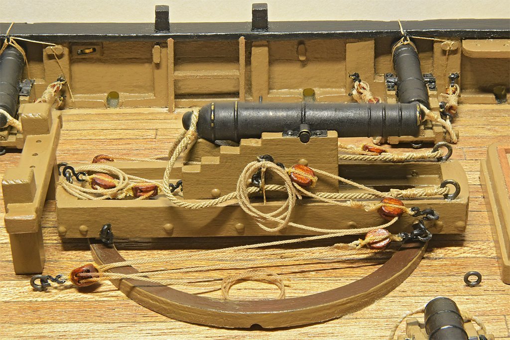
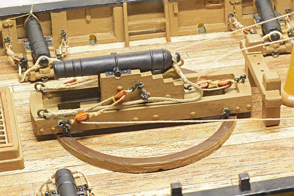
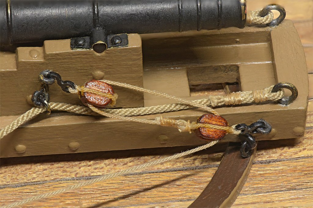
I have completed the pivot gun rigging. I decided to loop the gun tackle falls on the sides of the carriage. I have seen drawings and photos of this configuration. I added the pivot table tackle - a luff tackle configuration, and just looped the falls on the deck inside the circular rail. For this I have started adding the ring bolts to the deck. There will be a couple dozen more for the standing and running rigging. Some builds show four sets of tackle for the pivot table - one on each corner - but a bit of thought will tell you only two are necessary. They are shown in a stowage position with the gun aligned on the center line. They can be unhooked and reconnected to any of six ring bolts arranged around the gun to position it at any angle. I will unhook the pivot table tackle and remove the gun assembly (and all other deck furniture) while I am working on painting the hull bottom. I found another problem with using the alcohol based leather dye on the blocks - a very bad idea! On the lower left double block of the pivot table tackle you can see where I brushed on some shellac to stiffen the rope. The dye in the block wicked up the rope, leaving a nasty brown stain. This has been a learning experience! I should have used the white glue instead of shellac. Better still, I should have painted the blocks!
-
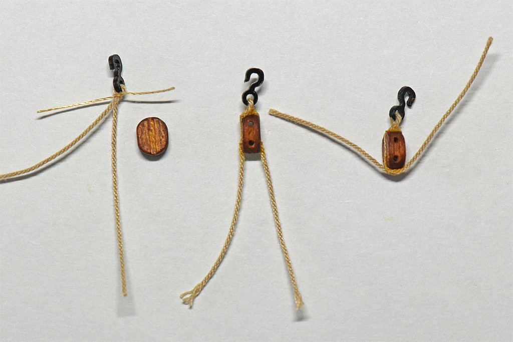
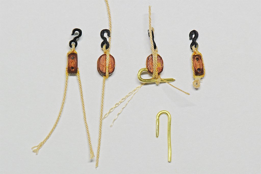
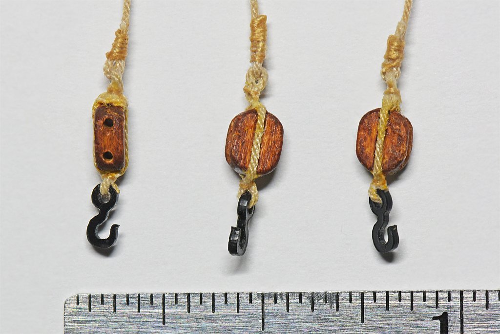
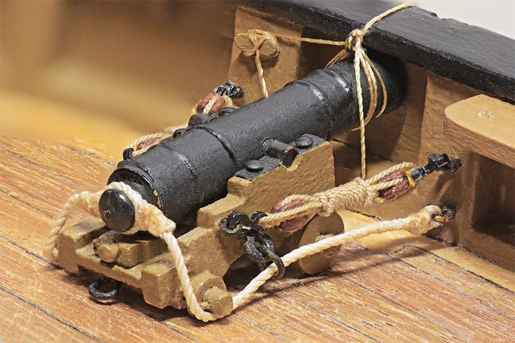
I have been working on the pivot gun tackle. It is a 12 pounder, so the blocks and rope are larger and easier to handle than for the 6 pound carriage guns. The blocks are 5/32 inch (4 mm) and the rope is 0.018 inch (0.45 mm). The hooks are 4 mm. The breech line is 0.035 inch (0.88 mm). The method for rigging the blocks was pretty much the same as for the 3/16 inch blocks used on the carriage guns. First I ran a short piece of the rope through the eye of the hook and then tied a knot of small stuff (0.0025 inch/0.6 mm silk thread) around the rope as seizing. A small amount of white glue (school glue or PVA) was added to the knot and allowed to dry. Then the excess small stuff was cut off. Then glue was applied to the sides and end of the block and the rope was pulled tight around the block. After the glue set a drop of glue was added to the other end of the block and the rope strands were folded over. After the glue dried the excess rope ends were cut off. The procedure was similar for blocks with an eye opposite the hook for the standing end of tackle to attach to. After the rope ends had been glued to the sides of the block, one end was folded over the end and glued. After the glue dried the excess was cut off. The other end remained straight. A "U" shaped brass wire tool was inserted in a hole in the block (see picture). The remaining rope end was looped around the longer end of the wire and back across the end of the block. The loop was then secured with a knot of small stuff. A drop of glue was placed on the knot and on the end of the block to hold the rope end. After the glue set the tool was removed and the loose ends were trimmed off. The standing end of the tackle rope was looped through the eye on a block and secured with a knot of small stuff. Then one end of the small stuff was wound around the rope and tied off again to form the seizing. The seizing was covered with white glue and allowed to dry. Edit: I think it isn't necessary to tie the eye on the end opposite the hook. You can just use a pin to create an opening between the block and the strap. Then you can run the standing end of the tackle between the block and the strap and create an eye in the standing part. Here is a photo of the pivot gun tackle and another of the entire pivot gun. The falls remain loose because I haven't decided how I will secure them. I prepared the breech rope cut splice for the cannon cascobel as described earlier in post #59: https://modelshipworld.com/topic/19611-albatros-by-dr-pr-mantua-scale-148-revenue-cutter-kitbash-about-1815/?do=findComment&comment=650378 The other ends of the breech rope were secured to ring bolts in the pivot slide with double seizings. I will rig the tackle for the pivot gun turntable similar to the gun tackle after I have painted the bottom of the hull (I don't want the gun sitting high on the deck while I am working with the hull inverted). I think I will use a luff tackle (single and double blocks) instead of a gun tackle (two single blocks) because it would take a lot more force to drag the turntable around than to just move the gun on the slide. Here is a photo of the (almost) completed guns.
- 421 replies
-
- 10
-

-

-
first time rigging - tools and books suggestions
Dr PR replied to Frank Burroughs's topic in Masting, rigging and sails
Frank, CAUTION! You are creeping into the rabbit hole! There are a lot of books on rigging! Here are a few I have found very useful: 1. Underhill's Masting and Rigging the Clipper Ship and Oceanic Carrier (Brown, Son & Ferguson, Glasgow, Scotland, 1972). It is an excellent book with a tremendous amount of detail about sails and rigging. It is mostly for British clipper ships, but it has a section on schooners. Most of what he writes about are rigs of the last half of the 19th century and early 20th century. It has perhaps the best and most inclusive index of any book I have seen, with links to descriptions of every part of the ship. 2. James Lees' The Masting and Rigging of English Ships of War 1625 - 1860 (Naval Institute Press, Annapolis, Maryland, USA, 1990) is almost entirely about larger square riggers. More importantly, it tells how to determine the dimensions of spars, rigging, blocks and such based upon the mast diameter, and has lots of tables. The text can be confusing because he often fails to explain exactly what dimensions he is referring to. Mast and spar dimensions are usually diameters but rope dimensions are circumferences. Divide by PI (3.14159) to get the rope diameter. The biggest problem I have had is all the nautical jargon these authors use, usually without any glossary. And different authors use different arcane terms for the same things. Some authors think a work cannot be scholarly unless it is written so an ordinary person cannot understand it, and use "five dollar words" where a "nickle" word would do just as well. I have found three books indispensable for translating the nautical jargon into meaningful explanations: 3. The Young Sea Officer's Sheet Anchor by Darcy Lever in 1808 (reprinted by Algrove Publishing Ltd., Ottowa, Ontario, Canada, 2000) tells the novice officer or seaman how to rig a ship - every detail of how to put all the pieces of the masts and rigging together. It is essentially an illustrated glossary of nautical terms and a how-to book. But there isn't a lot about fore-and-aft rigs. 4. The Art of Rigging by George Biddlecombe in 1925 (reprinted by Echo Point Books & Media, LLC., Brattleboro, Vermont, USA, 2016) is based upon David Steel's 1794 The Elements and Practice of Rigging and Seamanship. It has an excellent glossary and many illustrations. Again, not much about schooners. You can find Steel's original book on line as a PDF file. 5. A good general reference is Wolfram zu Mondfeld's Historic Ship Models (Sterling Publishing Co., Inc., New York, USA, 1989) although it is oriented to square rigged ships and doesn't have much to say about schooners. But it has a tremendous amount of detail about all parts of wooden ships and a lot of the history of different configurations. It has lots of diagrams and text describing the parts of ships' hulls, rigging, sails and such. The book has tables for figuring the dimensions of mast and spars. It is one of the best references for sailing ship modelers. 6. William Falconer's Universal Dictionary of the Marine, 1769, is very useful for understanding the arcane and obsolete terminology used in many texts, especially the older works. You can find this book in PDF format on line. **** I have struggled with all the nautical terminology and minuscule details. I posted a thread with descriptions and illustrations for rigging and sails for topsail schooners, but most of it applies well to square rigged ships: https://modelshipworld.com/topic/25679-topsail-schooner-sail-plans-and-rigging/?do=findComment&comment=750865 But your best resource is right here, on the forum. If there is something you don't understand or can't find information about, just ask! -
It's just a scratch! I'm invincible!!!
-
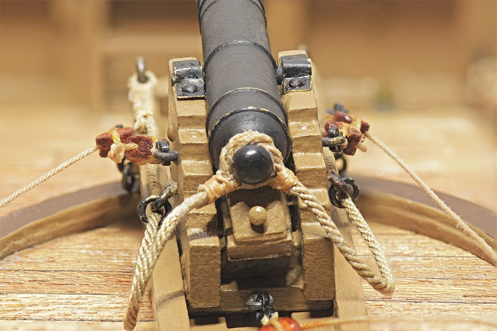
Here is a photo of the finished gun tackle: I decided to use a method for securing the tackle falls like I have seen in photos of some museum ships. After the fall is looped back through the hook eyes it is wrapped around the running parts. This ends up using 20 scale feet of rope! Now only five more to go! I broke another of the tiny 3 mm hooks while trying to hook it over the eye bolt on the gun carriage. The wire is small enough diameter but I was pulling it at an angle. This calls for extra caution when working with these hooks. There will be quite a few more in the rigging. If you look closely at the picture you can see the spacing between the two blocks is about the same as the distance between the front of the gun carriage and the bulkhead frame around the gun port. If the gun was run out I am not sure which would happen first - the carriage would contact the bulkhead or the tackle would be two-blocked. A better arrangement (in hind sight) would be to place the eye bolt on the carriage farther back. Perhaps this is why some guns were rigged with the eye bolts for the gun tackle all the way back at the rear of the carriage, sometimes on top of the carriage sides instead of on the side as shown here. That would allow greater freedom for aiming the gun at an angle horizontally through the port. This build has been a learning experience!
-
Masking tape for curves .
Dr PR replied to LEGION 12's topic in Painting, finishing and weathering products and techniques
Here is a tip I picked up years ago to eliminate bleed through under the tape. Suppose you have already painted one color (say black) and now you want to mask it off and paint another color (say white). If the white bleeds under the tape you will have a ragged edge between the black and white. After applying the tape paint a light thin coat of black along the tape edge. If the paint bleeds it will be black on black, and it will seal any leaks. After the black dries paint over it with the white. If you get a fine bead/ridge of dried paint where the edge of the tape was you can remove it by carefully and GENTLY scraping with a knife blade held perpendicular to the surface (scrape, not cut). Or you can sand the entire surface lightly with fine grit sandpaper and then spray a clear coat over it to get the desired finish (glossy, satin, flat). -
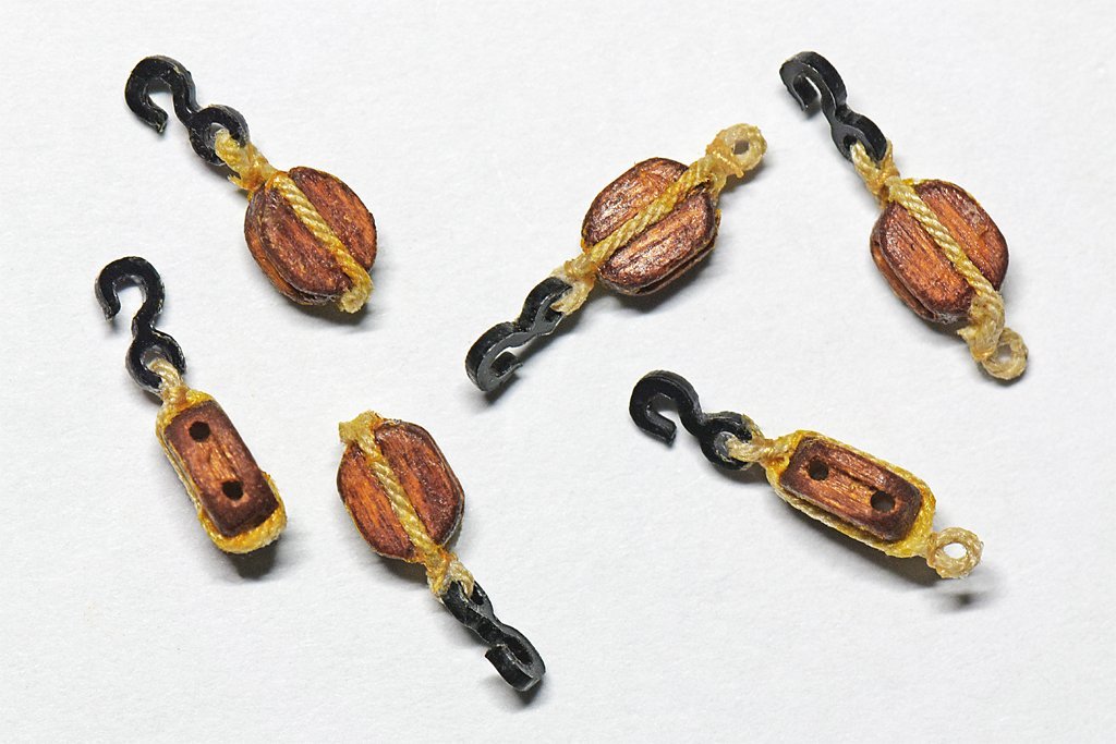
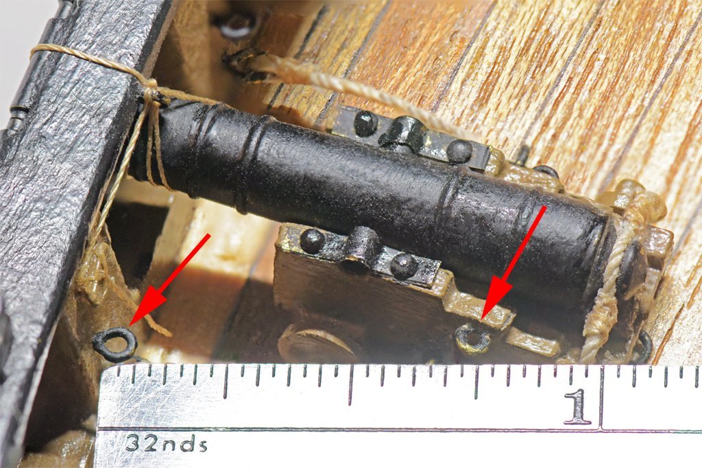
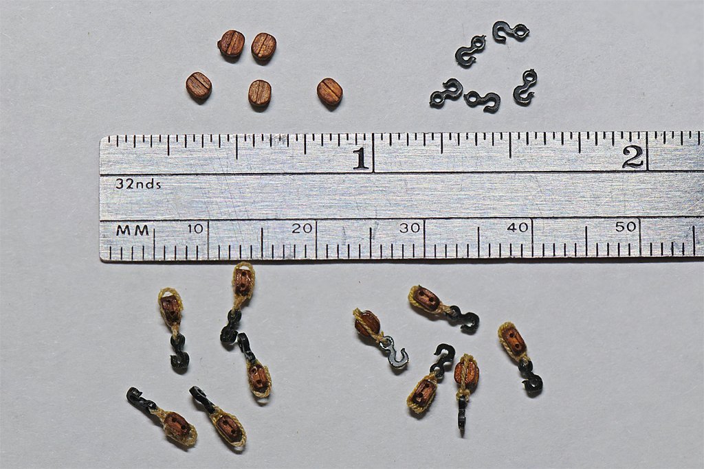
I know I am not alone when I say there are some parts of model building that I enjoy less than others. I have seen some posts saying that hull planking is the least enjoyable task, but I will gladly plank a hull before I have to do cannon rigging! For me it is the most tedious and frustrating modeling task. I have only six small cannons on this model. I think I would go crazy trying to rig a 100 gun ship! Here is the problem: I need to rig the gun tackles between the eye bolt on the bulkhead and the eye bolt on the cannon carriage. As the ruler shows this is a distance of a little less than 3/4 inch (19 mm). I had rigged these tackles earlier, but I did not like the way they turned out. The distance between the points is so small there isn't much room for the smallest of blocks and hooks. When the guns were run out the blocks were almost two-blocked. And the small size makes handling the parts difficult. I have decided to place the guns in the stowed position, and that gives a bit more room. And I have obtained some small (not small enough) hooks to use with the blocks. Here is the plan: I am using Syren 3/32 inch blocks and Syren 3 mm hooks. These parts are very small and hard to handle. Somehow I managed to make 24 block and hook assemblies (4 per cannon) without losing any of the parts! Since these are small 6 pounder cannons I will need a simple gun tackle with two single blocks. Each block and hook assembly will be about 0.2 inch (5 mm) long, leaving about 0.375 inch (9.5 mm) between the blocks. I made two different assemblies, 12 with only the hook attached to the block with an eye in the strop, and 12 with an eye at both ends of the block, one for the hook and one for the standing end of the tackle. The rope is Syren 0.012 inch (0.3 mm) ultra tan, and the seizing is a very fine (about 0.0025 inch/0.06 mm) tan silk thread (the smallest I can find). As you can see below the assemblies came out about as planned. I used shellac to "glue" the seizing in place, and ordinary white "school glue" to fasten the rope to the sides of the block. This white glue dries clear. I did encounter one problem. One of the hook eyes broke as I was straightening the hook and block. Another stretched quite a bit (as you can see in the picture). Maybe the alcohol in the shellac softened the plastic. From now on I will use only the white school glue. Working with the small rope bundles supplied by Syren resulted in tangles almost immediately. I solved this problem by buying some bobbins at a local sewing supply store. There was a variety of types but I chose a metal bobbin with holes that made it easy to secure the loose end. I spent a couple hours carefully winding the rope onto bobbins. Each package of rope from 0.008 inch (0.2 mm) to 0.025 inch (0.63 mm) fit on a single bobbin. The larger diameter ropes (0.035 inch/0.88 mm and 0.055 inch/1.37 mm) were too large to fit on a single bobbin, but these are easier to handle without getting everything knotted up.
-
Airbrush Paint
Dr PR replied to CLovehitch's topic in Painting, finishing and weathering products and techniques
One word of caution about using flat/satin paints. If you plan on adding decals to the model you should use glossy paints. Decals will have a foggy appearance on the "transparent" parts if added over flat/sating paints. The background will be invisible on glossy paints. After adding the decals spray a flat or satin overcoat to seal the decals and get the dull finish. -
Excellent How to Book for masting and rigging
Dr PR replied to Bill Morrison's topic in Masting, rigging and sails
Howard Chapelle's "The Baltimore Clipper" is the best reference for the topsail schooners from the American east coast. It has a lot of information about the construction of these vessels and many hull lines and sail plan drawings. His "The American Fishing Schooners 1825-1935" is the reference for the American fishing schooners, including a 369 page reference section with hundreds of very detailed drawings of just about every part of these ships. -
Ditto. Too many things to do and too little time! The air had been mostly clear in Corvallis - just a bit of smoke a few days ago. We were really lucky after the lighting storms last weekend. Six fires started west of Corvallis, but there was no wind and a tiny bit of rain. Four of the fires were out the next day, and the other two close together were quickly surrounded and put down, limited to 12 acres. And of all things they packed in a sprinkler system - in an old growth forest on a steep mountainside. That was a new one on me!
-
Not just the Western world. When researching my British-Canadian wife's family history (English, Scottish and Irish) we found documents referring to her Japanese father-in-law's (Keijiro Yamada from an earlier marriage) father as Chojiro Sato (yo-shi). We had no idea what "yo-shi" meant. I eventually learned that it meant that the man had taken his wife's maiden name because there were no male descendants in the wife's family. So to preserve the family name the husband assumes the bride's family name. His wife's name was Tsui Yamada. Their children all had the Yamada surname, as do all the descendants, including my step-sons and my grandchildren. So Japan has this "official" procedure for changing the family surname. We learned of this through the Heart Mountain internment camp records from WWII. If you think European genealogy can be tricky, just think what a mess American genealogy can be!
-
I want to repeat what Bob said - many printers do not print to scale. I had a HP laser printer that required a print scale of 1:1.043 to get it to print 1:1 on the paper. 1. Disable "fit to paper" option in the print dialog. 2. Set the scale to 1:1 (every printer manufacturer does this differently - too stupid to come up with a common method). 3. Create an image with a ruler scale in it that is known to be accurate. Best to create this with a CAD program and not a simple drawing program like Photoshop or MS Paint. Make the scale long enough to fit on the paper. For example, 8" horizontal and 10" vertical. 4. Print the test file. 5. Measure the printed ruler. Careful - the error may be small, but these errors can add up. CAUTION: Use an accurate ruler to make the measurement. Many cheap rulers are just the approximate length. Use a steel machinist's rule if you have one, or measure with a caliper. 6. Calculate the error +/-. Divide the measured length of the printed ruler by what it is supposed to be. 7. Calculate the offset +/- necessary to make the print the right scale. For example, if a 10 inch ruler prints to 9.98 inches, set the print scale in the printer dialog to 1.1002 (or 1:1.1002). 8. Repeat steps 3-7 until it comes out right. 9. Write down the necessary scale correction for the printer (put it on a stick on not on the printer). If you can, set the "Custom" scale in the printer dialog. 10. Be sure to test this with a vertical and horizontal ruler in the printed drawing. Some printers are screwed up in both directions, and the only way to correct this is to create drawings that are skewed in both directions!
-
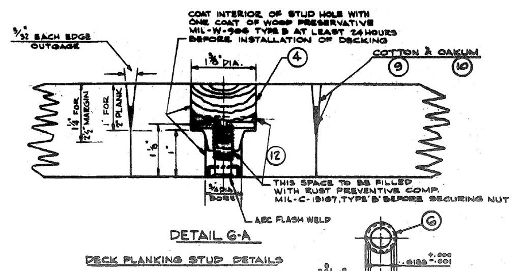
I am not sure if the teak/Douglas fir lamination was used during WWII. The blueprint I took the drawing from was for the late 1950s guided missile conversions. I am sure it was a cost saving measure. In a class at Naval Officer Candidate School an instructor told us that wooden decks served to catch shrapnel splinters and prevent it from ricocheting off the steel decks. However, others have said this wasn't true, and that wooden decks were an insulating feature to prevent heating from the sun in summer and loss of heat from inside in the winter (it does work for this). And others have ventured that they put wooden decks on these ships because ships had always had wooden decks (it gives the sailors something to do by holy stoning them to keep the decks looking nice). Another explanation is that you get better traction on wood than steel, especially when the deck is wet (this is true). I have searched for a documented reason for having wood decks on steel ships and I have found no official explanation. Any other guesses? **** Walking on the studded decks while the decking is being replaced is hazardous - guaranteed stubbed toes! I speak from experience! Also, imagine the challenge of making new planks with holes correctly located to fit over several studs that are already welded to the deck.
-
You can try printing the red/rust on the silkspan, leaving the white silkspan to show the symbols. I haven't tried this. I would go to a local print shop and let the staff there decide if it would work.
-
Bob, Your recollections are she same as on my blueprints for the USS Cleveland CL-55, a WWII era ship. Of course this was a wooden deck overlaid on a steel deck and fastened down with metal studs and nuts. The planks were 2" thick. The plank edges were vertical from the bottom for 1 inch, and then angled (outage) 3/32" at the top to make a 3/16" wide gap. Oops! I thought I remembered a 3/8" wide gap between planks, so my model's deck seams might be 2x scale! I should have double checked the blueprints! The notes on the blueprint say for new planking use planks made of 1" Douglas fir with a 1" teak piece laminated on top. The outage should be 3/32" and vertical for 1/2", then tapering to zero 1 1/8" below the top of the plank. That is a bit different from the drawing. The planking was to be caulked with two strands of oakum, and a third driven in if practicable, to a depth of 1/2 inch. Then the gap was to be payed with "approved black marine glue," allowing the glue to overflow the seams for about 3/16". I wonder how far back in history this practice goes? Old nautical traditions die hard.
-
Jorge, I had the same questions when working on my current model. I have no idea what the width is of the caulking between deck planks on wooden vessels, especially from several centuries ago. But I do have the advantage of serving on three modern (mid 20th century) ships, and I have the original blueprints for two of them that show deck construction. The gap between planks was 3/8 inch (9.5 mm). My model is 1:48, so the grout width would be 0.0078 inch (0.2 mm). This is about the thickness of some black construction paper (0.008 inch) that I had, so that is what I used. However, before settling on this method I did a series of experiments using six different techniques that I describe in this link: https://modelshipworld.com/topic/19611-albatros-by-dr-pr-mantua-scale-148-revenue-cutter-kitbash-about-1815/?do=findComment&comment=602855 After choosing the black construction paper I added this "grout" as described here: https://modelshipworld.com/topic/19611-albatros-by-dr-pr-mantua-scale-148-revenue-cutter-kitbash-about-1815/?do=findComment&comment=603771 https://modelshipworld.com/topic/19611-albatros-by-dr-pr-mantua-scale-148-revenue-cutter-kitbash-about-1815/?do=findComment&comment=605072 Planking and nibbing turned out to be very easy, and the paper gave a very consistent widths with none of the mess from liquid pigments soaking into the wood grain. I made the paper width a bit greater than the plank thickness so the paper stood a bit "proud" above the planks. I then scraped the deck with a razor blade perpendicular to the wood surface (so as not to cut into the wood) and at an angle across the plank edges to scrape away the excess paper, and then sanded to get a smooth deck. Afterward I coated the deck with a clear sealer and rubbed down with #0000 steel wool. The results look very nice to my eye, and I think the effect is to scale. You can judge this for yourself. **** At 1:72 scale a 3/8 inch grout will be 0.0055 inch (0.13 mm) and you can probably find black paper this thick or a bit thinner.
-
The Joyner LIbrary at East Carolina University has the full collection of plans from the Barbour Boat Works. They made just about every type of small boat used by the Navy during and after WWII, including several types of landing craft, and some not so small (destroyers). https://librarycatalog.ecu.edu/catalog/918210 http://digital.lib.ecu.edu/special/ead/findingaids/0758/ Box 42 has the plans for the LCVP. You can order them online. I have several digitized plans I got from the Joyner Library and they are excellent copies of the original blueprints.
-
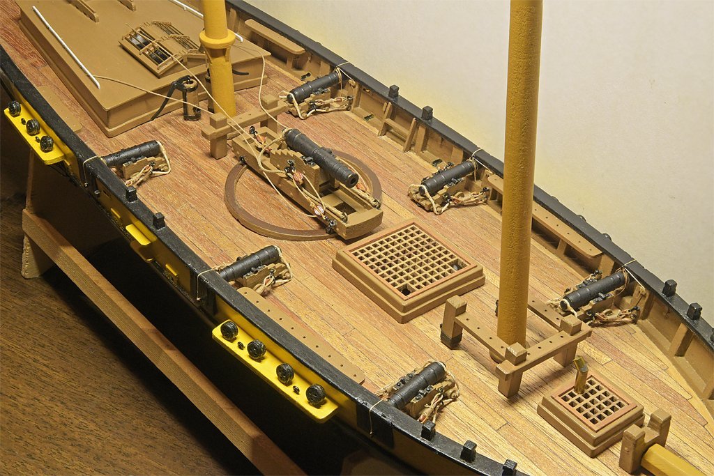
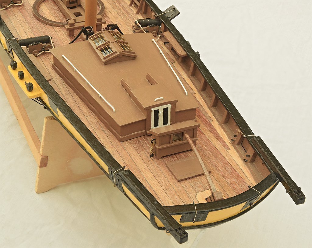
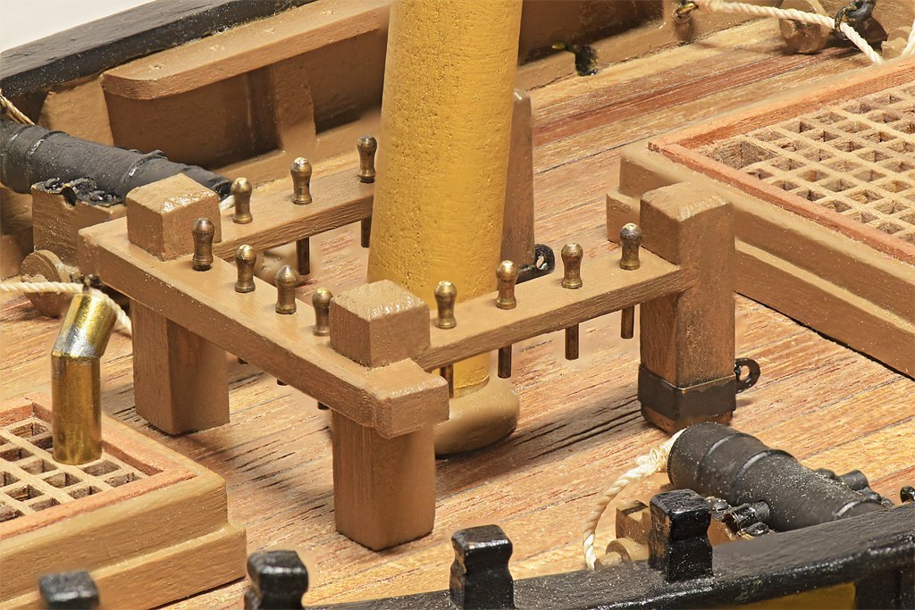
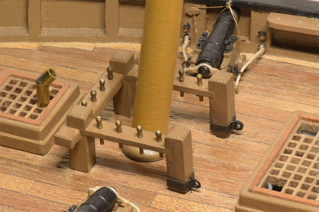
The fife rail at the base of the fore mast was my next project. With my original belaying plan I had eleven tackles attached to ring bolts around the base of the mast and twelve lines belaying to pins on the fife rail. This was much too crowded around the mast base. All of these lines should be belayed at the base of the mast and not on ring bolts or pin rails on the bulwarks (or cleats on the shrouds). After studying several references I realized that not all of the tackles need be at the base of the mast. In particular, the fore course yard lifts and the topsail yard lifts could be rigged with the tackle between the yard arms and the mast, with the falls coming down to belay on the fife rail. This eliminated four tackles at the base of the mast. The remaining seven tackles can be arrayed around the mast without crowding. With that problem solved I could make the fife rail. The main stays (port and starboard) will belay to the metal eyes at the base of the after posts.
-
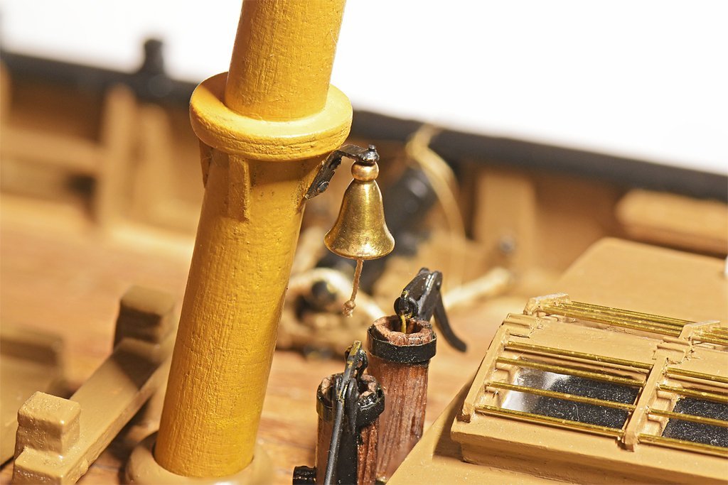
Well, I decided that fancy belfry was too highfalutin' for this simple vessel so I put the bell on the main mast as I originally planned. But I didn't use a separate band around the mast below the boom rest supports because that would place the bell too low and interfere with the pumps. I did want it a bit below the top of the boom rest so it didn't interfere with the bands and other fittings on the boom jaws.
-
It was common to drill a hole through the stem and lead the bobstay through the hole. Sometimes the bobstay was run doubled, just looping through the hole in the stem with some small stuff seizing near the stem. The other ends were spliced around a deadeye, heart or thimble with lanyards to pull them taut. In the mid to late 1800s chain replaced rope for the bobstay, and metal brackets were fastened to the stem for the chain to attach to with a shackle.
- 177 replies
-
- 2
-
-
- Perseverance
- Modellers Shipyard
- (and 1 more)


