


Dr PR
-
Posts
2,471 -
Joined
-
Last visited
Content Type
Profiles
Forums
Gallery
Events
Everything posted by Dr PR
-
 It was common to drill a hole through the stem and lead the bobstay through the hole. Sometimes the bobstay was run doubled, just looping through the hole in the stem with some small stuff seizing near the stem. The other ends were spliced around a deadeye, heart or thimble with lanyards to pull them taut. In the mid to late 1800s chain replaced rope for the bobstay, and metal brackets were fastened to the stem for the chain to attach to with a shackle.
- 177 replies
-
- 2
-

-
- Perseverance
- Modellers Shipyard
- (and 1 more)
-
John, Thanks for the information and photos. A cruise on the Bluenose II! That is really nice! I like the position of the bell on the fore mast. I do have room there to place the bell although it is in a lot of lines leading down to belay on the fife rail. I also need to put a band around the fore mast to hold up the mast hoops and keep them from dropping down on the fife rail when the sail is not attached. Maybe I can accomplish both goals with a single fitting. I think I will give more thought to putting the bell on the main mast like your Bowdoin. It doesn't have the rigging complications. I would use a cross between the Bluenose and Bowdoin - a separate metal band around the mast below the boom rest.
-
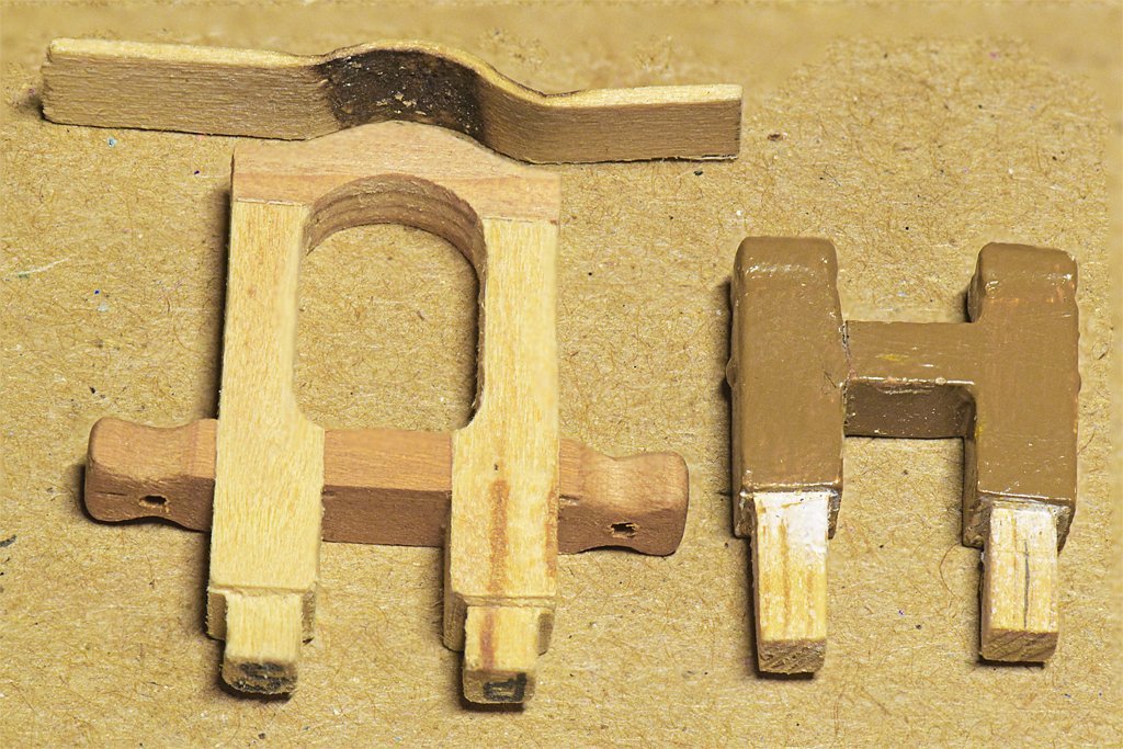
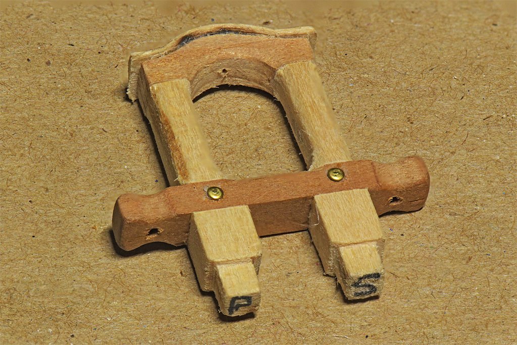
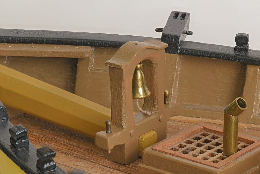
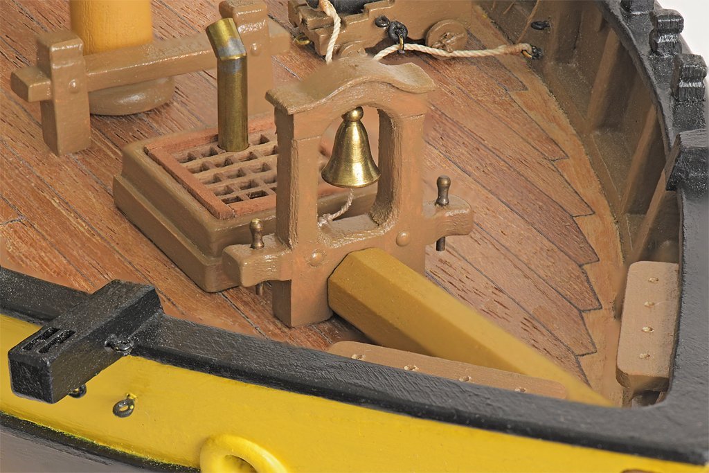
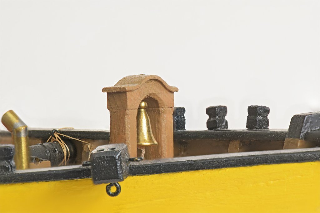
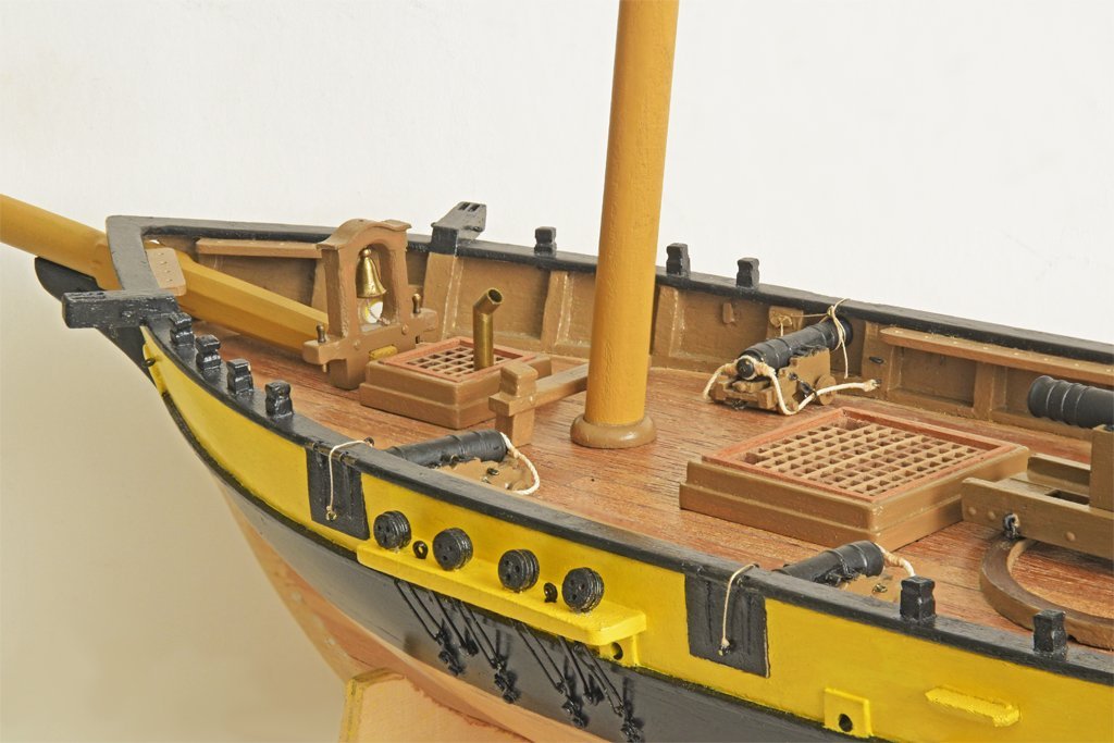
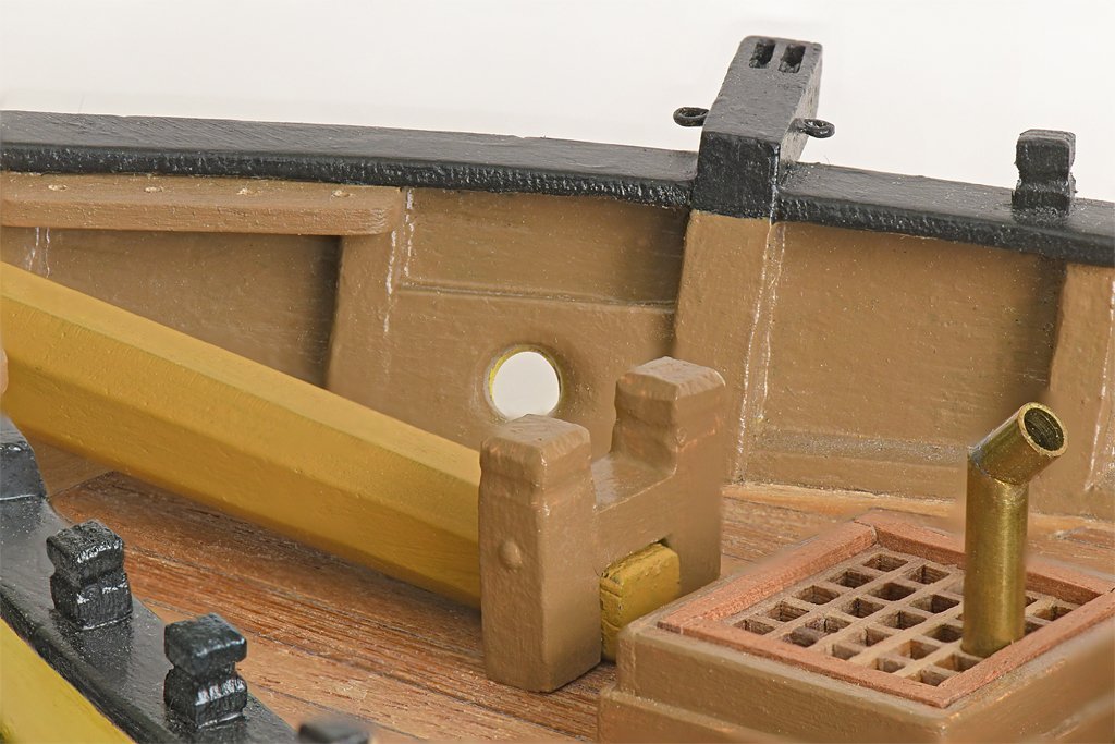
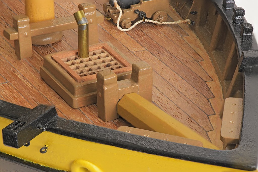
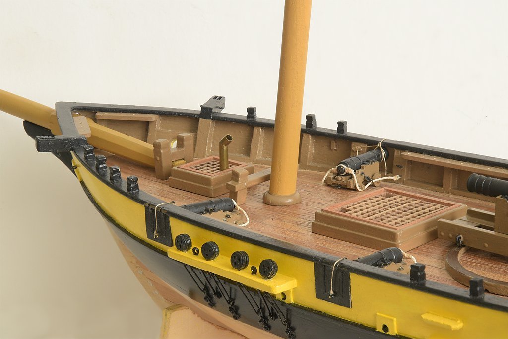
I looked for examples of the ship's bell hanging from a sailing ship mast and found none. I did find some examples on 20th century ships. In fact, there seems to be very little written about the bell. But Wolfram zu Mondfeld (Historic Ship Models, Sterling Publishing, Inc., New York, 1989, page 158) does describe ships' bells and variations over the centuries. He says the bell was originally located somewhere near the stern, usually in an ornate belfry, until the 18th century when the bell moved to the bow. But, of course, he talks about ship bells, and not schooners. I looked at photos of schooner models and recent real vessels, and even there it is difficult to find photos of the bells. But I did find a few, and since schooners are a relatively new type of ship, all have the bell near the bow. I looked for a place to place a simple mount somewhere on deck on my model, and there really isn't free deck space where the bell could be mounted and not interfere with something else. But I do have bitts that form the bowsprit step. I wondered if I could extend those bitt timbers to form a belfry? I decided to experiment with a fancy belfry to see what it looks like. The original bitts and bowsprit step are shown on the right. I made a belfry that had the same dimension timbers and spacing for the bowsprit step with the bitts extended to support a cap to hold the bell. The cross piece of the step was extended to provide purchases. Over the top of the belfry is a thin strip of wood that was soaked in water and then bent using a soldering iron to heat the wood. Here is the assembled belfry before painting. The "bolts" are 8 mm brass nails. The cross piece ends are drilled to carry belaying pins. The belfry is quite a bit taller than the original bitts. The cross piece is about a foot above the deck and the entire belfry is just four feet tall. Although this isn't very high it is much taller than the other deck furniture. The galley stack, deck house and binnacle are only about three feet tall, and the bulwarks and cap rail are about three feet high. Is it just too tall for this vessel? A series of pictures follows showing the original bitts and the new belfry for comparison. Well, it does appear to stick up pretty high, but maybe not too high. The foot of the fore staysail is about 4 1/2 feet above the deck in my current plans so maybe I should raise it a bit for more clearance.. I can see no reason this belfry won't work, and it does provide a home for the bell at the bow. It is probably a bit too fancy for this mundane revenue cutter. I'll have to think about it and see if I can figure out a simpler and less obtrusive belfry.
-
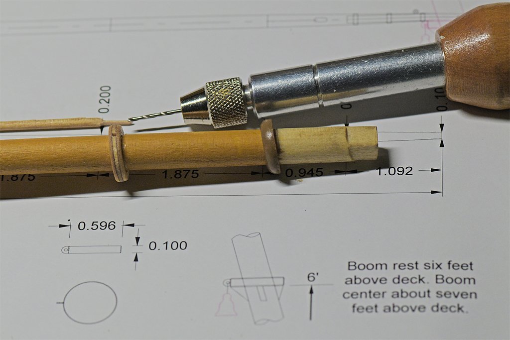
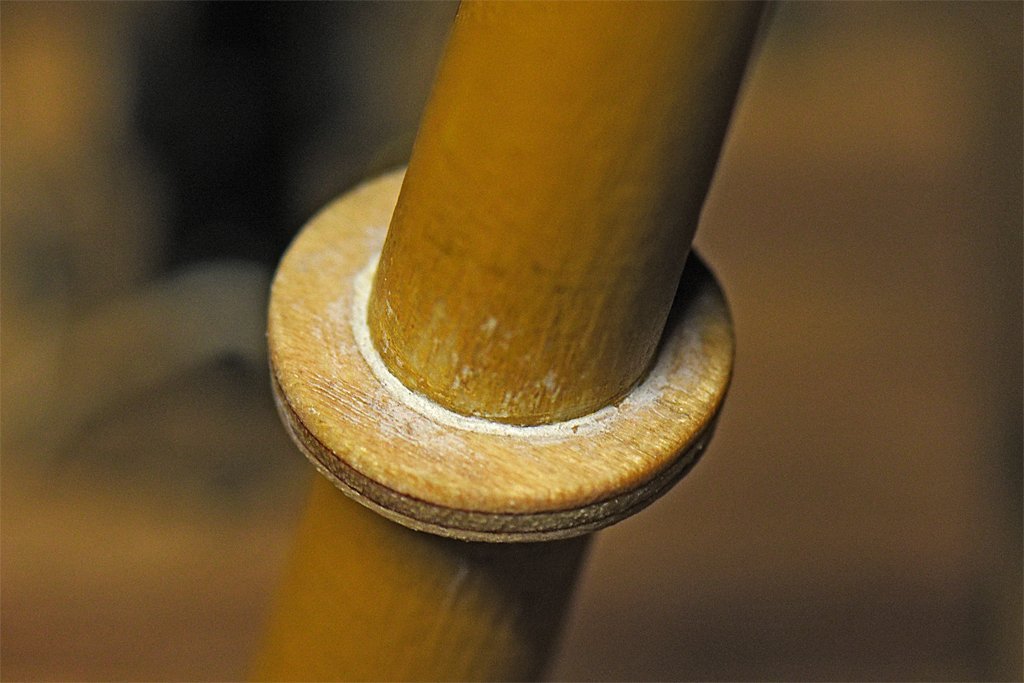
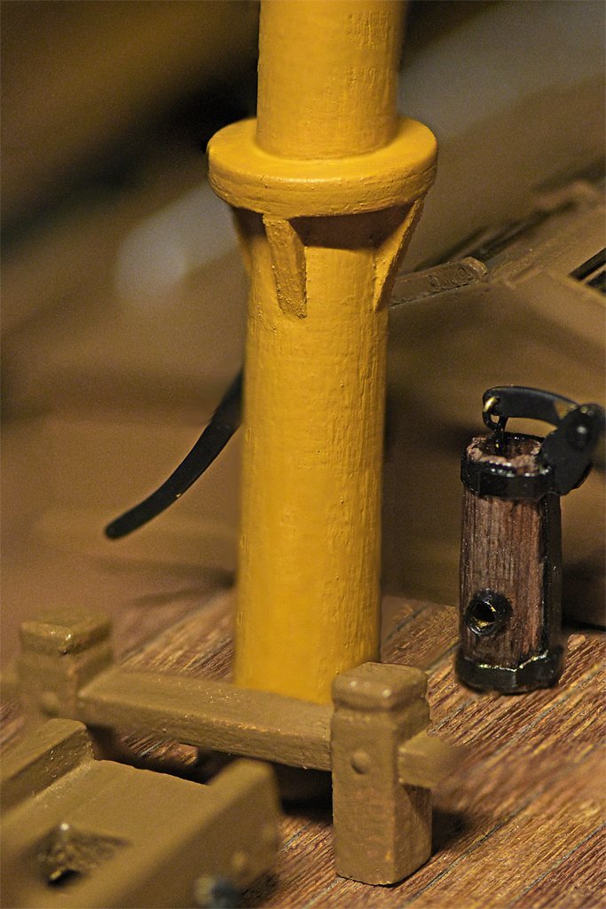
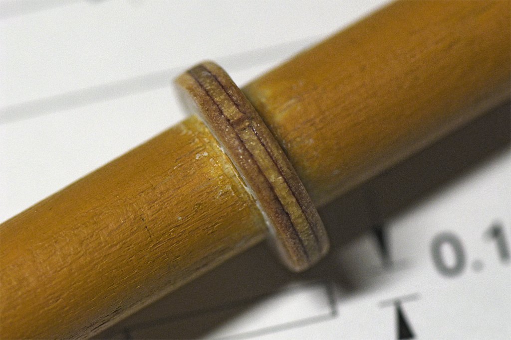
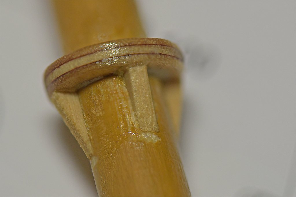
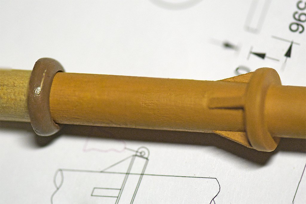
I have been working on the boom rest for the main boom on the main mast. It is a pretty simple piece, but I had to do a bit of research before making it. The first question was whether it should circle all the way around the mast or should it be "C" shaped with the gap on the front side of the mast? I have seen both, but the "C" shaped parts were on square riggers where the driver/spanker boom does not seem to swing wide over the side. On schooners the gaff sails are often swung far out over the side to catch following winds, so I made the boom rest circular to accommodate this. How high above the deck it should be placed? Obviously it should be high enough to clear the deck furniture when the boom swings, but that is only a few feet. It seemed to me that the boom should swing high enough to pass over the head of the helmsman. I looked at several drawings in Chapelle's books that showed the deck and the boom above it, and had a scale in the drawing. From this I learned that the boom height ranged from 5 feet to 9 feet (1.5 to 2.75 meters) above the deck (lower on smaller vessels and higher on larger ships), but 6 to 8 feet (1.8 to 2.4 meters) was more common. So I decided to place the bottom of the boom rest 6 feet above the deck. The rest is a scale 6 inches (152 mm) thick, so the boom centerline will be about 7 feet (2.1 meters) above deck. Drawings and photos I have of replica vessels show from 4 to 8 supports under the boom rest, arranged symmetrically around the mast. Since this model is of a fairly small vessel I decided to use four supports. I cut the circular rest from a sheet of 1/8 inch model airplane plywood. I used plywood because I thought a piece cut from a plain sheet of wood would be fragile and probably break along the grain as I was shaping it. The plywood was three layers with grain arranged at right angles. I made the piece with no problems. In addition to glue to hold the rest in place I made a 0.040" (1 mm) dowel from a bamboo skewer. This was inserted into a glue-filled hole through the boom rest and into the mast. The wooden pin was sanded smooth with the edge of the rest and then any gaps were filled with white modeling putty. After that I cut four triangular supports from a 1/16" piece of basswood and glued them below the boom rest. When the glue dried I coated the new pieces with shellac. After that dried I painted the whole thing with the straw color paint used on the masts. Now I need a boom to place on the boom rest! Oh, I did remember to put the mast hoops on the mast before I installed the boom rest! I have been trying to decide where to mount the ship's bell. There is no space on deck for a fancy belfry, and these vessels were fairly inexpensive to build and didn't have a lot of decoration. I think I will hang the bell from the boom rest on the aft side of the mast (some lines run down the forward side to purchases on deck). I have seen several examples where the ship's bell was mounted on a mast.
-
Someone used to sell an emulsion of radium for upset stomachs. We had an empty bottle in the department "museum" when I was an undergraduate. Unfortunately, it caused stomach cancer and certain death. But I guess that did put an end to upset stomachs!
-
There is another way to make curved top rails that I saw on one of the build logs on the forum. Rather than try to cut complex curves from a sheet of wood, especially sharp curves at the transom, the fellow built the top/cap rails up from many thin wood strips that were wrapped around a solid mold. The rail was built up with many laminations glued together. The wide dimension of the strips was vertical to the plane of the rail so they were bent easily around the curves through the thin dimension of the strips. The thin strips were a bit wider than the thickness of the rail so the finished piece could be sanded to proper thickness. Additional strips were glued on until the laminated piece was the desired width of the cap rail. After sanding to thickness and sealing with shellac the laminated rail looked quite elegant. After painting you couldn't tell the rail wasn't carved from solid wood. I think he made the thin strips with a plane, cutting shavings from the edge of a thin board/plank a bit thicker than the desired top/cap rail thickness. The blade of the plane was set to create relatively thick shavings. For thin curved wood parts this method produces a piece that is much stronger that a carved part, and has no grain the piece can break along. I have used the same technique to make wooden mast hoops only 0.020 inch (0.5 mm) thick that are very strong..
-
rich, I don't have much experience with the Birchwood Casey Brass Black but it is easy to use and works well on brass and tin-lead solder. https://modelshipworld.com/topic/19900-brass-black/?do=findComment&comment=991402 However, if you will be blackening parts with relatively large surfaces (and not just wire) I suggest you read through the thread about blackening brass on the forum. It is very important to get the metal surfaces clean to get even blackening without spots or streaks. Many people recommend etching the brass surface (there are several methods) before blackening, so the process can involve several steps.
-
Pin Vise vs. Hand Vise?
Dr PR replied to Balclutha75's topic in Modeling tools and Workshop Equipment
I have the swivel head pin vise shown above and use it a lot. But it has several issues: 1. It will not hold the very small drill buts - nothing smaller than about 0.025 inch (0.6 mm). 2. If I am using several drill bits it is a nuisance to have to be switching collets back and forth. 3. It does not allow the use of long drill bits (no opening in the swivel part). This is a problem only if you are drilling very deep holes and I have done that only a few times in the last four decades. 4. Similarly, it cannot be used to hold long rods with just the end protruding from the collet. I modified my other pin vise (with a fixed wooden knob) to allow long rods and drill bits to be used. Not long ago I purchased the four piece set also mentioned above. These have turned out to be invaluable! I may use them more than the first pin vise. The smallest size will hold the tiniest drill bits (#80, 0.0135 inch/0.34 mm) firmly. They do allow the use of long bits or rods, and they can be chucked into a milling machine, drill press or lathe (however, I doubt they are made with enough precision to use with the smallest bits in a milling machine). Having said this, hand drilling with the very small bits is just asking for a broken bit! Chuck the bit all the way into the pin vise with just enough extending necessary to drill the depth needed! -
Howard Chapelle's "The American Fishing Schooners 1825-1935" (W. W. Norton & Company, New York, 1973, 690 pages) is an excellent reference for these fishing schooners. The 370 page "Notebook" at the back of the book has detailed drawings and descriptions of many details on these vessels.
-
Lettering
Dr PR replied to bobc622's topic in Painting, finishing and weathering products and techniques
I have used rub-on dry transfer letters as stencils for painting. I developed this technique when I couldn't find the correct colors for the lettering on a railroad engine model. 1. First I paint the surface the desired letter color. 2. When that is dry I rub on the letters. 3. Then I spray over the letters with the desired surround color. 4. After the paint is dry I lift off the rub-ons with masking tape. **** The advantages of this technique are: The rub-on letters are relatively thick and stand out on the model surface. The resulting painted letters are just a layer of paint thick. Rub-on letters can peel off when they age. Paint doesn't (shouldn't if painted correctly). You can have any color letters (paint) you want - the colors of rub-on letters are limited. Any color dry transfer letters will work. The paint flows into cracks and uneven surfaces better that dry transfer letters (or water slide decals). You do not have to cover the painted letters with a clear paint coat to prevent them from aging and turning yellow. **** Look in craft stores. I have seen large selections of fonts and sizes. -
Wefalck's "chain" looks pretty good. I think the black coated wire he used adds to the impression. Also I suspect there is just the "right" twist to get appropriately sized "chain links." I have wondered how I would make very small chains for lifelines at 1:96 and if I ever get around to working on my cruiser model I will try this.
-
We used to make multi-stage rockets with ordinary fireworks rockets (before Estes and hobby model rockets were a business). Two stage rockets were easy. The largest we made was a four stage monster. The first stage was four of the largest rockets wee could buy. They were wrapped with masking tape and the fuses twisted together. The second stage was three slightly smaller rockets taped together. Again the fuses were twisted and then inserted into a hole we drilled in the clay plug at the end of one of the first stage rockets. The third stage was one of the smaller rockets with the fuse in a hole in the top of one of the second stage rockets. The fourth stage was a tiny bottle rocket sized thing with a plastic nose cone and metal fins. It whistled loudly when it burned. The whole thing was about 1 1/2 feet (0.5 meter) tall. We used a spark gap in the leads from a neon sign transformer to light the fuses. The transformer was plugged into a long extension cord that was plugged into a switchable wall outlet. Just flip the switch - ZAP - and away they went. We launched a bunch of two stage rockets this way. That is how it was supposed to work. But gak1965 named the problem with the four stage monster. One of the four first stage rockets ignited before the other three. Unlike all the other rockets we fired that left the launch pad in a hurry, the four stage rocket rose slowly - just like the Saturn 5. As it rose it tipped over and was about horizontal when the other three rockets fired. Whoosh! Crash! It hit the side of a neighbor's house and fell into a rose bush where it thrashed around until the motors burned out. The neighbor kid was watching at the fence between the yards and the rocket just missed him. The rose bush was toast! **** We did recover the second, third and fourth stages. After some reassembly we launched them successfully as a three stage rocket.
- 227 replies
-
- 10
-
-

-
Look at Wefalck's S.M.S. Wespe build. He used very thin wire twisted together to simulate small chain. https://modelshipworld.com/topic/8957-sms-wespe-armoured-gunboat-1876-of-the-imperial-german-navy-by-wefalck-–-1160-scale-when-first-commissioned/?do=findComment&comment=977727
-
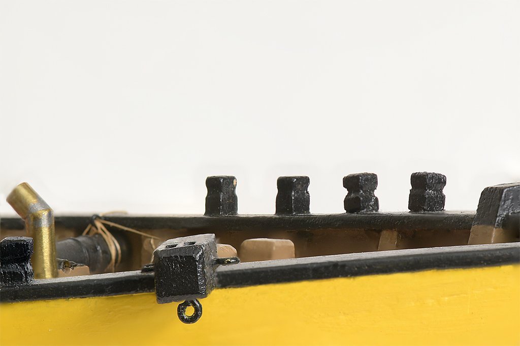
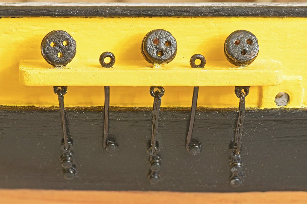
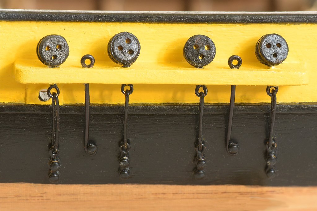
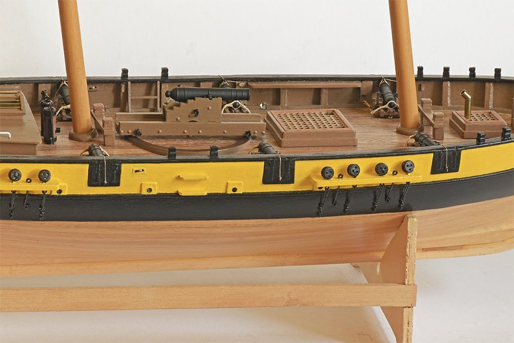
More fiddly bits. The fore course sheets led back to midships. The fixed end was attached to a ring bolt outboard. The running part passed through a single block attached to the sail's clew and back to a sheave in the bulwarks. Inboard the fall was secured to a cleat on the bulkhead. I made the blocks for the bulkhead sheaves from a 0.125" x 0.125: x 0.25 inch (3.2 mm x 3.2 mm x 6.4 mm) piece of scrap wood. The long slots were cut out with a 0.039" (1 mm) drill and finished with a small file. The slots were 0.15" (12 mm) long. The 0.125" (3.2 mm) diameter sheaves were made by soldering 1/16" (1.6 mm) and 1/8" (3.2 mm) concentric tubing together and cutting off thin slices. These were filed/sanded down to 0.035" (0.9 mm) thick. A toothpick was trimmed to a 1/16" (1.6 mm) dowel that served as the pin for the sheave. The inboard and outboard edges were beveled to leave a surface about 1/16" (1.6 mm) wide, the thickness of the hull planking. The sheaves were fitted into holes cut through the bulwarks a bit below the cap rail. A cleat was fastened to a frame just forward of the sheave position. It was a lot of work for just two small details. If I do add sails to the model I probably won't install the fore course, so these sheaves and cleats won't be used. But they do add another small bit of detail to the model. I also added "chains" in the channels for the fore and main mast tackle. Originally I just had one eyebolt through the channel, but this didn't provide a place to secure the fall, and it wouldn't have been strong enough to take much pull from the tackle (there shouldn't be much load because this is just stowage for the ends of the tackle). I originally made the port side gunport lids closed with the cannons stowed, and the starboard port lids open with the cannons run out. However, the open lids were often bumped, the hinge straps were bent, and the port tackle lines broken. It was a continuing nuisance so I decided to close the starboard side lids. I will need quite a few eyebolts and ringbolts for attaching rigging to the hull and deck so I started making these. I have posted my method for making the eyebolts and blackening them here: https://modelshipworld.com/topic/19900-brass-black/?do=findComment&comment=991402
-
I have just used a common modeling knife and lightly scraped with the blade perpendicular to the surface. Just go slow and be careful to nhit only the high spots along the edge of the paint.
-
Gun Port Hatches
Dr PR replied to acaron41120's topic in Building, Framing, Planking and plating a ships hull and deck
Wolfran zu Mondfeld's "Historic Ship Models" (Sterling Publishing Co. Inc, New York, 1989) shows a variety of gunport lids on page 177. He discusses the variations on lid design and hinges from the 16th century through the 19th century. -
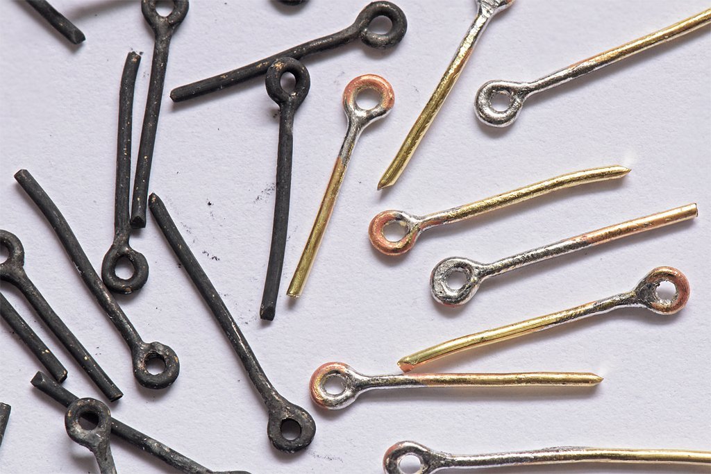
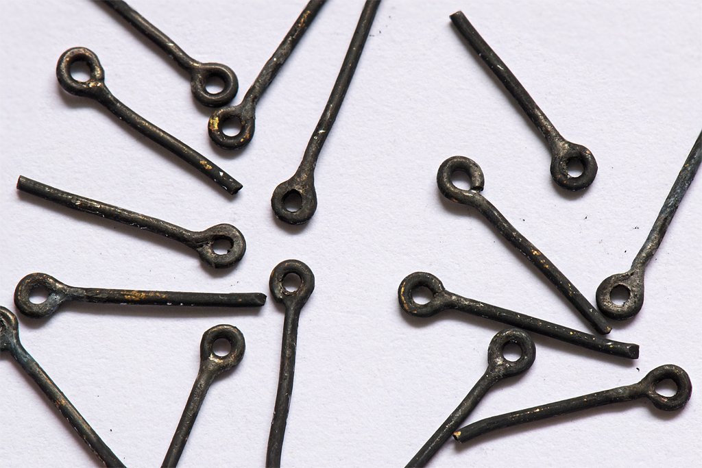
I have asked several times if blackening compounds will blacken solder - with no answers. So I decided to experiment to see how well it works. I have been soldering since I was a kid, and I like working with brass. On my current build I will need a lot of eye bolts and ring bolts. I can bend the brass wires into shape, and they will hold against light forces, but thin threads can slip through the gap. I prefer to solder the gap in the ring, as much for aesthetic purposes as to increase the strength. Up to now I have been painting the brass fittings with flat black enamel, but this is easily chipped when handling the parts. And the paint does add significant thickness to small parts. So I wanted to try blackening the metal to see if that gave a more durable finish. Here is a photo of some eye bolts with soldered gaps. The wire is soft brass, 0.025" (0.635 mm) diameter, and the hole is 0.035" (0.889 mm) diameter. This is a good size to work with Syren's new 4 mm plastic hooks. I used a liquid water soluble flux, and the solder was tin/lead 60:40 with a resin core flux. After soldering there was some flux residue. First I washed in water to remove the water soluble flux. Then I washed in acetone to remove the resin flux and grease. It only takes 10-20 seconds for the flux to dissolve completely. Next I placed the parts in Birchwood Casey Brass Black diluted 50:50 with water. I let it stand 10 minutes, at 67F (19C) stirring occasionally, and then washed with several water rinses. You can see from the photo that the solder blackened just as much as did the brass wire. Hooray! This was very important to me because there is a lot of solder smear over the wire and I don't want this shiny silvery surface to show. But is the blackening just a thin film on the solder, or is it actually blackened metal? The photo shows some pieces straight out of the blackening solution (after drying) on one side and some that have been rubbed with soft cotton on the other side. Which is which? Those on the left have been polished, and the parts on the right have not. A small amount of the black did rub off of all the pieces onto the cloth as others have reported. However, the blackening didn't rub off the solder any more than from the brass! For small parts like these eye bolts the process I used is adequate. But you can see some bare spots, perhaps from flaking. The pieces turned dark almost immediately after I placed them in the blackening solution. However, it seemed the solder took longer to darken than the brass. Perhaps five minutes in the solution would be enough? For larger surfaces it might be a good idea to etch the brass with Sparex before blackening to get a more uniform finish and avoid flaking.

-
I lived on the top of a hill, and we (the other 14 kids in the neighborhood and I) rolled or slid everything we could come up with down that hill. We made our own "go carts" out of scrap wood and whatever wheels we could find. One just used the wheels and axles from a wagon. The wheel base was very narrow and it had a tenancy to flip and roll, so it had a seat belt, high seat back and crash bar. The front axle was on a board that pivoted on a bolt for steering. We rigged a steering wheel that worked like the steering drum on a ship's wheel. However we initially rigged it backwards so when we turned the wheel to the right the cart turned to the left. Most of us got used to it, but there were a couple of kids that never learned to steer. So I re-rigged it to work right. It had "brake" that was a board that hinged on a large nail. The top end was the handle and the bottom dragged on the pavement. Pull up on the handle to jam the other end into the road surface. It worked to hold the cart in place on the hill, but there was no way it would stop or slow down much if the cart was rolling. A later version used four foot long 2x6s for the axles, with the wheels at the end. The front axle hinged on a bolt for steering, and we just pulled on a rope that connected to the ends of the steering axle. This was much stabler and would not flip or roll, no matter how hard we tried - and we did. However, one time when I tried to do a 180 spin at speed the front axle swung all the way until a wheel jammed into the long 2x8 that was the cart frame. That put the two front wheels more or less in line with the cart body, giving only a triangular footprint on the road, and really putting on the brakes! The cart stopped suddenly and tried to flip, launching me over the front. Fortunately I was wearing a high school football helmet that belonged to one of the kid's older brother. Unfortunately, the helmet broke when I hit the pavement, but I came out of it without a scratch on my head. Then we had to explain how I managed to break the helmet! **** When we got a good snow we raced our sleds down the hill in the street. We also sledded down the hill in the lawns, slaloming between tree trunks. The driveways to the houses made natural "ski jumps" and we built up snow ramps to make them even higher. Half the time we parted company with the sleds in the air.
-
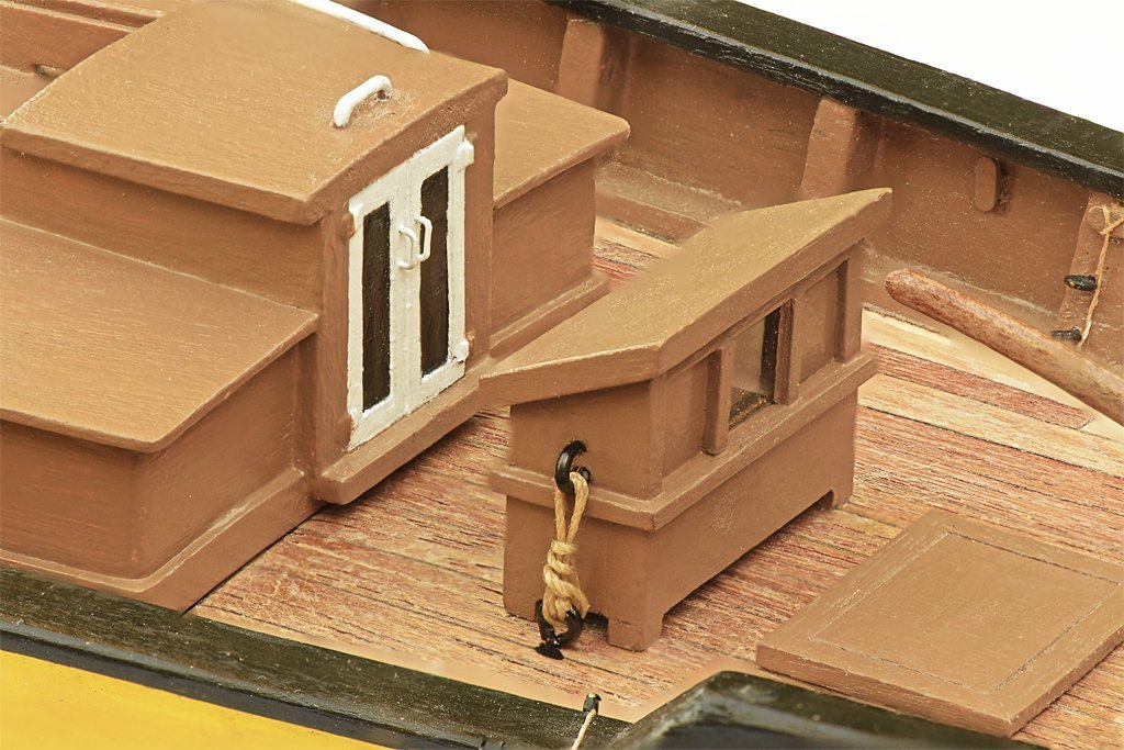
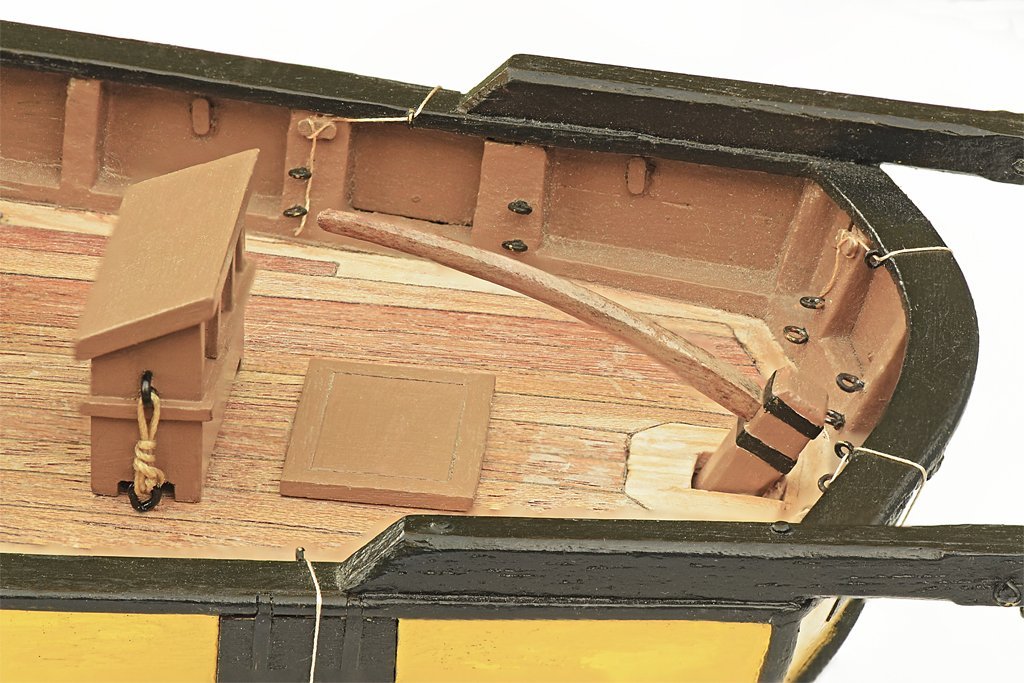
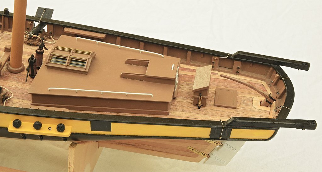
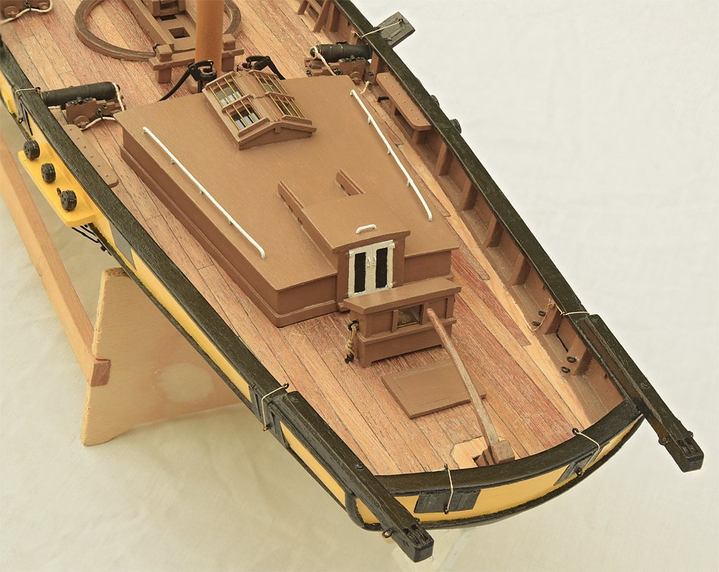
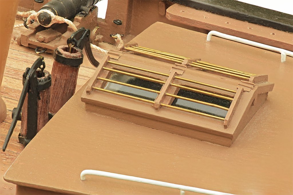
I am working on details on deck that need to be finished before I can start the rigging. The binnacle was finished several years back. I have fastened it to the deck with lashings to eye bolts. The binnacle was "portable" furniture. Portable means not permanently built into the ship's structure. I also added handles for the doors in the companionway. The lazarette hatch is in place. A lazarette is a storage space in the stern of a ship. I have seen a reference that said the space was used to store bread. I added hinges for the skylight openings. I suppose this is getting down to knit-picking, but ever since I built this skylight I have thought I should put some hinges on it.
-
I used Fiebing light brown leather dye to stain some castello boxwood blocks. The parts were dipped into the dye for about a second and then rubbed with cloth to remove excess dye. The sides of the smaller blocks are a nice light reddish brown, but the end grain is almost black! On the larger blocks the sides came out a mottled light and dark brown. I used a paint brush and ethanol to redistribute the stain, but they still look pretty awful! Where the blocks were too dark I dipped them in alcohol until the stain started to bleed and they came out much lighter.
-
Tiller tackle
Dr PR replied to Dr PR's topic in Discussion for a Ship's Deck Furniture, Guns, boats and other Fittings
Wefalck, Unfortunately I live in an area with very few nautical resources. I really can't afford (or don't want to) the exorbitant costs to travel across North America or to Europe to research these things. So I am limited to what I can find on the Internet and local libraries. That is why this and other ship modeling forums are so important. You and I are having this conversation from opposite sides of the planet! You are sharing your knowledge with me, and all the others around the world, on this forum. Thank you and the others who participate in these discussions! -
Tiller tackle
Dr PR replied to Dr PR's topic in Discussion for a Ship's Deck Furniture, Guns, boats and other Fittings
Wolfram zu Mondfeld (Historic Ship Models, Sterling Publishing Co, Inc, New York, 1989, page 148) says the ship's steering wheel was introduced early in the 18th century, superseding the whipstaff. Bjorn Landstrom (Sailing Ships, Doubleday & Company, Garden City, New York, 1969, page 161) says the same thing. George Campbell (The Neophyte Shipmodeler's Jackstay, Model Shipways Co. Inc., Bogota NJ, 1977, page 26) also says the wheel came into use in the early 18th century. None of these authors gives a reference. -
Tiller tackle
Dr PR replied to Dr PR's topic in Discussion for a Ship's Deck Furniture, Guns, boats and other Fittings
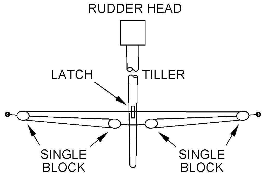
Wefalck, The tackle shown on the Levante model is similar to what I saw on the Lady Washington and some other ship models. It appears to be the "steering tackle" that Marquadt describes. However, it isn't the same as on the Lady Washington - the left (first) drawing is the Lady Washington rig, and the right drawing (second) is the steering tackle that Marquardt describes and appears to be on the Levante model. Now I guess my original question, when the Lady Washington rig came into use and how common it was, has become a question about both of these rigs. The Levante model indicates the steering tackle was in use in the 1830s. The mechanical advantage it provides for controlling the rudder is obvious. And it is easy to see how it was adapted to work with a steering wheel turning a drum with the rope wound around it. It is also easy to see how the steering tackle was modified to get the Lady Washington rig. But it seems to me that the Lady Washington rig gives the same mechanical advantage as the steering tackle rig Marquardt describes, plus it provides a simple way to secure the rudder at a desired angle. It isn't much different from the steering wheel mechanism. This is just another rabbit hole to fall into when trying to understand running rigging on ships of the past!
-
Tiller tackle
Dr PR replied to Dr PR's topic in Discussion for a Ship's Deck Furniture, Guns, boats and other Fittings
I have been looking through Marquardt's "The Global Schooner" and have found a few model photos and illustrations showing what appears to be this rig. Actually, on some earlier and smaller vessels the rig may have used only two single blocks attached to opposite sided of the deck by the bulwarks. The rope ran from the tiller through one block, through the other, and back to the tiller. On page 152 Marquardt describes "steering tackle." Two tackles were rigged on either side of the tiller. The rope was attached to the side of the deck. From there it led through a sheave in the tiller and back to a block attached to the side of the deck. From this block the rope ran forward where it was handled. The vessel was steered by hauling on the tackle on one side and letting out the line on the other. This is different from what I have described above. It was a simple modification to use a single rope that passed through both blocks and around a drum that was turned by a steering wheel. -
Tiller tackle
Dr PR replied to Dr PR's topic in Discussion for a Ship's Deck Furniture, Guns, boats and other Fittings
Allan, Thanks. One of the problems (the major problem?) with trying to build a model of historic vessels is determining the small details, such as this rudder control rig. I can find descriptions of the whipstaff-tiller arrangement, and the more elaborate rigging from a ship's wheel to the tiller. But if a vessel had just a tiller attached to the rudder, that is all there is to it.

